Article

Study on Reinforcement Measures for Wood Composite Beams with Discontinuous Cross-Section in Web Opening

College of Civil Engineering, Southwest Forestry University, Kunming 650024, China
*
Author to whom correspondence should be addressed.
Forests 2024, 15(8), 1318; https://doi.org/10.3390/f15081318 (registering DOI)
Submission received: 14 June 2024 / Revised: 18 July 2024 / Accepted: 25 July 2024 / Published: 28 July 2024
(This article belongs to the Special Issue Wood: Types, Properties, and Utilization)

Abstract

:
On the basis of existing experimental studies on web-opening wood composite beams, six new types of reinforcement were proposed in this study. The effects of different reinforcement measures on mechanical properties such as the load-carrying capacity, deformation capacity, internal force distribution law, and force transfer mechanism of web-opening wood composite beams were investigated. The results show that the stress distribution in the opening area is more uniform after reinforcement, and the influence of different reinforcement measures changes the damage mode of the whole beam. The setting of reinforcement measures in the opening area can effectively inhibit and slow down the generation and development of the cracks in the opening area of the web opening and reduce the negative influence of the composite beam caused by the opening. With reinforcement, the allowable and ultimate bearing capacity of wood composite beams can be increased by 3%~21% and 28%~59%; the redistribution of shear force occurs in the opening area after reinforcement, and plywood and cold-formed thin-walled section (CFTWS) help to bear 14%~76% of the value of shear force in the opening area. The most effective reinforcement measures are bolts–epoxy–CFTWS.

1. Introduction

As the construction industry focuses on green sustainability and environmental protection, renewable materials such as bamboo and wood are beginning to receive widespread attention to replace some high-consumption, high-pollution building materials for reducing unnecessary carbon emissions [1,2]. Primary wood has a long history of use as a traditional building material. Benefiting from the development of wood processing technology [3,4], engineered wood products (EWPs) represented by glued laminated timber (GLT) and laminated veneer lumber (LVL) have been widely used in lightweight composite beam and plate structural systems by virtue of their lightweight, high-strength, and easy-to-make installation characteristics. Wood can expand its application scope by combining steel, concrete, and other building materials to form new structural systems [5,6,7].
Wood can also be used in combination with other woods, as in the case of wood–wood composite beams. Chien et al. [8] conducted tests on Plantation Wood timber composite beams to investigate the relationship between variations in the parameters of the connectors (self-tapping screws, resorcinol formaldehyde resin). Zhu et al. [9] focused on the buckling behavior of I-joist beams under compression and proposed an empirical formula based on post-buckling loads by combining experimental data with finite element software and extending the formula. To further improve the working performance of timber beams, Tohid et al. [10] used composite materials such as GFRP to reinforce lightweight carpentry beams, and the results showed that the ultimate load capacity of the reinforced beams was increased by 70% compared to the unreinforced beams, and better ductility was also obtained. Borri et al. [11] used high-strength steel cords to reinforce the timber beams.
Research on pure wood composite beams is still mainly focused on the performance and reinforcement measures of beams without web openings. However, in actual projects, to reduce the space occupied by piping equipment and project costs, openings in the beam webs are chosen [12,13]. These openings allow for the passage of ventilation, HVAC, electrical circuitry, and other piping equipment while still meeting functional requirements (Figure 1). After the opening of wood beams, obvious changes will occur near the opening area. This area is prone to stress concentration and tensile stresses, which can cause cracks and expansion in the direction perpendicular to the growth grain [14,15], as shown in Figure 2. To investigate the adverse effects of web opening, Chen et al. [16] conducted damage tests on 95 web-opening I-beams to clarify the effects of changes in opening parameters on the mechanical behavior of the beams. Hallström et al. [17], on the other hand, used glass fiber reinforcements of open plywood beams to compensate for the mechanical losses caused by the opening and found that the glass fiber reinforcement had a better inhibition of its shear damage, which was sufficient to eliminate the effect of the circular opening completely, and also improved the damage pattern of rectangular opening beams. Ardalany et al. [18,19] studied the reinforcement by setting a steel bar around the opening in the web by using experimental and numerical analysis methods and derived the reinforcement calculation formulae.
Currently, there is a lack of research on reinforcement measures for discontinuous section wood composite beams in the web-opening area [20], which cannot meet structural safety requirements and variable use. Therefore, it is necessary to study the reinforcement measures of discontinuous section wood composite beams in the web-opening area and their force performance. This study investigates a discontinuous section of wood composite beams with rectangular openings in the web, as shown in Figure 3. A total of six different internal and external composite reinforcement measures are proposed, such as prestressing bolts, fully threaded screws, epoxy–plywood, bolts–plywood, bolts–CFTWS, and bolts–epoxy–CFTWS. The optimum reinforcement effect can be obtained by analyzing the effects of different reinforcement measures on the load-carrying capacity, force transfer mechanisms, and damage modes of wood composite beams with web openings.

2. Finite Element Model

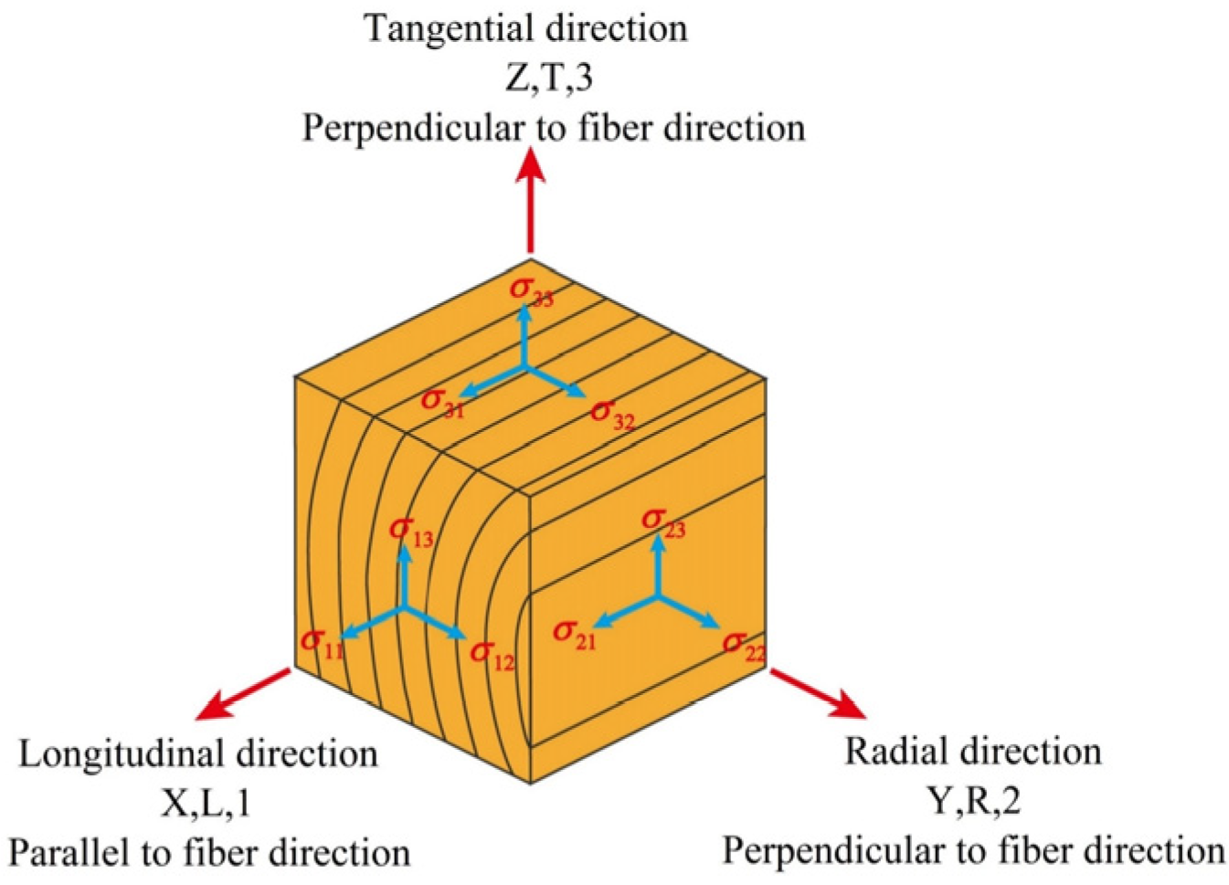
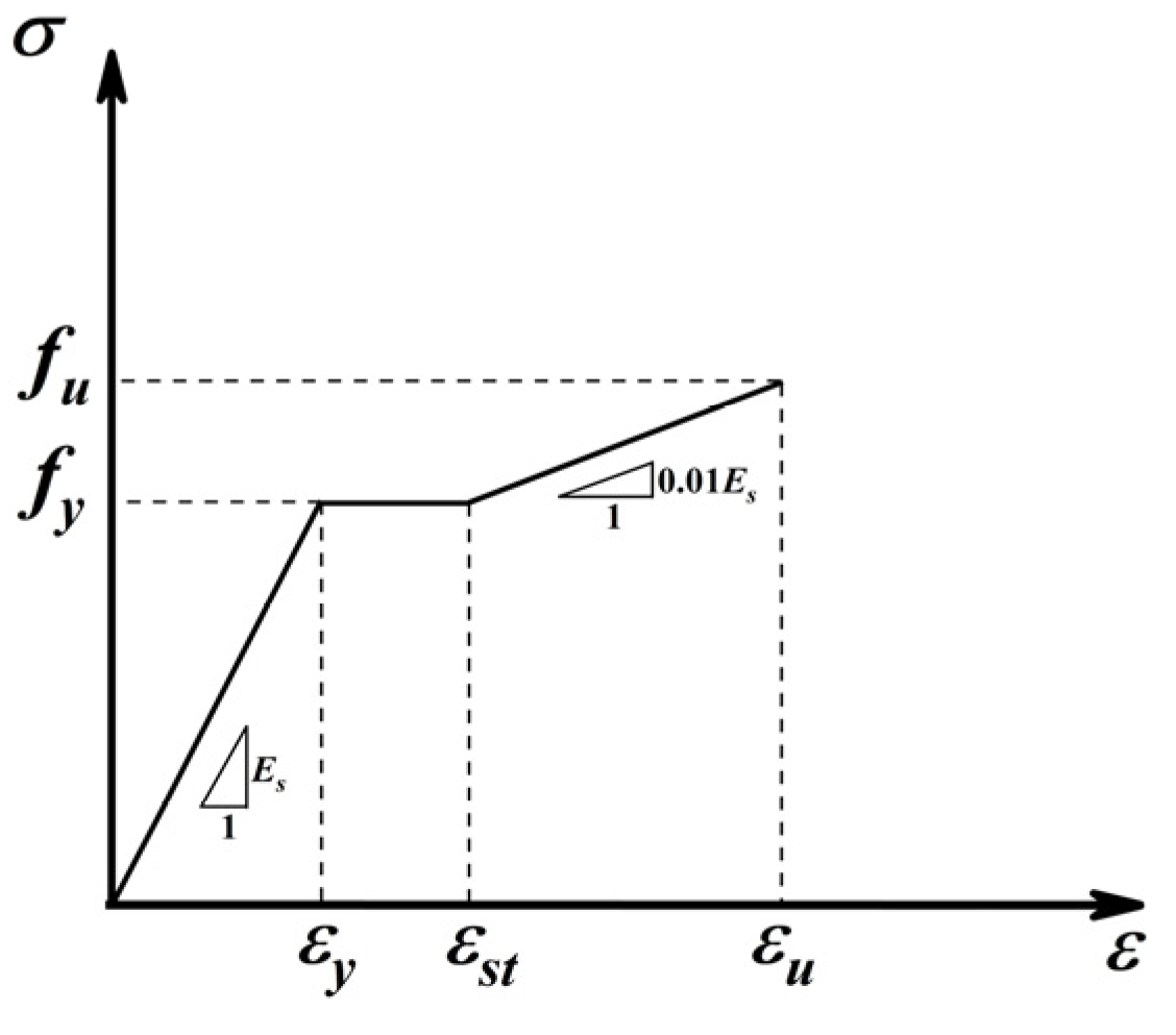
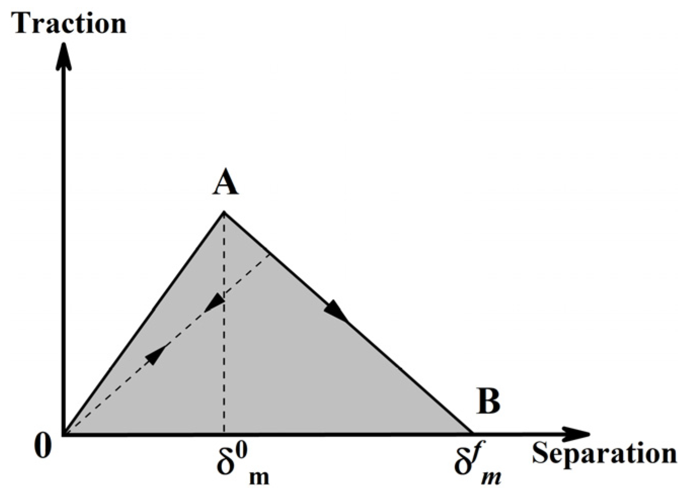
2.1. Material Properties

As shown in Figure 4, wood is an orthotopically anisotropic fibrous material that exhibits widely differing mechanical properties parallel and perpendicular to the fiber direction. However, wood has similar mechanical properties in the tangential and radial directions and can be considered a transversely isotropic material. In addition, the quasi-brittle damage of wood in shear/tension is described by a bilinear model, including an initial elastic phase and a linear softening behavior (Figure 5a). Therefore, the elastoplastic hardening–softening model was used to describe the compression behavior of wood and simplify the plastic damage of wood under compression (Figure 5b). The VUMAT subroutine of ABAQUS through Fortran was called to achieve the definition of the complex materials of glued laminated timber (GLT) and laminated veneer wood (LVL); the basic material parameters [21,22] are shown in Table 1 and Table 2.
CFTWS, bolts, and screws were modeled using a multilinear isotropic strengthening model, as shown in Figure 6. Considered an ideal elastoplastic model intrinsic relationship, the classical Von-Mises yield criterion was used. The yield strength of the CFTWS was 284 MPa, the average yield strength of the bolts and screws was 502 MPa, the Poisson’s ratio was 0.31, and the modulus of elasticity was 2 × 10⁵ MPa.
Epoxy resin adhesive material properties were then modeled using the plasticity damage material model. As shown in Figure 7, the cohesive damage model was used to define the damage when the adhesive layer is in operation, and the basic mechanical parameters of the material are shown by Ref. [23] in Table 3.

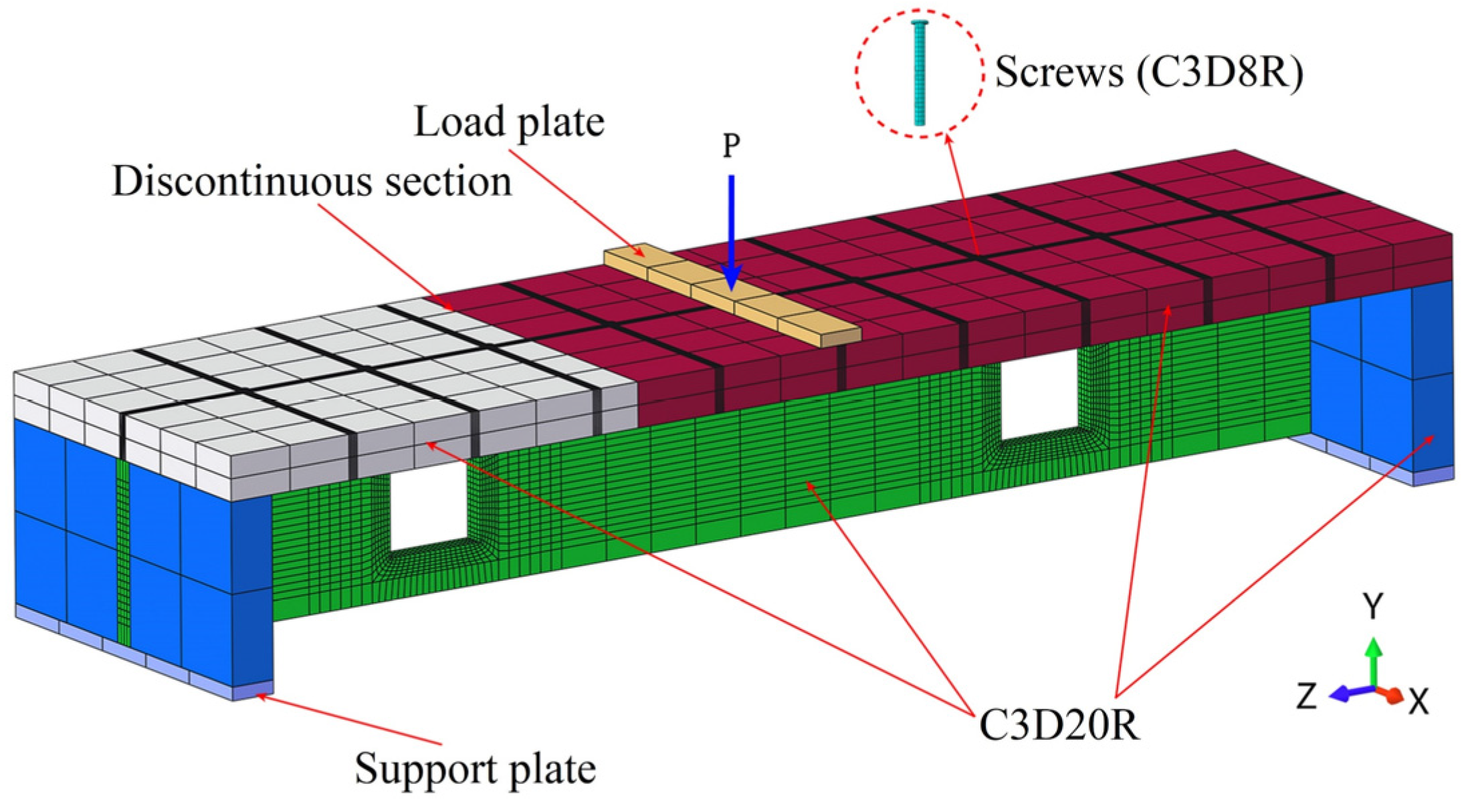
2.2. Mesh Division and Boundary Conditions

The overall mesh division was 100 mm in size, and the web-opening area and bolted cells were locally refined; the finite element model is shown in Figure 8. For the nonlinear analysis of the wood composite beams, materials such as steel were used with eight-node linear C3D8R reduced integral cells, and CLT and LVL were used with twenty-node C3D20R reduced integral cells. Rigid plates were set at the loading point and each end of the composite beam to match the actual boundary conditions more closely and to prevent stress concentrations resulting in convergence difficulties.
During the test, the plates and wood composite beams, the CLT flanges, and the upper surfaces of the stiffening ribs were in hard contact in a perpendicular direction and in friction contact in a tangential direction, where the friction coefficients of the wood–wood and steel–wood contact surfaces were set to 0.45 and 0.3. To enable the synergistic deformation of the screw and CLT/LVL, the constraint type of “embedded region” was used, and the stiffening ribs and LVL were set as discrete “surface-to-surface” tie constraints.

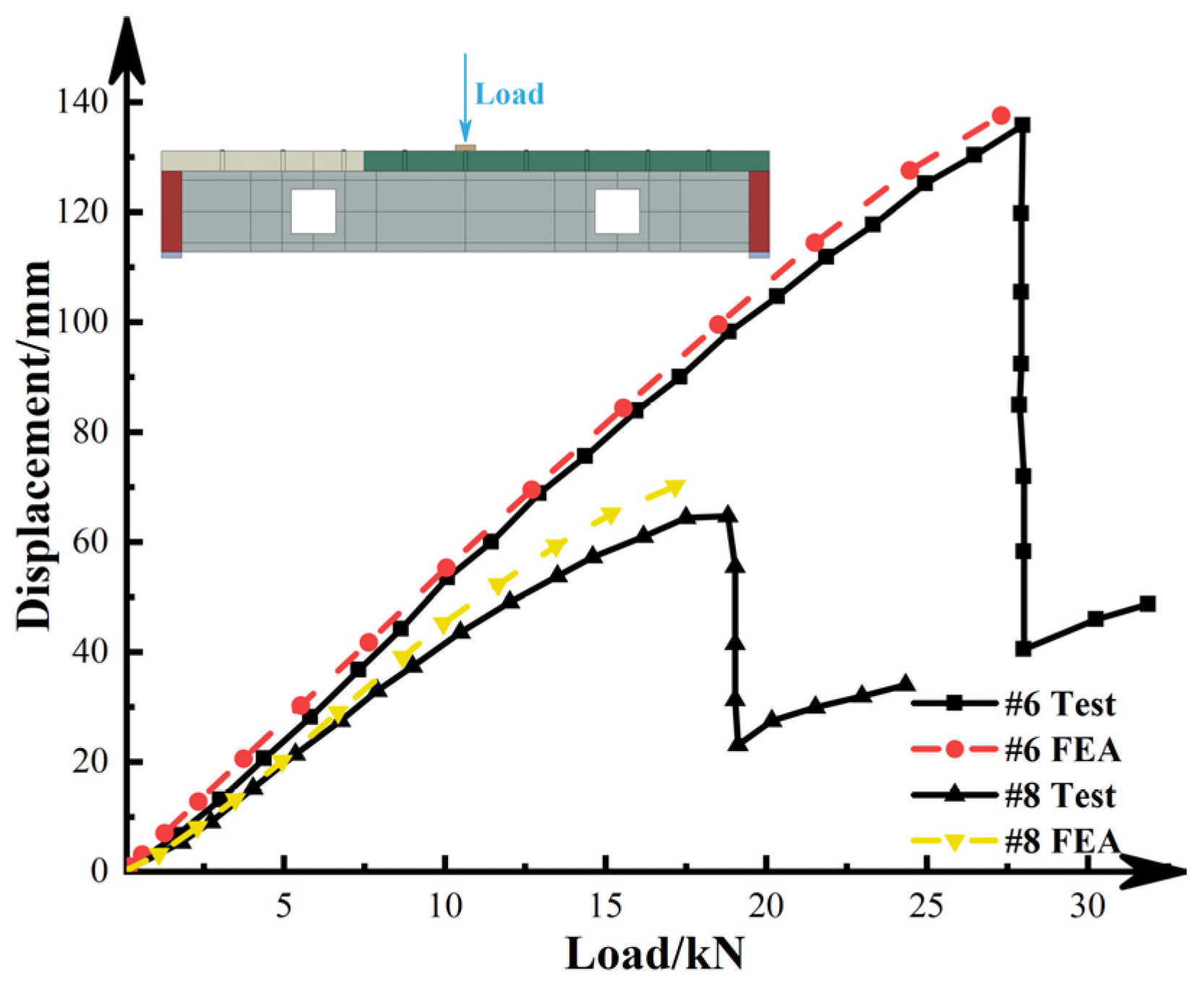
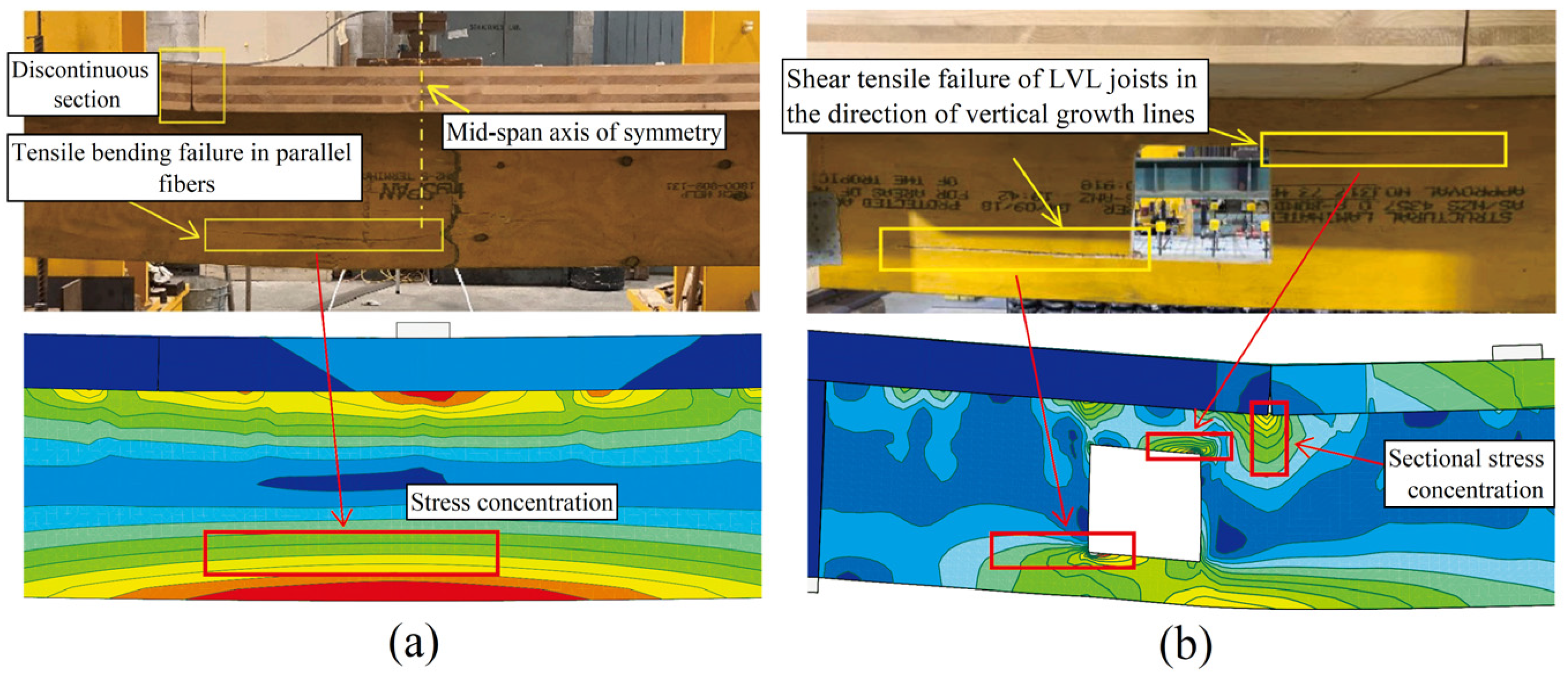
2.3. Comparison of Test and FEA Results

Karimi-Nobandegani [22] conducted an experimental study on wood composite beams with web opening and obtained the relevant load-carrying capacity and damage characteristics; the specimen parameters were mainly the shape of the slabs’ web-opening continuity/discontinuity. For verification of the reliability of the finite element model, nonlinear finite element analysis was carried out on 13 test specimens (#1~#13), and the comparison of the test and finite element results is shown in Table 4. Moreover, the load–displacement curves corresponding to representative specimens #6 and #8 were plotted, as shown in Figure 9. As can be seen, the load–displacement curve obtained from the test matches well with the finite element results, the stiffness and deformation capacity inaccuracies are small, and the inaccuracies of the ultimate bearing capacity are controlled within 6%, so engineering accuracy requirements are met.
Figure 10 compares the damage phenomena of the unopened beam (#6) and the rectangular web-opening beam (#8). It is observed that the discontinuous unopened wood composite beams (specimen #6) were characterized by typical bending damage in the mid-span area, and the mid-span webs were subjected to bending with a tensile fracture phenomenon in the direction of the grain (Figure 10a). Comparing the wood composite beams with rectangular openings (specimen #8), the cracks appeared at the tensile corner points of the opening and gradually expanded outwards. With the increase in load, the cracks expanded along the longitudinal direction until the whole specimen was damaged and lost its load-bearing capacity. The phenomenon obtained from the test is consistent with the finite element simulation results, and the damage pattern is similar, further verifying that the finite element analysis results are reliable.

3. Specimen Size and Reinforcement Measures

Since web opening reduces the stiffness and load-carrying capacity of wood composite beams, an effective reinforcement measure is needed in the area of the opening to compensate for the loss of mechanical properties caused by the opening. We investigated the effects of different reinforcement measures on the force performance of wood composite beams with discontinuous web openings. As shown in Figure 11, one unreinforced web-opening comparison beam (specimen #8) was set up. Another six specimens were designed, corresponding to six different reinforcement measures: specimens B1 and B2 were bolted and screwed to connectors to increase the strength of the connection between the web and the flange to achieve the effect of reinforcement, and a 2 mm thin steel spacer was set at the upper connection of the flange of specimen B1 to prevent stress concentration. Specimens B3~B6 were equipped with plywood and CFTWS to improve the flexural stiffness of the opening area to achieve the reinforcement effect, and different connection methods (epoxy resin and bolts) were considered to ensure the effective connection of the reinforcement components with the web-opening wood composite beams, as shown in Figure 12. The finite element models are all meshed with solid cells and hexahedral swept meshing, and the areas near the rectangular opening area and the reinforcement components were mesh-refined to obtain more accurate calculation results.

4. Analysis of Results

4.1. Bearing and Deformation Capacity

Referring to the GB/50005-2017 Standard for Design of Timber Structures [24], when the deflection in the span of the beam is L/250, the beam structure reaches the limit state of normal use (i.e., the beam is no longer suitable for the use of the demand after exceeding the deflection limit), and the load value corresponding to this time is the allowable bearing capacity. The allowable and ultimate bearing capacities (load value at beam failure) of the specimens with different reinforcement measures are shown in Table 5. As can be seen, all six reinforcement measures can improve the bearing capacity of wood composite beams with web openings. Among them, the reinforcements with better bearing capacity were bolts–CFTWS (specimen B5) and bolts–epoxy–CFTWS (specimen B6), with an improvement of 15 and 21%, illustrating that the CFTWS can form an effective combination action when tightly connected with the LVL web, which improves the bearing capacity in the open area. The lowest bearing capacity was for prestressing bolts (specimen B1), with an improvement of only 3%.
Figure 13 shows the displacement curves of each specimen along the beam length direction under different loads. Figure 13a shows that when each specimen beam reached the maximum allowable deflection at mid-span, the deflection curves of each specimen beam were adversely affected by the opening, and all of them showed some abrupt changes in the opening area. Among them, specimen #8 had the largest weakening of the cross-section stiffness in the opening area due to the unset reinforcement measures, resulting in the most significant abrupt change in the deflection curve; specimen B6 had the smallest abrupt change in the deflection curve, which indicates that the reinforcement of bolts–epoxy–CFTWS had the best reinforcement effect on the cross-section stiffness of the opening area, as the composite beam reached the ultimate load (Figure 13b). Unreinforced specimen #8 had the lowest deflection corresponding to the occurrence of damage. The overall curve of the composite beam specimens with reinforcement measures is relatively uniform, although there is still a certain degree of abrupt change, indicating that the reinforcement measures effectively improved the deformation capacity of the wood composite beams in the opening cross-section. The reinforcement with the best effect on the increase in deformation capacity was bolts–CFTWS (specimen B5), followed by bolts–epoxy–CFTWS (specimen B6), with an improvement of 44% versus 39%, respectively. This 1is mainly due to the CFTWS limiting the occurrence of deformation damage in the opening area, improving the overall structure’s deformation capacity.

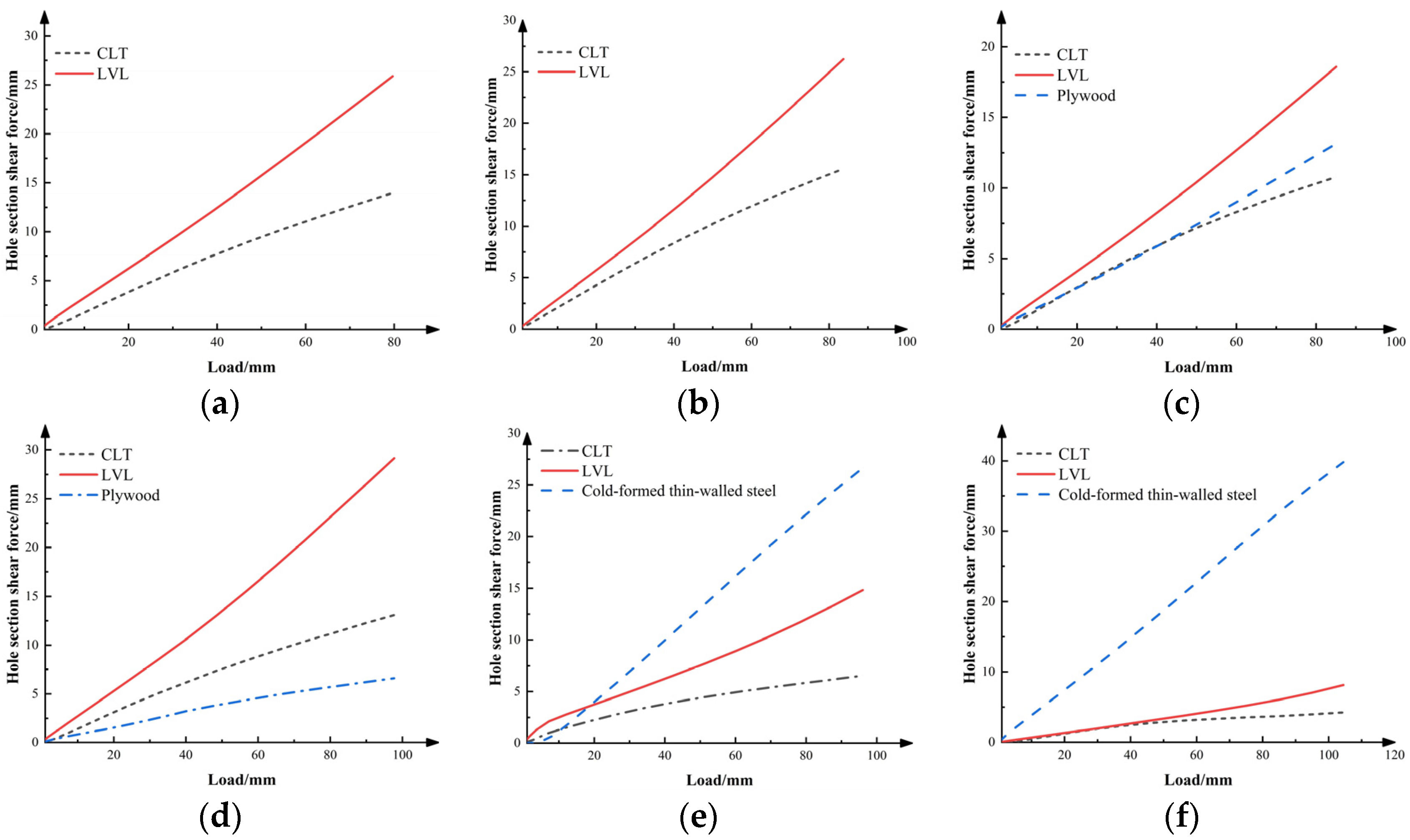
4.2. Shear Analysis of the Opening Area

The purpose of setting reinforcement measures is to increase the stiffness in the opening area, to help take up the shear forces in the opening section area, and to improve the overall working performance of the web-opening wood composite beams. The distribution of shear values in each part of the opening area is shown in Table 6. As can be seen, after reinforcement, the distribution of shear force in each part of the opening section becomes more uniform; specimens B1 and B2 increased their bearing capacity by 28%~34% by reinforcing the interconnection between the CLT flanges and the LVL webs. Specimens B3 and B4, in turn, effectively increased the shear bearing capacity of the composite beams by 34%–47% by using plywood to carry 14%–31% of the total shear force in the opening area. In addition, using CFTWS to reinforce the opening area (specimens B5 and B6) increased the ultimate bearing capacity by 53%–59%, whereas the CFTWS carried 55%–76% of the total shear force in the opening area.
Figure 14 shows the trend in the shear force distribution of each part during the loading process of the opening area. It can be seen that by enhancing the connection performance between the parts, a good combination can be formed, which is conducive to improving the shear performance of the opening section. The distribution of shear force in the opening area is redistributed using different methods to connect plywood and wood composite beams. When used as a connector, the epoxy can help the LVL web to carry more shear force, but the help in the ultimate bearing capacity is slightly lower than that of the bolts. Comparing Figure 14e,f, it can be seen that the distribution of internal forces in each part of the structure has completely changed after the use of CFTWS in the web of wood composite beams. In specimen B5 compared with specimen B6, the large difference in stiffness between the LVL web and reinforcement component measures and the discontinuity of the connection resulted in the pre-shear force being mainly borne by the web. After the load increase, the increased deformation of the opening area changed the shear transfer path, and the shear force was finally transferred to the CFTWS through the bolts.

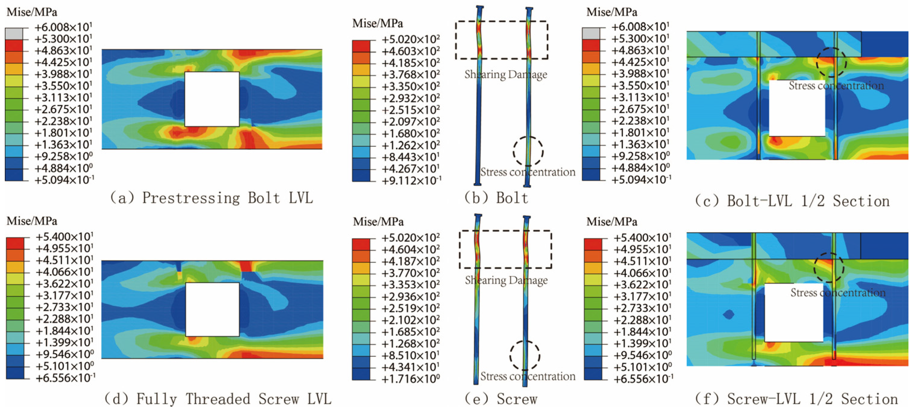
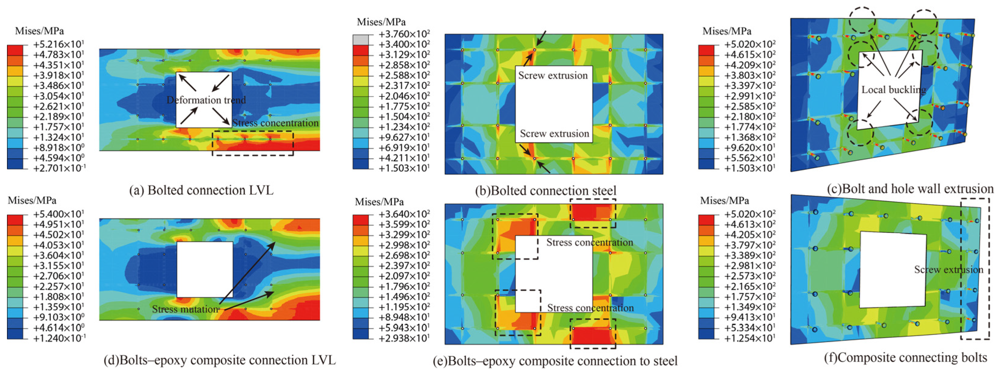
4.3. Analysis of Bolt and Screw Reinforcement Effect

The role of bolts and screws is mainly to increase the strength of the connection between the flange and the web, to counteract the shear, tensile stresses generated in the longitudinal direction in the LVL web under force, and to inhibit the occurrence of longitudinal cracks in the opening area, as shown in Figure 10b. Prestressing bolts mainly rely on prestressing to increase frictional occlusion with the wood and, to some extent, take up some of the longitudinal tensile stresses in the opening area while ensuring a tight fit between the CLT flanges and the LVL webs (Figure 15c). Fully threaded screws mainly rely on the threads to increase mechanical occlusion with the wood aperture wall and are more integral than the bolts. The end of the screw is reserved 20 mm from the bottom of the LVL web opening to avoid stress concentration in the open area (Figure 15f). Both can help inhibit the diagonal tensile deformation of the composite beam by embedding it inside the composite beam. As visible in Figure 15b,e, there is obvious shear deformation and misalignment at the interface between the CLT flange and LVL web at the upper end of the bolt and screw. Especially at the lower end near the discontinuous surface, the stress concentration is obvious due to the effect of opening deformation and hole wall extrusion. With the increase in load reaching the critical value, the cracks at the tensile corner points of the rectangular opening gradually expanded (Figure 15a,d). Although the two internal reinforcement measures could not inhibit the opening cracks’ generation, the cracks’ longitudinal development was controlled to a certain extent.

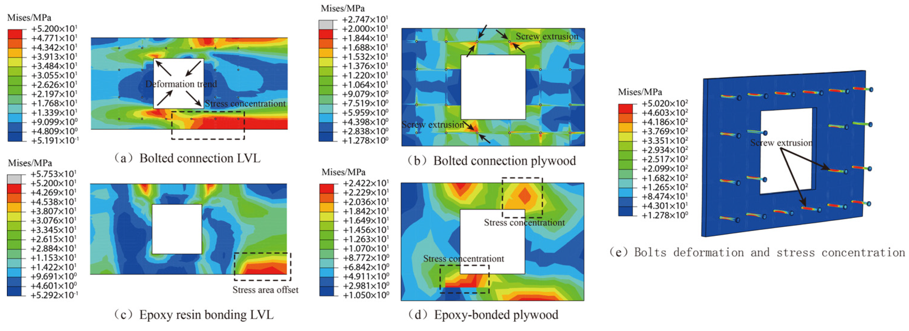
4.4. Analysis of Plywood Reinforcement Effect

Two types of connections, structural adhesive and bolts, were used for the plywood reinforcement, and the corresponding stresses are shown in Figure 16. As shown in Figure 16a, when the bolted connection is used, owing to the discontinuous contact between the plywood and the LVL web, a shear crack is generated at the lower left corner of the aperture. As the load increases, the LVL web deforms, and the internal force of the composite beam is transferred to the plywood through the bolts; they start to bear forces in concert (Figure 16b,e). The bolts, LVL web, and plywood experienced mutual extrusion, and an obvious stress discontinuity and concentration phenomenon appeared. When an epoxy resin adhesive connection is used, the increase in the integrity of the plywood and LVL web can improve the synergistic deformation of the structure, which provides a new force transfer path for the internal force in the opening area. However, the ductility of the structural adhesive connection is relatively poor [8]. As seen in Figure 16c,d, the plywood replaces the LVL web to bear part of the load, showing similar continuity stress distribution and significant deformation as the surface of the unreinforced LVL web, which effectively retards the generation and development of the cracks coming out of the opening corners. Now, the stress concentration area is shifted to the mid-span, and the structure undergoes the common mid-span bending and tensile damage.

4.5. Analysis of CFTWS Reinforcement Effect

CFTWS reinforcement was used with 2 mm thick cold-formed thin-walled sections (the same dimensions as plywood). From Figure 17, it can be seen that the connection method has a significant effect on the synergistic stresses of the two materials. Observations Figure 17a–c show that when the composite beam is connected only by bolts, the lower end of the LVL web shows obvious tensile stress damage phenomena with large top and bottom sides and a small center, and there is a stress concentration area of the section and bolts caused by extrusion. As the load value reaches the yield stress of the section, local buckling occurs near the opening. The composite beam is connected by an epoxy–bolt composite connection; the steel section and LVL web form an effective combined action in the opening area and are jointly loaded due to the assurance of continuity of the contact surface and uniformity of the stress transfer. Figure 17d,f show that CFTWSs have higher stiffness and smaller deformation than plywood. When the CFTWS and LVL web are in full contact, the internal force of the composite beam is first transferred by the CFTWS, and there is an obvious stress fault at the LVL web and the end of the section near the span axis. The bonding of the structural adhesive then reduces the shear deformation of the bolts caused by the misalignment of the CFTWS and the LVL web. The whole beams finally failed in the center of the span region in bending and tensile damage, and the structure was declared to have failed.

5. Conclusions

This study analyzes the mechanical properties of discontinuous timber beams with web openings and six different reinforcement measures set for the opening area to expand the use of timber beams in practical engineering scenarios and the scope of application. The conclusions are as follows:
  • The six types of reinforcement measures set up in the opening area can make up for the loss of bearing capacity and deformation capacity caused by the web opening, and the main damage modes of the structure affected by the reinforcement measures are shown as the shear damage in the opening area and the bending and stretching damage at the bottom of the beam in the middle of the span.
  • Bolts and screws, when used as reinforcement measures, cannot avoid the generation of opening cracks, although they can help transfer shear stresses to a certain extent and increase the ultimate bearing capacity by 29%, as well as inhibit the longitudinal development of cracks.
  • The composite beams showed the best co-deformation with plywood reinforcement. The plywood helps to carry 14% to 31% of the shear value, which ultimately improves the ultimate bearing capacity of the wood composite beams by 33% to 47%, but the structure is prone to brittle damage in the opening area.
  • The effectiveness of CFTWS reinforcement is directly related to the type of connection. CFTWSs are susceptible to local buckling in the opening area when only bolted connections are used. The composite connection can effectively avoid local buckling, optimize the force transfer path, and help to bear 76% of the shear force value so that the ultimate bearing capacity and deformation capacity are increased by 59% and 39%, respectively. The bolts–epoxy–cold-formed thin-walled steel composite reinforcement was used to improve wood composite beams’ stiffness and bearing capacity with web openings.

Author Contributions

Conceptualization, H.W. and W.L.; methodology, Y.Y.; software, H.W.; validation, B.D. and Z.C.; formal analysis, H.W.; investigation, H.C.; resources, X.L.; data curation, H.W.; writing—original draft preparation, H.W.; writing—review and editing, H.W. and W.L.; visualization, Y.Y.; supervision, B.D.; project administration, H.W.; funding acquisition, W.L and B.D. All authors have read and agreed to the published version of the manuscript.

Funding

This research was funded by the National Natural Science Foundation of China, grant number 52268051, and Yunnan Provincial Department of Education Program, grant number 2023J0714.

Data Availability Statement

The data presented in this study are available on request from the corresponding author.

Acknowledgments

The support for this project is acknowledged with thanks.

Conflicts of Interest

The authors declare that they have no known competing financial interests or personal relationships that could have appeared to influence the work reported in this paper.

References

  1. Ramage, M.H.; Burridge, H.; Busse-Wicher, M.; Fereday, G.; Reynolds, T.; Shah, D.U.; Wu, G.; Yu, L.; Fleming, P.; Densley-Tingley, D.; et al. The Wood from the Trees: The Use of Timber in Construction. Renew. Sustain. Energy Rev. 2017, 68, 333–359. [Google Scholar] [CrossRef]
  2. Buchanan, A.H.; Levine, S.B. Wood-Based Building Materials and Atmospheric Carbon Emissions. Environ. Sci. Policy 1999, 2, 427–437. [Google Scholar] [CrossRef]
  3. Kamala, B.S.; Kumar, P.; Rao, R.V.; Sharma, S.N. Performance Test of Laminated Veneer Lumber (LVL) from Rubber Wood for Different Physical and Mechanical Properties. Holz Roh Werkst. 1999, 57, 114–116. [Google Scholar] [CrossRef]
  4. Issa, C.A.; Kmeid, Z. Advanced Wood Engineering: Glulam Beams. Constr. Build. Mater. 2005, 19, 99–106. [Google Scholar] [CrossRef]
  5. Yeoh, D.; Fragiacomo, M.; De Franceschi, M.; Heng Boon, K. State of the Art on Timber-Concrete Composite Structures: Literature Review. J. Struct. Eng. 2011, 137, 1085–1095. [Google Scholar] [CrossRef]
  6. Khorsandnia, N.; Valipour, H.; Schänzlin, J.; Crews, K. Experimental Investigations of Deconstructable Timber–Concrete Composite Beams. J. Struct. Eng. 2016, 142, 04016130. [Google Scholar] [CrossRef]
  7. Hassanieh, A.; Valipour, H.R.; Bradford, M.A. Experimental and Numerical Study of Steel-Timber Composite (STC) Beams. J. Constr. Steel Res. 2016, 122, 367–378. [Google Scholar] [CrossRef]
  8. Chien, T.-P.; Yang, T.-H.; Chang, F.-C. Flexural Performance of Built-Up Beams Made with Plantation Wood. Forests 2019, 10, 647. [Google Scholar] [CrossRef]
  9. Zhu, E.C.; Guan, Z.W.; Rodd, P.D.; Pope, D.J. Buckling of Oriented Strand Board Webbed Wood I-Joists. J. Struct. Eng. 2005, 131, 1629–1636. [Google Scholar] [CrossRef]
  10. Ghanbari-Ghazijahani, T.; Russo, T.; Valipour, H.R. Lightweight Timber I-Beams Reinforced by Composite Materials. Compos. Struct. 2020, 233, 111579. [Google Scholar] [CrossRef]
  11. Borri, A.; Corradi, M. Strengthening of Timber Beams with High Strength Steel Cords. Compos. Part B Eng. 2011, 42, 1480–1491. [Google Scholar] [CrossRef]
  12. Wu, H.; Liao, W.; Liu, D.; Zhou, X.; Chen, Z. Mechanical Properties of Composite Beams with Web Openings under Negative Bending Moments. Structures 2023, 58, 105394. [Google Scholar] [CrossRef]
  13. Zhou, X.; Liao, W.; Liu, D. Ultimate Bearing Capacity of Composite Beams with Reinforced Web Opening under Hogging Moment: Practical Calculation Method. Structures 2023, 47, 2531–2540. [Google Scholar] [CrossRef]
  14. Aicher, S.; Tapia, C. Novel Internally LVL-Reinforced Glued Laminated Timber Beams with Large Holes. Constr. Build. Mater. 2018, 169, 662–677. [Google Scholar] [CrossRef]
  15. Darwin, D.; Donahey, R.C. LRFD for Composite Beams with Unreinforced Web Openings. J. Struct. Eng. 1988, 114, 535–552. [Google Scholar] [CrossRef]
  16. Chen, G.; Li, H.; Zhou, T.; Li, C.; Song, Y.; Xu, R. Experimental Evaluation on Mechanical Performance of OSB Webbed Parallel Strand Bamboo I-Joist with Holes in the Web. Constr. Build. Mater. 2015, 101, 91–98. [Google Scholar] [CrossRef]
  17. Hallstriim, S. Glass Fibre Reinforced Holes in Laminated Timber Beams. Wood Sci. Technol. 1996, 30, 323–337. [Google Scholar]
  18. Ardalany, M.; Fragiacomo, M.; Moss, P.; Deam, B. An Analytical Model for Design of Reinforcement around Holes in Laminated Veneer Lumber (LVL) Beams. Mater. Struct. 2013, 46, 1811–1831. [Google Scholar] [CrossRef]
  19. Ardalany, M.; Fragiacomo, M.; Deam, B.; Crews, K. Analytical Cracking Load Estimation of Laminated Veneer Lumber (LVL) Beams with Holes. Eur. J. Wood Wood Prod. 2013, 71, 37–48. [Google Scholar] [CrossRef]
  20. Leichti, R.J.; Falk, R.H.; Laufenberg, T.L. Prefabricated Wood I-Joists: An Industry Overview. For. Prod. J. 1990, 40, 15–20. [Google Scholar]
  21. Karimi-Nobandegani, A.; Valipour, H. Timber Beams with Openings: Laboratory Testing and Nonlocal Finite Element Modelling. Eng. Struct. 2021, 245, 112867. [Google Scholar] [CrossRef]
  22. Karimi-Nobandegani, A.; Valipour, H. Effect of Web Openings on Timber Composite Beams: Testing and Analytical Modelling. Eng. Struct. 2022, 256, 114064. [Google Scholar] [CrossRef]
  23. Xu, D.; Li, Y.; Zhang, Z. The Application of Cohesive-Zone Models in Deformation Analysis of Steel Bamboo Composite Beams. China For. Prod. Ind. 2018, 45, 42–47. [Google Scholar] [CrossRef]
  24. GB 5005-2017; Standard for Design of Timber Structures. Standards Press of China: Beijing, China, 2017.
Figure 1. Piping equipment through web opening.
Forests 15 01318 g001
Figure 2. Opening crack generation and expansion.
Forests 15 01318 g002
Figure 3. Wood composite beams with web-opening and discontinuous sections.
Forests 15 01318 g003
Figure 4. Three-dimensional stress components and orthogonal principal directions in wood.
Forests 15 01318 g004
Figure 5. Uniaxial stress–strain curves of wood in (a) compression and (b) shear/tension.
Forests 15 01318 g005
Figure 6. Multilinear isotropic reinforced stress–strain curve.
Forests 15 01318 g006
Figure 7. Stress–strain curve for cohesive model.
Forests 15 01318 g007
Figure 8. Grid and cell division.
Forests 15 01318 g008
Figure 9. Load–displacement curves.
Forests 15 01318 g009
Figure 10. Comparison of failure characteristics of specimens. (a)Mid–span tensile bending damage; (b) Rectangular orifice Shear tensile damage.
Forests 15 01318 g010
Figure 11. Specimen geometry.
Forests 15 01318 g011
Figure 12. Schematic diagram of different reinforcement measures.
Forests 15 01318 g012
Figure 13. Beam length deflection curves for different states. (a) Deflection curves at allowable deflection; (b) Deflection curves under ultimate loads.
Forests 15 01318 g013
Figure 14. Shear distribution in the orifice reinforcement section. (a) Prestressing bolt; (b) Fully threaded screw; (c) Epoxy resin–plywood; (d) Bolts–plywood; (e) Bolts–CFTWS; (f) Bolts–epoxy–CFTWS.
Forests 15 01318 g014
Figure 15. Stress distribution of bolt and screw reinforcement.
Forests 15 01318 g015
Figure 16. Stress distribution in plywood reinforcement.
Forests 15 01318 g016
Figure 17. Stress distribution in CFTWS reinforcement.
Forests 15 01318 g017
Table 1. Mechanical properties of wood CLT.
E1/MpaE2/MpaE3/MpaG12/MpaG13/MpaG23/MpaV12V13V23
11,000370730690690500.480.480.22
Subscript direction 1 is the parallel fiber direction; E: modulus of elasticity; G: shear modulus; V: Poisson’s ratio.
Table 2. Mechanical properties of wood LVL.
Parallel Fiber Direction (MPa)Vertical Fiber Direction (MPa)Shear Modulus and Strength (MPa)Fracture Energy (N/mm)
E1 f 1 t f 1 c E2,3 f 2,3 t f 2,3 c G12,13G23fvGF,2GF,12
13,20030424002.0212660504.60.71.2
ft, fc, fv indicate tensile strength, compressive strength, and shear strength, respectively.
Table 3. Material properties of epoxy resin adhesive.
Es/MpaG1/MpaG2/Mpa σ n m a x /Mpa τ s m a x /Mpa τ t m a x /Mpa
150015001500
GN/(J·mm−2)GS/(J·mm−2)GT/(J·mm−2)13.613.713.7
0.320.410.41
σ n m a x , τ s m a x , τ t m a x indicate the maximum stress in the normal, tangential 1, and tangential 2 directions of the unit.
Table 4. Experimental and finite element comparison results.
NOUltimate Load Capacity/kNInaccuracies/%Limit Displacement/mmInaccuracies/%
TestFEATestFEA
#144.5845.522.135.4736.141.9
#240.6641.883.035.9836.842.4
#387.3590.233.337.9439.083.0
#487.0888.471.638.5039.041.4
#5182.90179.61−1.838.0837.20−2.3
#6136.65137.610.727.8428.151.1
#766.6965.16−2.318.5218.24−1.5
#867.3370.094.117.9118.503.3
#9224.64233.403.925.2426.304.2
#1076.7580.134.413.5614.315.5
#1181.5482.030.611.2611.451.7
#1234.3635.944.610.2910.724.2
#1335.5436.462.613.5113.782.0
FEA: finite element analysis.
Table 5. Allowable and ultimate load capacity of specimens with different reinforcement methods/kN.
NOReinforcement MeasuresFaFai/Fa#8FuFui/Fu#8
#8/49.071.0067.331.00
B1Prestressing bolt50.491.0386.311.28
B2Fully threaded screw52.771.0889.961.29
B3Epoxy resin–plywood53.791.1089.871.33
B4Bolts–plywood52.581.0798.971.47
B5Bolts–CFTWS56.191.15102.861.53
B6Bolts–epoxy–CFTWS59.221.21107.181.59
Fa: allowable bearing capacity; Fu: ultimate bearing capacity.
Table 6. Cross-sectional shear distribution in the opening area/kN.
NOReinforcement MethodFuVuVCLTVLVLVplateVCLT/VGVLVL/VGVplate/VG
#8/67.3329.468.2521.21-0.280.72-
B1Prestressing bolt86.3139.8313.9425.89-0.350.65-
B2Fully threaded screw89.9641.8415.6026.24-0.370.63-
B3Epoxy resin–plywood89.8742.5110.7818.5813.150.250.440.31
B4Bolts–plywood98.9748.8613.0829.186.610.270.600.14
B5Bolts–CFTWS102.8649.916.9915.4727.450.140.310.55
B6Bolts–epoxy–CFTWS107.1852.224.268.1439.830.080.160.76
Fu: ultimate carrying capacity; Vu: total shear on reinforced side; VCLT: shear forces borne by CLT flanges; VLVL: shear forces borne by LVL webs; Vplate: shear forces borne by plywood/CFTWS.
Disclaimer/Publisher’s Note: The statements, opinions and data contained in all publications are solely those of the individual author(s) and contributor(s) and not of MDPI and/or the editor(s). MDPI and/or the editor(s) disclaim responsibility for any injury to people or property resulting from any ideas, methods, instructions or products referred to in the content.

