Article

Effect of Different-Diameter Wooden Pins on Mechanical Properties of Triangular Girder Trusses

1
College of Materials Science and Engineering, Nanjing Forestry University, Nanjing 210037, China
2
Nanhang Jincheng College, Nanjing 211156, China
*
Author to whom correspondence should be addressed.
Forests 2024, 15(9), 1675; https://doi.org/10.3390/f15091675
Submission received: 24 August 2024 / Revised: 16 September 2024 / Accepted: 17 September 2024 / Published: 23 September 2024
(This article belongs to the Section Wood Science and Forest Products)

Abstract

:
With the expanding application of lightweight wooden structures in modern construction, the load-bearing capacity of ordinary triangular single-span wooden trusses limits the applicability of lightweight wooden structures. As a result, triangular multi-span wooden trusses have emerged to replace single-span wooden trusses. In practice, multi-span wooden trusses are composed of multiple single-span lightweight wooden trusses, with connections between members using metal plates, a field that has been relatively well researched. However, connections between spans are primarily made with nails in actual engineering, and there has been little research on the use of wooden pins to connect multi-span wooden trusses. To study the mechanical performance of multi-span wooden trusses connected by wooden pins, this paper innovatively combines existing equipment with a self-designed pulley assembly device to conduct a continuous static full-scale loading test on double-span wooden trusses connected by wooden pins of three different diameters. We comprehensively evaluate which type of wooden pin is more suitable for triangular multi-span wooden trusses. The results indicate that the 16 mm diameter wooden pin provides the best energy dissipation performance for connected beam trusses. The 20 mm diameter wooden pin offers the best performance stability. The 20 mm diameter wooden pin also demonstrates a good load-bearing capacity and resistance to deformation. Overall, the 20 mm diameter wooden pin exhibits the best connection performance in triangular beam trusses.

1. Introduction

In recent years, China has been vigorously promoting the construction of ecological buildings. As a renewable resource, wood has significant advantages in terms of energy conservation, emission reduction, and environmental protection, alleviating the pressure on construction resources and achieving material recycling and sustainable development [1]. Wooden structures are an important type of ecological building. Since September 2015, national policies have recommended the development of modern wooden structures tailored to local conditions, particularly for government-funded public buildings such as schools, nurseries, elderly residences, and landscape gardens [2]. It is evident that the promotion and application of wooden structures have increasingly gained widespread support in society.
Lightweight wooden trusses, as one of the main supporting components of lightweight wooden structures [3], are widely used. Currently, over 60% of residential buildings in North America use wooden trusses, and about 95% of new residential buildings in Canada adopt wooden trusses [4]. Moreover, wooden trusses are also widely utilized in Europe, Asia, and other regions. With the widespread application of lightweight wooden structures in the Chinese market, the use of wooden trusses in modern construction is becoming more extensive.
Currently, ordinary triangular single-span wooden trusses have limited load-bearing capacity, with the best performing lightweight wooden trusses (such as the Howe truss) having a span limitation of only 12 m [5]. This constraint restricts the application range of lightweight wooden roof and floor systems, which in turn hinders the promotion and development of lightweight wooden structures. The emergence of triangular multi-span wooden trusses effectively addresses this issue. By combining multiple ordinary triangular wooden trusses into a single structural component, the cross-sectional dimensions of the component can be increased to achieve better load-bearing capacity, resistance to deformation, and stability, thus accommodating larger span requirements [6,7,8,9].
Multi-span wooden trusses are composed of multiple single-span lightweight wooden trusses, with the connection nodes including connections between the members of single trusses and connections between the trusses themselves. Currently, the connections between members primarily use tooth plates, and research on these connections has matured. However, the connections between trusses primarily utilize nail connections in actual engineering, typically following the specifications for nail connections in mixed trusses as outlined in Chapter 6 of the Technical Specification for Lightweight Wooden Trusses [10].
Research on lightweight wooden trusses abroad primarily focuses on repair techniques, metal plate connections for single-span wooden trusses, lightweight wooden truss systems, and the stability of large-span wooden trusses [11,12,13,14,15,16,17]. The aim is to enhance the load-bearing capacity and ductility of wooden trusses while maintaining their light weight and sustainability through the use of traditional wood, metal plates, bolt connections, truss design, and composite materials. Stability studies of large-span wooden trusses mainly concentrate on numerical simulation analysis, connection node designs, and new reinforcement techniques, whereas there is almost no research addressing multi-span wooden trusses. Domestically, researchers such as Xu Xiaoliang [18], Shi Chao [4], Kuang Yi [19], and Huang Hao [20] have primarily concentrated on single-span wooden trusses. Che Yuke [21] conducted static loading tests on a Fink truss with a span of 4.8 m, studying the impacts of deformation, equivalent stress on the metal tooth plate, joint rotation, and truss failure modes. Professor Que Zeli’s team at Nanjing Forestry University, including Gao Yifan [22,23,24], has researched connection nodes in parallel chord multi-span wooden trusses; however, studies on wooden pin connections in multi-span wooden trusses are relatively scarce.
This paper innovatively integrates an existing microcomputer-controlled electro-hydraulic servo combination shear wall experimental system with a self-designed pulley loading device to conduct continuous static full-scale loading tests on double-span wooden trusses connected by wooden pins of three different diameters, in accordance with the “Standard for Testing Methods of Wood Structures” (GB/T 50329-2012) [25]. The experiments were carried out in three continuous loading phases: T1, T2, and T3. We conducted corresponding analyses of the truss’s load-bearing capacity, stiffness, stability, deformation, and energy dissipation performance, thereby investigating the overall performance of the three diameters of wooden pins in connecting multiple spans of wooden trusses. This enables a comprehensive evaluation of which type of wooden pin is most suitable for connecting triangular multi-span wooden trusses.

2. Materials and Methods
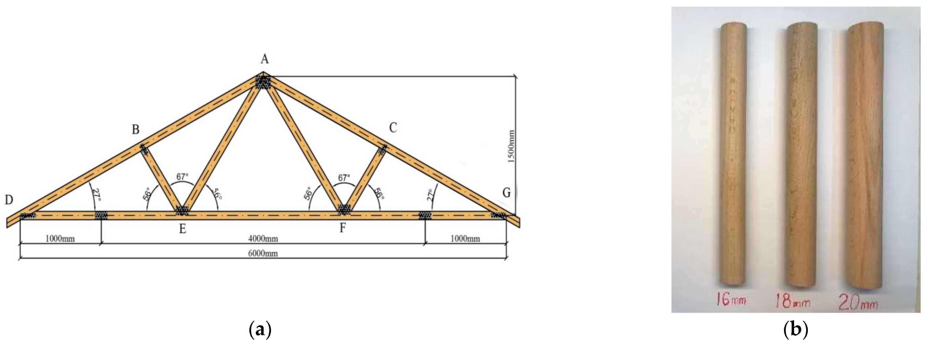
2.1. Materials

The tests used Fink wooden trusses with a span of 6 m and a height of 1.5 m (Figure 1a). The truss members were made from Russian larch with a cross-sectional size of 38 mm × 89 mm. The material parameters are shown in Table 1 [22]. The metal plates used were domestically produced galvanized plates with performance parameters listed in Table 2. The dowel material was beech wood (Figure 1b) with a length of 80 mm. The truss numbering and identifiers are shown in Table 3.

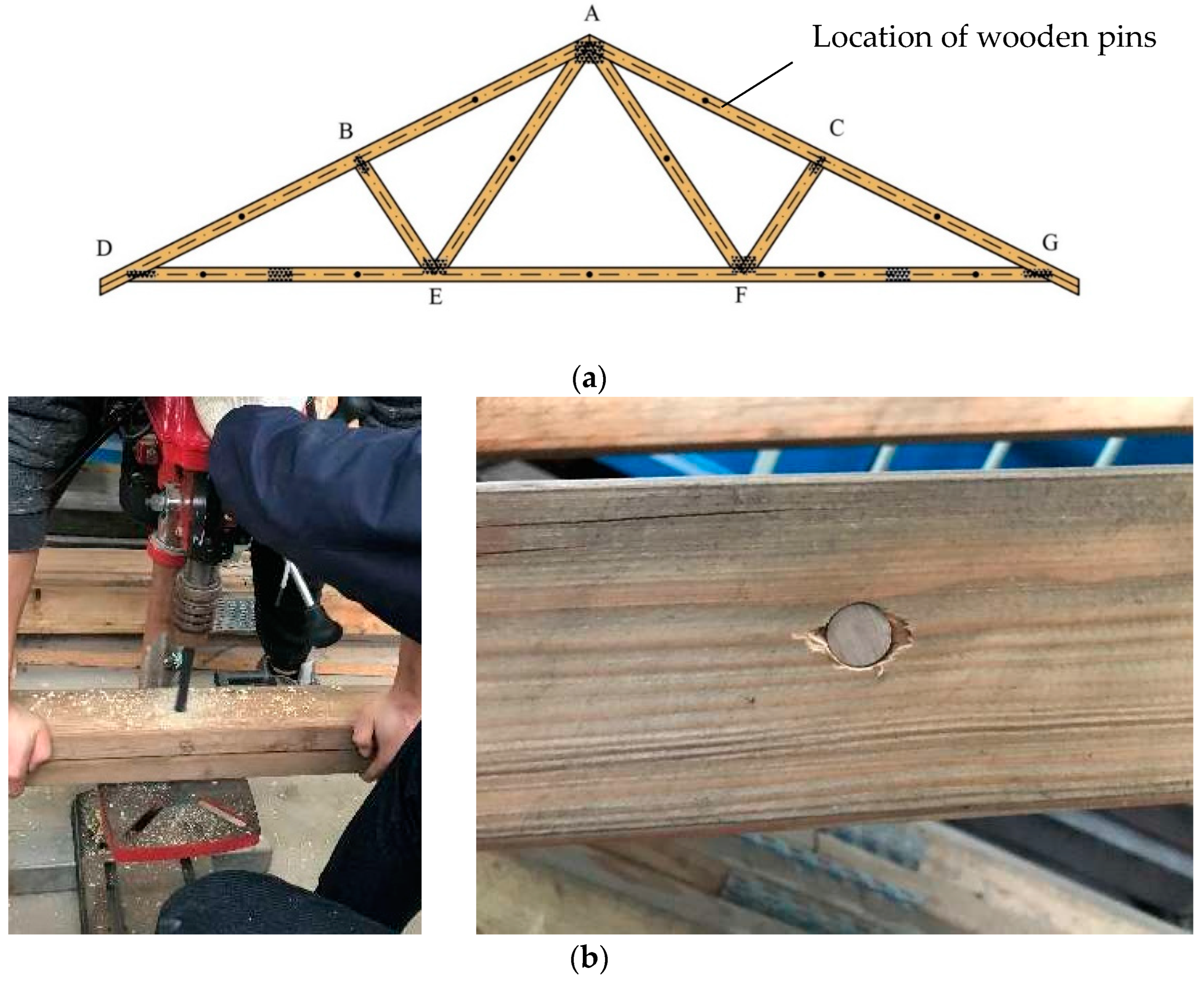
2.2. Sample Preparation

According to Article 6.2.12 of the “Technical Code for Lightweight Wooden Trusses” (JGJ/265-2012) [10], the multi-span wooden trusses were constructed by connecting single-span Fink wooden trusses with dowels.
The single-span wooden trusses used metal plates, which were manually positioned and pressed in with a pressure of 13 MPa. The multi-span wooden trusses were assembled by stacking two trusses and connecting them with dowels. The node positions (Figure 2a) were drilled with a drill to create holes 0.5 mm smaller in diameter than the dowels. The dowels were then inserted into these holes to form the nodes (Figure 2b).

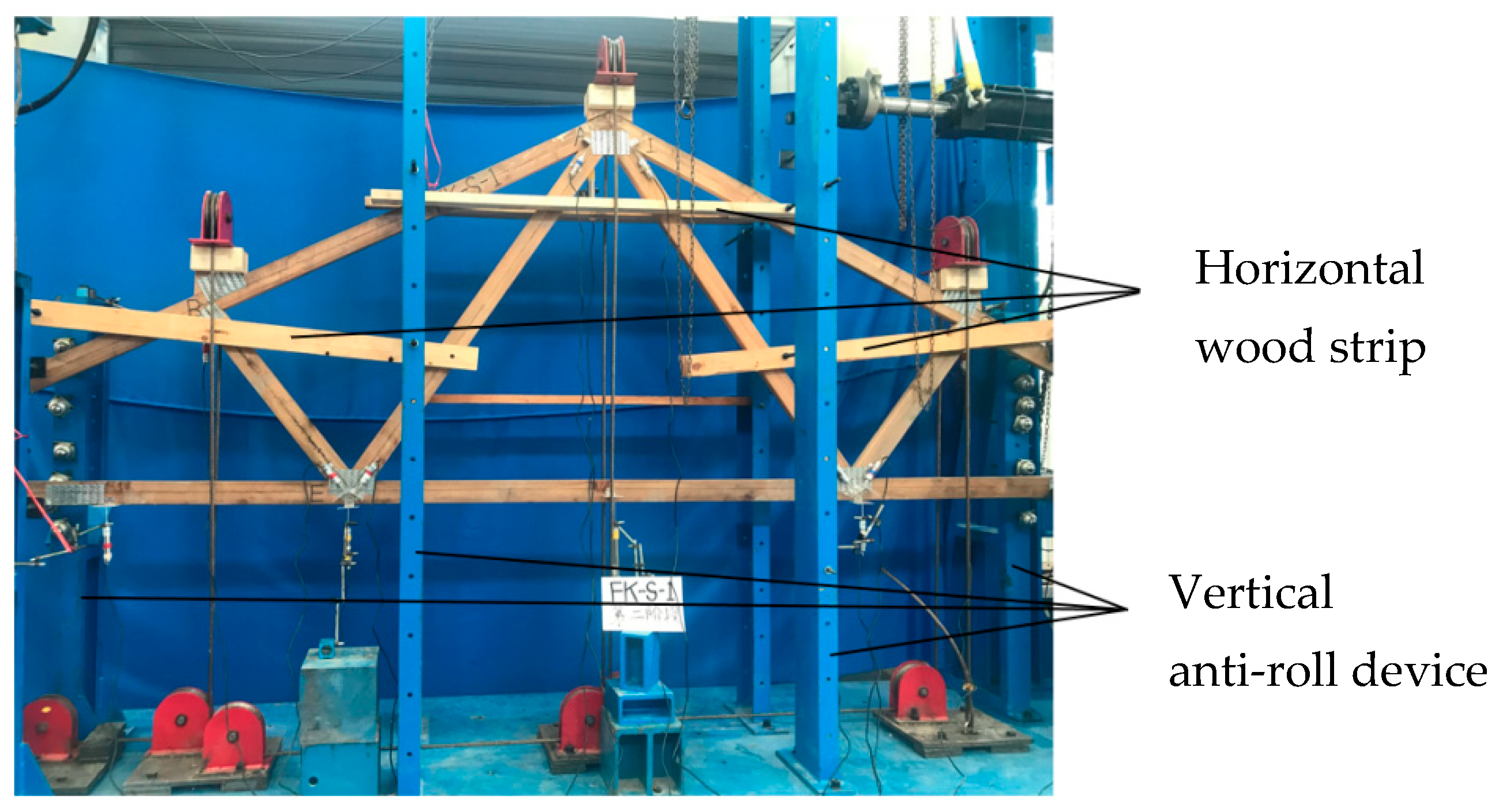
2.3. Loading System and Device

The tests followed the “Standard for Testing Methods of Timber Structures” GB/T50329 (2012) [25] truss layered loading test method. The test needs three nodes on the truss string static load, as the existing loading equipment microcomputer control electro-hydraulic servo, combined with the shear wall test system itself, does not have the conditions of the three loading heads. This test requires the design of a wooden truss-loading device (Figure 3) [26].
Due to the large span of the trusses and poor stability in the loading process, an anti-roll device is important for the loading of the wooden truss. Based on the laboratory conditions, a lateral support device (Figure 4) was designed to prevent tipping.

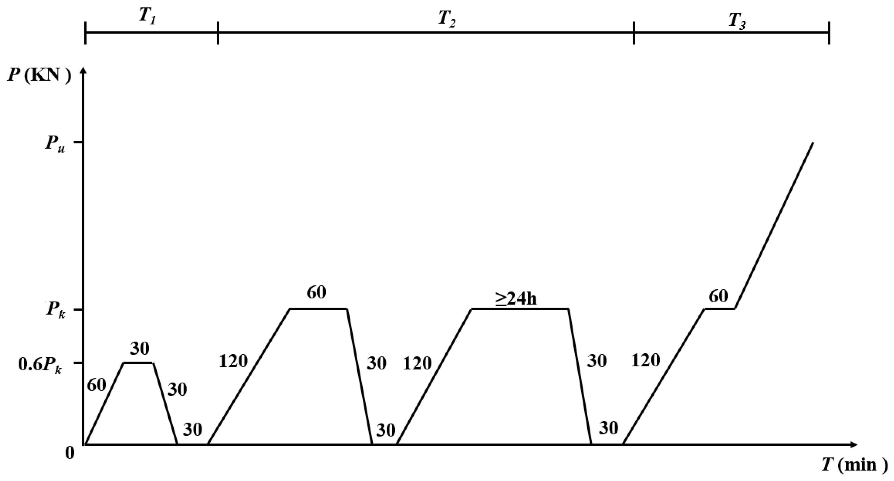
2.4. Loading Procedure

The truss was loaded according to the continuous loading system in 14.5.3 of the “Standard for Test Methods of Wood Structures” (GB/T50329-2012) [25]. Among them, Pk is calculated according to the “Code for the Design Loading of Building Structures” GB50009 (2012) (Standardization Administration of China, 2012) [27], and the result is Pk=4.6kN.
The loading process is divided into three stages (Figure 5): the pre-loading stage (T1), the standard loading stage (T2), and the destructive loading stage (T3).

3. Results and Discussion

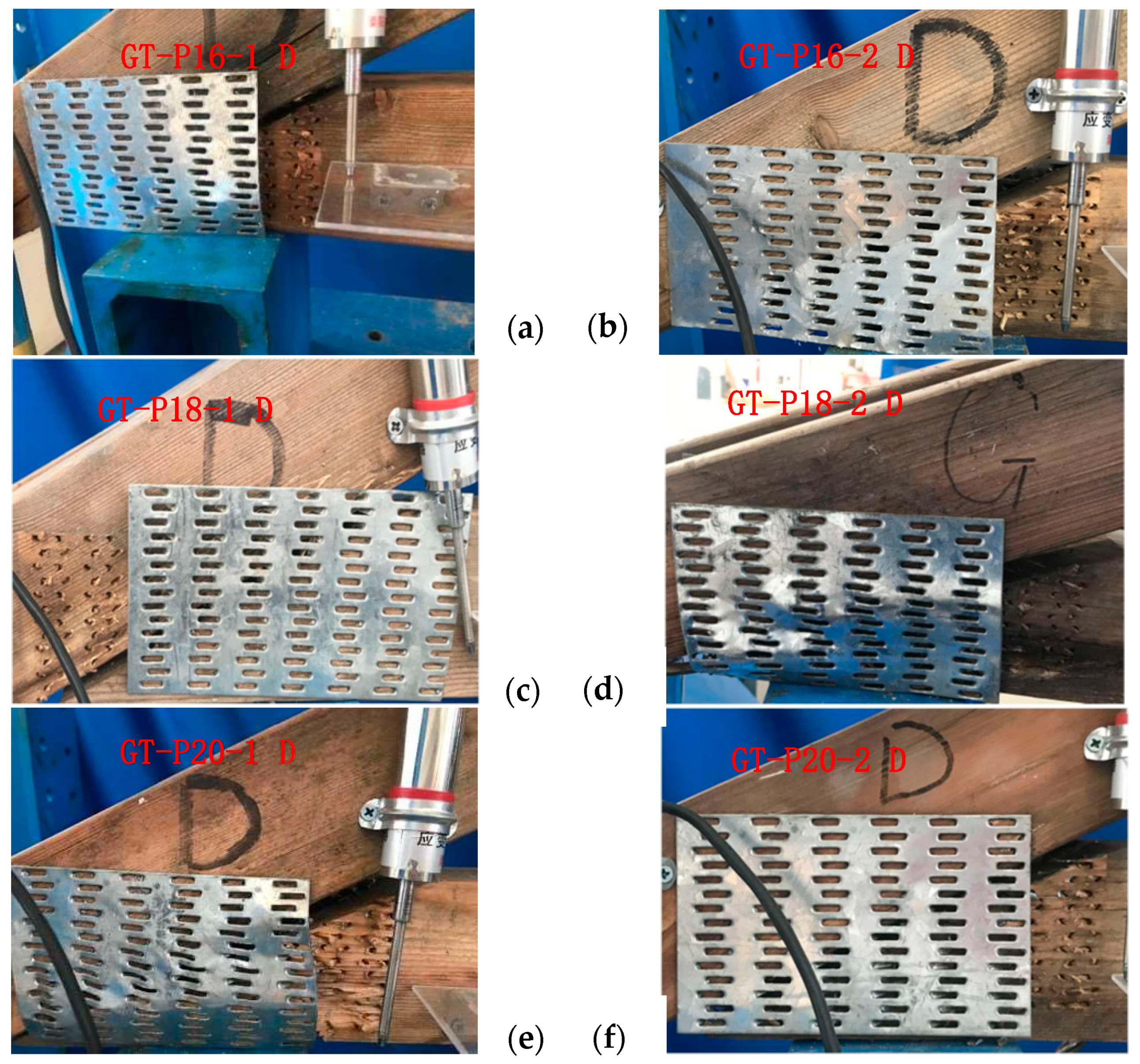
3.1. Analysis of Experimental Phenomena

During the preloading (T1) and standard loading (T2) stages, the double-span wooden trusses showed no significant damage. In the destructive (T3) stage, noticeable lateral tilting occurred. With the increase in load, severe twisting was observed at the nodes with metal plate teeth displacement and failure.
In the GT-P16-1 truss (Figure 6a), when the load increased to approximately 12.90 kN, minor tooth deformation occurred on the internal metal plates of both trusses and between the two single-span trusses. The load reached 19.26 kN when the D node experienced tooth failure. In the GT-P16-2 truss (Figure 6b), at a load of around 11.86 kN, minor tooth deformation was observed on the internal metal plates of both trusses and between the single-span trusses. At 15.04 kN, there was slight tooth failure at the D node, which ultimately failed at 19.26 kN.
Both specimens of the 16 mm dowel-connected double-span wooden trusses experienced tooth failure at the support nodes, indicating that the weak point in these trusses remains at the support nodes.
When the load of the GT-P18-1 truss increased to around 11.98 kN, slight tooth deformation occurred between the two single-span wooden trusses at the D node. As the load reached 13.16 kN, this developed into minor tooth disengagement. Eventually, when the load reached 18.14 kN, the tooth plate at the D node suffered from disengagement failure (Figure 6c).
In the case of the GT-P18-2 truss, when the load increased to approximately 12.48 kN, a slight bulging of the tooth plates at the D and G joints was observed. As the load continued to rise, the bulging phenomenon became increasingly severe. When the load reached 20.50 kN, the tooth plate at the G node experienced disengagement failure (Figure 6d).
When the load of the GT-P20-1 truss increased to around 14.40 kN, a slight bulging of the tooth plates at the D and G nodes was observed. As the load gradually increased, the bulging phenomenon intensified. At a load of 22.46 kN, both the inner and outer tooth plates at the D node disengaged from the lower chord member (Figure 6e). For the GT-P20-2 truss, a slight bulging of the tooth plate at the D node was noted when the load reached approximately 11.78 kN. As the load gradually increased to 15.28 kN, minor tooth disengagement occurred. However, at a load of 17.82 kN, the D node experienced complete disengagement failure (see Figure 6f).
For the test specimens of the double-span wooden trusses connected with 16 mm, 18 mm, and 20 mm wooden pins, the disengagement failure of the tooth plates occurred at the support nodes. This indicates that the weak point of the wooden pin-connected double-span wooden trusses lies at the support nodes.
At the end of each test, based on the failure results, the wooden pins connecting the multiple wooden trusses were removed (see Figure 7). The wooden pins exhibited no significant cracking or deformation, indicating that when damage occurred, the pins remained within the elastic range. This suggests that the wooden pin connections in the multiple wooden trusses have good coordination.

3.2. Data Organization and Analysis

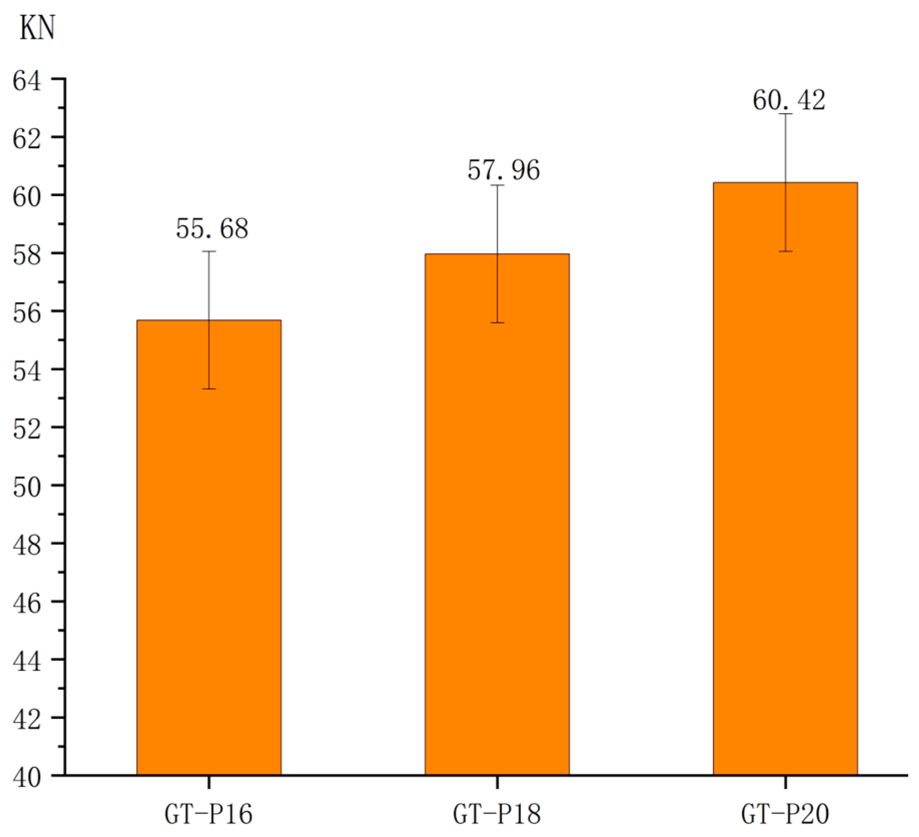
3.2.1. Ultimate Load-Bearing Capacity of the Trusses

During the failure phase (T3), tooth disengagement failure occurred at the support nodes of each truss. Due to variations in the truss performance and wood material properties, the maximum load-bearing capacities of the individual trusses were different (Figure 8).
As shown in Figure 8, the ultimate load-bearing capacities of the trusses are in the order of GT-P20 > GT-P18 > GT-P16. This indicates that the trusses connected with 20 mm wooden pins have the highest load-bearing capacity. Therefore, it can be concluded that 20 mm wooden pins are more suitable for connections between the members of triangular wooden trusses.

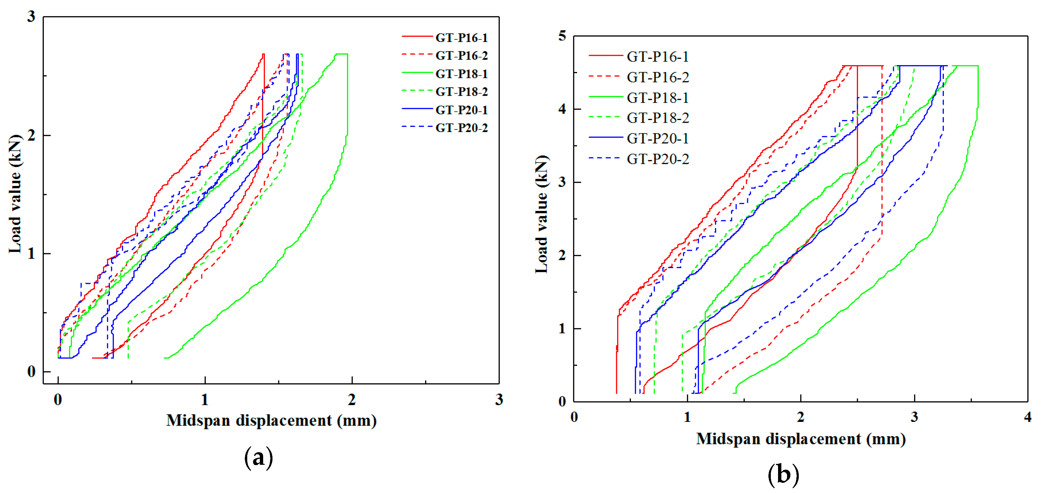
3.2.2. Stiffness of the Trusses

In Figure 9, it can be observed that the load–displacement curves for the nodes of each test specimen during the failure phase (T3) are generally similar. Initially, while loading a certain portion, the deflection at the nodes of each truss exhibited a linear relationship with the load. However, upon exceeding a specific point on the curve, the deflection began to display a nonlinear relationship with the load. The initial stiffness of each truss node during the failure phase (T3) was calculated using Pickpoint software v.3.24 (see Table 4).
Table 4 shows that during the failure phase (T3), the stiffness of the wooden pins connecting multiple trusses is in the order of GT-P16 > GT-P18 > GT-P20. In the wooden pin-connected truss system, the stiffness of GT-P18 decreased the most significantly, while GT-P16 and GT-P20 exhibited relatively smaller reductions, indicating that GT-P16 and GT-P20 have good coordination.
From the perspective of ultimate load-bearing capacity, it can be concluded that within the multiple wooden trusses connected by different wooden pins, stiffness is inversely proportional to ultimate load-bearing capacity and inversely proportional to the diameter of the wooden pins.

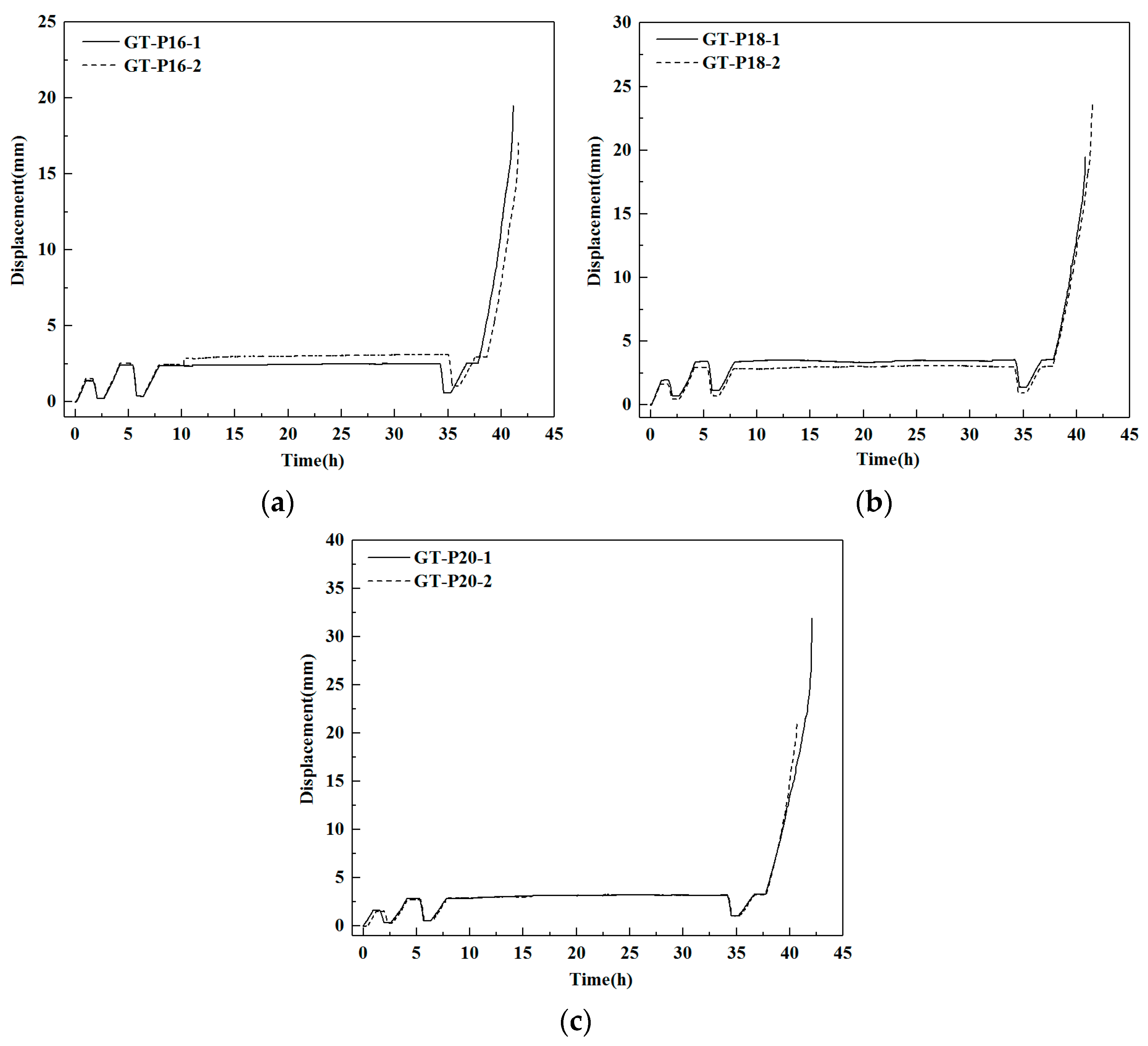
3.2.3. Truss Stability

This experiment measured the deflection at each node of every truss and produced the midspan deflection diagrams for each truss throughout the entire testing process (see Figure 10). From Figure 10, it can be observed that all three connection types of the trusses exhibited a normal testing status and demonstrated good consistency during both the T1 (0–2.5 h) and T2 (2.5–35 h) phases. However, the variability in the wood resulted in different outcomes for the various trusses during the T3 phase.
The degree of dispersion of the curves is in the order of GT-P18 > GT-P16 > GT-P20, indicating that the 20 mm pin-connected truss has the lowest curve dispersion, suggesting that this truss exhibits the highest performance stability.

3.2.4. Residual Deformation of the Truss

During the preloading phase (T1), the applied load of 0.6Pk was relatively small; the residual deformations are shown in Table 5.
From Table 5, it can be seen that during the preloading phase (T1), GT-P16 exhibited the smallest residual deformation, with the maximum residual deformation occurring at ridge node A. Among the double-span wooden trusses connected with the wooden pins of three different diameters, the residual deformations of the trusses connected with 16 mm and 20 mm wooden pins were both minimal, indicating optimal resistance to deformation.
During the standard loading phase (T2), the load was held for 60 min, followed by unloading and letting the trusses remain unloaded for 30 min. The residual deformations of the deflections at each node of the trusses are shown in Table 6.
From Table 6, it can be observed that after the first part of the standard load loading phase (T2), the residual deformations of the GT-P16 and GT-P20 trusses were quite similar and relatively small, with the GT-P16 truss showing the smallest residual deformation. Compared to the residual deformation values produced during the preloading phase (T1), the GT-P16 truss increased by 0.09 to 0.82 mm, the GT-P18 truss increased by 0.07 to 0.92 mm, and the GT-P20 truss increased by 0.04 to 0.32 mm. This indicates that the increase in the holding load has a significant impact on the residual deformation of the wooden trusses.
After the completion of the second part of the standard load loading phase, where the load was held for 24 h, the trusses were unloaded and left under empty load for 30 min. The residual deformations of each node of the trusses are shown in Table 7.
From Table 7, it can be seen that the average residual deformation at each node of the GT-P16 truss is 0.96 mm, the average residual deformation for the GT-P18 truss is 1.17 mm, and the average residual deformation for the GT-P20 truss is 0.93 mm. The GT-P16 and GT-P20 trusses exhibit the smallest residual deformations, with both having their maximum residual deformation at loading point B, measuring 1.31 mm and 1.23 mm, respectively. This indicates that the creep resistance of the double-span wooden trusses connected with the 16 mm wooden pins and with the 20 mm wooden pins are both optimal. The maximum residual deformation for all trusses occurs at loading point B, which may be due to uneven force transmission from the pulley system, resulting in a relatively larger load at point B. From the standard loading phase (T2), it is evident that the double-span wooden trusses connected with the 16 mm and 20 mm wooden pins have significantly lower residual deformations, demonstrating the best creep resistance performance.

3.2.5. Energy Dissipation Performance of the Trusses

The load–displacement diagrams of the trusses at each stage (Figure 11) allow us to calculate the area under the curves (Table 8). The area enclosed by the curves represents the energy dissipation performance of the trusses.
From Table 8, it is indicated that the enclosed area under the load–displacement curve for the GT-P16 truss is the largest, suggesting that the energy dissipation performance of the triangular multi-span wooden truss connected with 16 mm wooden pins is the best.

4. Conclusions

Static load tests were conducted on triangular wooden trusses connected with wooden pins of different diameters. By analyzing the experimental phenomena of various types of trusses during the failure phase (T3) as well as the preload phase (T1), standard load loading phase (T2), and destructive loading phase (T3), the following conclusions can be drawn:
(1)
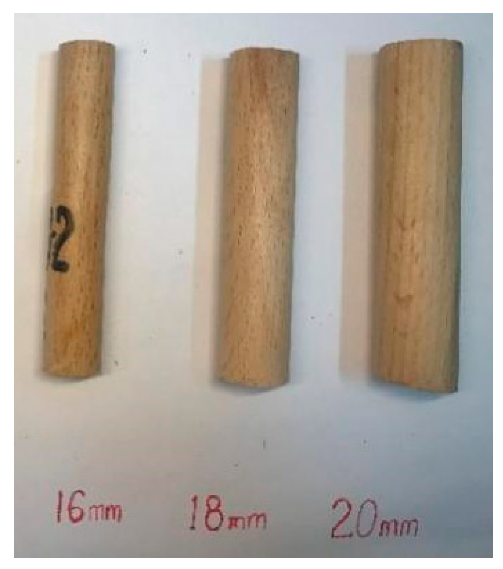
According to the failure results, the wooden pins showed no significant cracking or deformation when damage occurred. This indicates that the pins remained within the elastic range, demonstrating good coordination in the connections of the multiple wooden trusses.
(2)
In terms of the overall ultimate load-bearing capacity metrics, the truss connected with 20 mm wooden pins exhibited the best load-bearing capacity.
(3)
The stiffness of the wooden trusses connected with wooden pins is in the order of GT-P16 > GT-P18 > GT-P20. The stiffness during the second part of the standard load loading phase (T2) was significantly greater than that during the failure phase (T3), indicating that prolonged loading has a certain impact on the stiffness of wooden trusses.
(4)
The stability of the truss connected with the 20 mm wooden pins is the best.
(5)
From the perspective of deformation capacity, the double-span wooden trusses connected with the 16 mm and 20 mm wooden pins demonstrated the best resistance to deformation.
(6)
The energy dissipation performance is optimal for the truss connected with the 16 mm diameter wooden pins.
The above experimental conclusions also confirm that wooden pin connections are an effective method; they not only enhance the load-bearing capacity of multi-span wooden trusses but also improve their resistance to deformation. This connection technique utilizes wooden pins at the midpoint between sections of the upper and lower chords of the multi-span wooden truss, achieving a significant synergistic effect that effectively addresses the instability issues of single-span wooden trusses. These research findings indicate that wooden pin-connected multi-span wooden trusses have broad application prospects in modern wooden structural buildings, particularly in situations where enhanced load-bearing capacity and stability are required. This connection method allows for the efficient utilization of wood resources while improving the overall performance of wooden structures [28].

Author Contributions

Conceptualization, Y.Y.; Methodology, Y.Y.; Software, S.W.; Formal analysis, Y.Y.; Investigation, P.M., F.W. and Z.W.; Data curation, Y.Y., S.W., F.W. and Z.W.; Writing—original draft, Y.Y.; Writing—review and editing, C.C.; Supervision, Z.Q.; Project administration, Z.Q.; Funding acquisition, Z.Q. All authors have read and agreed to the published version of the manuscript.

Funding

This research received no external funding.

Data Availability Statement

The original contributions presented in the study are included in the article, further inquiries can be directed to the corresponding author.

Acknowledgments

This work was supported by the Key Think Tank Project of Jiangsu Province (No. 2024-187). The authors would like to express their sincere thanks for this support.

Conflicts of Interest

The authors declare that they have no known competing financial interests or personal relationships that could have appeared to influence the work reported in this paper.

References

  1. Lin, S.; Shi, Y. Current status and prospects of prefabricated wooden structures. J. Constr. Sci. Technol. 2019, 1, 46–51. [Google Scholar] [CrossRef]
  2. Liu, W.; Yang, H. Advances in Modern Wooden Structure Research. J. Build. Struct. 2019, 40, 16–43. [Google Scholar] [CrossRef]
  3. Madsen, B. Structural Behavior of Timber. 1992. Available online: https://api.semanticscholar.org/CorpusID:136802265 (accessed on 24 April 2013).
  4. Shi, C. Experimental and Numerical Simulation of the Load-Bearing Capacity of Tooth Plate Connected Lightweight Wooden Trusses. Master’s Thesis, Chongqing University, Chongqing, China, 2011. Available online: https://d.wanfangdata.com.cn/thesis/D282339 (accessed on 24 April 2013).
  5. Liu, Y.; Fu, M.; Liu, S.; Ge, S.; Liu, Y.; Li, N. Modern Wooden Bridges and Their Structural Forms. J. Archit. Sci. Eng. 2013, 30, 83–91. [Google Scholar] [CrossRef]
  6. Zhang, J.; Zhong, Y.; Zhao, R.; Zhou, H. Research Progress on the Mechanical Properties of Bolt Connections in Wooden Structures. J. Wood Ind. 2012, 26, 39–42+52. [Google Scholar] [CrossRef]
  7. Yang, L.; Que, Z. Establishment of Cooperation between Royal Suzhou and Nanjing Forestry University: Research on the Performance of Wood Material in High Temperature, High Humidity, and High Salt Environments. J. Int. Wood Ind. 2013, 8–9. Available online: https://www.cnki.net (accessed on 25 July 2015).
  8. Que, Z.; Li, Z.; Wang, F.; Wang, Y.; Wang, Y. The Influence of High Salinity Environments on the Shear Performance of Nail-Connected Wooden Structures. J. Ind. Build. 2015, 45, 81–85. [Google Scholar] [CrossRef]
  9. He, S.; Shang, P.; Yang, B.; Tao, J.; Wei, Y.; Zhu, Y. Shear Performance of Bamboo Nails and Steel Nails Under Corrosion-Induced Treatment. J. For. Sci. Technol. Dev. 2015, 29, 90–94. [Google Scholar] [CrossRef]
  10. JGJ/T 265-2012; Technical Specification for Lightweight Wooden Trusses. China Architecture & Building Industry Press: Beijing, China, 2012.
  11. Gupta, R.; Vatovec, M.; Miller, T.H. Metal-Plate-Connected Wood Joints: A Literature Review; Forest Research Laboratory Oregon State University: Corvallis, OR, USA, 1996; Available online: https://wur.on.worldcat.org/oclc/34647918 (accessed on 1 January 1996).
  12. Barron, K.C.; Kim, J.B. Non-linear modeling of the heel joint of metal plate connected roof trusses. In Proceedings of the World Conference on Timber Engineering, Whistler Resort, BC, Canada, 31 July–3 August 2000; Volume 7. [Google Scholar]
  13. Lau, P.W.C. Factors affecting the behaviour and modelling of toothed metal-plate joints. Can. J. Civ. Eng. 1987, 14, 183–195. [Google Scholar] [CrossRef]
  14. O’Regan, P.J.; Woeste, F.E.; Lewis, S.L. Design procedure for the steel net-section of tension splice joints in MPC wood trusses. For. Prod. J. 1998, 48, 35–42. [Google Scholar]
  15. Colonias, K.W. Multiple Wood Truss Connection. U.S. Patent 4,890,436, 1 February 1990. [Google Scholar]
  16. Bugbee, M.W.; Colonias, K.W. Light Wood Truss Connection. U.S. Patent 5,042,217, 27 August 1991. [Google Scholar]
  17. Sejkot, P.; Ormarsson, S.; Vessby, J.; Källsner, B. Numerical out-of-plane stability analysis of long span timber trusses with focus on buckling length calculations. Eng. Struct. 2020, 204, 109670. [Google Scholar] [CrossRef]
  18. Xu, X. Research on the Load-Bearing Capacity of Lightweight Wooden Trusses. Master’s Thesis, Tongji University, Shanghai, China, 2006. Available online: https://doi.org/10.7666/d.y846616 (accessed on 15 June 2006).
  19. Kuang, Y. Experimental Study on the Stress Performance of Tooth Plate Connection Joints in Lightweight Wooden Trusses. Master’s Thesis, Chongqing University, Chongqing, China, 2011. Available online: https://d.wanfangdata.com.cn/thesis/D282934 (accessed on 15 January 2012).
  20. Huang, H.; He, M. Experimental Research on the Structural Performance of Lightweight Wooden Truss Systems. J. Jiamusi Univ. (Nat. Sci. Ed.) 2009, 27, 481–485+492. [Google Scholar] [CrossRef]
  21. Che, Y. Research on Testing Methods and Loading Procedures for Metal Tooth Plate Connected Lightweight Wooden Trusses. Master’s Thesis, Chongqing University, Chongqing, China, 2013. Available online: https://doi.org/10.7666/d.D353874 (accessed on 31 October 2013).
  22. Gao, Y. Design and Optimization of Connection Joints in Multiple Wooden Trusses. Master’s Thesis, Nanjing Forestry University, Nanjing, China, 2017. [Google Scholar]
  23. Chen, Q.; Teng, Q.; Gao, Y.; Zeli, Q. The Impact of Member Arrangement on the Load-Bearing Capacity of Parallel Chord Wooden Trusses. J. Wood Ind. 2017, 31, 20–25. [Google Scholar] [CrossRef]
  24. Que, Z.; Gao, Y.; Ge, S. Research status and development trend of multiple wooden trusses. J. For. Eng. 2017, 2, 138–144. [Google Scholar] [CrossRef]
  25. GB/T 50329-2012; Standard Test Methods for Timber Structures. The Ministry of Construction of the People’s Republic of China Press: Beijing, China, 2012.
  26. Chang, C.; Que, Z.; Liu, Y.; Hou, T.; Chen, L.; Wang, X.; Yao, Z. A Truss Loading Device. P. Jiangsu Province CN. 201810405679, 24 November 2023. [Google Scholar]
  27. GB5009−2012; Code for the Design Loading of Building Structures. China Architecture & Building Industry Press: Beijing, China, 2012.
  28. Wang, F.; Teng, Q.; Gao, Y.; Chen, Q.; Wang, C.; Zeli, Q. Static load test and bearing capacity of multiple wooden trusses. J. Civil Environ. Eng. 2019, 41, 86–92. [Google Scholar] [CrossRef]
Figure 1. (a) Design drawing of truss dimensions; (b) Wooden pin diagram.
Forests 15 01675 g001
Figure 2. (a) Node location; (b) processing of joints.
Forests 15 01675 g002
Figure 3. Design and practical drawing of loading device: 1—fixed pulley; 2—rope; 3—pulley group; 4—support device.
Forests 15 01675 g003
Figure 4. Anti-overturning device.
Forests 15 01675 g004
Figure 5. Continuous loading system.
Forests 15 01675 g005
Figure 6. Tooth plate shedding failure of support node. (a) Test samples, GT-P16-1 truss. (b) Test samples, GT-P16-2 truss. (c) Test samples, GT-P18-1 truss. (d) Test samples, GT-P18-2 truss. (e) Test samples, GT-P20-1 truss. (f) Test samples, GT-P20-2 truss.
Forests 15 01675 g006
Figure 7. Wooden pins after testing.
Forests 15 01675 g007
Figure 8. Ultimate load-bearing capacities of various trusses.
Forests 15 01675 g008
Figure 9. The load–displacement curves of truss joints connected by wooden pins of different diameters at the failure stage (T3). (a) 16 mm diameter. (b) 18 mm diameter. (c) 20 mm diameter.
Forests 15 01675 g009
Figure 10. Bending variation in the midspan of the truss lower chord when connected by wooden pins of different diameters. (a) 16 mm diameter. (b) 18 mm diameter. (c) 20 mm diameter.
Forests 15 01675 g010
Figure 11. Load–displacement curves for midspan of truss. (a) T1 phase. (b) T2 phase.
Forests 15 01675 g011
Table 1. Material parameters of specimen (unit: MPa).
Modulus of ElasticityFlexural StrengthCompressive Strength Along GrainTensile Strength Along GrainTransverse Compressive Strength
12220.9 ± 6.21 *85.32 ± 1.18 *45.15 ± 4.3 *10.21 ± 1.25 *7.6 ± 1.8 *
Note: The value of * is standard deviation.
Table 2. Performance parameters of metal plate.
Tooth Plate Thickness(mm)Density of Plate Teeth (Each/mm2)Length of Plate Teeth (mm)Elastic Modulus of Steel (GPa)Tensile Yield Strength of Steel (MPa)
0.900.0128.6203248
Note: The data are provided by the generating manufacturer.
Table 3. Number and identifier of trusses.
Number of TrussesDouble Truss
The diameter of the wooden pins at the connection between wooden trusses.Wooden pin with diameter of 16 mmWooden pin with diameter of 18 mmWooden pin with diameter of 20 mm
Number222
Identifier of trussGT-P16-1
GT-P16-2
GT-P18-1
GT-P18-2
GT-P20-1
GT-P20-2
Note: GT is multi-beam truss, and P is wood pin connection.
Table 4. Initial stiffness of each truss node during the failure phase (T3) (unit: kN/mm).
Identifier of TrussNode A Node B Node C Midspan K NodeNode E Node F AverageStandard Deviation
GT-P161.822.091.831.481.741.781.640.196
GT-P181.251.151.511.211.451.601.430.183
GT-P201.421.441.441.191.351.571.340.126
Note: The stiffness calculation is derived from Pickpoint software.
Table 5. Residual deformations of each truss after preloading (mm).
Identifier of TrussMidspanNode ANode BNode CNode ENode F
GT-P16 0.240.530.510.310.150.21
GT-P18 0.590.690.710.560.560.56
GT-P20 0.330.290.690.380.340.15
Table 6. Residual deformations of each truss after 60 minutes of standard load (mm).
Identifier of TrussMidspanNode ANode BNode CNode ENode F
GT-P160.370.830.750.530.30.34
GT-P180.931.041.290.830.760.87
GT-P200.560.590.990.540.540.3
Table 7. Residual deformations of each truss after 24 hours of standard load holding (mm).
Identifier of TrussMidspanNode ANode BNode ENode FAverageStandard Deviation
GT-P16 0.821.291.310.660.700.9560.286
GT-P180.971.311.541.121.041.1960.215
GT-P20 1.051.021.230.850.550.940.233
Table 8. Enclosed areas of the load–displacement curves of truss joints.
Identifier of TrussNode ANode BNode CMidspanNode ENode FAverage
GT-P163.774.373.605.212.913.303.86
GT-P184.313.813.534.063.082.793.60
GT-P202.013.062.514.702.532.342.86
Disclaimer/Publisher’s Note: The statements, opinions and data contained in all publications are solely those of the individual author(s) and contributor(s) and not of MDPI and/or the editor(s). MDPI and/or the editor(s) disclaim responsibility for any injury to people or property resulting from any ideas, methods, instructions or products referred to in the content.

