
Tunable Spun Fiber Constructs in Biomedicine: Influence of Processing Parameters in the Fibers’ Architecture

 , and
, and 
Abstract
:1. Introduction
2. Electrospinning
2.1. Principle and Setup
2.2. Categories
2.3. Fiber Structural Organization
2.3.1. Core-Shell

2.3.2. Tri-Axial
2.3.3. Hollow
2.3.4. Porous
2.3.5. Side-by-Side
2.3.6. Multilayered
2.4. Tissue Engineering and Drug Delivery Applications

| Active Agents | |||||||
|---|---|---|---|---|---|---|---|
| Polymers | Name | Characteristics | Structural Organization | Solution and Processing Parameters | Major Findings | Envisaged Applications | Ref. |
| PU; HA/St | HA | Group of polysaccharide molecules, usually found on connective tissues | Core-shell | Core: PU (12% w/v) was dissolved in DMF; the solution was injected at 675 mL/min through a co-axial needle with inner diameter of 1.6 mm; Shell: both St (9% w/v) and HA (1% w/v) were dissolved in water; the solution was injected at a feed rate < 0.135 mL/min through a co-axial needle with outer diameter of 2.0 mm. | A uniform structure was obtained; modification with HA enhanced cell adhesion into fibrous scaffolds | Skin scaffolding systems; wound healing | [118] |
| PCL; PEG | Ag NPs; ZnO NPs | AgNPs display unique optical, electrical, thermal, and biological properties, being used for several antimicrobial and medical-coating applications; ZnO is an essential ingredient for several enzymes, being used for pain relieve and as an antimicrobial agent. | Core-shell | Core: Ag NP (0.01/0.02% w/v) were diluted in water and the solution was injected at 0.0067 mL/min; Shell: PCL (14% w/v), PEG (7% w/v) and ZnO NP (1.6% w/v) suspensions were prepared separately in CHF/DMF (17:10); the shell solution was injected at 0.0167 mL/min; Voltages of 16/20/21 kV were applied; the spinneret-collector distance was kept at 20 cm and the co-axial spinneret presented a 0.90 mm inner diameter and 1.60 mm outer diameter. | Ag NPs showed a fine-tuned release rate through pores formed along the shell structure; fibers presented excellent mechanical stability | Drug delivery systems | [27] |
| PLA; PCL | TCH | Bacteriostatic agent that inhibits protein synthesis; effective antibacterial agent. | Core-shell | Core: PCL (10% w/v) dissolved in CHF; Shell: PLA (10% w/v) in CHF; TCH (5% w/v) was dissolved in methanol and then added to the PLA solution (CHF:methanol ratio of 19:1); Voltages of 12.5–17.0 kV were applied and a needle with a 2.5 mm outer diameter was used. | The composition of the shell influenced the initial burst release, by working as a diffusion barrier | Drug delivery systems | [13] |
| PCL; PGS | Heparin | Polyanionic polysaccharide; works as an anticoagulant. | Core-shell | Core: PGS (0/40/60/80% w/v) was dissolved in TFE; the solution was injected at 0.030 mL/min; Shell: PCL (13% w/v) was dissolved in TFE; the solution was injected at 0.180 mL/min; A voltage of 15 kV was applied; the spinneret-collector distance was of 15 cm and the needle presented an inner diameter of 0.94 mm and outer diameter of 2.50 mm. | Slow degradation of PCL provided the fibers with structural integrity, whereas fast degradation of PGS increased their elasticity; addition of PGS and grafting of heparin enhanced the attachment and proliferation of human umbilical vein endothelial cells | Tissue engineering scaffolds | [119] |
| PCL | ShHL | Derived from Halomonas levan; is a bacterial-origin linear polymer that possesses anti-oxidant and anti-cancer activities. | Core-shell | Core: PCL (10% w/v) was dissolved in THF and DMF (1:1); the solution was injected through a needle with an inner diameter of 1.3 mm; Shell: ShHL (7% w/v) was dissolved in water; The solution was injected through a needle with an outer diameter of 2.7 mm. | The increase of ShHL content led to higher ultimate tensile strengths; fibers showed high potential in decreasing neointimal proliferation and thrombogenicity of grafts and prosthesis | Tissue engineering scaffolds; blood-contacting devices | [120] |
| PCL; PLGA; GN | RhB; FITC | FITC is a derivative of fluorescein, used for flow cytometry detection. | Tri-axial | Core: PCL 1% w/v dissolved in HFP, injected at 0.00833 mL/min; Intermediate layer: GN 2% w/v dissolved in HFP, injected at 0.00833 mL/min; Shell: PLGA 25% w/v dissolved in HFP, injected at 0.0125 mL/min; 0.25% w/v RhB and 1% w/v FITC were used as active agents; A 0.75–1.5 kV voltage was applied, using a collector distance of 10–25 cm. | The addition of PCL increased the fibers elastic modulus; fibers showed ideal support for the growth of mesenchymal stem cells | Regenerative engineering and drug delivery systems | [121] |
| CA; PVP | KET | Nonsteroidal anti-inflammatory drug, used to treat pain and/or inflammation cause by arthritis. | Tri-axial | Core: CA/KET, injected at 0.0167 mL/min; Intermediate layer: bank CA layer, injected at 0.00833 mL/min; Shell: PVP/KET, injected at 0.0167 mL/min; A voltage of 17 kV was applied, with a collector distance of 20 cm. | Fibers presented good dual drug release, with more accurate release contents at the initial stage and more prolonged sustained release at the second stage | Drug delivery systems | [122] |
| PLA; PCL | DOX | Chemotherapy medication. | Porous | PLA and PCL were dissolved in DCM/DMF (98:2) in ratios of 3/1, 1/1 and 1/3, with a total polymer concentration of 8% w/v; CuS NPs were synthesized in a mixture of CuCl2·2H2O, sodium citrate and Na2S and then added to the PLA/PCL mixture; the solution was injected at 0.0333 mL/min using a voltage of 15 kV. | Fiber membranes promoted cutaneous wound healing, along with enhanced mechanical support and controlled release of therapeutic copper ions | Drug delivery systems; wound healing | [123] |
| PCL | CAM | Antibiotic used to treat eye infections. | Porous | CAM (4% w/v) was added to the electrospinning solution after PCL (12.5/15% w/v) was dissolved in mixtures of acetone, CHF, DCM, DMSO, THF, acetic acid and formic acid; a blunt metal needle with 0.60 mm diameter was used; the solution was injected at 0.0167 mL/min; the spinneret-collector distance was kept at 15 cm and voltages of 11, 13 and 15 kV were applied. | Drug release from porous microfibers was facilitated; changes in humidity allows for fiber structure to be tuned and, consequently, the drug release profile | Drug delivery systems | [124] |
| PLLA | - | - | Porous | PLLA (8% w/v) was dissolved in CHF at room temperature; SLES (25% w/v) was then added to the PLLA solution; the solution was injected at 0.0083 mL/min; a metal needle of 0.7 mm diameter was used; 6 kV were applied, and the distance of the spinneret-collector was of 2.0 cm. | 3D mats were formed with porous fibers and the addition of SLES surfactant led to higher crystallinity degree and enhanced cell proliferation | Tissue engineering scaffolds | [125] |
| SF; PLLA | - | - | Side-by-side | Side 1: SF (10% w/v) was dissolved in HFIP; Side 2: PLLA (4% w/v) was dissolved in HFIP; Each solution was injected at 0.0055 mL/min; 15 kV voltage was applied, and the spinneret-collector distance was kept at 15 cm. | Results showed a dependence of the molecular orientation and secondary structure of the fibers on the alignment and annealing conditions; fibers treated with methanol and heated at 80 ºC revealed enhanced mechanical features | Medicine regenerative scaffolds; drug delivery systems | [126] |
| PVP; PAN | DXM; 1,8-naphthalene anhydride; PMI | DXM is a corticosteroid, similar to natural hormones produced by adrenal glands; PMI is an anhydride diester, that can also be used as an intermediate for the synthesis of perylene carboxylic derivatives. | Side-by-side | Side 1: PVP (15% w/v) was dissolved in DMF; DXM and 1,8-naphthalene anhydride were added to the PVP solution; Side 2: PAN (8% w/v) was dissolved in DMF; DXM and PMI were added to the PAN solution Voltages of 17–20 kV were applied; each solution was injected at 0.00835 mL/min; the spinneret-collector distance was of 15 cm. | Self-supporting properties were exhibited when PVP was dissolved in water; ideal biphasic drug release profiles were attained | Biphasic drug release | [127] |
| PVP; EC | KET | Nonsteroidal anti-inflammatory drug, used to treat pain and/or inflammation cause by arthritis. | Side-by-side | Side 1: PVP (8% w(v) and KET (2% w/v) were both dissolved in ethanol; Side 2: EC (24% w/v) and KET (2% w/v) were both dissolved in ethanol; A voltage of 12 kV was applied; a spinneret-collector distance of 20 cm was used, and solutions were injected at 0.0167 mL/min. | PVP dissolved very rapidly and delivered a loading dose of ketoprofen, whereas EC released ketoprofen in a more sustained way; when PVP was added to EC, the second stage of release was accelerated | Drug delivery systems | [128] |
| Alginate; PCL; PEO | ZnO NPs; Triton X-100 | Triton X-100 is a common nonionic surfactant, with conductive and dissipative properties. | Multilayered | Layer 1: PCL (10/20/30% w/v) was dissolved in GAA/Ac (1/1 and 3/1); a spinneret-collector distance of 20 cm was applied; 15 kV voltage were applied, using a 0.4 mm diameter needle; the solution was injected at 0.0167 mL/min Layer 2: SA (1% w/v) was dissolved in a water suspension containing 0.25% w/v ZnO NPs; PEO powder and Triton X-100 were added; a spinneret-collector distance of 15 cm was applied; 12.5 kV voltage were applied, using a 0.4 mm diameter needle; the solution was injected at 0.0125 mL/min | PCL provided good mechanical properties to the membrane, and worked as a protection from the external environment; alginate internal layer promoted cell viability, removed exudates, and allowed gas exchanges; ZnO NPs was antibacterial and bacteriostatic | Skin wound patch | [129] |
| PCL; PLGA | RhB | RhB is an organic compound and a dye, used within water to determine direction flow. | Multilayered | Layer 1: PCL (10% w/v) was dissolved in DCM-DMF (80:20); the solution was injected at 0.0334 mL/min; 20 kV of voltage were applied; a 1 mm diameter needle was used; a spinneret-collector distance of 10 cm was used Layer 2: PLGA (24% w/v) was dissolved in DMF; RhB (5% w/v) was added to PLGA solution in a ratio of 65:35; the solution was injected at 0.0501 mL/min; 20 kV of voltage were applied; a 1 mm diameter needle was used; a spinneret-collector distance of 10 cm was employed Layer 3: similar to Layer 1 | A prolonged release was achieved; FE and computational models could both provide accurate predictions of drug release | Prolonged drug delivery systems | [130] |
| PLLA | - | - | Multilayered | Layer 1: PLLA (7.5% w/v) was dissolved in HFIP; the solution was injected at 0.0167 mL/min; a 0.8 mm diameter needle was used; 12 kV voltage were applied and a spinneret-collector distance of 15 cm was kept Layers 2 and 3: similar to Layer 1 | Multilayer structures presented higher tensile strengths and favored the colonization and migration of H9C2 cells | Tissue regeneration scaffolding systems | [131] |
| PCL; mGLT | - | - | Multilayered | Layer 1: PCL particles were dissolved in 18% w/v TFE; a voltage of 8 kV was applied Layer 2: mGLT (20% w/v) was dissolved in 95% w/v TFE; 15 kV voltage were applied Both layers were alternated, and in each layer a 22 G needle was used, with a spinneret-collector distance of 15 cm; both solutions were injected at 0.0334 mL/min | mGLT uniform distribution was attained and the scaffold maintained its mechanical strength; photocrosslinking allowed to form multilayered constructs, mimicking the structure of native tendon tissues | Tissue and ligament regeneration | [132] |
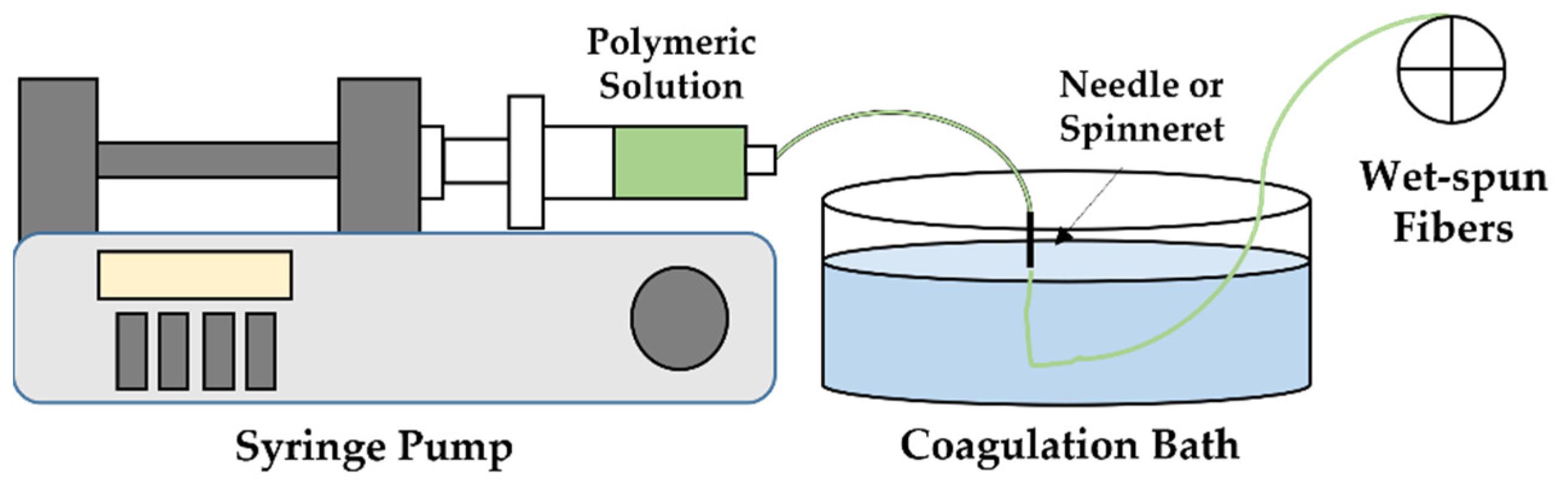
3. Wet-Spinning
3.1. Principle and Setup
3.2. Fiber Structural Organization
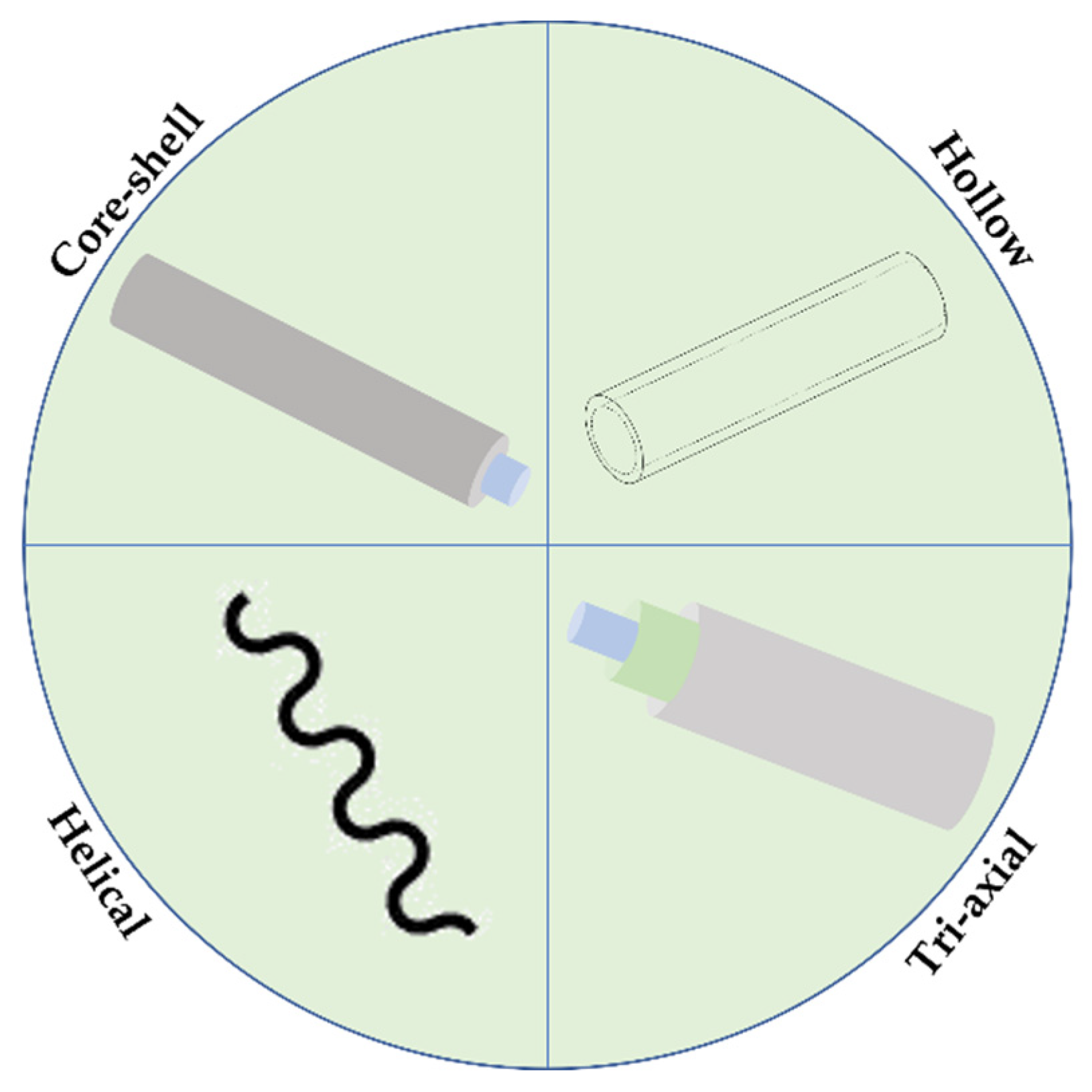

3.2.1. Helical
3.2.2. Core-Shell
3.2.3. Tri-Axial
3.2.4. Hollow
3.3. Tissue Engineering and Drug Delivery Applications
| Active Agents | |||||||
|---|---|---|---|---|---|---|---|
| Polymers | Name | Characteristics | Structural Organization | Solution and Processing Parameters | Major Findings | Envisaged Applications | Ref. |
| PLA; PLGA; Alg | Mouse myoblasts | Cells that originate mouse muscle cells | Monolayer (uniaxial) | Alg (2/4% w/v) was dissolved in deionized water; cells were suspended in HEPES (20/40/60 million cells/mL) and mixed with Alg solution; the solution was extruded at 0.03 mL/min within a 2% w/v CaCl2 coagulation bath; 20% w/v 75:25 PLA:PLGA solution dissolved in CHF was injected at 0.0301 mL/min in a coagulation bath of isopropanol; fibers were then seeded with myoblasts; a 0.31 mm diameter needle was used. | Improved in vitro proliferation; exceptional migration of cells; superior engraftment of donor cells | Regenerative skeletal muscle tissue constructs | [164] |
| CA; PCL | Cinnamon leaf oil, Clove oil and Cajeput oil | Essential oils derived from steam distillation of plant leaves | Monolayer (uniaxial) | CA (10% w/v) and PCL (14% w/v) solutions were dissolved in acetic acid, separately; the solutions were injected at 0.00835 mL/min into a coagulation bath of ethanol. | Essential oil-loaded fibers eliminated bacteria more quickly than conventional antibiotics, proving their effective potential to replace antibiotics | Drug delivery systems (i.e., essential oils) | [134] |
| SA/FK | IDM | Non-steroid anti-inflammatory used to relieve pain, swelling and joint stiffness caused by arthritis | Monolayer (uniaxial) | FK (0.4/0.5/0.67% w/v) was dissolved in 0.5% w/v NaOH; IDM (1% w/v) and SA (2% w/v) were added to the solution; a 3% w/v CaCl2 coagulation bath was used. | IDM release profile increases over time, relieving the gastrointestinal system from side effects | Drug delivery system to relieve the gastrointestinal side reaction of indomethacin | [165] |
| SA; GN | Nisin Z | Antimicrobial peptide, originated by the substitution of asparagine for histidine from Nisin A | Monolayer (uniaxial) | SA 2% w/v was dissolved in deionized water, with posterior addition of a GN 1% w/v solution, previously dissolved in water, in a ratio of 70:30, respectively; A 1.024 mm diameter needle was used, maintaining a collector distance of 3 cm, with a coagulation bath of 2% w/v CaCl2 solution; the spinning solution was injected at 0.1 mL/min; Fibers were then immersed in Nisin Z. | The incorporation of the peptide improved the fibers structural integrity and provided antibacterial effects against S. aureus | Tissue engineering | [163] |
| CHI | IONPs | IONPs display superparamagnetic properties, usually being presented as magnetite or in its oxidized maghemite form | Helical | IONPs (10% w/v) were suspended in 1% w/v acetic acid; CHI (30% w/v) was used as additive; the solution was injected at 0.334 mL/min into a coagulation bath of absolute ethanol; a 0.25 mm diameter needle was employed. | IONPs were distributed in the fiber matrix as large clusters; dried CHI helices presented spring-like elastic behavior; fibers had strong ferromagnetic properties and exhibited a Young’s modulus in the range of wet-spun CHI fibers | Magnetic and motion-activated cell scaffolds | [21] |
| CHI-PSS; CHI-PAA/PVS | - | - | Core-shell | Core: CHI (1.5/1.0% w/v) was dissolved in 1% w/v acetic acid; the solution was pumped at 1.0 mL/min and 0.5 mL/min, respectively; Shell: PSS (10% w/v)/PVS (30% w/v) were dissolved in deionized water; solutions were injected at 0.4 mL/min and 0.5 mL/min, respectively; A coagulation bath of 50/50 v/v water/ethanol was used and the distance between the nozzle and the coagulation bath was kept at 3 cm. | Fibers mechanical properties were improved by doping PSS with PEO; fibers presented excellent elongation at break | Tissue engineering scaffolds | [166] |
| PSU | - | - | Core-shell | Core: egg albumen was separated from the eggs and extruded at 0.367 mL/min; Shell: PSU (18% w/v) was dissolved in DMF and extruded at 0.585 mL/min; A distilled water coagulation bath was used; the inner diameter of the needle was 0.7 mm with a gap between both layers of 0.25 mm. | A dense structure was obtained in the hollow space of the PSU fiber; the albumen fiber presented good gloss and mechanical properties | Tissue engineering scaffolds | [167] |
| CHI; Alg | - | - | Core-shell | Core: CHI (0.5/1.0/2.0% w/v) with different amounts of 2% w/v CaCl2; the solution was injected at 0.234 mL/min; Shell: SA (<2% w/v) was prepared in water; the solution was extruded at 0.418 mL/min; A coagulation bath of 2% w/v CaCl2 was used. | The incorporation of CaCl2 at the fiber’s core enhanced the mechanical properties by 260%; cylinder-shaped monofilaments of chitosan coated with alginate were successfully observed | Drug delivery systems | [135] |
| HA; SH | IONPs; octenidine dihydrochloride | Octenidine dihydrochloride is a cationic surfactant, active against bacteria | Core-shell | Core: SH was dissolved in water; Shell: HA was prepared with IONPs or octenidine dihydrochloride. | Drug release from the core occurred through cracks; this rupture effect has can be used as a trigger release | Drug carrier | [149] |
| PLGA; Alg | Dexamethasone; dexamethasone-21-phosphate | Corticosteroid, similar to a natural hormone produced by your adrenal glands; dexamethasone 21-phosphate works as an inducer of apoptosis and inhibitor of the sodium phosphate symporter | Core-shell | Core: PLGA (20% w/v) and dexamethasone (7% w/v) were dissolved in DMSO (73% w/v); Shell: Alg (1% w/v) was dissolved in water and a 0.1% w/v dexamethsome-21 phosphate aqueous solution was added to the Alg solution; A 0.31 mm diameter needle was used, along with a 5% w/v CaCl2 coagulation bath. | Alg shell delayed dexamethasone release; the core-shell structure presented two stage releases of dexamethasone and dexamethasone-21-phosphate, with minimum initial burst release | Dual drug delivery system | [168] |
4. Conclusions
Author Contributions
Funding
Institutional Review Board Statement
Informed Consent Statement
Data Availability Statement
Acknowledgments
Conflicts of Interest
References
- Liang, D.; Hsiao, B.S.; Chu, B. Functional electrospun nanofibrous scaffolds for biomedical applications. Adv. Drug Deliv. Rev. 2007, 59, 1392–1412. [Google Scholar] [CrossRef] [Green Version]
- Jiang, H.; Hu, Y.; Li, Y.; Zhao, P.; Zhu, K.; Chen, W. A facile technique to prepare biodegradable coaxial electrospun nanofibers for controlled release of bioactive agents. J. Control. Release 2005, 108, 237–243. [Google Scholar] [CrossRef] [PubMed]
- Miranda, C.S.; Ribeiro, A.R.M.; Homem, N.C.; Felgueiras, H.P. Spun Biotextiles in Tissue Engineering and Biomolecules Delivery Systems. Antibiotics 2020, 9, 174. [Google Scholar] [CrossRef] [PubMed]
- Cook, J.G. Woodhead Publishing in Textiles. In Handbook of Textile Fibre Structure; Woodhead Pub.: Sawston, UK, 2009; pp. 3–8. [Google Scholar] [CrossRef]
- King, M.; Gupta, B.; Guidoin, R. Biotextiles as Medical Implants; Elsevier: Amsterdam, The Netherlands, 2013; pp. 31–34. [Google Scholar] [CrossRef]
- Abbasian, M.; Massoumi, B.; Mohammad-Rezaei, R.; Samadian, H.; Jaymand, M. Scaffolding polymeric biomaterials: Are naturally occurring biological macromolecules more appropriate for tissue engineering? Int. J. Biol. Macromol. 2019, 134, 673–694. [Google Scholar] [CrossRef] [PubMed]
- Nimni, M.E.; Cheung, D.; Strates, B.; Kodama, M.; Sheikh, K. Chemically modified collagen: A natural biomaterial for tissue replacement. J. Biomed. Mater. Res. 1987, 21, 741–771. [Google Scholar] [CrossRef]
- Liang, J.; Grijpma, D.W.; Poot, A.A. Tough and biocompatible hybrid networks prepared from methacrylated poly(trimethylene carbonate) (PTMC) and methacrylated gelatin. Eur. Polym. J. 2020, 123, 109420. [Google Scholar] [CrossRef]
- Chew, S.Y.; Wen, Y.; Dzenis, Y.; Leong, K. The Role of Electrospinning in the Emerging Field of Nanomedicine. Curr. Pharm. Des. 2006, 12, 4751–4770. [Google Scholar] [CrossRef] [PubMed] [Green Version]
- Han, D.; Steckl, A.J. Triaxial Electrospun Nanofiber Membranes for Controlled Dual Release of Functional Molecules. ACS Appl. Mater. Interfaces 2013, 5, 8241–8245. [Google Scholar] [CrossRef]
- Esparza, Y.; Ullah, A.; Boluk, Y.; Wu, J. Preparation and characterization of thermally crosslinked poly(vinyl alcohol)/feather keratin nanofiber scaffolds. Mater. Des. 2017, 133, 1–9. [Google Scholar] [CrossRef]
- Angel, N.; Guo, L.; Yan, F.; Wang, H.; Kong, L. Effect of processing parameters on the electrospinning of cellulose acetate studied by response surface methodology. J. Agric. Food Res. 2019, 2, 100015. [Google Scholar] [CrossRef]
- Frantzen, M.T.; Fojan, P.; Pedersb, D. Electrospinning of Core-Shell Fibers for Drug Release Systems. J. Self-Assem. Mol. Electron. 2017, 5, 17–30. [Google Scholar] [CrossRef] [Green Version]
- Puppi, D.; Mota, C.; Gazzarri, M.; Dinucci, D.; Gloria, A.; Myrzabekova, M.; Ambrosio, L.; Chiellini, F. Additive manufacturing of wet-spun polymeric scaffolds for bone tissue engineering. Biomed. Microdevices 2012, 14, 1115–1127. [Google Scholar] [CrossRef]
- Muiznieks, L.D.; Keeley, F.W. Molecular assembly and mechanical properties of the extracellular matrix: A fibrous protein perspective. Biochim. Biophys. Acta-Mol. Basis Dis. 2013, 1832, 866–875. [Google Scholar] [CrossRef] [PubMed] [Green Version]
- Cong, H.-P.; Ren, X.; Wang, P.; Yu, S.-H. Wet-spinning assembly of continuous, neat and macroscopic graphene fibers. Sci. Rep. 2012, 2, 613. [Google Scholar] [CrossRef] [Green Version]
- Mirabedini, A.; Foroughi, J.; Wallace, G.G. Developments in conducting polymer fibres: From established spinning methods toward advanced applications. RSC Adv. 2016, 6, 44687–44716. [Google Scholar] [CrossRef] [Green Version]
- Liu, W.; Zhang, J.; Liu, H. Conductive Bicomponent Fibers Containing Polyaniline Produced via Side-by-Side Electrospinning. Polymers 2019, 11, 954. [Google Scholar] [CrossRef] [PubMed] [Green Version]
- Cai, M.; He, H.; Zhang, X.; Yan, X.; Li, J.; Chen, F.; Yuan, D.; Ning, X. Efficient Synthesis of PVDF/PI Side-by-Side Bicomponent Nanofiber Membrane with Enhanced Mechanical Strength and Good Thermal Stability. Nanomaterials 2018, 9, 39. [Google Scholar] [CrossRef] [Green Version]
- Gibson, P.; Schreuder-Gibson, H.; Rivin, D. Transport properties of porous membranes based on electrospun nanofibers. Colloids Surf. A Physicochem. Eng. Asp. 2001, 187–188, 469–481. [Google Scholar] [CrossRef]
- Brüggemann, D.; Michel, J.; Suter, N.; De Aguiar, M.G.; Maas, M. Wet-spinning of magneto-responsive helical chitosan microfibers. Beilstein J. Nanotechnol. 2020, 11, 991–999. [Google Scholar] [CrossRef]
- Elahi, F.; Lu, W. Core-shell Fibers for Biomedical Applications-A Review. J. Bioeng. Biomed. Sci. 2013, 3, 121. [Google Scholar] [CrossRef] [Green Version]
- Li, D.; Xia, Y. Electrospinning of Nanofibers: Reinventing the Wheel? Adv. Mater. 2004, 16, 1151–1170. [Google Scholar] [CrossRef]
- Mirabedini, A. Developing Novel Spinning Methods to Fabricate Continuous Multifunctionalfor Bioapplications; Springer: Basel, Switzerland, 2017; Volume 1, pp. 1–235. [Google Scholar]
- Neisiany, R.E.; Enayati, M.S.; Kazemi-Beydokhti, A.; Das, O.; Ramakrishna, S. Multilayered Bio-Based Electrospun Membranes: A Potential Porous Media for Filtration Applications. Front. Mater. 2020, 7, 67. [Google Scholar] [CrossRef]
- Raja, K.; Prabhu, C.; Subramanian, K.S.; Govindaraju, K. Electrospun polyvinyl alcohol (PVA) nanofibers as carriers for hormones (IAA and GA3) delivery in seed invigoration for enhancing germination and seedling vigor of agricultural crops (groundnut and black gram). Polym. Bull. 2021, 78, 6429–6440. [Google Scholar] [CrossRef]
- Mahdieh, Z.; Mitra, S.; Holian, A. Core–Shell Electrospun Fibers with an Improved Open Pore Structure for Size-Controlled Delivery of Nanoparticles. ACS Appl. Polym. Mater. 2020, 2, 4004–4015. [Google Scholar] [CrossRef]
- Xue, J.; Xie, J.; Liu, W.; Xia, Y. Electrospun Nanofibers: New Concepts, Materials, and Applications. Acc. Chem. Res. 2017, 50, 1976–1987. [Google Scholar] [CrossRef]
- Teixeira, M.A.; Amorim, M.T.P.; Felgueiras, H.P. PVA/CA based electrospun nanofibers: Influence of processing parameters in the fiber diameter. IOP Conf. Ser. Mater. Sci. Eng. 2019, 634, 012040. [Google Scholar] [CrossRef]
- Zelkó, R.; Lamprou, D.A.; Sebe, I. Recent Development of Electrospinning for Drug Delivery. Pharmaceutics 2019, 12, 5. [Google Scholar] [CrossRef] [Green Version]
- Felgueiras, H.P.; Tavares, T.D.; Amorim, M.T.P. Biodegradable, spun nanocomposite polymeric fibrous dressings loaded with bioactive biomolecules for an effective wound healing: A review. IOP Conf. Ser. Mater. Sci. Eng. 2019, 634, 012033. [Google Scholar] [CrossRef] [Green Version]
- Narayanan, K.B.; Park, G.T.; Han, S.S. Electrospun poly(vinyl alcohol)/reduced graphene oxide nanofibrous scaffolds for skin tissue engineering. Colloids Surf. B Biointerfaces 2020, 191, 110994. [Google Scholar] [CrossRef]
- Huang, Z.-X.; Wu, J.-W.; Wong, S.-C.; Qu, J.-P.; Srivatsan, T.S. The technique of electrospinning for manufacturing core-shell nanofibers. Mater. Manuf. Process. 2017, 33, 202–219. [Google Scholar] [CrossRef]
- Wen, P.; Zong, M.-H.; Linhardt, R.J.; Feng, K.; Wu, H. Electrospinning: A novel nano-encapsulation approach for bioactive compounds. Trends Food Sci. Technol. 2017, 70, 56–68. [Google Scholar] [CrossRef]
- Hong, J.; Yeo, M.; Yang, G.H.; Kim, G. Cell-Electrospinning and Its Application for Tissue Engineering. Int. J. Mol. Sci. 2019, 20, 6208. [Google Scholar] [CrossRef] [PubMed] [Green Version]
- Ramakrishnan, R.; Gimbun, J.; Ramakrishnan, P.; Ranganathan, B.; Reddy, S.M.M.; Shanmugam, G.; Ganesh, S. Effect of Solution Properties and Operating Parameters on Needleless Electrospinning of Poly(Ethylene Oxide) Nanofibers Loaded with Bovine Serum Albumin. Curr. Drug Deliv. 2019, 16, 913–922. [Google Scholar] [CrossRef]
- Ranjbar-Mohammadi, M.; Kargozar, S.; Bahrami, S.H.; Joghataei, M.T. Fabrication of curcumin-loaded gum tragacanth/poly(vinyl alcohol) nanofibers with optimized electrospinning parameters. J. Ind. Text. 2016, 46, 1170–1192. [Google Scholar] [CrossRef]
- Bhardwaj, N.; Kundu, S.C. Electrospinning: A fascinating fiber fabrication technique. Biotechnol. Adv. 2010, 28, 325–347. [Google Scholar] [CrossRef]
- Haghi, A.K.; Akbari, M. Trends in electrospinning of natural nanofibers. Phys. Status Solidi 2007, 204, 1830–1834. [Google Scholar] [CrossRef]
- Jain, R.; Shetty, S.; Yadav, K.S. Unfolding the electrospinning potential of biopolymers for preparation of nanofibers. J. Drug Deliv. Sci. Technol. 2020, 57, 101604. [Google Scholar] [CrossRef]
- Villarreal-Gómez, L.J.; Cornejo-Bravo, J.M.; Vera-Graziano, R.; Grande, D.; Jesús, V.-G.L.; Manuel, C.-B.J.; Ricardo, V.-G.; Daniel, G. Electrospinning as a Powerful Technique for Biomedical Applications: A Critically Selected Survey. J. Biomater. Sci. Polym. Ed. 2016, 27, 157–176. [Google Scholar] [CrossRef]
- Nayak, R.; Padhye, R.; Arnold, L. Melt-Electrospinning of Nanofibers; Elsevier: Amsterdam, The Netherlands, 2017. [Google Scholar] [CrossRef]
- Agarwal, S.; Jiang, S.; Greiner, A. Nanofibrous Structures; Elsevier: Amsterdam, The Netherlands, 2018. [Google Scholar] [CrossRef]
- Senthil, T.; Anandhan, S. Effect of Solvents on the Solution Electrospinning of Discover more interesting articles and news on the subject! Entdeck. Sie Weit. Interess. Artik. News Zum Thema 2017, 44–56. Available online: https://www.kgk-rubberpoint.de/wp-content/uploads/2017/08/KGK_7-8_2017_44-56.pdf (accessed on 2 January 2022).
- De Prá, M.A.A.; Ribeiro-Do-Valle, R.M.; Maraschin, M.; Veleirinho, B. Effect of collector design on the morphological properties of polycaprolactone electrospun fibers. Mater. Lett. 2017, 193, 154–157. [Google Scholar] [CrossRef]
- Sattary, M.; Rafienia, M.; Khorasani, M.T.; Salehi, H. The effect of collector type on the physical, chemical, and biological properties of polycaprolactone/gelatin/nano-hydroxyapatite electrospun scaffold. J. Biomed. Mater. Res. Part B Appl. Biomater. 2018, 107, 933–950. [Google Scholar] [CrossRef]
- Zhang, Y.; Lim, C.T.; Ramakrishna, S.; Huang, Z.-M. Recent development of polymer nanofibers for biomedical and biotechnological applications. J. Mater. Sci. Mater. Med. 2005, 16, 933–946. [Google Scholar] [CrossRef] [PubMed]
- Tam, N.; Oğuz, S.; Aydogdu, A.; Sumnu, G.; Sahin, S. Influence of solution properties and pH on the fabrication of electrospun lentil flour/HPMC blend nanofibers. Food Res. Int. 2017, 102, 616–624. [Google Scholar] [CrossRef] [PubMed]
- Vega-Lugo, A.-C.; Lim, L.-T. Effects of poly(ethylene oxide) and pH on the electrospinning of whey protein isolate. J. Polym. Sci. Part B Polym. Phys. 2012, 50, 1188–1197. [Google Scholar] [CrossRef]
- Al-Hazeem, N.Z.; Ahmed, N.M.; Jafri, M.Z.M.; Ramizy, A. The effect of deposition angle on morphology and diameter of electrospun TiO2/PVP nanofibers. Nanocomposites 2021, 7, 70–78. [Google Scholar] [CrossRef]
- Mit-Uppatham, C.; Nithitanakul, M.; Supaphol, P. Ultrafine Electrospun Polyamide-6 Fibers: Effect of Solution Conditions on Morphology and Average Fiber Diameter. Macromol. Chem. Phys. 2004, 205, 2327–2338. [Google Scholar] [CrossRef]
- Shahriar, S.M.S.; Mondal, J.; Hasan, M.N.; Revuri, V.; Lee, D.Y.; Lee, Y.-K. Electrospinning Nanofibers for Therapeutics Delivery. Nanomaterials 2019, 9, 532. [Google Scholar] [CrossRef] [PubMed] [Green Version]
- Jalvandi, J.; White, M.; Gao, Y.; Truong, Y.B.; Padhye, R.; Kyratzis, I.L. Polyvinyl alcohol composite nanofibres containing conjugated levofloxacin-chitosan for controlled drug release. Mater. Sci. Eng. C 2017, 73, 440–446. [Google Scholar] [CrossRef] [PubMed]
- Buzgo, M.; Mickova, A.; Rampichova, M.; Doupnik, M. Blend electrospinning, coaxial electrospinning, and emulsion electrospinning techniques. In Core-Shell Nanostructures for Drug Delivery and Theranostics; Elsevier: Amsterdam, The Netherlands, 2018; pp. 325–347. [Google Scholar]
- Akhmetova, A.; Heinz, A. Electrospinning Proteins for Wound Healing Purposes: Opportunities and Challenges. Pharmaceutics 2020, 13, 4. [Google Scholar] [CrossRef]
- Liao, I.; Chew, S.; Leong, K. Aligned core–shell nanofibers delivering bioactive proteins. Nanomedicine 2006, 1, 465–471. [Google Scholar] [CrossRef] [PubMed] [Green Version]
- Iqbal, S.; Rashid, M.H.; Arbab, A.S.; Khan, M. Encapsulation of Anticancer Drugs (5-Fluorouracil and Paclitaxel) into Polycaprolactone (PCL) Nanofibers and In Vitro Testing for Sustained and Targeted Therapy. J. Biomed. Nanotechnol. 2017, 13, 355–366. [Google Scholar] [CrossRef] [Green Version]
- Yan, E.; Fan, Y.; Sun, Z.; Gao, J.; Hao, X.; Pei, S.; Wang, C.; Sun, L.; Zhang, D. Biocompatible core–shell electrospun nanofibers as potential application for chemotherapy against ovary cancer. Mater. Sci. Eng. C 2014, 41, 217–223. [Google Scholar] [CrossRef]
- Qian, W.; Yu, D.-G.; Li, Y.; Liao, Y.-Z.; Wang, X.; Wang, L. Dual Drug Release Electrospun Core-Shell Nanofibers with Tunable Dose in the Second Phase. Int. J. Mol. Sci. 2014, 15, 774–786. [Google Scholar] [CrossRef]
- He, H.; Wu, M.; Zhu, J.; Yang, Y.; Ge, R.; Yu, D.-G. Engineered Spindles of Little Molecules Around Electrospun Nanofibers for Biphasic Drug Release. Adv. Fiber Mater. 2021, 1–13. [Google Scholar] [CrossRef]
- Ghosal, K.; Augustine, R.; Zaszczynska, A.; Barman, M.; Jain, A.; Hasan, A.; Kalarikkal, N.; Sajkiewicz, P.; Thomas, S. Novel drug delivery systems based on triaxial electrospinning based nanofibers. React. Funct. Polym. 2021, 163, 104895. [Google Scholar] [CrossRef]
- Wang, M.; Hou, J.; Yu, D.-G.; Li, S.; Zhu, J.; Chen, Z. Electrospun tri-layer nanodepots for sustained release of acyclovir. J. Alloy. Compd. 2020, 846, 156471. [Google Scholar] [CrossRef]
- Nikmaram, N.; Roohinejad, S.; Hashemi, S.; Koubaa, M.; Barba, F.J.; Abbaspourrad, A.; Greiner, R. Emulsion-based systems for fabrication of electrospun nanofibers: Food, pharmaceutical and biomedical applications. RSC Adv. 2017, 7, 28951–28964. [Google Scholar] [CrossRef] [Green Version]
- McClellan, P.; Landis, W.J. Recent Applications of Coaxial and Emulsion Electrospinning Methods in the Field of Tissue Engineering. BioResearch Open Access 2016, 5, 212–227. [Google Scholar] [CrossRef] [Green Version]
- Bachs-Herrera, A.; Yousefzade, O.; del Valle, L.; Puiggali, J. Melt Electrospinning of Polymers: Blends, Nanocomposites, Additives and Applications. Appl. Sci. 2021, 11, 1808. [Google Scholar] [CrossRef]
- Muerza-Cascante, M.L.; Haylock, D.; Hutmacher, D.W.; Dalton, P.D. Melt Electrospinning and Its Technologization in Tissue Engineering. Tissue Eng. Part B Rev. 2015, 21, 187–202. [Google Scholar] [CrossRef] [PubMed]
- Kostakova, E.K.; Seps, M.; Pokorny, P.; Lukáš, D. Study of polycaprolactone wet electrospinning process. Express Polym. Lett. 2014, 8, 554–564. [Google Scholar] [CrossRef] [Green Version]
- Iacob, A.-T.; Drăgan, M.; Ionescu, O.-M.; Profire, L.; Ficai, A.; Andronescu, E.; Confederat, L.G.; Lupașcu, D. An Overview of Biopolymeric Electrospun Nanofibers Based on Polysaccharides for Wound Healing Management. Pharmaceutics 2020, 12, 983. [Google Scholar] [CrossRef]
- Wang, C.; Wang, J.; Zeng, L.; Qiao, Z.; Liu, X.; Liu, H.; Zhang, J.; Ding, J. Fabrication of Electrospun Polymer Nanofibers with Diverse Morphologies. Molecules 2019, 24, 834. [Google Scholar] [CrossRef] [Green Version]
- Liu, Y.; Chen, X.; Yu, D.-G.; Liu, H.; Liu, Y.; Liu, P. Electrospun PVP-Core/PHBV-Shell Fibers to Eliminate Tailing Off for an Improved Sustained Release of Curcumin. Mol. Pharm. 2021, 18, 4170–4178. [Google Scholar] [CrossRef]
- Abdelhakim, H.E.; Coupe, A.; Tuleu, C.; Edirisinghe, M.; Craig, D.Q.M. Utilising Co-Axial Electrospinning as a Taste-Masking Technology for Paediatric Drug Delivery. Pharmaceutics 2021, 13, 1665. [Google Scholar] [CrossRef] [PubMed]
- Xu, H.; Xu, X.; Li, S.; Song, W.-L.; Yu, D.-G.; Bligh, S.W.A. The Effect of Drug Heterogeneous Distributions within Core-Sheath Nanostructures on Its Sustained Release Profiles. Biomolecules 2021, 11, 1330. [Google Scholar] [CrossRef]
- Mao, J.S.; Cui, Y.L.; Wang, X.H.; Sun, Y.; Yin, Y.J.; Zhao, H.M.; De Yao, K. A preliminary study on chitosan and gelatin polyelectrolyte complex cytocompatibility by cell cycle and apoptosis analysis. Biomaterials 2004, 25, 3973–3981. [Google Scholar] [CrossRef] [PubMed]
- Díaz, J.E.; Barrero, A.; Márquez, M.; Loscertales, I.G. Controlled Encapsulation of Hydrophobic Liquids in Hydrophilic Polymer Nanofibers by Co-electrospinning. Adv. Funct. Mater. 2006, 16, 2110–2116. [Google Scholar] [CrossRef]
- Yu, J.H.; Fridrikh, S.V.; Rutledge, G.C. Production of Submicrometer Diameter Fibers by Two-Fluid Electrospinning. Adv. Mater. 2004, 16, 1562–1566. [Google Scholar] [CrossRef]
- Zhang, Y.; Huang, Z.; Xu, X.; Lim, C.T.; Ramakrishna, S. Preparation of Core-Shell Structured PCL-r-Gelatin Bi-Component Nanofibers by. Communications 2004, 12, 3406–3409. [Google Scholar]
- Li, D.; Babel, A.; Jenekhe, S.A.; Xia, Y. Nanofibers of Conjugated Polymers Prepared by Electrospinning with a Two-Capillary Spinneret. Adv. Mater. 2004, 16, 2062–2066. [Google Scholar] [CrossRef]
- Costa, R.G.F.; Oliveira, J.; de Paula, G.; Picciani, P.H.D.S.; De Medeiros, E.S.; Ribeiro, C.; Mattoso, L.H.C. Eletrofiação de Polímeros em Solução: Parte I: Fundamentação Teórica. Polimeros 2012, 22, 170–177. [Google Scholar] [CrossRef]
- Morais, M.; Coimbra, P.; Pina, M. Comparative Analysis of Morphological and Release Profiles in Ocular Implants of Acetazolamide Prepared by Electrospinning. Pharmaceutics 2021, 13, 260. [Google Scholar] [CrossRef] [PubMed]
- Teixeira, M.A.; Amorim, M.T.P.; Felgueiras, H.P. Poly(Vinyl Alcohol)-Based Nanofibrous Electrospun Scaffolds for Tissue Engineering Applications. Polymers 2019, 12, 7. [Google Scholar] [CrossRef] [Green Version]
- Ding, Y.; Dou, C.; Chang, S.; Xie, Z.; Yu, D.-G.; Liu, Y.; Shao, J. Core–Shell Eudragit S100 Nanofibers Prepared via Triaxial Electrospinning to Provide a Colon-Targeted Extended Drug Release. Polymers 2020, 12, 2034. [Google Scholar] [CrossRef] [PubMed]
- Bai, Y.; Wang, D.; Zhang, Z.; Pan, J.; Cui, Z.; Yu, D.-G.; Bligh, S.-W.A. Testing of fast dissolution of ibuprofen from its electrospun hydrophilic polymer nanocomposites. Polym. Test. 2020, 93, 106872. [Google Scholar] [CrossRef]
- Kang, S.; Hou, S.; Chen, X.; Yu, D.-G.; Wang, L.; Li, X.; Williams, G.R. Energy-Saving Electrospinning with a Concentric Teflon-Core Rod Spinneret to Create Medicated Nanofibers. Polymers 2020, 12, 2421. [Google Scholar] [CrossRef]
- Khalf, A.; Singarapu, K.; Madihally, S. Influence of solvent characteristics in triaxial electrospun fiber formation. React. Funct. Polym. 2015, 90, 36–46. [Google Scholar] [CrossRef]
- Homaeigohar, S.; Davoudpour, Y.; Habibi, Y.; Elbahri, M. The Electrospun Ceramic Hollow Nanofibers. Nanomaterials 2017, 7, 383. [Google Scholar] [CrossRef] [Green Version]
- Wang, Z.; Zhao, L.; Wang, P.; Guo, L.; Yu, J. Low material density and high microwave-absorption performance of hollow strontium ferrite nanofibers prepared via coaxial electrospinning. J. Alloy. Compd. 2016, 687, 541–547. [Google Scholar] [CrossRef]
- Zhang, T.; Ge, L.; Wang, X.; Gu, Z. Hollow TiO2 containing multilayer nanofibers with enhanced photocatalytic activity. Polymer 2008, 49, 2898–2902. [Google Scholar] [CrossRef]
- Zhan, S.; Chen, D.; Jiao, X.; Tao, C. Long TiO2 Hollow Fibers with Mesoporous Walls: Sol−Gel Combined Electrospun Fabrication and Photocatalytic Properties. J. Phys. Chem. B 2006, 110, 11199–11204. [Google Scholar] [CrossRef] [PubMed]
- Li, D.; McCann, J.T.; Xia, Y. Use of Electrospinning to Directly Fabricate Hollow Nanofibers with Functionalized Inner and Outer Surfaces. Small 2004, 1, 83–86. [Google Scholar] [CrossRef]
- Lee, B.-S.; Park, K.-M.; Yu, W.-R.; Youk, J.H. An effective method for manufacturing hollow carbon nanofibers and microstructural analysis. Macromol. Res. 2012, 20, 605–613. [Google Scholar] [CrossRef]
- Lee, G.H.; Song, J.-C.; Yoon, K.-B. Controlled wall thickness and porosity of polymeric hollow nanofibers by coaxial electrospinning. Macromol. Res. 2010, 18, 571–576. [Google Scholar] [CrossRef]
- Barhate, R.S.; Ramakrishna, S. Nanofibrous filtering media: Filtration problems and solutions from tiny materials. J. Membr. Sci. 2007, 296, 1–8. [Google Scholar] [CrossRef]
- Bogntizki, M.; Frese, T.; Steinhart, M.; Greiner, A.; Wendorff, J.H.; Schaper, A.; Hellwig, M. Preparation of Fibers with nanoscaled morphologies—ES of Polymer Blends (PLA). Polym. Eng. Sci. 2001, 41, 982–989. [Google Scholar] [CrossRef]
- Yang, H.; Wang, L.; Xiang, C.; Li, L. Electrospun porous PLLA and poly(LLA-co-CL) fibers by phase separation. New J. Chem. 2018, 42, 5102–5108. [Google Scholar] [CrossRef]
- Katsogiannis, K.A.G.; Vladisavljevic, G.T.; Georgiadou, S. Porous electrospun polycaprolactone (PCL) fibres by phase separation. Eur. Polym. J. 2015, 69, 284–295. [Google Scholar] [CrossRef] [Green Version]
- Nayani, K.; Katepalli, H.; Sharma, C.; Sharma, A.; Patil, S.; Venkataraghavan, R. Electrospinning Combined with Nonsolvent-Induced Phase Separation To Fabricate Highly Porous and Hollow Submicrometer Polymer Fibers. Ind. Eng. Chem. Res. 2011, 51, 1761–1766. [Google Scholar] [CrossRef]
- Khajavi, R.; Abbasipour, M. Electrospinning as a versatile method for fabricating coreshell, hollow and porous nanofibers. Sci. Iran. 2012, 19, 2029–2034. [Google Scholar] [CrossRef] [Green Version]
- Yu, X.; Xiang, H.; Long, Y.; Zhao, N.; Zhang, X.; Xu, J. Preparation of porous polyacrylonitrile fibers by electrospinning a ternary system of PAN/DMF/H2O. Mater. Lett. 2010, 64, 2407–2409. [Google Scholar] [CrossRef]
- Kim, C.H.; Jung, Y.H.; Kim, H.Y.; Lee, D.R.; Dharmaraj, N.; Choi, K.E. Effect of collector temperature on the porous structure of electrospun fibers. Macromol. Res. 2006, 14, 59–65. [Google Scholar] [CrossRef]
- Jin, G.; Lee, S.; Kim, S.-H.; Kim, M.; Jang, J.-H. Bicomponent electrospinning to fabricate three-dimensional hydrogel-hybrid nanofibrous scaffolds with spatial fiber tortuosity. Biomed. Microdevices 2014, 16, 793–804. [Google Scholar] [CrossRef]
- Chen, S.; Hou, H.; Hu, P.; Wendorff, J.H.; Greiner, A.; Agarwal, S. Effect of Different Bicomponent Electrospinning Techniques on the Formation of Polymeric Nanosprings. Macromol. Mater. Eng. 2009, 294, 781–786. [Google Scholar] [CrossRef]
- Liu, Z.; Sun, D.D.; Guo, A.P.; Leckie§, J.O. An Efficient Bicomponent TiO2/SnO2 Nanofiber Photocatalyst Fabricated by Electrospinning with a Side-by-Side Dual Spinneret Method. Nano Lett. 2006, 7, 1081–1085. [Google Scholar] [CrossRef]
- Niu, H.; Zhang, J.; Xie, Z.; Wang, X.; Lin, T. Preparation, structure and supercapacitance of bonded carbon nanofiber electrode materials. Carbon 2011, 49, 2380–2388. [Google Scholar] [CrossRef]
- Liu, X.; Ma, H.; Hsiao, B.S. Interpenetrating Nanofibrous Composite Membranes for Water Purification. ACS Appl. Nano Mater. 2019, 2, 3606–3614. [Google Scholar] [CrossRef]
- Karim, Z.; Hakalahti, M.; Tammelin, T.; Mathew, A.P. In situ TEMPO surface functionalization of nanocellulose membranes for enhanced adsorption of metal ions from aqueous medium. RSC Adv. 2017, 7, 5232–5241. [Google Scholar] [CrossRef] [Green Version]
- Zhu, M.; Han, J.; Wang, F.; Shao, W.; Xiong, R.; Zhang, Q.; Pan, H.; Yang, Y.; Samal, S.K.; Zhang, F.; et al. Electrospun Nanofibers Membranes for Effective Air Filtration. Macromol. Mater. Eng. 2016, 302, 1600353. [Google Scholar] [CrossRef]
- Garrison, C.M.; Singh-Varma, A.; Pastino, A.K.; Steele, J.A.M.; Kohn, J.; Murthy, N.S.; Schwarzbauer, J.E. A multilayered scaffold for regeneration of smooth muscle and connective tissue layers. J. Biomed. Mater. Res. Part A 2020, 109, 733–744. [Google Scholar] [CrossRef]
- Chainani, A.; Hippensteel, K.J.; Kishan, A.; Garrigues, N.W.; Ruch, D.S.; Guilak, F.; Little, D. Multilayered Electrospun Scaffolds for Tendon Tissue Engineering. Tissue Eng. Part A 2013, 19, 2594–2604. [Google Scholar] [CrossRef] [PubMed] [Green Version]
- Huang, Z.-M.; Zhang, Y.-Z.; Kotaki, M.; Ramakrishna, S. A review on polymer nanofibers by electrospinning and their applications in nanocomposites. Compos. Sci. Technol. 2003, 63, 2223–2253. [Google Scholar] [CrossRef]
- Ma, H.; Burger, C.; Hsiao, B.S.; Chu, B. Ultrafine Polysaccharide Nanofibrous Membranes for Water Purification. Biomacromolecules 2011, 12, 970–976. [Google Scholar] [CrossRef]
- Goetz, L.A.; Naseri, N.; Nair, S.S.; Karim, Z.; Mathew, A.P. All cellulose electrospun water purification membranes nanotextured using cellulose nanocrystals. Cellulose 2018, 25, 3011–3023. [Google Scholar] [CrossRef] [Green Version]
- Zhao, X.; Liu, Y.; Shuai, Z.; Wang, C. Preparation and performance of three-layered structure composite membrane for heavy metal ions and hazardous dyes rejection. Polym. Eng. Sci. 2018, 59, E322–E329. [Google Scholar] [CrossRef]
- Rahmati, M.; Mills, D.K.; Urbanska, A.M.; Saeb, M.R.; Venugopal, J.R.; Ramakrishna, S.; Mozafari, M. Electrospinning for tissue engineering applications. Prog. Mater. Sci. 2020, 117, 100721. [Google Scholar] [CrossRef]
- Boateng, J.; Matthews, K.; Stevens, H.N.; Eccleston, G.M. Wound Healing Dressings and Drug Delivery Systems: A Review. J. Pharm. Sci. 2008, 97, 2892–2923. [Google Scholar] [CrossRef]
- Felgueiras, H.P.; Amorim, M.T.P. Functionalization of electrospun polymeric wound dressings with antimicrobial peptides. Colloids Surf. B Biointerfaces 2017, 156, 133–148. [Google Scholar] [CrossRef] [PubMed]
- Teixeira, M.A.; Paiva, M.C.; Amorim, M.T.P.; Felgueiras, A.H.P. Electrospun Nanocomposites Containing Cellulose and Its Derivatives Modified with Specialized Biomolecules for an Enhanced Wound Healing. Nanomaterials 2020, 10, 557. [Google Scholar] [CrossRef] [Green Version]
- Patra, J.K.; Das, G.; Fraceto, L.F.; Campos, E.V.R.; del Pilar Rodriguez-Torres, M.; Acosta-Torres, L.S.; Diaz-Torres, L.A.; Grillo, R.; Swamy, M.K.; Sharma, S.; et al. Nano based drug delivery systems: Recent developments and future prospects 10 Technology 1007 Nanotechnology 03 Chemical Sciences 0306 Physical Chemistry (incl. Structural) 03 Chemical Sciences 0303 Macromolecular and Materials Chemistry 11 Medical and He. J. Nanobiotechnol. 2018, 16, 71. [Google Scholar] [CrossRef] [PubMed] [Green Version]
- Movahedi, M.; Asefnejad, A.; Rafienia, M.; Khorasani, M.T. Potential of novel electrospun core-shell structured polyurethane/starch (hyaluronic acid) nanofibers for skin tissue engineering: In vitro and in vivo evaluation. Int. J. Biol. Macromol. 2019, 146, 627–637. [Google Scholar] [CrossRef] [PubMed]
- Hou, L.; Zhang, X.; Mikael, P.E.; Lin, L.; Dong, W.; Zheng, Y.; Simmons, T.J.; Zhang, F.; Linhardt, R.J. Biodegradable and Bioactive PCL–PGS Core–Shell Fibers for Tissue Engineering. ACS Omega 2017, 2, 6321–6328. [Google Scholar] [CrossRef] [PubMed]
- Avsar, G.; Agirbasli, D.; Agirbasli, M.A.; Gunduz, O.; Oner, E.T. Levan based fibrous scaffolds electrospun via co-axial and single-needle techniques for tissue engineering applications. Carbohydr. Polym. 2018, 193, 316–325. [Google Scholar] [CrossRef]
- Nagiah, N.; Murdock, C.J.; Bhattacharjee, M.; Nair, L.; Laurencin, C.T. Development of Tripolymeric Triaxial Electrospun Fibrous Matrices for Dual Drug Delivery Applications. Sci. Rep. 2020, 10, 609. [Google Scholar] [CrossRef] [Green Version]
- Yang, Y.; Chang, S.; Bai, Y.; Du, Y.; Yu, D.-G. Electrospun triaxial nanofibers with middle blank cellulose acetate layers for accurate dual-stage drug release. Carbohydr. Polym. 2020, 243, 116477. [Google Scholar] [CrossRef]
- Yuan, Z.; Zhang, K.; Jiao, X.; Cheng, Y.; Zhang, Y.; Zhang, P.; Zhang, X.; Wen, Y. A controllable local drug delivery system based on porous fibers for synergistic treatment of melanoma and promoting wound healing. Biomater. Sci. 2019, 7, 5084–5096. [Google Scholar] [CrossRef] [PubMed]
- Ramos, C.; Lanno, G.-M.; Laidmäe, I.; Meos, A.; Härmas, R.; Kogermann, K. High humidity electrospinning of porous fibers for tuning the release of drug delivery systems. Int. J. Polym. Mater. 2020, 70, 880–892. [Google Scholar] [CrossRef]
- Dos Santos, A.L.; Duarte, M.A.T.; Pezzin, S.H.; Silva, L.; Domingues, J.A. Preparation of porous poly (lactic acid) fibers by medium field electrospinning for tissue engineering applications. Mater. Res. 2020, 23, 1980. [Google Scholar] [CrossRef]
- Peng, L.; Jiang, S.; Seuß, M.; Fery, A.; Lang, G.; Scheibel, T.; Agarwal, S. Two-in-One Composite Fibers With Side-by-Side Arrangement of Silk Fibroin and Poly(l-lactide) by Electrospinning. Macromol. Mater. Eng. 2015, 301, 48–55. [Google Scholar] [CrossRef]
- Geng, Y.; Zhang, P.; Wang, Q.; Liu, Y.; Pan, K. Novel PAN/PVP Janus ultrafine fiber membrane and its application for biphasic drug release. J. Mater. Chem. B 2017, 5, 5390–5396. [Google Scholar] [CrossRef]
- Yu, D.-G.; Yang, C.; Jin, M.; Williams, G.R.; Zou, H.; Wang, X.; Bligh, S.A. Medicated Janus fibers fabricated using a Teflon-coated side-by-side spinneret. Colloids Surf. B Biointerfaces 2016, 138, 110–116. [Google Scholar] [CrossRef] [Green Version]
- Dodero, A.; Alloisio, M.; Castellano, M.; Vicini, S. Multilayer Alginate–Polycaprolactone Electrospun Membranes as Skin Wound Patches with Drug Delivery Abilities. ACS Appl. Mater. Interfaces 2020, 12, 31162–31171. [Google Scholar] [CrossRef] [PubMed]
- Milosevic, M.; Stojanovic, D.B.; Simic, V.; Grkovic, M.; Bjelovic, M.; Uskokovic, P.S.; Kojic, M. Preparation and modeling of three-layered PCL/PLGA/PCL fibrous scaffolds for prolonged drug release. Sci. Rep. 2020, 10, 11126. [Google Scholar] [CrossRef]
- Li, D.; Tao, L.; Shen, Y.; Sun, B.; Xie, X.; Ke, Q.; Mo, X.; Deng, B. Fabrication of Multilayered Nanofiber Scaffolds with a Highly Aligned Nanofiber Yarn for Anisotropic Tissue Regeneration. ACS Omega 2020, 5, 24340–24350. [Google Scholar] [CrossRef] [PubMed]
- Yang, G.; Lin, H.; Rothrauff, B.B.; Yu, S.; Tuan, R.S. Multilayered polycaprolactone/gelatin fiber-hydrogel composite for tendon tissue engineering. Acta Biomater. 2016, 35, 68–76. [Google Scholar] [CrossRef] [Green Version]
- Mathiowitz, E.; Lavin, D.M.; Hopkins, R.A. Wet spun microfibers: Potential in the design of controlled-release scaffolds? Ther. Deliv. 2013, 4, 1075–1077. [Google Scholar] [CrossRef]
- Felgueiras, H.P.; Homem, N.C.; Teixeira, M.A.; Ribeiro, A.R.M.; Antunes, J.C.; Amorim, M.T.P. Physical, Thermal, and Antibacterial Effects of Active Essential Oils with Potential for Biomedical Applications Loaded onto Cellulose Acetate/Polycaprolactone Wet-Spun Microfibers. Biomolecules 2020, 10, 1129. [Google Scholar] [CrossRef] [PubMed]
- Foroughi, J.; Mirabedini, A.; Warren, H. Hydrogels Fibers. Hydrogels 2018, 121–139. [Google Scholar] [CrossRef] [Green Version]
- Bajaj, P.; Sreekumar, T.V.; Sen, K. Structure development during dry-jet-wet spinning of acrylonitrile/vinyl acids and acrylonitrile/methyl acrylate copolymers. J. Appl. Polym. Sci. 2002, 86, 773–787. [Google Scholar] [CrossRef]
- Mirabedini, A.; Foroughi, J.; Romeo, T.; Wallace, G.G. Development and Characterization of Novel Hybrid Hydrogel Fibers. Macromol. Mater. Eng. 2015, 300, 1217–1225. [Google Scholar] [CrossRef] [Green Version]
- Graham, H.K.; Eckersley, A.; Ozols, M.; Mellody, K.T.; Sherratt, M.J. Human Skin: Composition, Structure and Visualisation Methods. In Skin Biophys.; Springer: Berlin/Heidelberg, Germany, 2019; pp. 1–18. [Google Scholar]
- Felgueiras, H.P.; Homem, N.C.; Teixeira, M.A.; Ribeiro, A.R.M.; Teixeira, M.O.; Antunes, J.C.; Amorim, M.T.P. Biodegradable wet-spun fibers modified with antimicrobial agents for potential applications in biomedical engineering. J. Phys. Conf. Ser. 2021, 1765, 12007. [Google Scholar] [CrossRef]
- Puppi, D.; Chiellini, F.; Chemistry, I. Wet-spinning of Biomedical Polymers: From Single Fibers Production to Additive Manufacturing of 3D Scaffolds. Polym. Int. 2017, 66, 1690–1696. [Google Scholar] [CrossRef]
- SantosMiranda, M.E.; Marcolla, C.; Rodriguez, C.A.; Wilhelm, H.M.; Sierakowski, M.R.; BelleBresolin, T.M.; Alves de Freitas, R. The role of N-carboxymethylation of chitosan in the thermal stability and dynamic. Polym. Int. 2006, 55, 961–969. [Google Scholar] [CrossRef]
- Zhou, P.; Chunxiang, L.; Shi, J.; Kaixi, L.; He, F.; Zhang, S.; Li, Y. Effect of Bath Concentration on Coagulation Kinetics at the Early Stage during Wet Spinning of PAN Copolymer nascent Fibers. J. Macromol. Sci. Part B Phys. 2011, 50, 1215–1225. [Google Scholar] [CrossRef]
- Jia, Z.; Lu, C.; Liu, Y.; Zhou, P.; Wang, L. Lignin/Polyacrylonitrile Composite Hollow Fibers Prepared by Wet-Spinning Method. ACS Sustain. Chem. Eng. 2016, 4, 2838–2842. [Google Scholar] [CrossRef]
- Kou, L.; Huang, T.; Zheng, B.; Han, Y.; Zhao, X.; Gopalsamy, K.; Sun, H.; Gao, C. Coaxial wet-spun yarn supercapacitors for high-energy density and safe wearable electronics. Nat. Commun. 2014, 5, 3754. [Google Scholar] [CrossRef] [Green Version]
- Mirabedini, A.; Foroughi, J.; Thompson, B.; Wallace, G.G. Fabrication of Coaxial Wet-Spun Graphene-Chitosan Biofibers. Adv. Eng. Mater. 2015, 18, 284–293. [Google Scholar] [CrossRef]
- Mirabedini, A.; Lu, Z.; Mostafavian, S.; Foroughi, J. Triaxial Carbon Nanotube/Conducting Polymer Wet-Spun Fibers Supercapacitors for Wearable Electronics. Nanomaterials 2020, 11, 3. [Google Scholar] [CrossRef]
- Ghosh, A.; Fischer, P. Controlled Propulsion of Artificial Magnetic Nanostructured Propellers. Nano Lett. 2009, 9, 2243–2245. [Google Scholar] [CrossRef]
- Abdullah, M.F.; Nuge, T.; Andriyana, A.; Ang, B.C.; Muhamad, F. Core–Shell Fibers: Design, Roles, and Controllable Release Strategies in Tissue Engineering and Drug Delivery. Polymers 2019, 11, 2008. [Google Scholar] [CrossRef] [Green Version]
- Pitucha, T.; Lipenska, K.; Kubickova, J.; Zapotocky, V.; Velebny, V. Textile structures from hyaluronan based core-shell fibers. IOP Conf. Ser. Mater. Sci. Eng. 2017, 254, 62009. [Google Scholar] [CrossRef]
- Tang, Z.; Jia, S.; Wang, F.; Bian, C.; Chen, Y.; Wang, Y.; Li, B. Highly Stretchable Core–Sheath Fibers via Wet-Spinning for Wearable Strain Sensors. ACS Appl. Mater. Interfaces 2018, 10, 6624–6635. [Google Scholar] [CrossRef]
- Chen, G.; Wang, G.; Tan, X.; Hou, K.; Meng, Q.; Zhao, P.; Wang, S.; Zhang, J.; Zhou, Z.; Chen, T.; et al. Integrated dynamic wet spinning of core-sheath hydrogel fibers for optical-to-brain/tissue communications. Natl. Sci. Rev. 2020, 8, nwaa209. [Google Scholar] [CrossRef]
- Ng, P.F.; Lee, K.I.; Meng, S.; Zhang, J.; Wang, Y.; Fei, B. Wet Spinning of Silk Fibroin-Based Core—Sheath Fibers. ACS Biomater. Sci. Eng. 2019, 5, 3119–3130. [Google Scholar] [CrossRef]
- Everage, A.E. Theory of Stratified Bicomponent Flow of Polymer Melts—1. Equilibrium Newtonian Tube Flow. Trans. Soc. Rheol. 1973, 17, 629–646. [Google Scholar] [CrossRef]
- Zhong, D.; Huang, X.; Yang, H.; Cheng, R. New insights into viscosity abnormality of sodium alginate aqueous solution. Carbohydr. Polym. 2010, 81, 948–952. [Google Scholar] [CrossRef]
- Jayakumar, R.; Prabaharan, M.; Sudheesh Kumar, P.T.; Nair, S.V.; Tamura, H. Biomaterials based on chitin and chitosan in wound dressing applications. Biotechnol. Adv. 2011, 29, 322–337. [Google Scholar] [CrossRef]
- Okuzaki, H.; Harashina, Y.; Yan, H. Highly conductive PEDOT/PSS microfibers fabricated by wet-spinning and dip-treatment in ethylene glycol. Eur. Polym. J. 2009, 45, 256–261. [Google Scholar] [CrossRef]
- Mohamed, K.; De Madrid, C. Encyclopedia of Membranes. Encycl. Membr. 2015. [Google Scholar] [CrossRef]
- Wang, H.; Wang, P.; Zhang, Y.; Hu, D. Preparation and characterization of triangular hollow porous polyacrylonitrile fiber made by coaxial wet spinning. J. Appl. Polym. Sci. 2021, 138, 50816. [Google Scholar] [CrossRef]
- Zhang, H.; Wu, W.; Ma, H.; Cao, J. Hollow graphene fibres of highly ordered structure via coaxial wet spinning with application to multi-functional flexible wearables. Colloids Surf. A Physicochem. Eng. Asp. 2021, 615, 126193. [Google Scholar] [CrossRef]
- Polacco, G.; Cascone, M.G.; Lazzeri, L.; Ferrara, S.; Giusti, P. Biodegradable hollow fibres containing drug-loaded nanoparticles as controlled release systems. Polym. Int. 2002, 51, 1464–1472. [Google Scholar] [CrossRef]
- Lee, B.R.; Lee, K.H.; Kang, E.; Kim, D.-S.; Lee, S.-H. Microfluidic wet spinning of chitosan-alginate microfibers and encapsulation of HepG2 cells in fibers. Biomicrofluidics 2011, 5, 022208. [Google Scholar] [CrossRef] [PubMed] [Green Version]
- Sharifi, F.; Sooriyarachchi, A.C.; Altural, H.; Montazami, R.; Rylander, M.N.; Hashemi, N. Fiber Based Approaches as Medicine Delivery Systems. ACS Biomater. Sci. Eng. 2016, 2, 1411–1431. [Google Scholar] [CrossRef] [PubMed]
- Homem, N.C.; Tavares, T.D.; Miranda, C.S.; Antunes, J.C.; Amorim, M.T.P.; Felgueiras, H.P. Functionalization of Crosslinked Sodium Alginate/Gelatin Wet-Spun Porous Fibers with Nisin Z for the Inhibition of Staphylococcus aureus-Induced Infections. Int. J. Mol. Sci. 2021, 22, 1930. [Google Scholar] [CrossRef]
- Quigley, A.; Cornock, R.; Mysore, T.; Foroughi, J.; Kita, M.; Razal, J.; Crook, J.; Moulton, S.E.; Wallace, G.G.; Kapsa, R. Wet-Spun Trojan Horse Cell Constructs for Engineering Muscle. Front. Chem. 2020, 8, 18. [Google Scholar] [CrossRef] [Green Version]
- Gong, X.; Dang, G.; Guo, J.; Liu, Y.; Gong, Y. A sodium alginate/feather keratin composite fiber with skin-core structure as the carrier for sustained drug release. Int. J. Biol. Macromol. 2020, 155, 386–392. [Google Scholar] [CrossRef]
- Cui, Q.; Bell, D.J.; Rauer, S.B.; Wessling, M. Wet-Spinning of Biocompatible Core–Shell Polyelectrolyte Complex Fibers for Tissue Engineering. Adv. Mater. Interfaces 2020, 7, 2000849. [Google Scholar] [CrossRef]
- Zhuang, Y.; Xu, Y.; Wang, H.; Wang, L.; Liu, C.; Xu, W.; Yang, H. Preparation of pure egg albumen fiber through coaxial wet-spinning. Mater. Lett. 2019, 253, 63–66. [Google Scholar] [CrossRef]
- Wanawananon, K.; Moulton, S.E.; Wallace, G.G.; Liawruangrath, S. Fabrication of novel core-shell PLGA and alginate fiber for dual-drug delivery system. Polym. Adv. Technol. 2016, 27, 1014–1019. [Google Scholar] [CrossRef]


Publisher’s Note: MDPI stays neutral with regard to jurisdictional claims in published maps and institutional affiliations. |
© 2022 by the authors. Licensee MDPI, Basel, Switzerland. This article is an open access article distributed under the terms and conditions of the Creative Commons Attribution (CC BY) license (https://creativecommons.org/licenses/by/4.0/).
Share and Cite
Miranda, C.S.; Silva, A.F.G.; Pereira-Lima, S.M.M.A.; Costa, S.P.G.; Homem, N.C.; Felgueiras, H.P. Tunable Spun Fiber Constructs in Biomedicine: Influence of Processing Parameters in the Fibers’ Architecture. Pharmaceutics 2022, 14, 164. https://doi.org/10.3390/pharmaceutics14010164
Miranda CS, Silva AFG, Pereira-Lima SMMA, Costa SPG, Homem NC, Felgueiras HP. Tunable Spun Fiber Constructs in Biomedicine: Influence of Processing Parameters in the Fibers’ Architecture. Pharmaceutics. 2022; 14(1):164. https://doi.org/10.3390/pharmaceutics14010164
Chicago/Turabian StyleMiranda, Catarina S., Ana Francisca G. Silva, Sílvia M. M. A. Pereira-Lima, Susana P. G. Costa, Natália C. Homem, and Helena P. Felgueiras. 2022. "Tunable Spun Fiber Constructs in Biomedicine: Influence of Processing Parameters in the Fibers’ Architecture" Pharmaceutics 14, no. 1: 164. https://doi.org/10.3390/pharmaceutics14010164