Article

Two-Level Congestion Control Mechanism (2LCCM) for Information-Centric Networking

1
National Network New Media Engineering Research Center, Institute of Acoustics, Chinese Academy of Sciences No. 21, North Fourth Ring Road, Haidian District, Beijing 100190, China
2
School of Electronic, Electrical and Communication Engineering, University of Chinese Academy of Sciences No. 19(A), Yuquan Road, Shijingshan District, Beijing 100049, China
*
Author to whom correspondence should be addressed.
Future Internet 2021, 13(6), 149; https://doi.org/10.3390/fi13060149
Submission received: 27 April 2021 / Revised: 2 June 2021 / Accepted: 4 June 2021 / Published: 7 June 2021
(This article belongs to the Section Network Virtualization and Edge/Fog Computing)

Abstract

:
As an emerging network architecture, Information-Centric Networking (ICN) is considered to have the potential to meet the new requirements of the Fifth Generation (5G) networks. ICN uses a name decoupled from location to identify content, supports the in-network caching technology, and adopts a receiver-driven model for data transmission. Existing ICN congestion control mechanisms usually first select a nearby replica by opportunistic cache-hits and then insist on adjusting the transmission rate regardless of the congestion state, which cannot fully utilize the characteristics of ICN to improve the performance of data transmission. To solve this problem, this paper proposes a two-level congestion control mechanism, called 2LCCM. It switches the replica location based on a node state table to avoid congestion paths when heavy congestion happens. This 2LCCM mechanism also uses a receiver-driven congestion control algorithm to adjust the request sending rate, in order to avoid link congestion under light congestion. In this paper, the design and implementation of the proposed mechanism are described in detail, and the experimental results show that 2LCCM can effectively reduce the transmission delay when heavy congestion occurs, and the bandwidth-delay product-based congestion control algorithm has better transmission performance compared with a loss-based algorithm.

1. Introduction

The applications of 5G (Fifth Generation) networks [1] have critical requirements for end-to-end latency, especially in ultra-Reliable Low Latency Communication (uRLLC) scenarios [2]. To achieve the high-performance of 5G, researchers are working hard on a variety of supporting technologies, especially the optimization of network architectures. A new network paradigm called Information-Centric Networking (ICN) has been proposed [3]. ICN architecture and related technologies are being standardized [4] and have the potential to enhance data delivery services in 5G networks. ICN changes the Internet communication paradigm from a host-centric model to an information-centric model. It uses network-level entity identifiers (IDs) to address and retrieve the corresponding content data. By using in-network caching techniques, ICN can provide significant benefits such as faster content delivery, reduced unnecessary network traffic, and fewer duplicate transmissions of the same content.
After ICN was proposed, many projects with different architectures have emerged, including Content-Centric Networking (CCN) [5], Data-Oriented Network Architecture (DONA) [6], MobilityFirst (MF) [7], Network of Information (NetInf) [8], and On-Site, Elastic, Autonomous Network (SEANet) [9]. To solve the problems faced in implementing these architectures, many related key techniques are still being investigated, such as naming, routing, caching, forwarding, security, and transport [10]. This paper focuses on the study of transport control techniques [11], in particular, congestion control mechanisms.
Compared with traditional Transmission Control Protocol (TCP)/Internet Protocol (IP) architecture, ICN transmission has two main new features. One feature is the receiver-driven transmission mode, where the receiver sends the request packet carrying the content ID into the network, and the network nodes storing the corresponding content can all return the requested data by response packet. The other feature is multi-replica transmission, where the chunk requested by the receiver often has multiple copies in the network (located at the original content provider or the intermediate cache-supported ICN routers) due to the existence of the in-network caching mechanism.
The new features of ICN transmission bring new opportunities for the design of congestion control. The existing ICN congestion control mechanisms are usually to first match the nearest replicas [12] by means of opportunistic cache-hits (also called happen-to-meet) [13] and then avoid network congestion by rate adjustment during data transmission. The three main mechanisms of rate adjustment include window-based congestion control mechanisms, interest-shaping methods of intermediate network nodes [14], and intermediate nodes displaying feedback congestion information [15] to assist the receiver in adjusting the request sending rate. However, these congestion control mechanisms mainly adapt to the receiver-driven characteristics and fail to take full advantage of the multi-replica feature brought by the ICN in-network caching mechanism. Considering that the content in ICN is partitioned into chunks first, and then is further partitioned into smaller packets, the authors in the literature [16] proposed a new protocol to handle the transmission of chunks in a hop-by-hop way and to perform rate adjustment inside the chunk by a loss-based algorithm. However, this approach is not very compatible with IP infrastructure. Therefore, this paper proposes a two-level congestion control mechanism (2LCCM), where level one selects the most appropriate replica of chunk for data service by a replica selection method, and level two adjusts the request sending rate to maximize bandwidth utilization by a receiver-driven congestion control algorithm. The two levels can be switched to execute and take effect, usually by executing level one first to select a copy for data service, and then adjusting the request sending rate during the transmission process. However, if heavy congestion occurs, the replica node can be switched instead of just adjusting the request sending rate. To decide which level of congestion control to perform, we define heavy congestion and light congestion separately and describe the strategy of replica switching. We also design a replica selection method based on a Node State Table (NST) and a receiver-driven BBR congestion control algorithm, as well as a transport layer protocol that supports the implementation of the above 2LCCM. The main contributions of this paper are as follows:
  • This paper is the first paper to explicitly propose a two-level congestion control mechanism for ICN, where replica nodes will be changed to avoid congestion paths under heavy congestion, and only the request sending rate will be adjusted under light congestion. Specific definitions of heavy congestion and light congestion that distinguish the two-level mechanism are provided, and the switching strategy is discussed to reduce the transmission time.
  • To implement the 2LCCM proposed in this paper, we further designed an NST-based replica selection method for selecting the most appropriate replica, a receiver-driven BBR congestion control algorithm applicable to ICN, and a detailed transport layer protocol.
  • The experimental results show that switching replicas for successive transmission under heavy congestion can effectively shorten the transmission time, which verifies the effectiveness of 2LCCM. In addition, the results also show that the Bandwidth-Delay Product (BDP)-based BBR algorithm has better bandwidth utilization than a loss-based algorithm.
The remainder of this paper is organized as follows: We review the related work about congestion control mechanisms of ICN in Section 2; Section 3 describes the design of the two-level congestion control mechanism, defines heavy congestion and light congestion, and presents the switching strategy of the two-level mechanism; In Section 4, the replica selection method, congestion control algorithm, and transport layer protocol are described in detail, then we evaluate and discuss the performance in Section 5; Finally, Section 6 concludes our work.

2. Related Work

Congestion control is closely related to network data transmission technology. However, the new characteristics of ICN’s receiver-driven transmission make the traditional TCP congestion control mechanisms cannot be directly applied. Based on the mode of congestion control, existing ICN congestion control mechanisms can be divided into three main categories: receiver-driven congestion control, hop-by-hop congestion control, and hybrid congestion control [17].
The main idea of receiver-driven congestion control is similar to TCP end-to-end congestion control, but the most obvious difference is that the sender-driven is adjusted to the receiver-driven mode. Its core idea is to adjust the request sending rate by monitoring the link state. For example, ITahoe [18] is a simple algorithm based on TCP Tahoe [19]. Carofiglio et al. proposed ICP [20], which is a transport protocol for CCN, implements a window-based interest flow control mechanism and determines congestion by the changes of Round-Trip Time (RTT) or the packet loss due to timeout. NetInf TP [21] is designed for the NetInf architecture, and its operation consists of three steps: locating the replica, transmission establishment, and data transfer. Data transfer in NetInf TP is achieved by exponentially increasing the transmission rate with one request packet corresponding to two data packets, and uses a window-based congestion control mechanism that follows the Additive Increase and Multiplicative Decrease (AIMD) algorithm of TCP logic for congestion avoidance. The difference is that NetInf TP does not determine congestion based on packet loss due to timeout, but by the number of packets sent without receiving replies.
The above congestion control mainly works during the transmission of the entire content. However, content in ICN is split into multiple smaller chunks by default [22], and multiple chunks may come from different data sources at the same time. CCTCP [23] maintains multiple timeout values and multiple congestion windows for the multi-source multi-path nature of ICN. ConTug [24] maintains multiple conceptual congestion windows for multiple chunks and uses RTT variations as a light congestion signal for the transmission of multiple chunks, and it converts them to the difference between the expected rate and the actual rate to determine the degree of congestion. However, setting multiple timeout values or congestion windows for multi-source multi-path transmissions increases the complexity of congestion control.
The hop-by-hop interest shaping mechanism [14] is the method that each CCN router controls the transmission rate of individual chunks by appropriately adjusting the forwarding rate of interest packets. It does so by monitoring the queue size of the routers, determining the interest packets allowed into the forwarding port of that router, and performing the corresponding packet drop operation for the interest packets that are not allowed in. Thus, it forces the queue size to converge to a given target (percentage of buffer capacity) as a way of avoiding congestion in the CCN transmission queue. However, this approach requires a high performance from routers and is not yet well supported by today’s widely used routers.
The hybrid congestion control scheme, typically implemented in the Backpressure based Congestion avoidance model (BCON) is introduced in the literature [25]. BCON calculates the queue size of packets in the router through Active Queue Management (AQM) mechanism, and it drops the packets of interest with a certain probability and sends Negative Acknowledgment (NACK) messages to notify the receiver to reduce the request sending rate after a packet is dropped. A Practical Congestion control scheme (PCON) is proposed in the literature [26]. PCON is a method where an intermediate router detects the queue size through AQM and then forwards this congestion signal to the receiver hop-by-hop, then reduces the request rate at the receiver side. The process of forwarding this congestion signal hop-by-hop also continuously adjusts the ratio of forwarding to each forwarding plane through the router. MFTP [27] is a new transport protocol for the MF architecture that uses a backpressure congestion control mechanism similar to BCON. However, the difference is that MFTP’s hop-by-hop congestion control is applied to two adjacent routers and is based on a sender-driven transmission mode, where the upstream sender sends data and requests acknowledgement from the receiver, the receiver replies with an acknowledgement message and receives a window notification, the sender adjusts the sending window according to the receiving window, and the congestion status is fed back to the data source hop-by-hop.
R2T [28] is a variant of MFTP that refines MFTP retransmission by chunk to retransmission by packet. Instead of using packet loss due to timeout to determine network congestion, R2T considers that a longer RTT means that a packet has experienced a longer queuing time, thus indicating a higher network load or light congestion. In contrast, if a packet passes through a router in a congested state, meaning that the transmission path of the packet has experienced a bottleneck bandwidth link, then the link is considered to be experiencing heavy congestion. This congestion signal will be notified to the receiver explicitly through the source backpressure algorithm of the intermediate router.
Considering that the content in ICN is partitioned into chunks first, and is then further partitioned into smaller packets, a hop-by-hop congestion control similar to CCN has been proposed in the ICTP [16] protocol at the first level, and the TCP Reno [29] algorithm has been adopted at the second level. It is a receiver-driven transport protocol for the CONET [30] architecture, which also inspired the 2LCCM proposed in this paper. The difference is that our proposal adopts a replica selection or switching method at the first level and a receiver-driven congestion control algorithm at the second level. Moreover, the two-level congestion control mechanism proposed in this paper can be switched to execute or take effect, which means that the replica location can be switched when heavy congestion happens, unlike existing mechanisms that still insist on adjusting the transmission rate in this situation, thus allowing better utilization of the multi-replica feature.

3. Design

In this section, we describe the architecture design of the 2LCCM, define the heavy and light congestion used to distinguish the two-level mechanism, and detail the switching strategy of the 2LCCM.

3.1. Overview of 2LCCM

Considering that users care more about the popular parts of the data object, the content in ICN is split into smaller chunks by default [22] to accommodate the transport layer (TL) [31]. Together with mechanisms such as in-network caching and separation of identifier and locator, the transmission of content in ICN has new features such as multi-source, multi-path, and multi-replica. To avoid the complexity of the congestion control module caused by multi-source transmission, the congestion control mechanism in this paper is designed for chunk transmission. The receiver for a chunk selects only one replica node for transmission at one moment, while the data at different moments can be retrieved from different replica nodes. The transmission of multiple chunks of one content is independent and can be parallelized to improve the efficiency of content delivery.
As shown in Figure 1, a single content from an application (APP) is divided into multiple chunks. Each chunk is assigned a unique ID (also called name), and is the basic data unit for naming, transporting, and caching in ICN. It is a reasonable choice to use IP as a locator for compatibility with the current IP infrastructure. Considering a hybrid network of IP and ICN as shown in Figure 1, NA3 represents the address of an ICN router that supports in-network caching and transport layer packet processing (by supporting the processing of network layer messages and transport layer messages, the ICN router can obtain the ID information in network layer messages and the location offset information of packet payload located in chunks in transport layer messages, supporting the reassembly of chunks). The cache-supported ICN router uses a split architecture for forwarding and storage [32], i.e., a cache-supported router is decomposed into two separate processes: a forwarding element (FE) and a cache element (CE). If caching is required, a copy packet is transmitted to the storage port so that the ICN router can store data while not affecting wire-speed forwarding; an IP router at NA4 that only supports IP routing and forwarding; NA2 represents an edge router [33,34] that has the ability to aggregate the requests from end-users and performs the operations of name resolution and replica selection. The chunk sent by the sender (NA5) is further segmented in the transport layer according to the Maximum Transmission Unit (MTU) of the transmission link in order to avoid further segmentation (e.g., IP segmentation) at the network layer, which will seriously affect transmission efficiency. These segmentations are reorganized into a complete chunk at the receiver (NA1) and the cache node (NA3). After the chunk is stored in the cache node, the chunk ID and the IP of the cache node need to be registered to the Name Resolution System (NRS) for subsequent name resolution queries and replica data service.
This paper focuses on the congestion control mechanism. Existing ICN congestion control mechanisms usually only adjust the rate to try to avoid network congestion when the network is congested, and cannot take full advantage of the multi-replica feature of ICN. Therefore, this paper proposes to perform congestion control at two levels: (1) at the first level, the Identifier Protocol (IDP) at the network layer selects or replaces replica nodes through replica selection methods, expecting to discover the nearest data service and avoid congested paths as much as possible to reduce transmission delay; (2) at the second level, the Transport Layer Protocol (TLP) controls the request sending rate for the transmission of segments within a single chunk by maintaining a congestion control algorithm at the receiver to make full use of the bandwidth without causing congestion.
In an implementation of the two-level congestion control mechanism, congestion control can be achieved by selecting replica nodes that provide data service before chunk transmission and by dynamically adjusting the data request sending rate during chunk transmission. In addition, if the current state of the chunk transmission is intolerable, another replica node can continue this transmission service and some of the previously received data segments remain valid. The typical situation may be that the transmission link is under a heavy congestion state which means that the router cache queue is full and causes packet drops, high end-to-end delay, or the data service cannot continue due to link overload or disconnection. Once the replica switching occurs, the congestion control module at the receiver can collect the state of the links and adaptively adjust the request sending rate to match the bandwidth of the new link state without adding additional mechanisms. Thus, the whole transmission process can be considered as a chunk transmission between the receiver and the sender under the rate adjustment of the congestion control algorithm, or a replica node selection or switching with the support of a copy selection method.

3.2. Heavy Congestion and Light Congestion

As mentioned above, when the heavy congestion happens during a chunk transmission, a replacement replica can be reselected to continue the transmission, while under light congestion, the requested data delivery rate is adjusted by a congestion control algorithm.
In the related work in Section 2, we mentioned that the concepts of heavy and light congestion are also found in R2T [28] and ConTug [24]. R2T uses an abnormally long RTT as a light congestion signal and performs congestion avoidance by hop-by-hop interest shaping, and determines heavy congestion when the intermediate network nodes display feedback congestion information up to a certain level. The receiver then immediately reduces the requested transmission rate. ConTug uses the RTT variation similar to the TCP Vegas [35] algorithm as a light congestion indicator. The difference between the estimated RTT value and the actual value is converted into the transmission rate difference, so the network can be judged to have light congestion when the difference exceeds a certain range, and the congestion window decreases linearly. ConTug uses a timeout of receiving packet as the heavy congestion indicator, and the congestion window is halved. In the classical TCP Reno [29] algorithm, which uses AIMD for congestion avoidance, TCP considers the network to be slightly congested based on three consecutive ACKs and performs fast retransmission and fast recovery algorithms, and then adjusts the congestion window to half of the window threshold. Thus, we can see that different levels of congestion affect the magnitude of congestion window adjustment in R2T, ConTug, and TCP. For our method proposed in this paper, when the link is under light congestion, the congestion window is also adjusted by adjusting the congestion window and thus affecting the request delivery rate. However, if the link is under heavy congestion, the decision of replica switching is executed according to the current transmission situation.
In order to avoid misjudgment of congestion due to random packet loss from the network physical devices, we do not simply judge the degree of congestion by packet loss, but by a mixture of the number of packet losses and RTT fluctuations, as shown in Equations (1)–(3).
PacketLossFlag = 1 ,   if   NUMloss   >   k 0 ,   else
RttChangeFlag = 1 ,   if   RTT current RTT base RTT base   >   δ   0 ,   else
CongestionFlag = LossPacketFlag|RttChangeFlag
where the number of consecutive packet loss NUMloss is obtained by counting the number of packet loss due to timeout over a period of time, RTTcurrent is the current RTT value maintained, and RTTbase is the minimum RTT value within a certain time frame. If the CongestionFlag result is 1, the link state is judged to be under heavy congestion, otherwise, it is under light congestion. In other words, when the number of packet losses reaches a certain number or the RTT fluctuates widely, the current link is judged to be under heavy congestion.

3.3. Switching Strategy

Replica switching is related to many factors, analyzed as follows: (1) transmission interruption: if the receiver sends a request packet but does not receive any response packet from the sender within a certain time, we believe that the current sender is unable to provide service due to disconnection or service overload or other factors, then replica switching must be performed; (2) heavy congestion and a large amount of data remaining: if the receiver detects abnormally long RTT or continuous packet loss, it is believed that the queuing delay becomes longer due to network congestion, thus causing long RTT or even router packet loss. ICN is oriented to chunk transmission, after the receiver side starts to acquire data, the receiver side has the information of the size of the current chunk, and the amount of data that has been acquired currently is also recorded. Therefore, if at this time the received segments account for less than a certain proportion of the total chunk size, that is, still need to transmit a large proportion of data, it is believed that the replica switching will bring greater benefits, so it makes the decision to switch; (3) heavy congestion but a small amount of data remaining: if the receiver detects and determines that the network is under heavy congestion according to Equation (3), but only a small amount of data is remaining to be transmitted. The overhead of replica switching is greater than the benefit brought, thus the decision of replica switching is not executed.
The amount of remaining data is an important factor in determining whether to switch replica nodes under heavy congestion. The principle of determination is shown in Equation (4) in detail.
S w i t c h T i m e   <   C h u n k S i z e     R e c e i v e d S i z e C u r r e n t R a t e C h u n k S i z e     R e c e i v e d S i z e F u t u r e R a t e
where SwitchTime is the time cost of a replica switching (that is, due to the switch brings a brief rate reduction), ChunkSize is the size of the chunk, ReceivedSize is the current amount of data received, the result of the difference is the amount of data remaining, FutureRate is the estimated transmission rate after the replica switching, CurrentRate is the transmission rate of the current replica node, this is used to judge whether the transmission time saved after the replica switching is greater than the switch time to perform the replica switching.
The operation process of the receiver is shown in Algorithm 1. If no packet is received before the timer timeout, the transmission is considered interrupted and replica switching is executed. When the receiver receives a response packet, it first judges whether the current transmission is under heavy congestion. If it is, it further judges whether replica switching is necessary based on the received data volume. If it is under heavy congestion and still necessary to switch, replica switching is executed. Otherwise, the network state is considered good enough or only under light congestion, and the congestion control algorithm is used to adjust the request sending rate. We can see that this algorithm is simple, and the time complexity of this proposed algorithm is O(1).
Algorithm 1: Operation Process in Receiver
1:   if timeout to receive any packet then
2:     switch to another replica
3:   else if receiver receives a response packet then
4:     heavy_congestion_flag or light_congestion_flag ← Equation (3)
5:     if heavy_congestion_flag = = 1 then
6:       switch_flag ← Equation (4)
7:       if switch _ flag   = =   1 then
8:         switch to another replica
9:       else
10:         adjust current request sending rate
11:     else if light_congestion_flag == 1 then
12:       adjust current request sending rate

4. Implementation

The performance of 2LCCM relies on the design of the replica selection approach at the network layer and the congestion control algorithm at the transport layer. Therefore, this section develops an introduction to these two components, in addition to describing the module and packet header design of the transport layer protocol.

4.1. Replica Selection Approach

The operation of replica selection occurs in two cases. One case is that a replica node needs to be selected to provide data service before the chunk transmission. The other one is that the transmission is interrupted or the link is heavily congested, a replica switching needs to be performed, that is to say, the receiver needs to select an alternative replica node to continue the chunk retrieval.
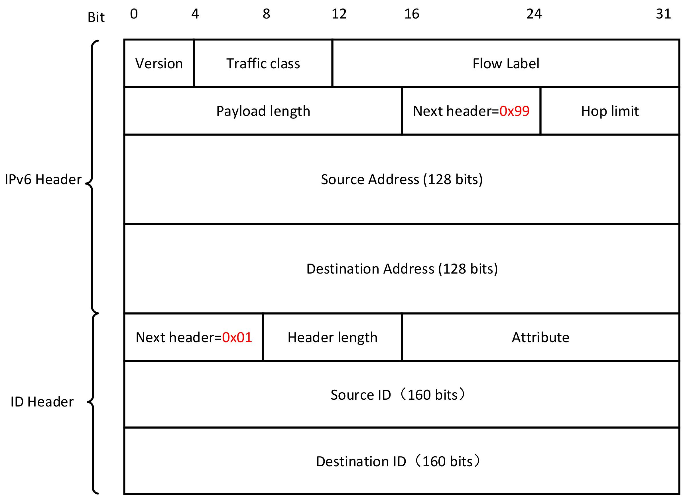
The replica selection or switching operation is performed by the IDP according to the packet header information worked at the network layer. The operation process is as follows: (1) a replica switching operation is performed both at the beginning of the chunk transmission and at the time the receiver’s transport layer judges the current link under heavy congestion; (2) the transport layer adds the identification information indicating the replica selection (RSI) to the ID packet header at the network layer, the ID packet header is an extension header of IPv6 packets as shown in Figure 2. When the “Next header” field of an IPv6 packet is 0x99, the next header represents the ID header. The RSI identifier can be one bit in “Attribute” field; (3) the intermediate router performs the replica selection operation locally when it receives a packet carrying this identification, i.e., RSI = 1. Of course, even if there is no identification information in the ID packet header indicating the execution of replica selection, the intermediate routers of the ICN network can also perform the IP address replacement operation according to their scenarios, such as mobility, multicast, multi-homing. We mainly consider here the multi-replica scenario for data acquisition. The IDP works in the network layer, and it decides how to select or replace the replica’s IP address in the packet header according to the scenario requirements, packet identification, local information, etc.
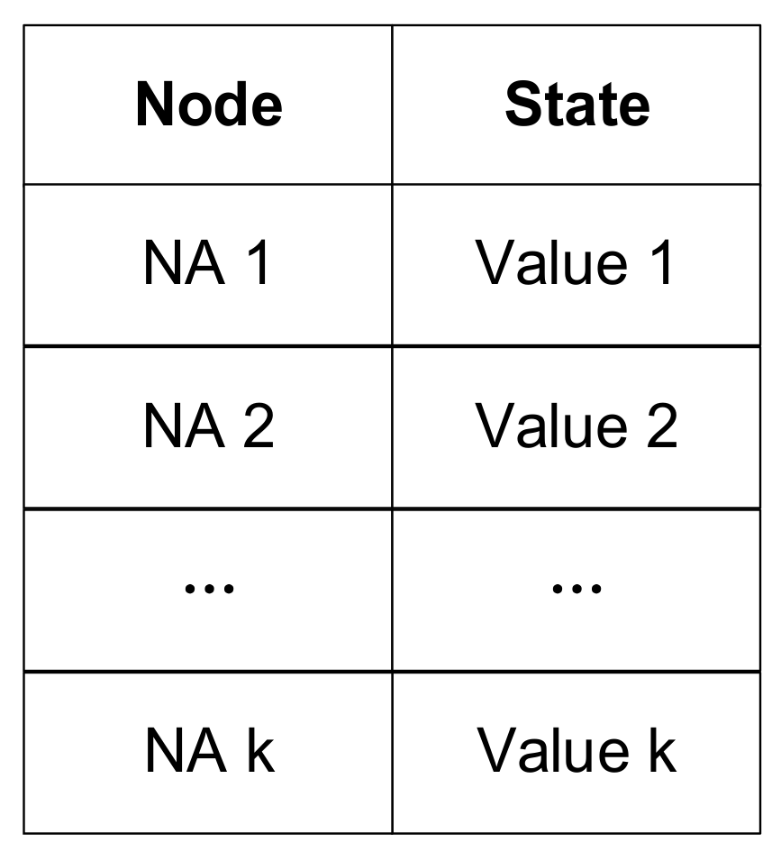
The replica selection is performed through NRS and the local NST. The requestor first obtains the list of IP addresses corresponding to the ID through NRS and then selects a suitable replica according to the NST maintained locally. The entries of NST include the replica node and the node state value as Figure 3 shows.
The replica node is uniquely identified and distinguished by the node’s network address, and the node state value indicates the ability of the corresponding replica node to provide data services. The calculation of the state value is defined as shown in Equation (5).
value = F X ,   X = ( x 1 , x 2 , , x h )
where X represents the indicators include network distance, RTT, replica node load, link capacity, etc. between the requester and replica nodes. F(X) can be flexibly defined according to the optimization objective.
In the literature [36], we proposed an enhanced replica selection approach, called ERS. The node state value is calculated using Equation (6), where w i i = 1 ,   2 ,   3 represents the weight assigned to each attribute. The network distance, loads of replica nodes, and path congestion degree are denoted by x 1 , x 2 , and x 3 , respectively.
Value = i = 1 3 w i × x i ,   w i > 0 ,   i = 1 3 w i = 1
As mentioned in ERS, the network distance (i.e., Hops) is evaluated by a traditional topology-based routing scheme based on shortest path algorithms [37], the load of replica nodes is calculated using the outstanding requests sent by the edge router to the corresponding replica node, and the path congestion degree is measured as RTT RTT base .

4.2. Congestion Control Algorithm

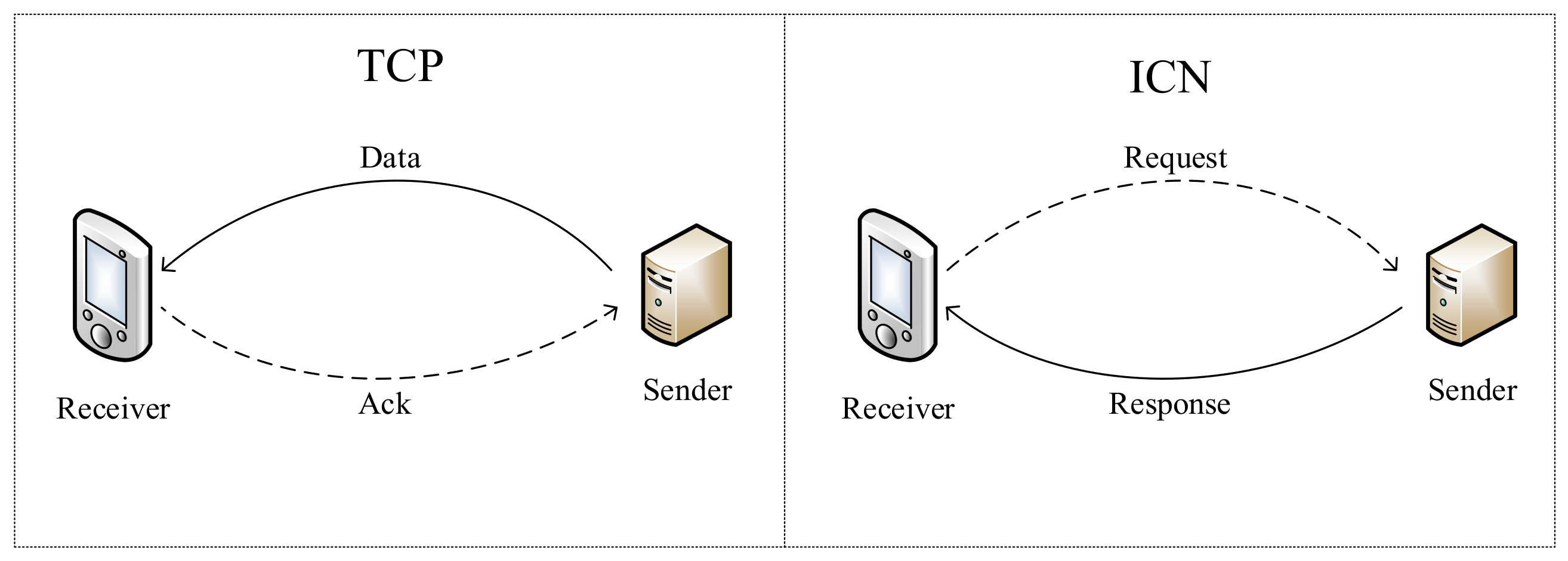
To accommodate the receiver-driven transmission mode of ICN, as shown in Figure 4, we adapt the TCP data packets and acknowledgment packets to the request packets and response packets in ICN, where the dashed lines are control packets and the solid lines are data packets.
During the chunk transmission, the request sending rate is adjusted by the congestion control module at the receiver to avoid link congestion while making full use of the spare bandwidth. ICN congestion control algorithms can refer to classical TCP congestion control algorithms such as Reno [29], Cubic [38], and BBR [39], but need to be redesigned to receiver-driven mode. For example, the chunk transmission of ICTP directly uses the Reno algorithm to adjust the rate. Receiver-driven congestion control algorithms usually maintain the required congestion control parameters, including congestion window (cwnd), RTT, and request queue at the receiver side to increase or decrease the request sending rate. In addition, the initial request sending rate at the receiver side can be determined based on the transmission history information, thus enabling a fast start during the congestion control algorithm.
The loss-based congestion control algorithm introduces the bufferbloat [40] problem making the end-to-end delay higher, and causing the problem of poor bandwidth utilization due to the inability to distinguish between random packet loss and congestion loss [41]. Therefore, the link capacity-based BBR algorithm is redesigned into a receiver-driven congestion control algorithm based on the ICN scenario instead of using a loss-based congestion control algorithm in this paper.
BBR no longer determines network congestion state by packet loss, and only retransmits packets after packet loss occurs. It calculates the RTT by matching the relationship between the request packets and the response packets. It obtains the link bandwidth based on the actual data volume carried in the response packets. Both current network bandwidth and RTT are dynamically detected and calculated. Only when the number of packets is greater than the bandwidth-delay product (BDP) as Equation (7) shows, BBR considers the network is congested.
B D P = B max   ×   RTT min
Among them, Bmax and RTTmin are two important parameters. BBR approximates the bottleneck bandwidth of the network as Bmax by continuously estimating the network transmission rate at the receiver and maintains a minimum RTT of 10 s called RTTmin. The BBR smoothly sends out the data requests according to the rate pacing_rate, and it controls the total amount of inflight data allowed to be sent to the current link based on the congestion window cwnd. The transmission rate and congestion window are calculated as shown in Equations (8) and (9), respectively.
p a c i n g _ r a t e = B max   ×   p a c i n g _ g a i n
c w n d = B D P   ×   c w n d _ g a i n
The pacing_gain and cwnd_gain are the transmission rate gain factor and the congestion window gain factor, respectively. The BBR algorithm can be divided into four states, STARTUP, DRAIN, PROBE_BW, and PROBE_RTT. The BBR starts from the STARTUP state and increases the transmission rate rapidly in a multiplicative incremental manner, with the pacing_gain and cwnd_gain both being 2/ln2. When the maximum bandwidth detected in the STARTUP state does not increase by more than 25% for three consecutive rounds, the BBR considers the link is full and enters the DRAIN state to empty the link queue of excess data, and the pacing_gain is reduced to ln2/2. When the size of the data in the link is reduced to BDP, the BBR enters the PROBE_BW state to detect the available bandwidth of the network link. If the BBR has not sampled a smaller RTT value in the last 10 s, it enters the PROBE_RTT state. During this state, cwnd is reduced to the size of 4 packets to reduce the inflight data in the network thus an accurate RTT can be detected, and this PROBE_RTT state usually lasts for 200 ms. The receiver-driven BBR congestion control algorithm is shown in Algorithm 2, and the time complexity of this algorithm is also O(1). Inflight represents the amount of data that is requested but has not received the corresponding response message yet.
Algorithm 2: Receiver-Driven BBR Congestion Control Algotirhm
1:   State ← Obtain the state of current transmission
2:   Inflight ← Obtain the size of inflight data of current transmission
3:   B ← Probe the realtime bandwidth of current transmission
4:   RTT ← Probe the realtime RTT of current transmission
5:   if State == STARTUP then
6:     pacing_gain ← 2/ln2
7:     cwnd_gain ← 2/ln2
8:   else if State == DRAIN then
9:     pacing_gain ← ln2/2
10:     cwnd_gain ← ln2/2
11:   else if State == PROBE_BW then
12:     pacing_gain ← Change according array [1.25, 0.75, 1, 1, 1, 1, 1, 1] periodically
13:   else if State == PROBE_RTT then
14:     cwnd ← 4
15:   BDP ← Equation (7)
16:   if not State == PROBE_RTT then
17:     cwnd ← BDP*cwnd_gain-Inflight
18:   pacing_rate ← Equation (8)
19:   Receiver sends request packets smoothly by pacing_rate

4.3. Transport Layer Protocol

The goal of ICN is to obtain a chunk with a specified ID from the network. For chunk-oriented characteristics in ICN, we designed the transport layer protocol (TLP) with the chunk as the basic transmission unit and adopt an ID-to-ID paradigm, where the two IDs denote the ID of chunk and the content requester, respectively. During the transmission, the ID of the chunk remains the same, and the IP address of the replica node can be changed so that a chunk can be well supported to be fetched from multiple replica nodes.
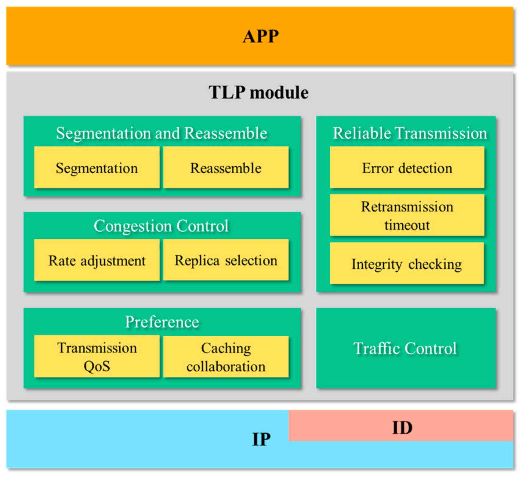
The TLP is designed to avoid overflowing its buffer or causing network congestion, and it needs to slice the chunk into segments and reassemble them at the receiver side as mentioned above. It is also necessary to ensure that the entire chunk is received correctly and completely before it is passed to the application. In other words, the transport layer protocol needs to implement segmentation and reassemble, congestion control, flow control, reliability, and integrity detection of the chunk [23]. Therefore, as shown in Figure 5, TLP includes five modules: segmentation and reassemble, flow control, preference, reliable transmission, and congestion control.
Next, we give a brief description of each of these five modules. The chunk needs to be further segmented at the transport layer to fit the MTU of the link. The transport layer header is added to every segment before it is handed over to the network layer, and these segments are reassembled at the receiver or cache nodes. To avoid receiver buffer overflow due to rate mismatch between the receiver and the sender, the flow control mechanism sets a sufficiently large (at least the size of the chunk) receiver buffer. Preferences are set to accommodate different application preferences for transmission, such as transmission Quality of Service (QoS) and caching collaboration. ICN routers can handle transport layer packets, so cooperative caching policies can be implemented with segments, such as cooperative control of whether the cached chunk is located in the center or at the edge of the network, and cooperative control of the number of cached copies. The reliable transport mechanism includes monotonically increasing packet numbers to avoid retransmission ambiguity and matching of request and response messages for RTT computation. Additionally, it uses checksum computation of the header and payload portions of transport layer packets to detect errors during transmission. To guarantee the reliable delivery of a chunk, the transport layer also needs to do integrity checks on whether the chunk is received in full and whether the chunk size is correct when the chunk is submitted upwards. Error recovery is achieved by timeout retransmission of segments. Congestion control uses the two-level congestion control mechanism proposed in this paper, i.e., rate adjustment and replica selection mechanism.
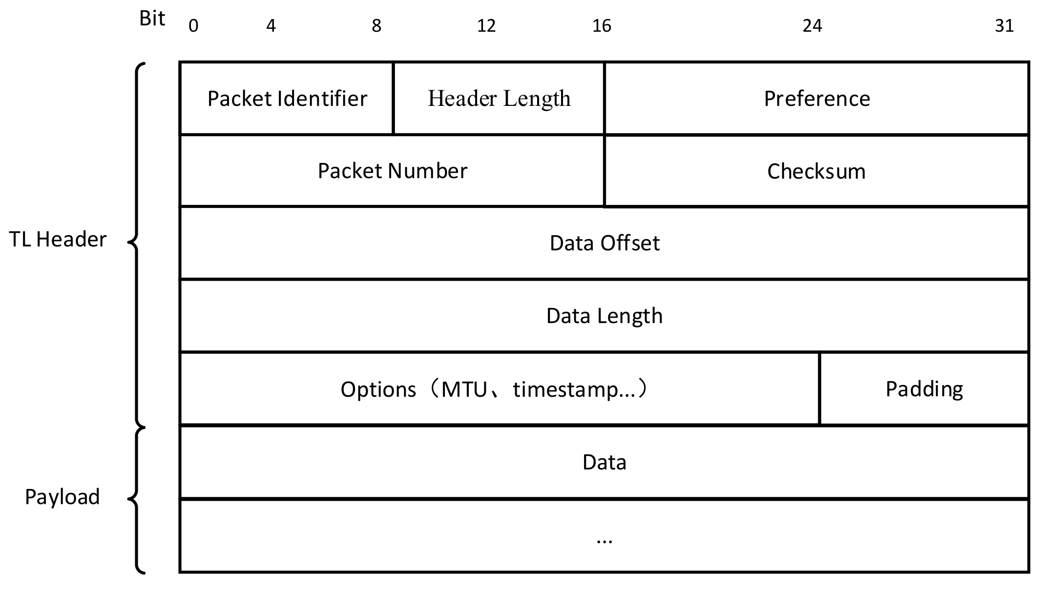
To correctly assemble a chunk and support the reception of different segments in disordered order, the offset position of the payload in the chunk is designed as a field in the transport layer header. To reduce the control signaling overhead and to support multiple response packets corresponding to one request packet at the receiver, the length information of the requested data is added to the request packet. Therefore, the receiver represents the starting position and the length of the requested data by the combination of (offset, length) in the packet header. With this information, the intermediate ICN routers can reorganize the segments from different data sources into one entire chunk. Then they store the chunk and register it to NRS, which becomes a replica node of this chunk [32]. In addition, for the replica switching scenario, even if the replica node is replaced, the received data is still valid and subsequent transmissions are continued from the offset location of the remaining data. Based on the above mechanisms, the transport layer (TL) packet is designed as shown in Figure 6.
In the Open System Interconnect (OSI) reference model, a service primitive [25] is an operation sent by a lower-layer protocol to provide some service to an upper-layer protocol through an interface. For chunk transmission, we define the request, listen, and response primitives, and the setting of transport-related parameters, including timeout time and chunk size, which are supported through options.
To support the transmission of the chunk, different packet identifiers are set, including chunk request (CREQ) packet, chunk response (CRES) packet, request (REQ) packet, response (RES) packet, and chunk transmission finish (CFIN) packet. The normal transmission process is that the receiver sends a CREQ packet, the sender replies with a CRES packet; the subsequent transmission proceeds by (REQ, n × RES) matching; the final transmission ends with the CFIN identification sent by the receiver. In the replica switching scenario, the receiver sends a CREQ packet again and fills the offset field with the location information where the current missing data starts into this packet. After receiving this CREQ packet, the new sender will check whether the local information for the transmission of the corresponding ID has been created. If not, the transmission can be continued after creating the transmission state.

5. Evaluation

The performance of 2LCCM is closely related to the performance of three aspects: replica selection method, congestion control algorithm, and switching strategy. The performance of the replica selection method has been extensively evaluated in the literature [36] and the parameters of Equation (6) is recommended to be w = { 0.757 ,   0.162 ,   0.081 } , thus this section focuses on evaluating the performance of switching strategy and the performance of the congestion control algorithm.

5.1. Performance of Switching Strategy

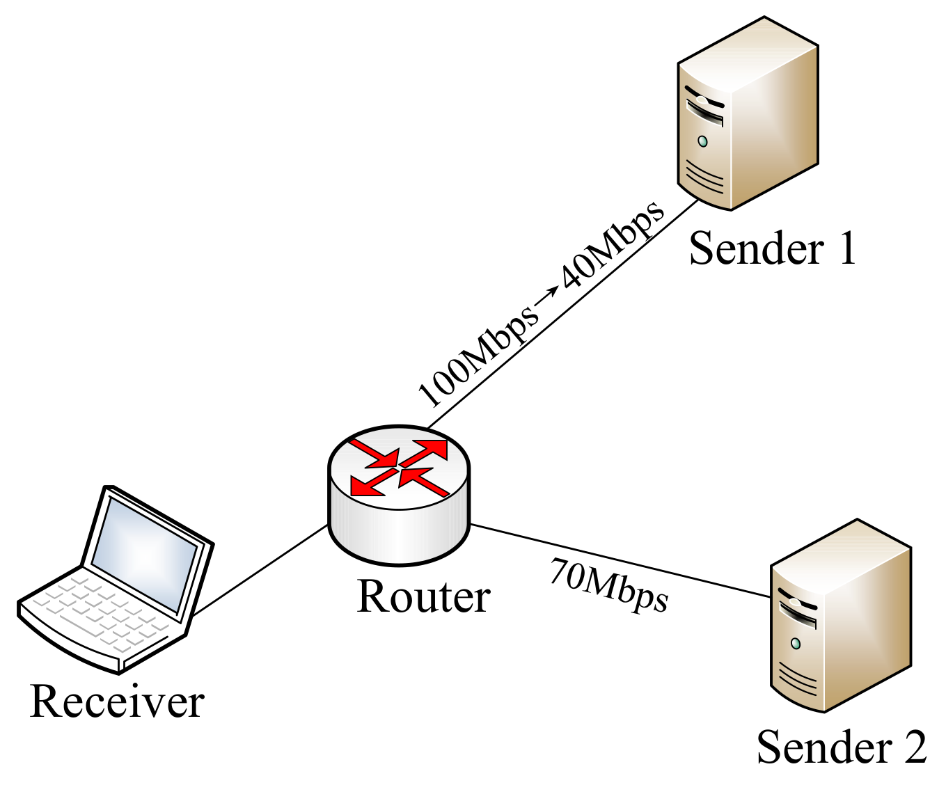
To evaluate the performance of the switching strategy, a simple topology is set up as shown in Figure 7. Three hosts are running the prototype SEANet protocol stack implemented by our group on Ubuntu 16.04 system, and the receiver is connected to both sender 1 and sender 2 through an ICN router.
For the first 4 s of chunk transmission, the link bandwidth between the receiver and sender 1 is 100 Mbps with an RTT of 20 ms, and the link bandwidth between the receiver and sender 2 is 70 Mbps. After 4 s, we assume severe congestion happens in the link between the receiver and sender 1. Then the corresponding available bandwidth drops to 40 Mbps and the RTT grows to 50 ms. In our experiments, the emulation tool NetEm [42] is used to vary network parameters and limit bandwidth. The size of the transmitted content is 100 MB. With such an experimental setup, we can simulate a real transmission scenario that a router on a transmission link has a bottleneck in forwarding due to bursty background traffic. In this case, the SEANet chunk transmission is affected, the available bandwidth decreases, and the RTT of packets increases due to queuing delay. These changes are detected by 2LCCM and timely congestion control is performed. Multiple sets of experimental results show that the switching process is stable with very small fluctuations in this experimental environment, so we selected one of the sets of experimental results for demonstrating the experimental performance.
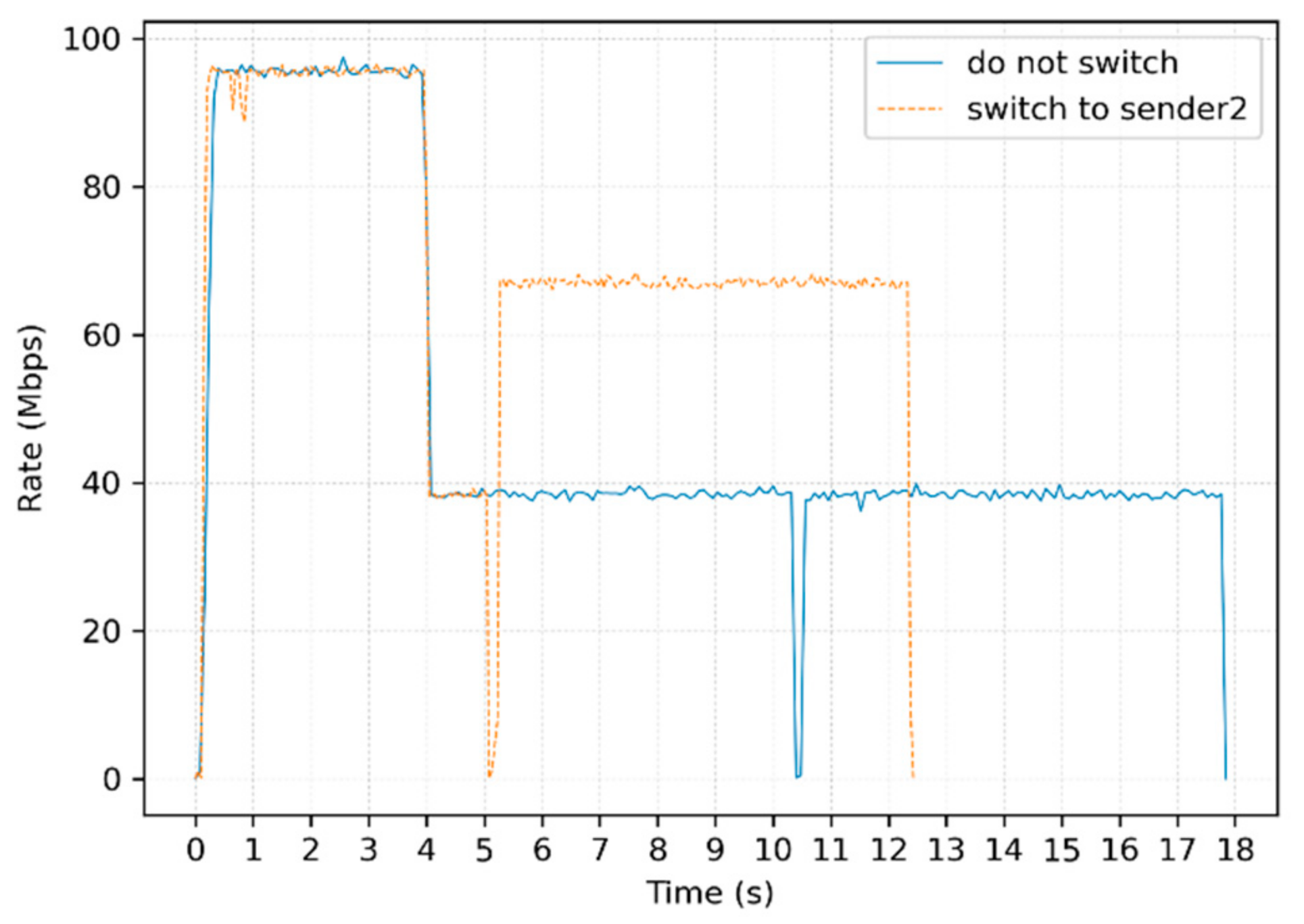
As shown in Figure 8, the solid blue line indicates the throughput rate variation of the chunk transmission without replica switching operation, that is to say, the receiver retrieves the entire chunk from sender 1. This transmission ends at about 17.92 s. There is a sudden drop of throughput rate at around 10.3 s. This is because the BBR algorithm enters the PROBE_RTT state to detect a smaller RTT, and cwnd is reduced to the size of 4 packets.
The orange-dashed line indicates that the receiver first retrieves data from sender 1 for about 4 s. Then, a sudden deterioration in bandwidth and RTT is detected, and the network is considered to be heavily congested. This transmission lasts about 1 s at a low bandwidth of 40 Mbps at sender 1, then it switches to sender 2 to retrieve the remaining data. There is a short rate burst time before switching to sender 2, and this chunk transmission finally ends at about 12.47 s.
As we can be seen from the experimental results, the receiver selects the sender 1 that has better data service performance between the two senders for data retrieval at first. After the state of a link towards sender 1 suddenly deteriorates, the congestion control module at the receiver quickly detects this change, reduces the request sending rate, and finds an alternative sender 2 with a better state to continue this chunk transmission. The experimental results show that the replica switching brings significant performance improvement, and the transmission time is reduced from 17.92 s to 12.47 s in our experimental scenario, an improvement of about 30.4%. It verifies the effectiveness of the two-level congestion control mechanism.

5.2. Performance of Receiver-Driven BBR Algorithm

To verify the performance of the above receiver-driven BBR congestion control algorithm, we compare the BBR algorithm with the Reno algorithm. The experiment was ran on two Ubuntu 16.04 hosts running the SEANet prototype system, the congestion control module of this system supports both BBR and Reno algorithms. The network environment was set to 100 Mbps of bandwidth and 10 ms of RTT, and the packet loss rate was 0, 0.1%, 1%, and 2%, respectively. The size of the chunk was 100 MB and the experiment results are shown in Figure 9.
From Figure 9, we can figure out that the difference in the transmission end time is not much when the packet loss rate is 0, 0.1% and 1% for the BBR algorithm. This is because that BBR does not use packet loss as a direct judgment factor affecting the transmission rate. However, with the increasing impact brought by packet loss, the throughout rate starts to become significantly fluctuating, and the transmission end time for the BBR increases from about 9.5 s to about 10.8 s when the packet loss rate varies from 1% to 2%. As the packet loss rate grows, the difference in transmission end time becomes bigger, and this is more evident for the Reno algorithm. When the packet loss rate is 2%, the transmission end time for the Reno is about 18.2 s, while that is 10.8 s for the BBR. The performance improvement of BBR over Reno is about 40.6%.
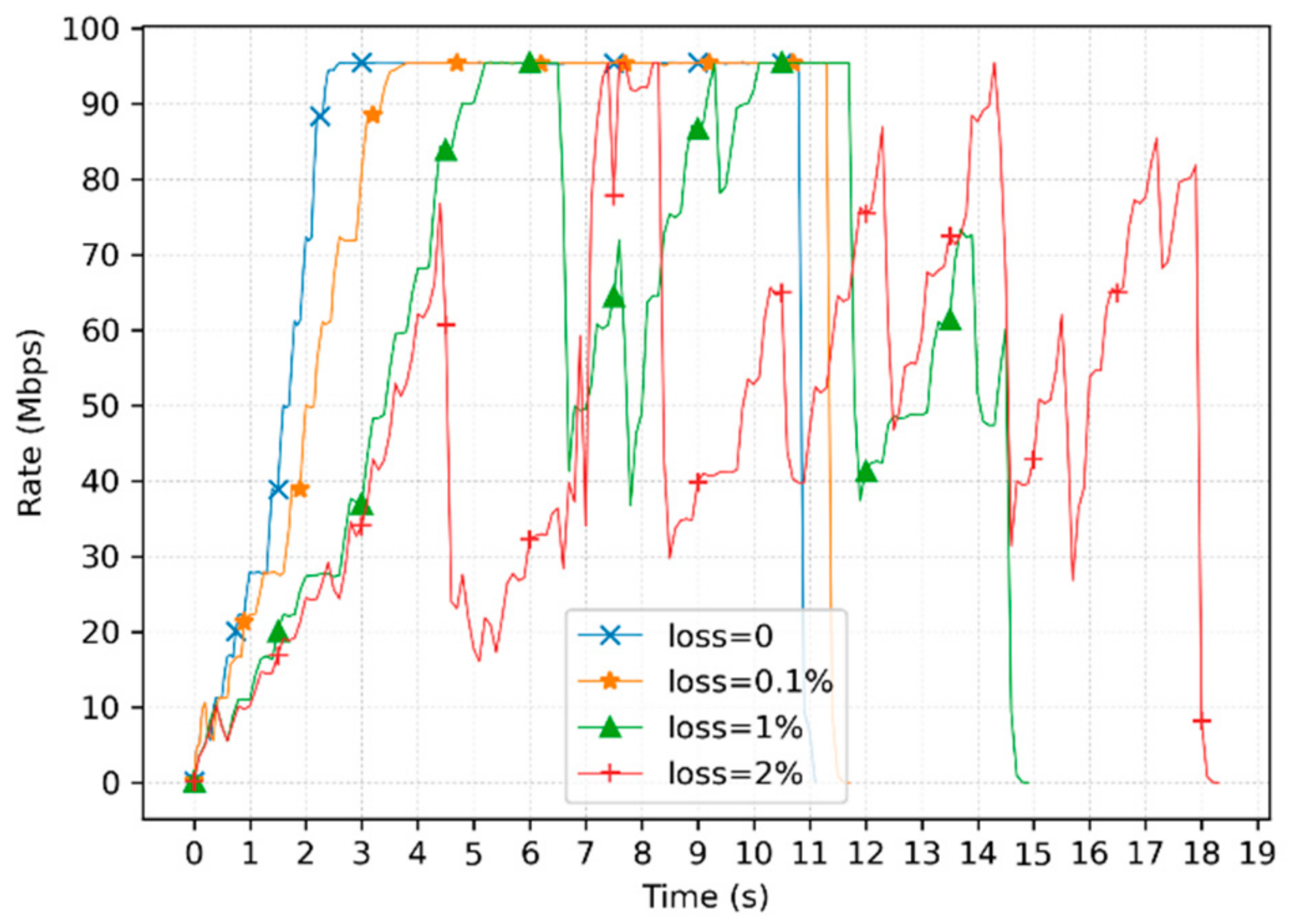
As shown in Figure 10, it can be further seen that the Reno algorithm significantly changes the transmission performance as the packet loss rate increases. When the packet loss rate is greater than 1%, the transmission end time increases significantly, and the waveform is clearly unstable. This is because Reno is a loss-based algorithm, and each packet loss event causes the congestion window to be halved, thus resulting in lower bandwidth utilization.
The experimental results show that the loss-based Reno algorithm causes a sharp drop in throughput rate as the packet loss rate grows, making the bandwidth utilization low. In contrast, the BDP-based BBR algorithm is insensitive to packet loss and makes the throughput rate reach almost 93% of the bandwidth even the packet loss rate is not zero, which accomplishes high bandwidth utilization.
In conclusion, this experimental result proves that using the BDP-based BBR congestion control algorithm has superior performance than using the loss-based Reno congestion control algorithm.

6. Conclusions

In this paper, a two-level congestion control mechanism, called 2LCCM, is proposed for ICN. When the transmission link is under heavy congestion, the replica location of a chunk will be changed by the replica selection method to avoid the current congestion path. When the transmission link is under light congestion, the sending rate of data requests is adjusted by the receiver-driven congestion control algorithm. The replica selection method is implemented based on a node state table, and the congestion control algorithm is based on the receiver-driven BBR algorithm. This paper also provides specific definitions of heavy congestion and light congestion. When the RTT becomes abnormally long or packets are continuously lost, heavy congestion is considered to have occurred. Additionally, a detailed description of the replica switching strategy is discussed. Finally, the experimental results show that switching to another replica for successive transmission under heavy congestion can effectively shorten the transmission time. It also shows that the BDP-based BBR algorithm has better bandwidth utilization than the loss-based Reno algorithm.
In the future, we will further investigate the replica selection method based on machine learning algorithms and the congestion control algorithm with intermediate nodes participating in congestion signal feedback. In addition, more extensive experiments will be conducted to verify the effectiveness of our proposed two-level congestion control mechanism.

Author Contributions

Conceptualization, Y.S., H.N. and X.Z.; methodology, Y.S., H.N. and X.Z.; software, Y.S.; writing—original draft preparation, Y.S.; writing—review and editing, Y.S., H.N. and X.Z.; supervision, X.Z.; project administration, X.Z.; funding acquisition, H.N. All authors have read and agreed to the published version of the manuscript.

Funding

This work was funded by Strategic Leadership Project of Chinese Academy of Sciences: SEANET Technology Standardization Research System Development (Project No. XDC02070100).

Institutional Review Board Statement

Not applicable.

Informed Consent Statement

Not applicable.

Data Availability Statement

Data sharing not applicable.

Acknowledgments

We would like to express our gratitude to Jinlin Wang and Jiaqi Li for their meaningful support with this work.

Conflicts of Interest

The authors declare no conflict of interest.

References

  1. Gupta, A.; Jha, R.K. A Survey of 5G Network: Architecture and Emerging Technologies. IEEE Access 2015, 3, 1206–1232. [Google Scholar] [CrossRef]
  2. Schulz, P.; Matthe, M.; Klessig, H.; Simsek, M.; Fettweis, G.; Ansari, J.; Ashraf, S.A.; Almeroth, B.; Voigt, J.; Riedel, I.; et al. Latency Critical IoT Applications in 5G: Perspective on the Design of Radio Interface and Network Architecture. IEEE Commun. Mag. 2017, 55, 70–78. [Google Scholar] [CrossRef]
  3. Xylomenos, G.; Ververidis, C.N.; Siris, V.A.; Fotiou, N.; Tsilopoulos, C.; Vasilakos, X.; Katsaros, K.V.; Polyzos, G.C. A survey of information-centric networking research. IEEE Commun. Surv. Tutor. 2014, 16, 1024–1049. [Google Scholar] [CrossRef]
  4. Proof-of-Concept for Data Service Using Information Centric Networking in IMT-2020. Available online: https://www.itu.int/itu-t/recommendations/rec.aspx?rec=13655 (accessed on 20 May 2020).
  5. Jacobson, V.; Smetters, D.K.; Thornton, J.D.; Plass, M.F.; Briggs, N.H.; Braynard, R.L. Networking named content. In Proceedings of the 5th International Conference on Emerging Networking Experiments and Technologies, Rome, Italy, 1–4 December 2009; pp. 1–12. [Google Scholar]
  6. Koponen, T.; Chawla, M.; Chun, B.-G.; Ermolinskiy, A.; Kim, K.H.; Shenker, S.; Stoica, I. A data-oriented (and beyond) network architecture. In Proceedings of the ACM SIGCOMM Computer Communication Review, Kyoto, Japan, 27 August 2007; pp. 181–192. [Google Scholar]
  7. Raychaudhuri, D.; Nagaraja, K.; Venkataramani, A. MobilityFirst: A robust and trustworthy mobility-centric architecture for the future internet. ACM SIGMOBILE Mob. Comput. Commun. Rev. 2012, 16, 2–13. [Google Scholar] [CrossRef]
  8. Dannewitz, C.; Kutscher, D.; Ohlman, B.; Farrell, S.; Ahlgren, B.; Karl, H. Network of Information (NetInf)—An information- centric networking architecture. Comput. Commun. 2013, 36, 721–735. [Google Scholar] [CrossRef]
  9. Wang, J.; Chen, G.; You, J.; Sun, P. SEANet: Architecture and Technologies of an On-site, Elastic, Autonomous Network. J. Netw. New Media 2020, 9, 1–8. [Google Scholar]
  10. Ren, Y.; Li, J.; Shi, S.; Li, L.; Wang, G.; Zhang, B. Congestion control in named data networking—A survey. Comput. Commun. 2016, 86, 1–11. [Google Scholar] [CrossRef]
  11. Zhang, J.; Ren, F.; Lin, C. Survey on transport control in data center networks. IEEE Netw. 2013, 27, 22–26. [Google Scholar] [CrossRef]
  12. Zhang, F.; Zhang, Y.; Raychaudhuri, D. Edge caching and nearest replica routing in information-centric networking. In Proceedings of the 37th IEEE Sarnoff Symposium, Newark, NJ, USA, 19–21 September 2016; pp. 181–186. [Google Scholar]
  13. Lee, M.; Song, J.; Cho, K.; Pack, S.; Kwon, T.; Kangasharju, J.; Choi, Y. Content discovery for information-centric networking. Comput. Netw. 2015, 83, 1–14. [Google Scholar] [CrossRef]
  14. Rozhnova, N.; Fdida, S. An effective hop-by-hop interest shaping mechanism for CCN communications. In Proceedings of the 2012 IEEE INFOCOM Workshops, Orlando, FL, USA, 25–30 March 2012; pp. 322–327. [Google Scholar]
  15. Zhang, F.; Zhang, Y.; Reznik, A.; Liu, H.; Qian, C.; Xu, C. A transport protocol for content-centric networking with explicit congestion control. In Proceedings of the 23rd International Conference on Computer Communications and Networks, Shanghai, China, 4–7 August 2014; pp. 1–8. [Google Scholar]
  16. Detti, A.; Salsano, S.; Cancellieri, M.; Blefari-Melazzi, N.; Pomposini, M. Transport-layer issues in information centric networks. In Proceedings of the 2nd edition of the ICN Workshop on Information-Centric Networking, Helsinki, Finland, 17 August 2012; pp. 19–24. [Google Scholar]
  17. Siddiqui, S.; Waqas, A.; Khan, A.; Zareen, F.; Iqbal, M.N. Congestion controlling mechanisms in content centric networking and named data networking—A survey. In Proceedings of the 2nd International Conference on Computing, Mathematics and Engineering Technologies (iCoMET), Sukkur, Pakistan, 30–31 January 2019; pp. 1–7. [Google Scholar]
  18. Xia, C.; Xu, M.; Wang, Y. A loss-based TCP design in ICN. In Proceedings of the 22nd Wireless and Optical Communications Conference, Chongqing, China, 16–18 May 2013; pp. 449–454. [Google Scholar]
  19. Fall, K.; Floyd, S. Simulation-based comparisons of Tahoe, Reno and SACK TCP. ACM SIGCOMM Comput. Commun. Rev. 1996, 26, 5–21. [Google Scholar]
  20. Carofiglio, G.; Gallo, M.; Muscariello, L. ICP: Design and Evaluation of an Interest Control Protocol for Content-Centric Networking. In Proceedings of the 2012 IEEE INFOCOM Workshops, Orlando, FL, USA, 25–30 March 2012; pp. 304–309. [Google Scholar]
  21. Potys, R.A.; Ali, N.M.; Marsh, I.; Osmani, F. NetInf TP: A receiver-driven protocol for ICN data transport. In Proceedings of the 2015 IEEE 23rd International Symposium on Quality of Service (IWQoS), Portland, OR, USA, 15–16 June 2015; pp. 267–272. [Google Scholar] [CrossRef]
  22. Wang, L.; Bayhan, S.; Kangasharju, J. Optimal chunking and partial caching in information-centric networks. Comput. Commun. 2015, 61, 48–57. [Google Scholar] [CrossRef]
  23. Saino, L.; Cocora, C.; Pavlou, G. CCTCP: A scalable receiver-driven congestion control protocol for content centric networking. IEEE Int. Conf. Commun. 2013, 3775–3780. [Google Scholar] [CrossRef] [Green Version]
  24. Arianfar, S.; Ott, J.; Eggert, L.; Nikander, P. ConTug: A transport protocol for content-centric networks. In Proceedings of the IEEE International Conference on Network Protocols, Kyoto, Japan, 5–10 October 2010; pp. 1–9. [Google Scholar]
  25. Agarwal, A.; Tahiliani, M.P. BCON: Back pressure based congestion avoidance model for Named Data Networks. In Proceedings of the 2016 IEEE International Conference on Advanced Networks and Telecommunications Systems, Bangalore, India, 6–9 November 2016; pp. 1–5. [Google Scholar]
  26. Schneider, K.; Yi, C.; Zhang, B.; Zhang, L. A practical congestion control scheme for named data networking. In Proceedings of the 3rd ACM Conference on Information-Centric Networking, Kyoto, Japan, 26–28 September 2016; pp. 21–30. [Google Scholar]
  27. Su, K.; Bronzino, F.; Ramakrishnan, K.K.; Raychaudhuri, D. MFTP: A clean-slate transport protocol for the information centric mobilityfirst network. In Proceedings of the 2nd International Conference on Information-Centric Networking, San Francisco, CA, USA, 30 September–2 October 2015; pp. 127–136. [Google Scholar]
  28. Wang, Z.; Luo, H.; Zhou, H.; Li, J. R2T: A Rapid and Reliable Hop-by-Hop Transport Mechanism for Information-Centric Networking. IEEE Access 2018, 6, 15311–15325. [Google Scholar] [CrossRef]
  29. Jacobson, V. Congestion avoidance and control. ACM SIGCOMM Comput. Commun. Rev. 1988, 18, 314–329. [Google Scholar] [CrossRef]
  30. Detti, A.; Blefari Melazzi, N.; Salsano, S.; Pomposini, M. CONET: A content centric inter-networking architecture. In Proceedings of the ACM SIGCOMM Workshop on Information-Centric Networking, Toronto, ON, Canada, 19 August 2011; pp. 50–55. [Google Scholar]
  31. Guoqing, W.; Jiang, L.; Xiuqin, L.; Shaoyu, Y.; Guojia, L. Modeling chunk-based content placement in information centric networking. J. China Univ. Posts Telecommun. 2017, 24, 44–50. [Google Scholar] [CrossRef]
  32. Zeng, L.; Ni, H.; Han, R. An incrementally deployable IP-compatible information-centric networking hierarchical cache system. Appl. Sci. 2020, 10, 6228. [Google Scholar] [CrossRef]
  33. Saino, L.; Psaras, I.; Pavlou, G. Hash-routing schemes for information centric networking. In Proceedings of the 3rd ACM SIGCOMM Workshop on Information-Centric Networking, Hong Kong, China, 12 August 2013; pp. 27–32. [Google Scholar]
  34. Kong, L.; Zhu, J.; Dai, R.; Sadat, M.N. Impact of distributed caching on video streaming quality in information centric networks. In Proceedings of the 2017 IEEE International Symposium on Multimedia, Taichung, Taiwan, 11–13 December 2017 ; pp. 399–402. [Google Scholar]
  35. Brakmo, L.S.; Peterson, L.L. TCP Vegas: End to End Congestion Avoidance on a Global Internet. IEEE J. Sel. Areas Commun. 1995, 13, 1465–1480. [Google Scholar] [CrossRef] [Green Version]
  36. Song, Y.; Ni, H.; Zhu, X. An enhanced replica selection approach based on distance constraint in ICN. Electronics 2021, 10, 490. [Google Scholar] [CrossRef]
  37. Eum, S.; Nakauchi, K.; Murata, M.; Shoji, Y.; Nishinaga, N. CATT: Potential based routing with content caching for ICN. In Proceedings of the 2nd Edition of the ICN Workshop on Information-Centric Networking, Helsinki, Finland, 17 August 2012; pp. 49–54. [Google Scholar]
  38. Ha, S.; Rhee, I.; Xu, L. CUBIC: A new TCP-friendly high-speed TCP variant. Oper. Syst. Rev. 2008, 42, 64–74. [Google Scholar] [CrossRef]
  39. Cardwell, N.; Cheng, Y.; Gunn, S.C.; Yeganeh, S.H.; Jacobson, V. BBR: Congestion-Based Congestion Control. Commun. ACM 2017, 60, 58–66. [Google Scholar] [CrossRef] [Green Version]
  40. Gettys, J.; Nichols, K. Bufferbloat: Dark buffers in the internet. Commun. ACM 2012, 55, 57–65. [Google Scholar] [CrossRef] [Green Version]
  41. Dong Hanze, G.Z. Performance improvement of BBR congestion control algorithm in wireless network. J. Harbin Inst. Technol. 2019, 51, 63–67. [Google Scholar] [CrossRef]
  42. Hemminger, S. Network emulation with NetEm. In Proceedings of the 6th Australian National Linux Conference, Canberra, Australia, 18–23 April 2005; pp. 1–9. [Google Scholar]
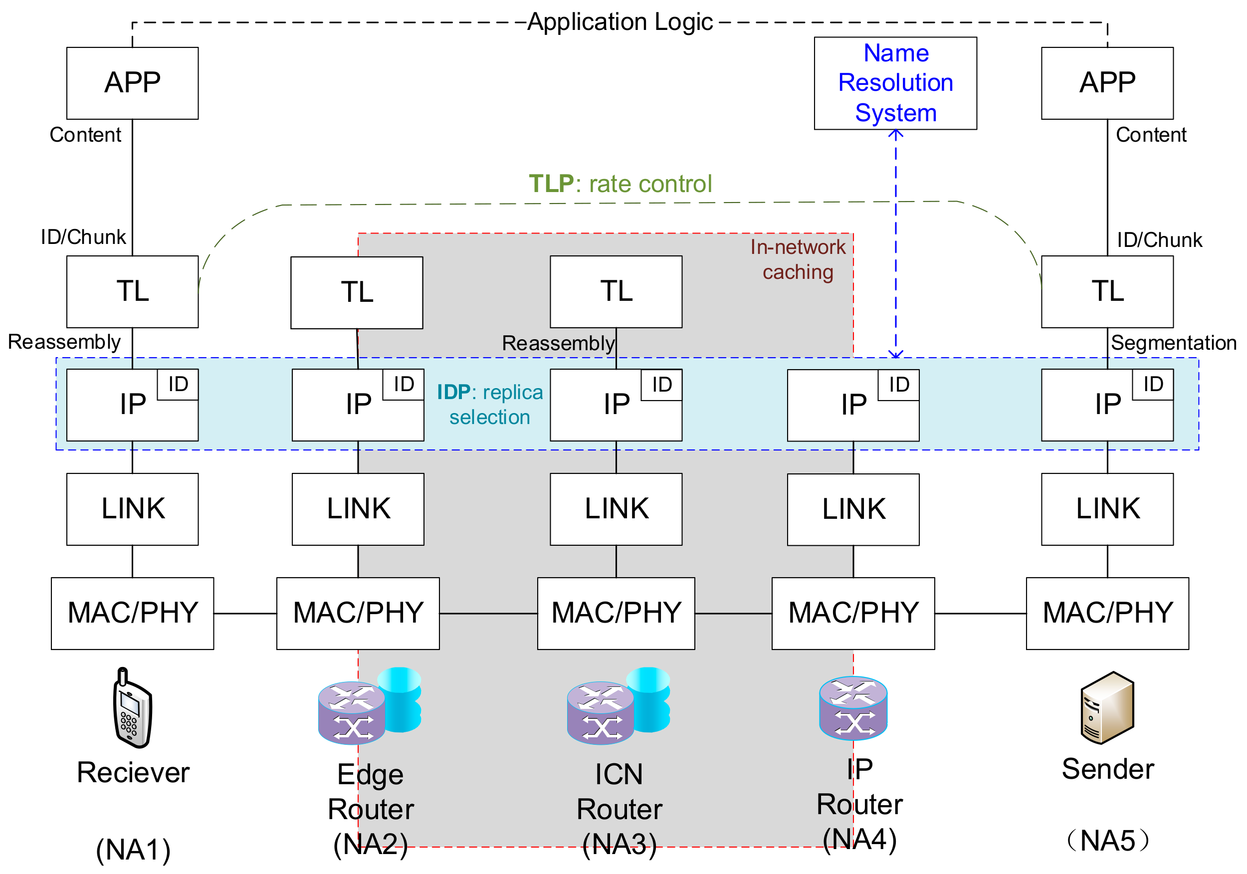
Figure 1. Protocol stack and architecture of 2LCCM.
Futureinternet 13 00149 g001
Figure 2. The packer format of ID header which is an extension header of IPv6.
Futureinternet 13 00149 g002
Figure 3. The data structure of NST.
Futureinternet 13 00149 g003
Figure 4. Transmission mode comparison of TCP and ICN.
Futureinternet 13 00149 g004
Figure 5. Module diagram of transport layer protocol (TLP).
Futureinternet 13 00149 g005
Figure 6. Packet format of transport layer (TL) header.
Futureinternet 13 00149 g006
Figure 7. Experimental topology.
Futureinternet 13 00149 g007
Figure 8. The rate changes over time with and without replica switching.
Futureinternet 13 00149 g008
Figure 9. Performance comparison of BBR and Reno.
Futureinternet 13 00149 g009
Figure 10. The performance of the Reno algorithm under different packet loss rates.
Futureinternet 13 00149 g010
Publisher’s Note: MDPI stays neutral with regard to jurisdictional claims in published maps and institutional affiliations.