Abstract
Generalized spatial modulation (GSM) technology is an extension of spatial modulation (SM) technology, and one of its main advantages is to further improve band efficiency. However, the multiple active antennas for transmission also brings the demodulation difficulties at the receiver. To solve the problem of high computational complexity of the optimal maximum likelihood (ML) detection, two sub-optimal detection algorithms are proposed through reducing the number of transmit antenna combinations (TACs) detected at the receiver. One is the maximum ratio combining detection algorithm based on repetitive sorting strategy, termed as (MRC-RS), which uses MRC repetitive sorting strategy to select the most likely TACs in detection. The other is the maximum ratio combining detection algorithm, which is based on the iterative idea of the orthogonal matching pursuit, termed the MRC-MP algorithm. The MRC-MP algorithm reduces the number of TACs through finite iterations to reduce the computational complexity. For M-QAM constellation, a hard-limited maximum likelihood (HLML) detection algorithm is introduced to calculate the modulation symbol. For the M-PSK constellation, a low-complexity maximum likelihood (LCML) algorithm is introduced to calculate the modulation symbol. The computational complexity of these two algorithms for calculating the modulation symbol are independent of modulation order. The simulation results show that for GSM systems with a large number of TACs, the proposed two algorithms not only achieve almost the same bit error rate (BER) performance as the ML algorithm, but also can greatly reduce the computational complexity.
1. Introduction
As a new multi-input multi-output (MIMO) antenna technology, spatial modulation (SM) has received considerable attention in the field of wireless communication [1,2,3]. However, since SM technology activates only one antenna per time slot to transmit data, its transmission rate is obviously lower than that of traditional MIMO technology. To solve the problem of the transmission rate of SM technology, generalized spatial modulation (GSM) technology was proposed in [4,5].
In a GSM system, multiple antennas are activated to transmit the same or different modulation symbols in each time slot. Therefore, the spectrum efficiency of GSM technology is higher than SM technology. If the GSM system transmits the same modulation symbols on the selected transmit antenna combinations (TACs), it not only eliminates inter-channel interference (ICI), but also imports spatial diversity, which improves the accuracy of signal detection at the receiver. However, the structure inevitably increases the detection complexity at the receiver. To reduce the detection complexity and approximate the BER performance of the ML detector, various research results have been proposed in [6,7,8,9,10,11,12,13]. Moreover, to make full use of the limited spectrum resources, more researchers have begun to focus on the adaptation of 5G architectures for future NetApps and verticals, and the white spaces in frequency bands [14,15].
An improved sphere decoding (SD) detection algorithm was proposed in [6]. The enhanced SD algorithm can efficiently reduce the detection complexity by reducing the number of search tree branches of the traditional SD detector. In [7], tree-search SD and path-search SD algorithms were proposed to reduce the complexity of the SD algorithm in the GSM system. An ordered block minimum mean square error (OB-MMSE) detection algorithm was proposed in [8]. Firstly, the pseudo inverse operation is used to sort the possible TACs, and then for each ordered TAC the minimum mean square error (MMSE) detection algorithm is used to detect the modulation symbols. It can achieve near-ML performance with low-complexity. A low complexity grouping detection algorithm was presented in [9]. The transmitter divided the transmit antennas into several groups according to the number of active antennas and each group activated one antenna to transmit the modulation symbol, and the receiver carried out the packet successive detection. In [10], an efficient index-to-bit mapping for spatial bits based on Gray coding was proposed to improve the spatial bit-error rate (BER). A fully GSM (F-GSM) system was proposed in [11]. In an F-GSM system, the increment of data transmission rate is proportionated to the base-2 logarithm of the number of the transmit antennas. The F-GSM system has a higher data transmission rate compared to the conventional GSM. The optimization framework of GSM and generalized orthogonal spatial modulation (GQSM) were proposed in [12], which extended the spatial constellation. A probability-ordering-based sphere decoding detector for jointly mapping generalized spatial modulation system was proposed in [13], which can reduce the computational complexity of the ML detector.
To obtain the near-ML detection performance and lower complexity, two suboptimal detection algorithms are proposed in this paper. The two detectors can reduce the computational complexity by reducing the number of the TACs. For the estimation of the modulation symbol, the HLML algorithm [16] for M-QAM constellation and LCML algorithm [17] for M-PSK constellation are adopted. The computational complexity of estimating the modulation symbol is independent of the modulation order, so the complexity of symbol detection is greatly reduced.
The rest of the paper is organized as follows. The system model of GSM is presented in Section 2. The proposed two suboptimal detection algorithms are illustrated in Section 3 and Section 4, respectively. The simulation results and computational complexity analysis of the two proposed algorithms are presented in Section 5. Finally, we conclude the paper in Section 6.
Notation: Boldface uppercase letters denote matrices; boldface lowercase letters denote vectors. , , and represent the transpose, Hermitian transpose, inverse, pseudo-inverse operation of a vector or a matrix, respectively. denotes the floor operation. is the -norm of a vector or a matrix. stands for the absolute value of a complex number or the cardinality of a given set. indicates the operation of rounding a real number to the nearest integer. is the modulo operation. and represent the real and imaginary parts of a complex-value variable, respectively. and represent the field of real and complex numbers, respectively. denotes the binomial coefficient, which is given by . If , the binomial coefficient . , where is a power of two.
2. System Model
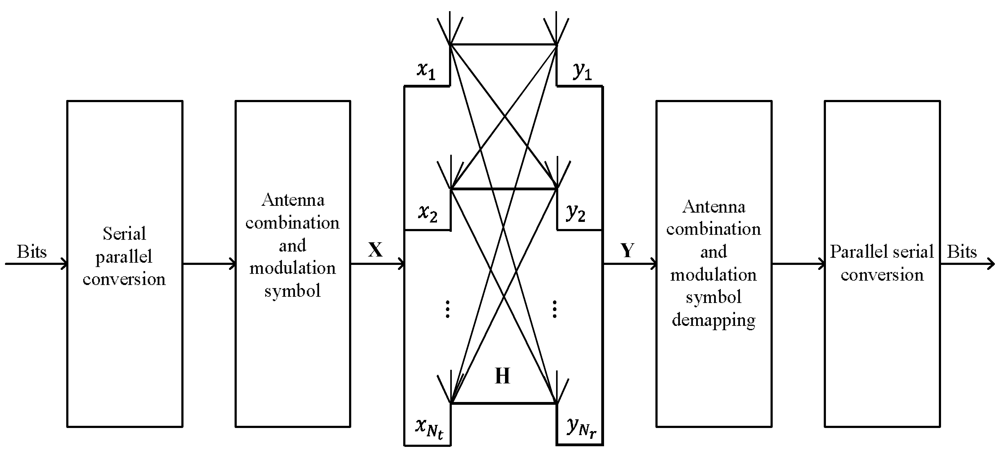
Consider a GSM system with transmit antennas and receive antennas. The block diagram of GSM is shown in Figure 1. The source binary sequence is transmitted from antennas, , and all activated antennas transmit the same M-QAM or M-PSK symbols. When choosing active transmit antennas out of ones, there are possible transmit antenna combinations (TACs). Among these TACs, only TACs are chosen to convey information. In each time slot, the information bits with length of are divided into two parts: the TACs selection bits and the modulation symbol bits, where information bits are used to map the TAC indices and information bits are mapped the constellation symbol , where denotes the modulation symbol. and represent the modulation order and the modulation symbol set, respectively. The transmitted signal vector with non-zero elements can be expressed as . We only study the GSM system that transmits same symbol in each active transmit antenna, that is, .
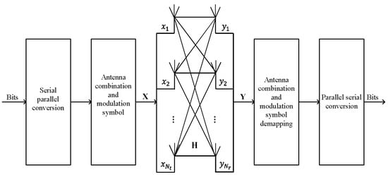
Figure 1.
The block diagram of GSM system with transmit antennas and receive antennas.
It is assumed that the -th TACs is used to transmit modulation symbols under the condition that the channel is Rayleigh fading channel and the channel gain is constant within a symbol period. Then the received signal vector can be expressed as
where , is an additive white Gaussian noise with mean 0 and variance . is the channel gain matrix, and each element of obeys complex Gaussian distribution with mean 0 and variance 1. is the submatrix with columns of corresponding to the TAC set .
Since all activated antennas transmit the same symbol , the system model can be rewritten as
where stands for the -th element in TAC set , denotes the -th column of the channel gain matrix , represents the sum of the column vectors of corresponding to the -th TAC.
For GSM system, ML detection algorithm given in [18] can be formulated as
where , with is defined as the set of active transmit antennas in the -th TAC, and represents the set of -dimensional modulation symbol vectors.
The ML detection can also be rewritten as
If only real-valued multiplications and divisions are considered, the computational complexity of ML detection algorithm is in the GSM system that transmits the same symbols. We can say that the ML algorithm has a high complexity and it is difficult to implement, especially in large-scale GSM systems.
3. MRC-RS Detection Algorithm
For signal detection in GSM, the computational complexity of the ML algorithm grows exponentially with the number of transmit antennas. To reduce the computational complexity while keeping the near-ML BER performance, we propose a new detection algorithm based on maximum ratio combining and repetitive sorting strategy, termed as MRC-RS detection algorithm.
In the MRC-RS algorithm, the TAC and modulation symbol can be estimated through three steps. In the first step, half of the most likely TACs are reversed for detection by repetitive sorting, which can greatly decrease the computational complexity. In the second step, quantitate the transmit symbol using the HLML and LCML detector for M-QAM and M-PSK constellations, respectively. At last, the TAC and modulation symbol are estimated jointly using the ML detector. Due to the reduction of the number of TACs, the proposed algorithm is a suboptimal detection algorithm.
3.1. Sort TACs
In the proposed detector, an ordering algorithm is firstly developed to sort the TACs.
with length of denotes the weight vector and the MRC value corresponding to -th TAC can be represented as
where , and the symbol can be expressed as
where , is the sum of the column vectors of corresponding to the -th TAC.
Then sort the weight vector in descending order and obtain the ordered TACs as
where is defined as a sorting function for reordering the elements of the input vector in descending order, and , are the indices of the maximum and minimum value in vector , respectively.
In the next, we select the two most likely TACs corresponding to and , and delete the duplicate antenna indices to obtain antenna set . We also obtain new TACs by deleting the TACs that do not include any antenna in set . Then the MRC algorithm is used to calculate the MRC value of new TACs and get a new weight vector with a length of . The MRC value of -th TAC in new TACs can be calculated as
where , represents the sum of channel state vectors corresponding to the -th TAC, that is,
Meanwhile, the new weight vector is resorted in descending order, and we obtain the ordered TACs as
where and are the indices of the maximum and minimum values in , respectively. Then we only reserved most likely TACs to estimate the modulation symbols.
3.2. Quantitate Symbols
This subsection describes modulation symbol detection for the M-QAM and M-PSK constellations.
For the M-QAM constellation, if the modulation signal set with is a square or rectangular lattice constellation, it can be viewed as the Cartesian product of two sets and . , , where and are powers of 2.
We calculate the estimated modulation symbol corresponding to the -th TAC in TACs.
where , represents the sum of column vectors corresponding to the -th TAC, that is,
The quantitated modulation symbol corresponding to the -th TAC can be expressed as
For the M-PSK constellation, the amplitude of its constellation point is 1. We also calculate the estimated value of the modulation symbol corresponding to the -th TAC among TACs using Equations (11) and (12), where . is the included angle between and the positive real axis of the complex plane. The quantization of is shown as follows
3.3. Estimate Solution
In this subsection, the ML algorithm is applied to estimate the transmit antenna combination and the transmit symbol. The Euclidean distance between the received signal vector and the -th TAC and its corresponding transmitted symbol is calculated. The equivalent TAC and transmit signal with the minimum Euclidean distance from is taken as the final detection signal, that is, the detector is equivalent to the optimal ML algorithm by choosing the optimal estimation in TACs as
where represents the position of the TAC corresponding the minimum Euclidean distance between -th TAC and its corresponding transmit symbol and .
The proposed MRC-RS detection algorithm can be described in Table 1.

Table 1.
Proposed MRC-RS detector.
4. MRC-MP Detection Algorithm
In this section, a maximum ratio combining detection algorithms based on the iterative idea of the orthogonal matching pursuit, termed as the MRC-MP algorithm, is proposed. The MRC-MP algorithm can be divided into three stages. In the first stage, the TACs are constructed combining with the iteration idea of the OMP algorithm. By multiple iterations, new TACs with fewer antenna combinations are obtained. In the second stage, the transmit symbol is quantitated. In the third stage, the TAC and the modulation symbol are estimated jointly. The second and third stages are same as that of the MRC-RS algorithm.
The specific implementation steps are as follows.
Step 1: Initialize the required variables, the iteration counter and residual are and , respectively. The active antenna index set is , and is an empty set.
Step 2: In the -th iteration, the MRC value between and is calculated as
where is the -th column of the channel gain matrix , .
Step 3: Calculate the average value of MRC values in the -th iteration and find out the qualified antenna indices.
where denotes the average value of MRC values.
All MRC values are compared with . If the MRC value is greater than the average value , that is, , the antenna index corresponding to the MRC value is added into the set ,
where .
Step 4: The signal is estimated using the least square method in the -th iteration. For each entry contained in set , each signal can be obtained as
where represents the -th column of channel gain matrix , denotes the -th element in set .
Step 5: The residual is updated in -th iteration,
Step 6: Judge the iteration termination condition. If , stop the iteration and output antenna index sets ; otherwise, and return to Step 2 to continue the iteration.
Step 7: antenna index sets are obtained through iterations. Combining the antenna index sets, remove the duplicate antenna indices, and only leave the non-duplicate antenna indices. Thus, we obtain the new TACs by deleting the TACs that do not include any of the elements in set from all the TACs. The new TACs are considered as quantified TACs with high possibility.
Step 8: Quantitate the modulation symbol.
Step 9: The TAC and the modulation symbol are estimated using ML algorithm.
The proposed MRC-MP detection algorithm can be described in Table 2.
Table 2.
Proposed MRC-MP detector.
5. Simulation Results and Computational Complexity Analysis
In this section, the BER performance and the computational complexity of the proposed algorithms for GSM systems are simulated under the assumption of perfect channel state information. In all simulations, the SNR represents the ratio of the symbol power to the noise power. In this paper, the computational complexity is defined as the total number of the real-valued multiplications and divisions involved in an algorithm.
5.1. Simulation Result and Computational Complexity Analysis for M-QAM Constellation
5.1.1. Simulation Result
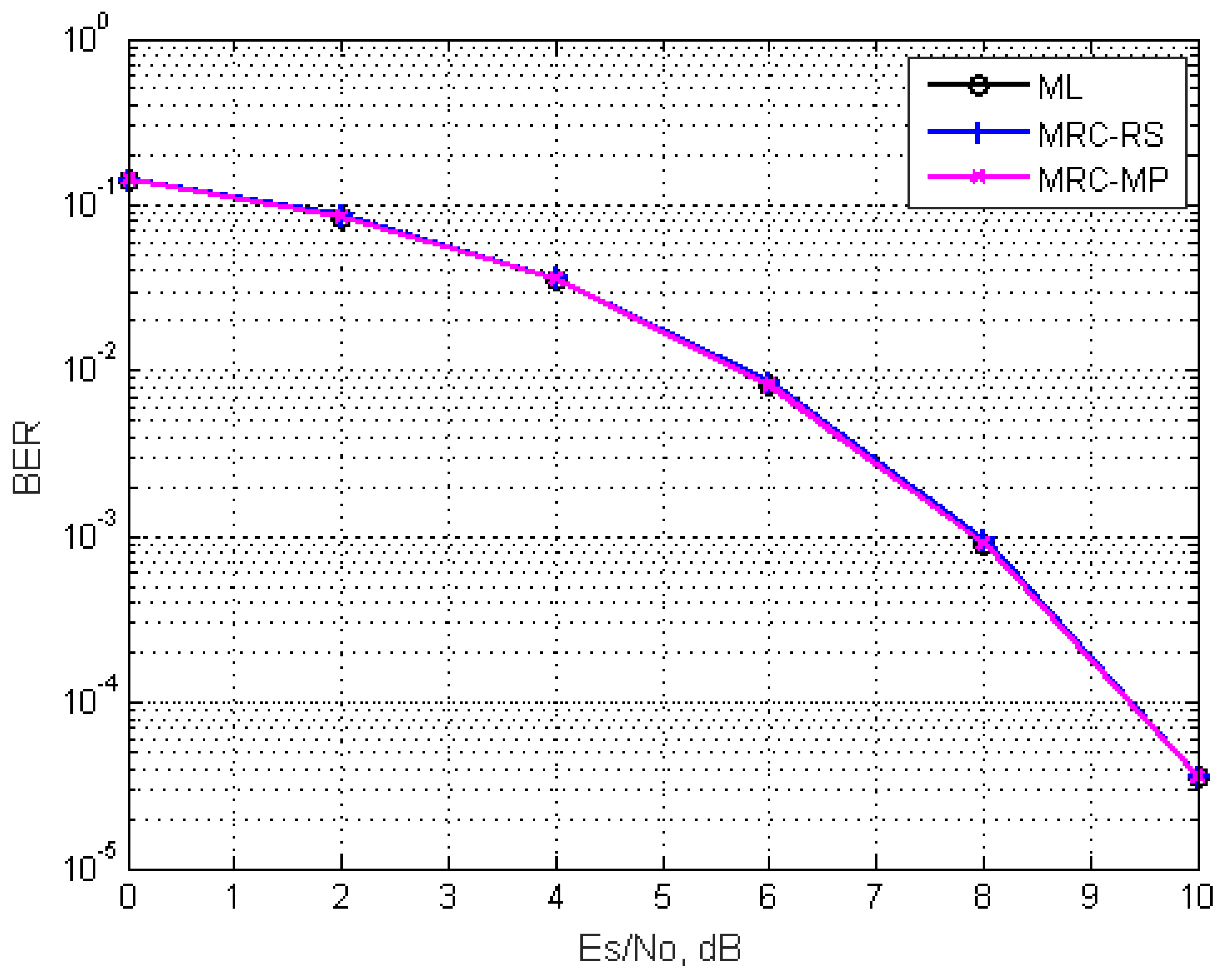
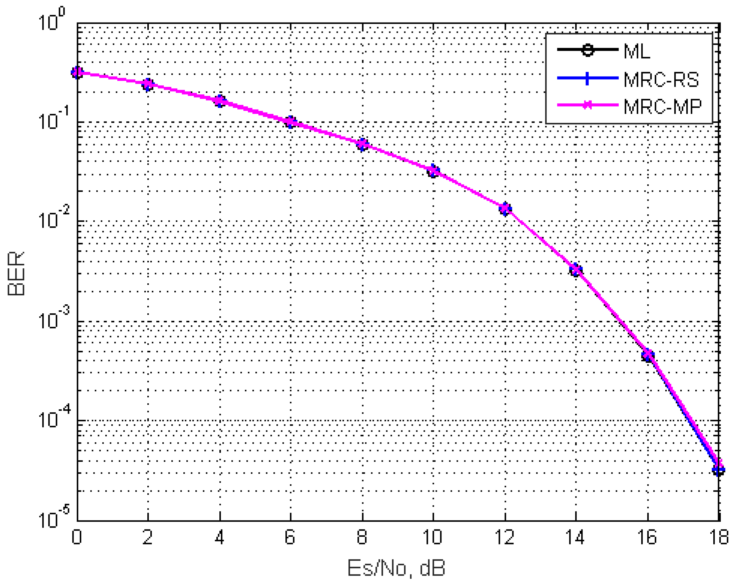
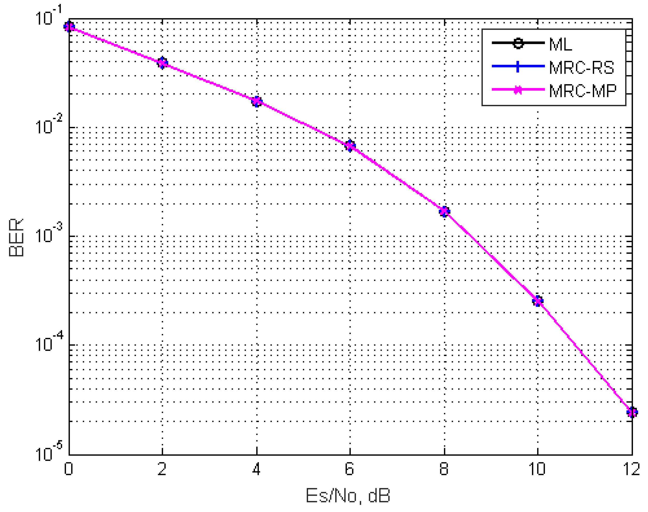
Figure 2 and Figure 3 show the BER performance comparison of the proposed algorithms and ML algorithm for a GSM system in two scenarios with (1) , , , and (2) , , , . It can be seen from Figure 2 and Figure 3 that the BER performance of the above-mentioned algorithms is almost the same in the whole SNR range.
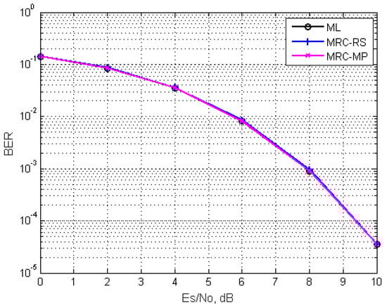
Figure 2.
BER performance comparison of the proposed detectors and ML detector for GSM system in the presence of Rayleigh fading channel and perfect channel state information at the receiver with , , and .
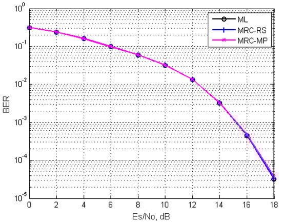
Figure 3.
BER performance comparison of the proposed detectors and ML detector for GSM system in the presence of Rayleigh fading channel and perfect channel state information at the receiver with , , and .
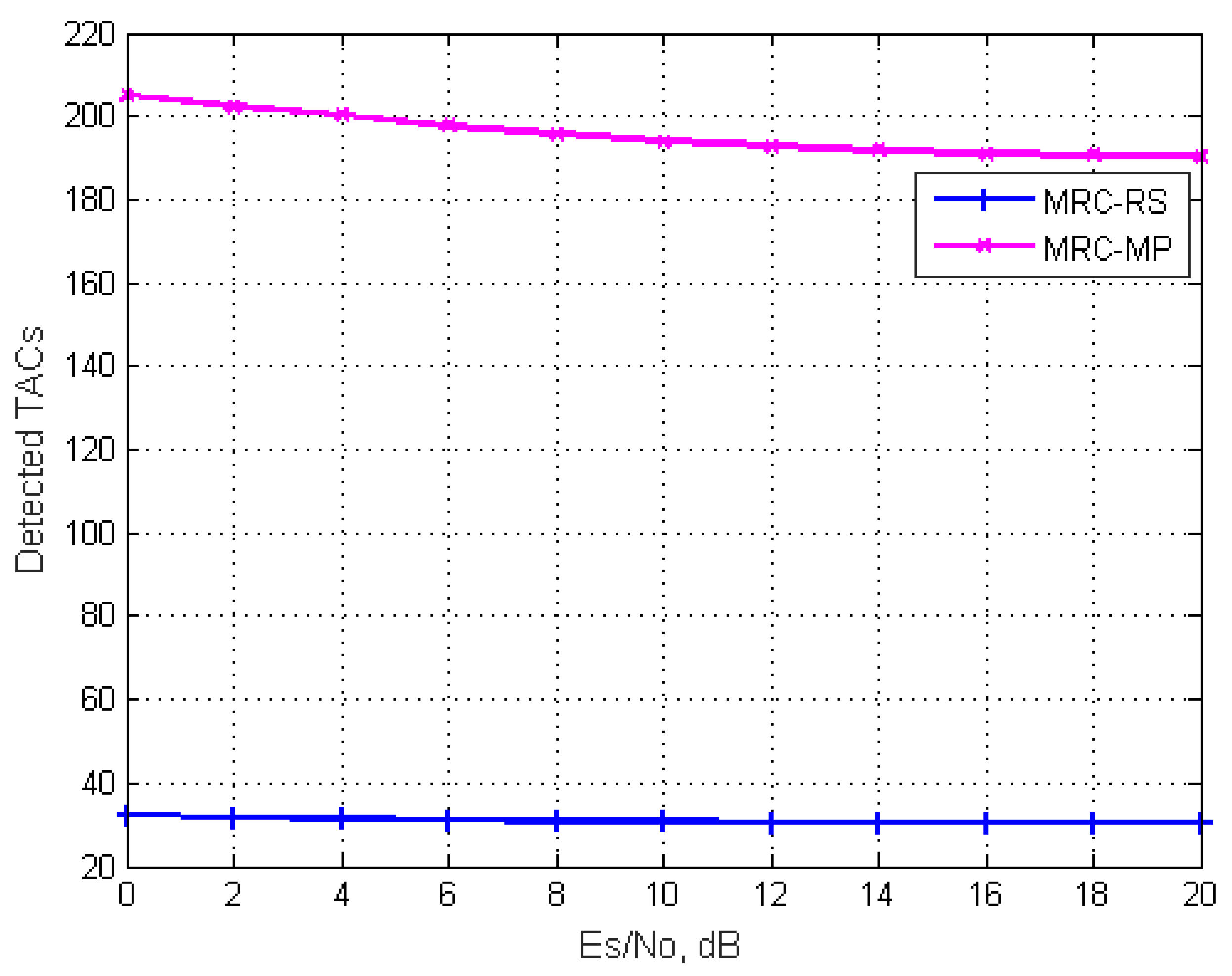
It needs to be verified whether the proposed two algorithms can greatly reduce the number of TACs detected by the receiver. Figure 4 and Figure 5 depict the average number of TACs detected by the MRC-RS and MRC-MP algorithms at the receiver in two scenarios: (1) , , , and (2) , , , .
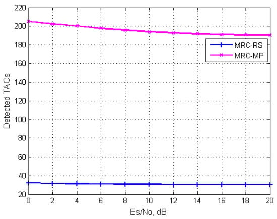
Figure 4.
Average number of TACs detected by MRC-RS and MRC-MP algorithms for a GSM system with , , and .
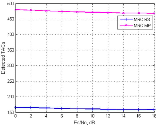
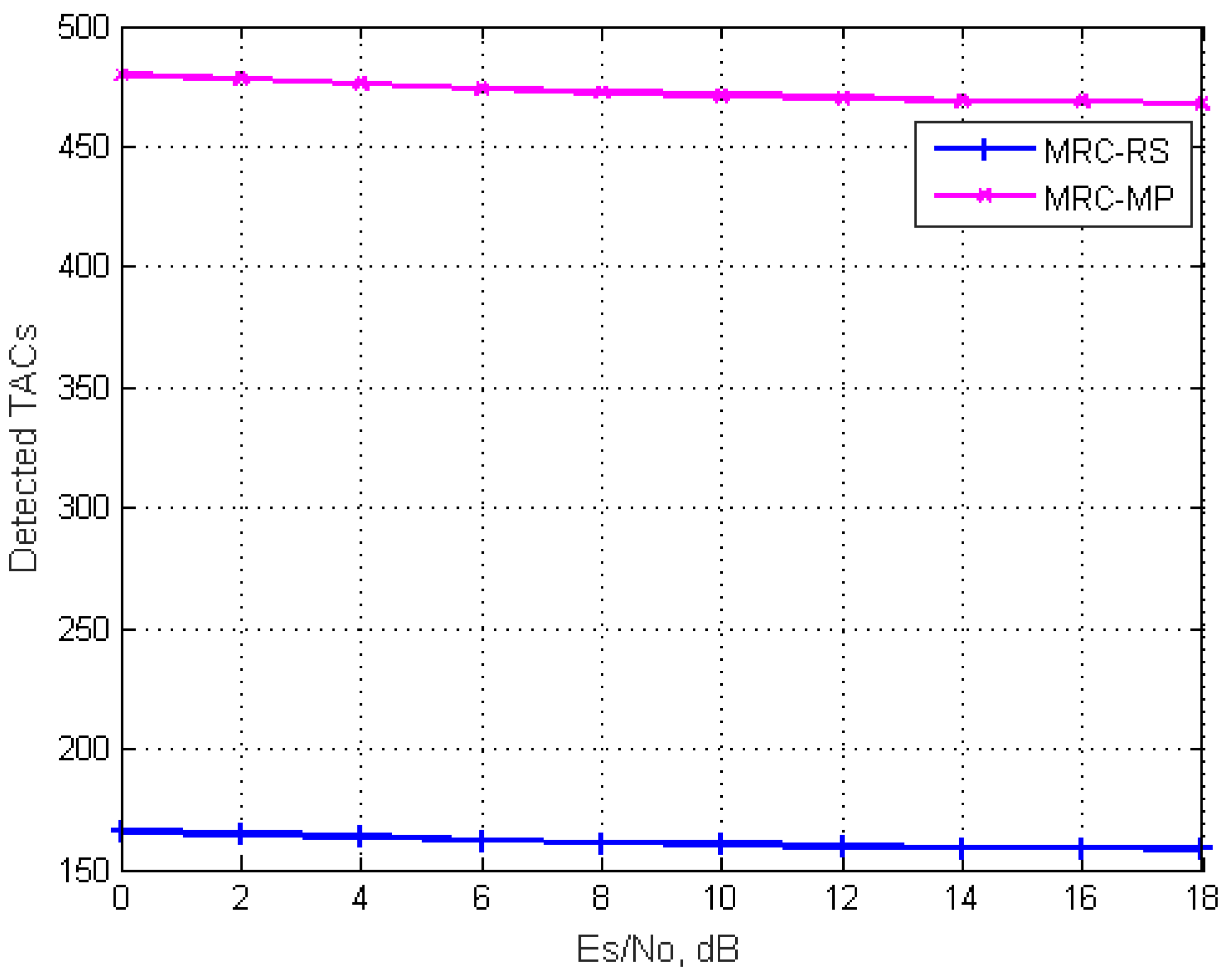
Figure 5.
Average number of TACs detected by MRC-RS and MRC-MP algorithms for a GSM system with , , and .
When and , the number of TACs for a conventional GSM system is 256. It can be seen from Figure 4 that the MRC-RS algorithm finally detects about 30 TACs under different SNRs, which is about 12% of the total TACs. The detected TACs by MRC-MP algorithm decrease gradually with the increase of SNR. About 190 TACs are detected when the SNR is 20 dB, which is about 74% of the total TACs.
When and , the number of TACs for the conventional GSM system is 512. We can see from Figure 5 that the number of TACs detected by MRC-RS and MRS-MP algorithms is 158 and 467, which is about 30% and 90% of the total TACs, respectively.
5.1.2. Computational Complexity Analysis
The computational complexity of ML, MRC-RS and MRC-MP detectors are listed in Table 3.
Table 3.
Comparison of above-mentioned detectors for M-QAM constellation.
is the number of TACs for the conventional GSM system. is the number of TACs used in MRC-RS algorithm. represents the total number of qualified antenna indices in the -iteration of MRC-MP algorithm. is the number of TACs
selected by the MRC-MP algorithm.
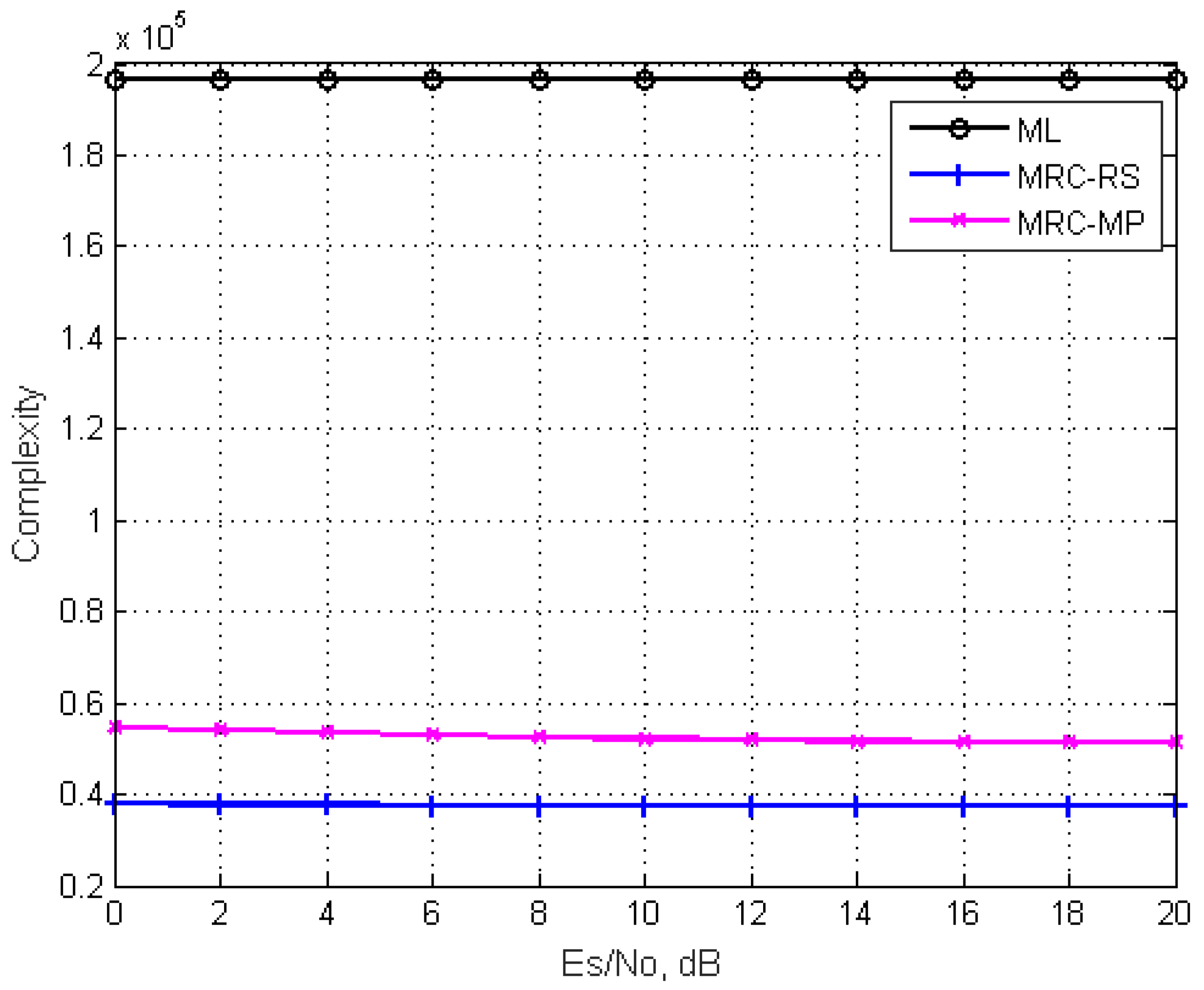
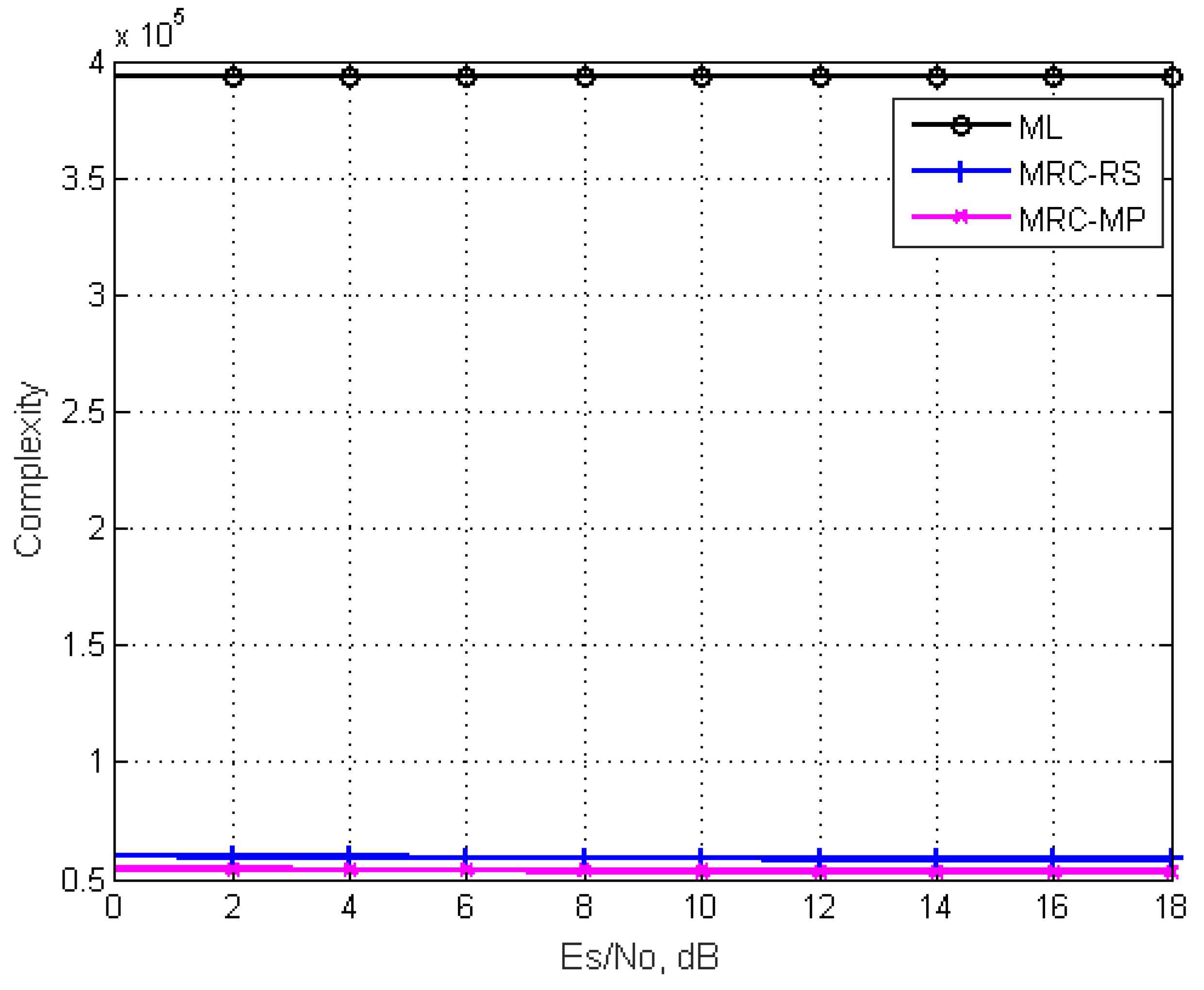
Figure 6 and Figure 7 show the comparison of the computational complexity of the proposed detectors and ML detector in two scenarios: (1) , , , and (2) , , , .
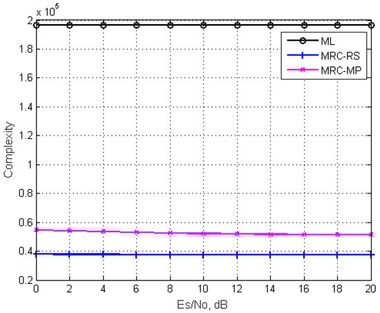
Figure 6.
Comparison of the computational complexity of the proposed detectors and ML detectors for a GSM system with , , and .
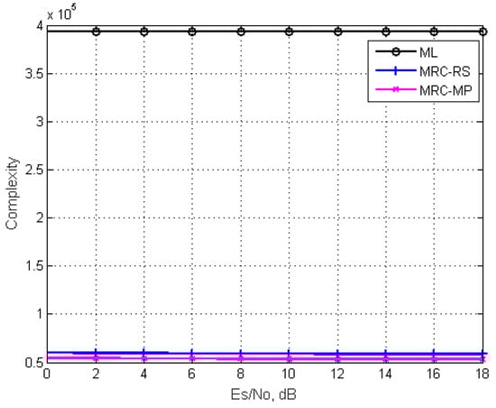
Figure 7.
Comparison of the computational complexity of the proposed detectors and ML detectors for a GSM system with , , and .
It is clear from Figure 6 and Figure 7 that the computational complexity of ML algorithm is the
highest. The computational complexity of MRC-RS and MRC-MP algorithms is
significantly lower than that of the ML algorithm. In addition, the computational
complexity is independent of SNR. In Figure 6,
when SNR is 20 dB, the computational complexity of the MRC-RS algorithm is
37414, which is about 19% of that of the ML algorithm. The computational
complexity of the MRC-MP algorithm is 51284, which is about 26% of that of the ML
algorithm. In Figure 7, when SNR is 18 dB,
the computational complexity of the MRC-RS algorithm is 58481, which is about
15% of that of ML algorithm. The computational complexity of the MRC-MP
algorithm is 53122, which is about 14% of that of the ML algorithm.
5.2. Simulation Result and Computational Complexity Analysis for M-PSK Constellation
5.2.1. Simulation Result
Figure 8 shows the BER performance comparison of the proposed algorithms with the ML algorithm for a GSM system with , , , . From Figure 8,
we can see clearly that the BER performance of the proposed two algorithms is
almost the same as the ML detector.
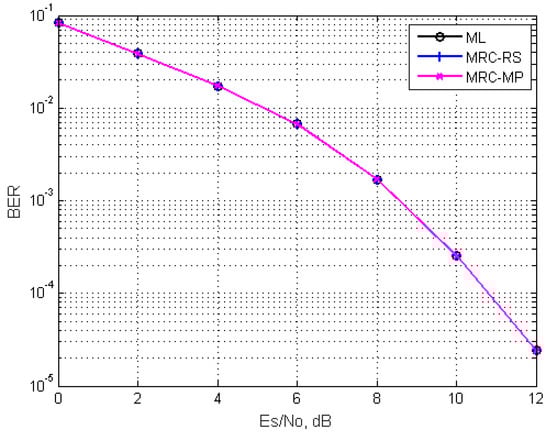
Figure 8.
BER performance comparison of the proposed detectors with ML detector for GSM system with , , and .
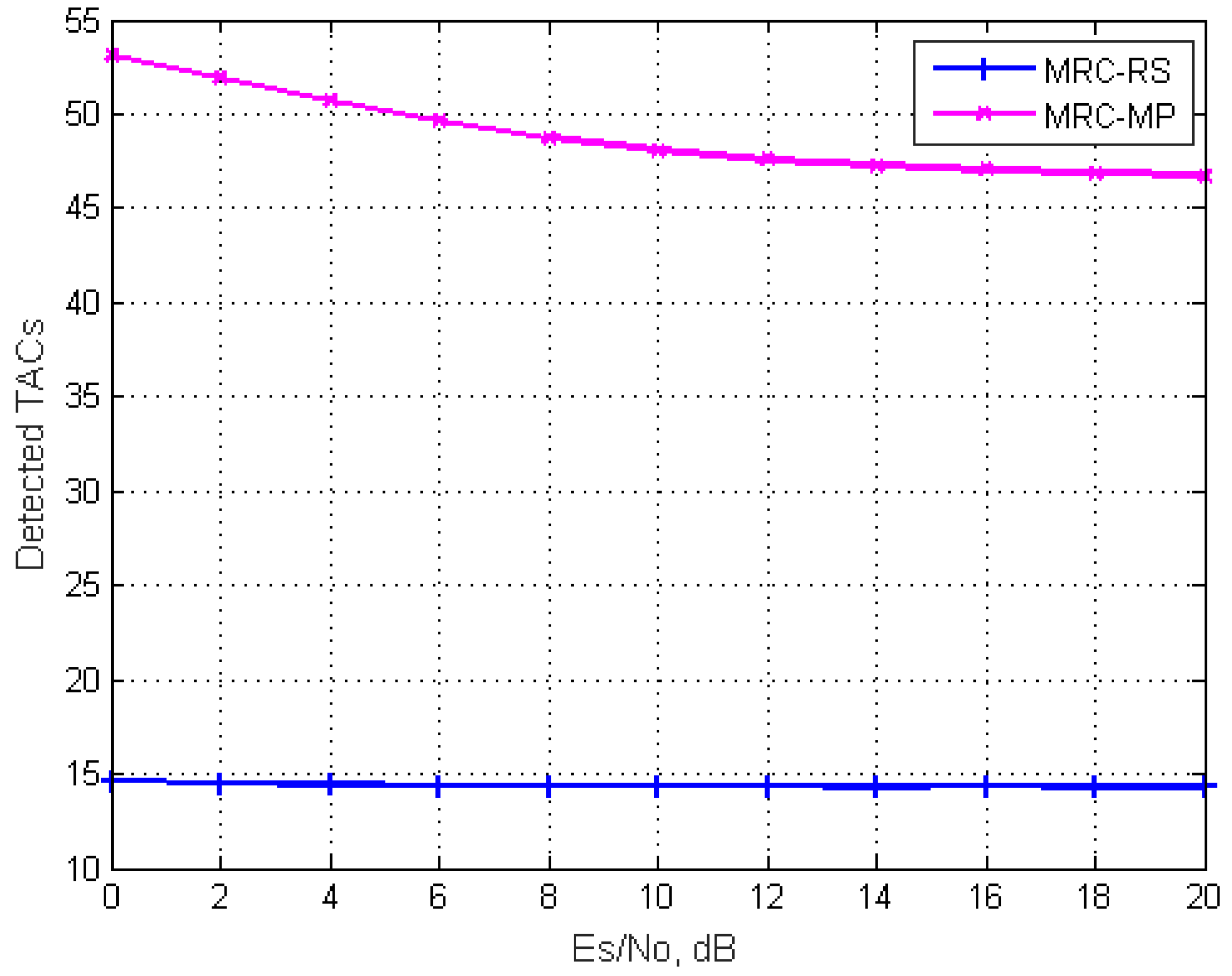
Figure 9 shows the average number of TACs detected by MRC-RS and MRC-MP when , , , . For the conventional GSM system, the total number
of TACs is 64. As can be seen from Figure 9,
the MRC-RS algorithm detects about 14 TACs under different SNR, which accounts
for 21% of the total TACs. For the MRC-MP algorithm, the number of TACs
detected by the receiver shows a downward trend with the increase of SNR. When
SNR is 20 dB, the TACs detected by MRC-MP algorithm is 47, which accounts for
73% of the total TACs.
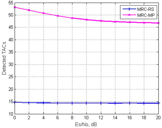
Figure 9.
Average number of TACs finally detected by MRC-RS and MRC-MP detectors when , , and .
5.2.2. Computational Complexity Analysis
Table 4 lists the computational complexity of the above-mentioned three algorithms for the M-PSK constellation.
Table 4.
Comparison of above-mentioned detectors for the M-PSK constellation.
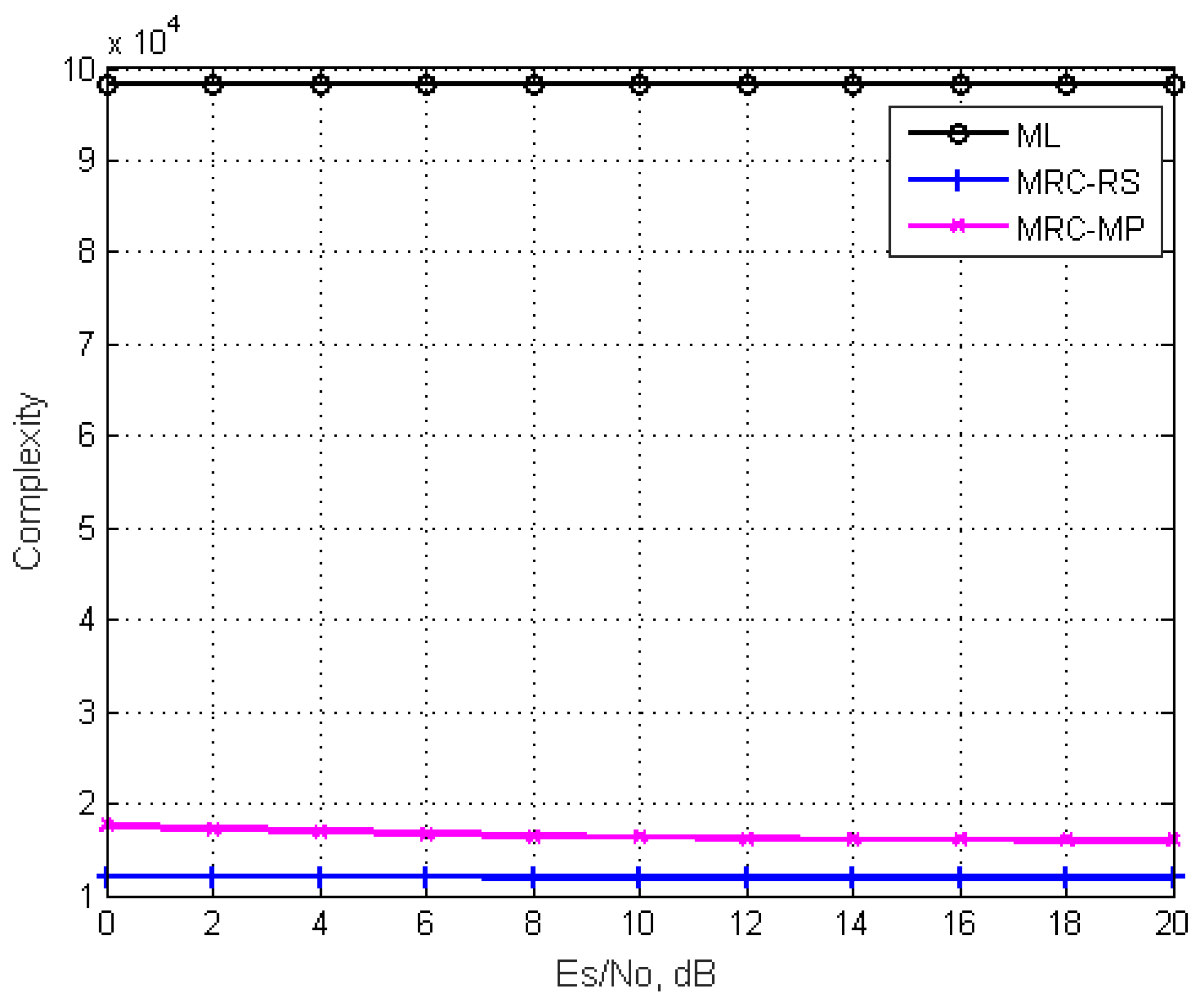
Figure 10 shows the comparison of the computational complexity of the proposed two algorithms with the ML algorithm when , , and . It can be seen that the computational complexity of all three algorithms is almost independent of SNR. Especially when the SNR is 20 dB, the computational complexity of the MRC-RS algorithm is about 11980, which accounts for 12% of the ML algorithm. The computational complexity of the MRC-MP algorithm is about 15975, which is about 16% of the ML algorithm.
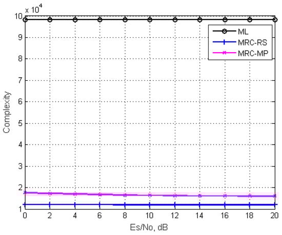
Figure 10.
Comparison of the computational complexity of the proposed detectors and the ML detector for a GSM system with ,
, and .
6. Conclusions
For GSM systems that transmit the same symbols, this paper proposes two suboptimal detection algorithms by reducing the number of TACs detected by the receiver. One is the MRC algorithm based on repeated sorting, which selects the TACs with high probability by sorting twice to improve the detection efficiency at the receiver. The other is the MRC algorithm based on the idea of an OMP strategy, which also reduces the number of TACs through multiple iterations and decreases the computational complexity. The simulation results show that the proposed detection algorithms can achieve almost the same BER performance as ML algorithm, while greatly reducing the computational complexity. For GSM systems with more TACs, it has great significance. Consequent upon the results presented in this paper, our future research will focus on the research on the near-ML detection with lower computational complexity and 5G architecture adaption for future NetApps.
Author Contributions
X.Z. created the main ideas and revised the paper; W.L. wrote the original draft and the program codes; W.L. and H.T. did the simulation experiments. All authors have read and agreed to the published version of the manuscript.
Funding
This research was funded by the Doctoral Scientific Research Foundation of Liaoning Province (Grant No. 2020-BS-225) and the Scientific Research Fund of Liaoning Provincial Education Department of China (Grant No. LJKZ0292).
Data Availability Statement
Not Applicable, the study does not report any data.
Conflicts of Interest
The authors declare that they have no conflict of interest.
References
- Renzo, M.D.; Haas, H.; Ghrayeb, A.; Sugiura, S.; Hanzo, L. Spatial modulation for generalized MIMO: Challenges, opportunities, and implementation. Proc. IEEE 2014, 1, 56–103. [Google Scholar] [CrossRef]
- Renzo, M.D.; Haas, H.; Grant, P.M. Spatial modulation for multiple-antenna wireless system: A survey. IEEE Commun. Mag. 2012, 12, 182–191. [Google Scholar] [CrossRef] [Green Version]
- Chen, C.; Wang, L.; Li, X. A high rate space-time block coding spatial modulation algorithm using constellation rotation. J. Xi’an Jiaotong Univ. 2014, 12, 113–119. [Google Scholar]
- Younis, A.; Serafimovski, N.; Mesleh, R.; Haas, H. Generalised spatial modulation. In Proceedings of the Signals, Systems and Computers Conference: Asilomar Conference Grounds, Pacific Grove, CA, USA, 7–10 November 2010. [Google Scholar]
- Fu, J.; Hou, C.; Xiang, W.; Yan, L.; Hou, Y. Generalised spatial modulation with multiple active transmit antennas. In Proceedings of the IEEE GLOBECOM Workshops, Miami, FL, USA, 6–10 December 2010. [Google Scholar]
- Cal-Braz, J.A.; Sampaio-Neto, R. Low-complexity sphere decoding detectors for generalized spatial modulation systems. IEEE Commun. Lett. 2014, 6, 949–952. [Google Scholar] [CrossRef]
- Jiang, Y.; Lan, Y.; He, S.; Li, J.; Jiang, Z. Improved low-complexity sphere decoding for generalized spatial modulation. IEEE Commun. Lett. 2018, 6, 1164–1167. [Google Scholar] [CrossRef]
- Xiao, Y.; Yang, Z.; Dan, L.; Yang, P.; Yin, L.; Xiang, W. Low complexity signal detection for generalized spatial modulation. IEEE Commun. Lett. 2014, 3, 403–406. [Google Scholar] [CrossRef]
- Chen, F.; Zha, F. Low-complexity signal detection algorithm for generalized spatial modulation. Appl. Res. Comp. 2017, 3, 846–848. [Google Scholar]
- Saad, M.; Lteif, F.C.; Ghouwayel, A.C.A.; Hijazi, H.; Palicot, J.; Bader, F. Generalized spatial modulation in highly correlated channel. In Proceedings of the IEEE International Symposium on Personal Indoor and Mobile Radio Communications (PIMRC), Istanbul, Turkey, 8 September 2019. [Google Scholar]
- Elsayed, M.; Hussein, H.S.; Mohamed, U.S. Fully generalised spatial modulation. In Proceedings of the 35th National Radio Science Conference (NRSC), Cairo, Egypt, 20–22 March 2018. [Google Scholar]
- Guo, S.; Zhang, H.; Zhang, P.; Dang, S.; Liang, C.; Alouini, M. Signal shaping for generalized spatial modulation and generalized quadrature signal modulation. IEEE Trans. Wirel. Commun. 2019, 8, 4047–4059. [Google Scholar] [CrossRef] [Green Version]
- Wu, Y.; Li, M.; Jiang, X.; Bai, E. Low complexity data mapping and detection for jointly mapping generalized spatial modulation. In Proceedings of the 2021 6th International Conference on Communication, Image and Signal Processing (CCISP), Chengdu, China, 19–21 November 2021. [Google Scholar]
- Patachia-Sultanoiu, C.; Bogdan, I.; Suciu, G.; Vulpe, A.; Badita, O.; Rusti, B. Advanced 5G architectures for future NetApps and verticals. In Proceedings of the 2021 IEEE International Black Sea Conference on Communications and Networking (BlackSeaCom), Bucharest, Romania, 24–28 May 2021. [Google Scholar]
- Martian, A.; Craciunescu, R.; Vulpe, A.; Suciu, G.; Fratu, O. Access to RF white spaces in Romania: Present and future. Wirel. Pers. Commun. 2016, 87, 693–712. [Google Scholar] [CrossRef]
- Rajashekar, R.; Hari, K.V.S.; Hanzo, L. Reduced-complexity ML detection and capacity-optimized training for spatial modulation systems. IEEE Trans. Commun. 2014, 1, 112–125. [Google Scholar] [CrossRef]
- Men, H.; Jin, M. Low-complexity optimal MPSK detection for spatial modulation. J. Commun. 2015, 8, 118–124. [Google Scholar]
- Wang, J.; Jia, S.; Song, J. Generalised spatial modulation system with multiple active transmit antennas and low complexity detection scheme. IEEE Trans. Wirel. Commun. 2014, 4, 1605–1615. [Google Scholar] [CrossRef]
Publisher’s Note: MDPI stays neutral with regard to jurisdictional claims in published maps and institutional affiliations. |
© 2022 by the authors. Licensee MDPI, Basel, Switzerland. This article is an open access article distributed under the terms and conditions of the Creative Commons Attribution (CC BY) license (https://creativecommons.org/licenses/by/4.0/).