Abstract
For next generation wireless communication systems, high throughput, low latency, and large user accommodation are popular and important required characteristics. To achieve these requirements for next generation wireless communication systems, an in-band full-duplex (IBFD) communication system is one of the possible candidate technologies. However, to realize IBFD systems, there is an essential problem that there exists a large self-interference (SI) due to the simultaneous signal transmission and reception in the IBFD systems. Therefore, to implement the IBFD system, it is necessary to realize a series of effective SI cancellation processes. In this study, we implemented a prototype of SI cancellation processes with our designed antenna, analog circuit, and digital cancellation function using an adaptive filter. For system implementation, we introduce software-defined radio (SDR) devices in this study. By using SDR devices, which can be customized by users, the evaluations of complicated wireless access systems like IBFD can be realized easily. Besides the validation stage of system practicality, the system development can be more effective by using SDR devices. Therefore, we utilize SDR devices to implement the proposed IBFD system and conduct experiments to evaluate its performance. The results show that the SI cancellation effect can reach nearly 100 dB with order bit error rate (BER) after signal demodulation. From the experiment results, it can be seen obviously that the implemented prototype can effectively cancel the large amount of SI and obtain satisfied digital demodulation results, which validates the effectiveness of the developed system.
1. Introduction
For next generation wireless communication systems, there are some emerging and significant requirements, or key performance indicators (KPI), such as more than five-fold 5G spectral efficiency, less than 1 msec latency, tera-bps level peak data rate, ten-fold 5G network energy efficiency, and so on [1]. To meet the requirements for next generation wireless communication systems, full-duplex (FD) communications, especially an in-band full-duplex (IBFD) communication system is a famous and important candidate technology. Because in a IBFD system the signal transmission and reception are simultaneously processed, essential communication performances such as system spectrum efficiency and transmission latency can be significantly improved, which can meet the core requirements and be provided as one of the attractive candidate technologies for the next generation of wireless communications. In 6G proposals, IBFD is also one of the most popular topics. In [2], the possibilities and challenges for IBFD systems in 6G are investigated and introduced. Because of the advantages of IBFD, it is considered to be applied to work with many possible 6G technologies. For example, non-orthogonal multiple access (NOMA) is one of the key technologies that is usually considered to incorporate with IBFD [3,4].
Therefore, as a possible candidate technology for next generation wireless communication systems, there are many research groups focusing on the realization of FD systems [5,6,7,8,9,10,11,12,13,14], or designing communication techniques for different wireless communication systems based on FD system assumptions [15,16,17,18,19,20,21,22,23,24,25]. For example, in [6], the research group implements a prototype of IBFD system, which is a very famous prototype research of the IBFD system. In [15], the authors design a medium access control (MAC) protocol for the IBFD communications in cognitive radio systems. In [21], the authors provide a non-orthogonal beamforming method with IBFD communications for multiuser (MU) multiple-input multiple-output (MIMO) systems. In [23], the authors investigate secure communications in FD device-to-device (D2D) networks. In [24], the authors adopt FD communications in dual-functional radar systems.
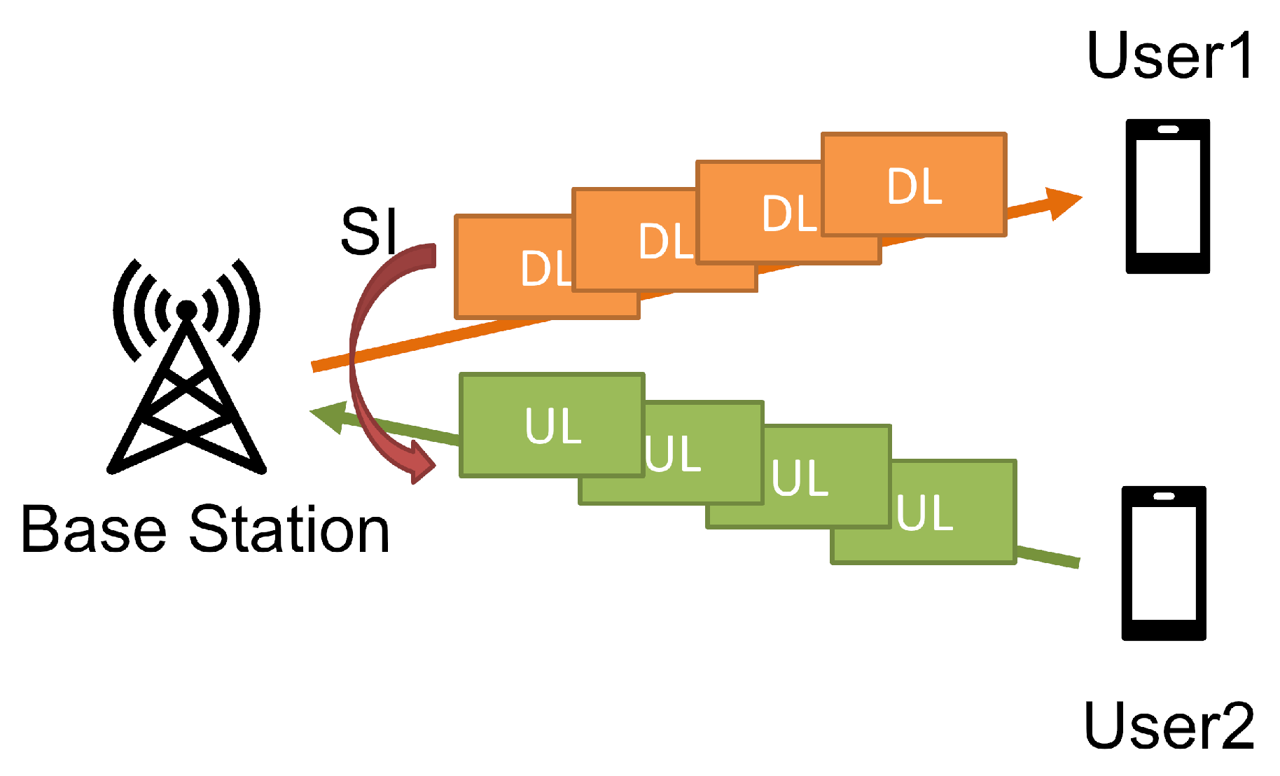
Among the plentiful IBFD-related studies, there is an essential and inevitable self-interference (SI) problem, which must be well handled when implementing IBFD systems. In the IBFD system shown in Figure 1, because the uplink (UL) and downlink (DL) communications happen simultaneously at the base station (BS) in the same frequency band when operating IBFD communications, there will be a severe self-interference problem caused in the system. Due to the huge amount of power difference between UL reception and DL transmission at BS, attenuating or canceling SI in IBFD systems would be a very difficult task. According to the famous pioneer work of IBFD system implementation provided in [6], realizing a basic IBFD system requires a roughly 110 dB SI cancellation effect, which is a very tough and challenging work for wireless communication system implementation.
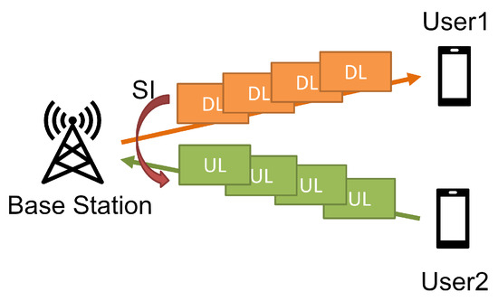
Figure 1.
Basic concept of IBFD system.
However, although SI cancellation is a difficult task to deal with, there are still some inspiring ideas proposed for IBFD system implementations. For example in [5], the authors provide design ideas with SI cancellation effect for IBFD systems. In [8,9,10,11,12,13], the analog circuit (AC) design ideas and implementations for IBFD systems with SI cancellation function are provided. For digital processing of SI cancellation, in [6] the authors investigate the characteristics of the residual SI after the AC part and implement a fixed-type digital filter to handle it. In [25], a method based on game theory is provided to manage interference with imperfect SI cancellation in FD cellular systems. However, because the source of SI comes from the simultaneous DL transmissions at BS, it means the receiving process at BS can obtain the source information of SI, and utilize this information to cancel SI with digital methods [26,27,28,29]. For SI cancellation work, adaptive filter (AF) is a suitable technique to deal with a kind of interference signal with a known interference source.
Due to the simplicity of the computational structure, AF is a famous and useful signal processing technique. AF is usually used for applications like system identifications, inverse system identifications, predictions, and noise or interference cancellations, and so on. When being used for interference cancellation application, AF can significantly cancel the interference by training the known interference source signal to mimic interference signals with moderate computational resources. For example, in [30], the authors utilize analog AF to realize SI cancellation for FD systems. In our previous research [31], we also preliminarily investigated the potential and capability of the AF-based SI cancellation method in a digital way for an IBFD system and the results shows remarkable SI cancellation performance. There are some machine-learning-based methods that can be considered as advanced SI cancellation proposals like [32]. However, for implementation simplicity, in this study we adopt AF as a digital SI cancellation solution.
Therefore, in this study, we extend our previous work in [31] by improving the constituent parts of the system implementation. We realized an IBFD system with improved antenna, analog, and digital processing functionalities. To effectively deal with the severe SI problem of IBFD systems, we carried out a three-stage SI cancellation method in our implementation. Firstly, in our designed antenna part, an antenna isolation effect is provided to suppress SI power. Secondly in AC we designed an adjustable filter circuit to cancel SI in an analog way. In the last stage, we implemented an AF-based SI canceller in the digital processing part to cancel the residual SI after antenna isolation and analog SI cancellation effects. To verify the performance of our implemented IBFD system, we conducted experiments to evaluate the SI cancellation function of each stage, and the final demodulation performance of the whole system. The contributions of this work can be summarized as follows.
- An implementation of an IBFD prototype system is provided in this work. The implemented IBFD system is realized with three-stage SI cancellation, which consists of antenna isolation, analog cancellation, and digital cancellation by adaptive filter.
- By conducting an experimental evaluation, it is known that the implemented three-stage SI cancellation provides a nearly 100 dB SI cancellation effect for the IBFD system implementation.
- With the implemented IBFD system, the resultant bit error rate (BER) can achieve order under a moderate signal-to-noise ratio (SNR), which validates the effectiveness and practicality of our proposed IBFD system implementation design.
The rest of this paper is organized as follows. The system overview is described in Section 2. The SI cancellation method is introduced in Section 3. Experiments are conducted to validate the designed IBFD system in Section 4. Finally, some conclusion remarks are given in Section 5. In addition, all the mathematical notations used in the following sections are summarized in Table 1 for reference.

Table 1.
Mathematical notation list.
2. System Overview
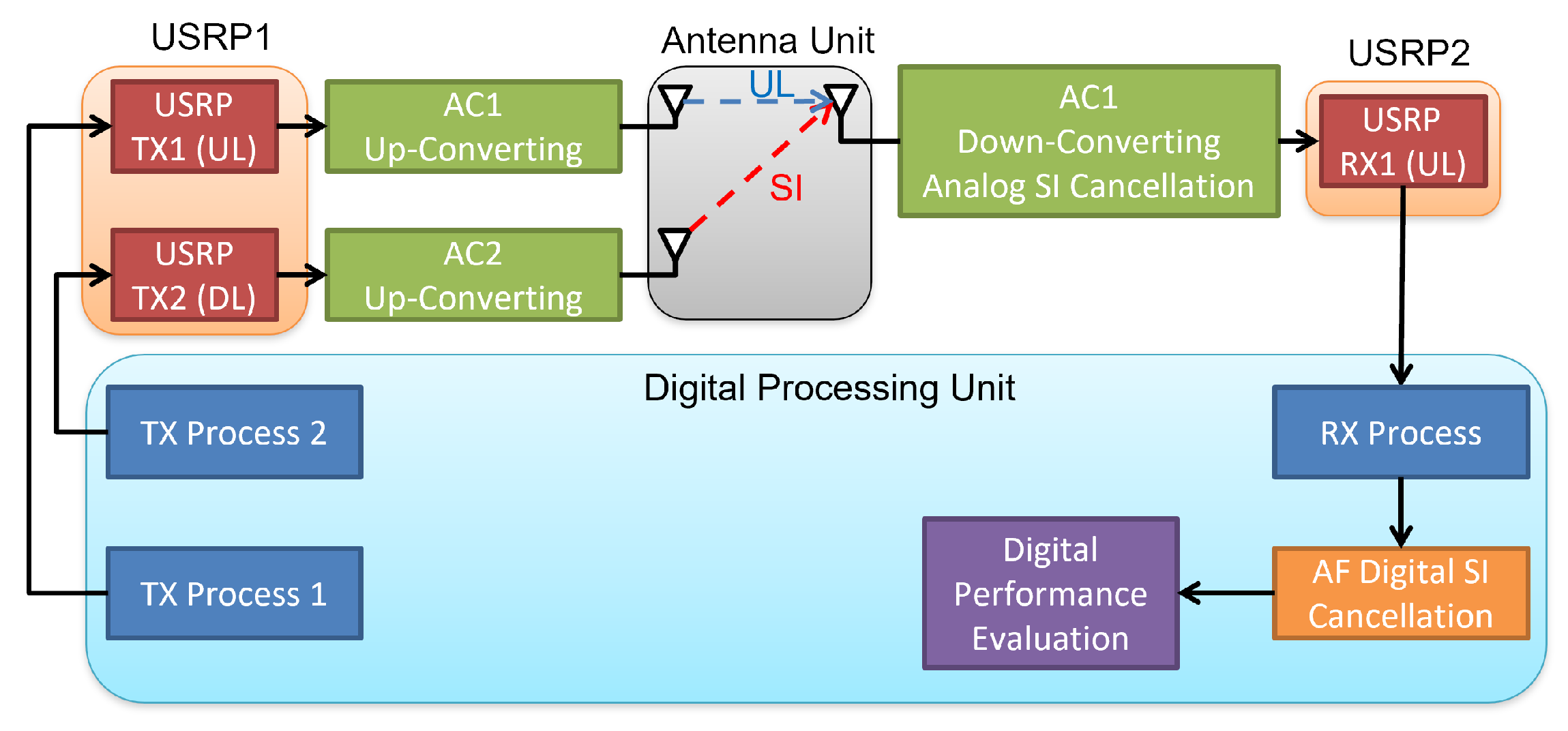
In this study, we implement a basic IBFD system prototype that consists of several constitute parts including an antenna unit, two AC boards, two software defined radio (SDR) devices, and a digital processing unit. The block diagram of the proposed IBFD system implementation is shown in Figure 2. In the following paragraphs, the functionalities of the constitute blocks of the proposed system implementation are introduced with more details.
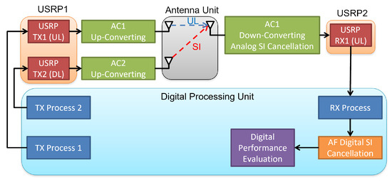
Figure 2.
The block diagram of the implemented system.
Firstly, the digital processing unit is implemented by a high-performance computer with high computational capability. The programming of the digital processing is realized by the MATLAB program platform, which can be connected to the following USRP stage via high-speed ethernet connections. The digital processing unit is responsible for the transmitter (TX) process, receiver (RX) process, SI cancellation with adaptive filter in digital domain, and calculating two performance metrics including error vector magnitude (EVM) and BER of RX signal. The TX process is operating random bit generation, QPSK modulation, and OFDM modulation, while the RX process is processing QPSK and OFDM demodulation. The detailed illustration of the digital SI cancellation using an adaptive filter is provided in Section 3.
The next stage connected to the digital processing unit consists two software-defined radio (SDR) devices responsible for converting digital signals into radio signals. The SDR devices can be customized by users, which makes the evaluations of complicated wireless systems like IBFD easy. Besides for validation of system practicality, the system development can be more effective by using SDR devices. The SDR devices adopted in the proposed system implementation are universal software radio peripheral (USRP) devices. There are two USRP devices included in our implemented system prototype. One serves as a transmitter acting as the desired signal and SI sources. Another one serves as the UL receiver, which receives and processes the combined signal of desired UL signal and SI. The USRP devices adopted in the implemented system prototype are NI USRP 2954R devices, which transmit and receive radio signals at the intermediate frequency (IF) GHz.
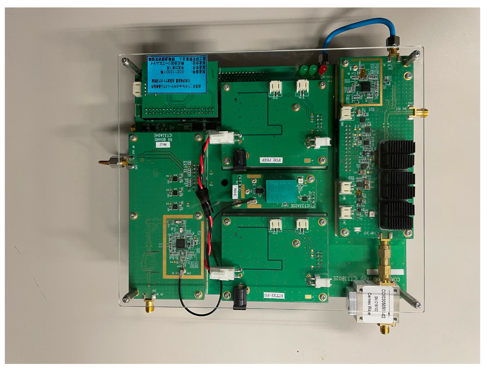
The functional blocks connected to the USRP devices are AC boards, which are responsible for up-converting and down-converting of the operating frequency, Additionally, there is an analog-domain SI cancellation functionality implemented in the AC boards. The up-converting of the operating frequency is shifting the USRP output IF signal with GHz to radio frequency (RF) GHz for the antennas, while the down-converting of the operating frequency is shifting the GHz RF signal from antennas to IF GHz for USRP. In addition to the up-converting and down-converting functionalities, the AC boards are implemented with analog SI cancellation functionality proving about maximum 30 dB analog SI cancellation performance. A photograph of the prototype AC board is provided in Figure 3.
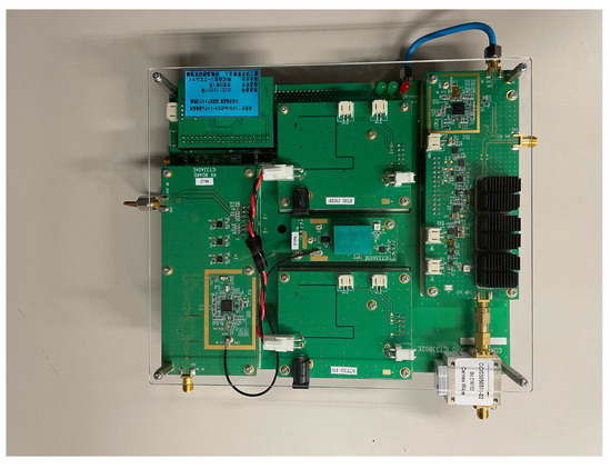
Figure 3.
The designed prototype of analog circuit proposed in [13].
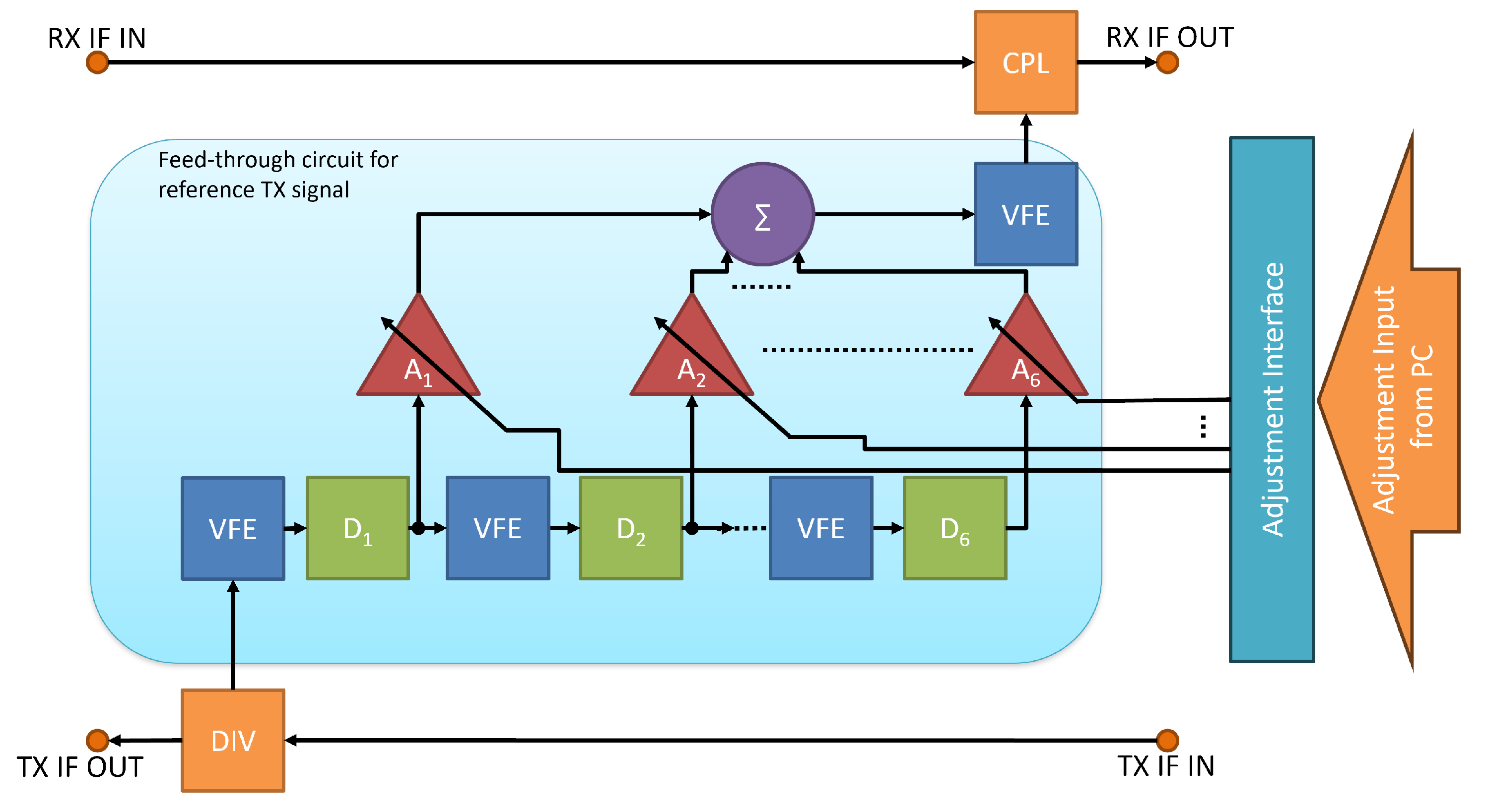
Regarding the SI cancellation functionality realized in AC board, it is carried out by a six-stage multi-tap delay compensation circuit shown in Figure 4. In the designed feedthrough circuit, the delay of the reference TX signal can be adjusted by the combination of the six taps (–), and the phase can be inverted by the phase shifters in each tap. The amplitude of the reference TX signal can be adjusted by the variable gain amplifier (VGA) of each tap (–). The characteristics of the output frequency can be adjusted by the VFEs before each delay component and in the output part. In this prototype, the VFE in the output part is for compensating the frequency characteristics of the SI signal, and VFEs before delay components compensate for the frequency characteristics of each delay component. In this prototype, a six-stage multi-tap delay compensation circuit is applied because 6 taps can sufficiently compensate for the possible SI signal delay caused by RF front-end and TX/RX antennas. In addition, for adjusting the circuit there is an interface that can receive the command from a computer, so that the users can adjust the frequency response of the AC via computer software. The details about AC design can be found in [13]. It is noted that the AC board adopted here can deal with an analog signal with up to 100 MHz bandwidth, which is a very wide band comparing with other former works with several tens of bandwidth like [12].
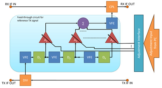
Figure 4.
Block diagram of AC SI canceller.
The last block of the implemented system is an antenna unit, which consists of a pair of identical antennas set as a Tx- and Rx-antenna, respectively. The antenna, as shown Figure 5, is an in-house developed microstrip patch antenna, designed and fabricated on a thin dielectric substrate with a thickness of mm and a relative dielectric constant of 3.3. The microstrip patch antenna is one of the widely used planar antenna in various wireless systems. Figure 6 shows the antenna pair with their parallel (side-by-side) configuration, fabricated on the same dielectric substrate with a fixed distance d (d is defined as the distance between the center of each antenna). This form, integrated TX and RX antennas on the same board, is designed and intended to keep our measurement stable and repeatable, which makes the setup easier and saves the time for measurement as well. The antenna board used in this experiment was one with a distance of 150 mm. Measured results including the return loss of the developed antenna, and the SI between two antennas, denoted as S11 and S21, respectively, are shown in Figure 7. From these results, we can confirm that the antenna has a central operating frequency at GHz, and the SI is about dB at the frequency (i.e., 48 dB isolation, including the loss of the fed-line for each antenna and coaxial adapter for connection to the measurement equipment). The small rips that occurred in the SI response are considered due to the reflection from experimental environment including the surrounded absorber. The antenna measurement was carried out on a network analyzer (PNA Network Analyzer, Model E8361C, 10 MHz 67 GHz, Agilent Technologies) in an anechoic chamber, and completed prior to the system experiment. More detailed information about the antenna design/dimensions, various antenna configurations, measured results of SI between the TX and RX antennas, and thw measurement system can be found in [33], and our other related works.
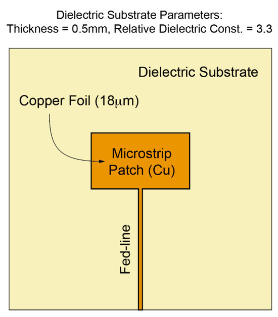
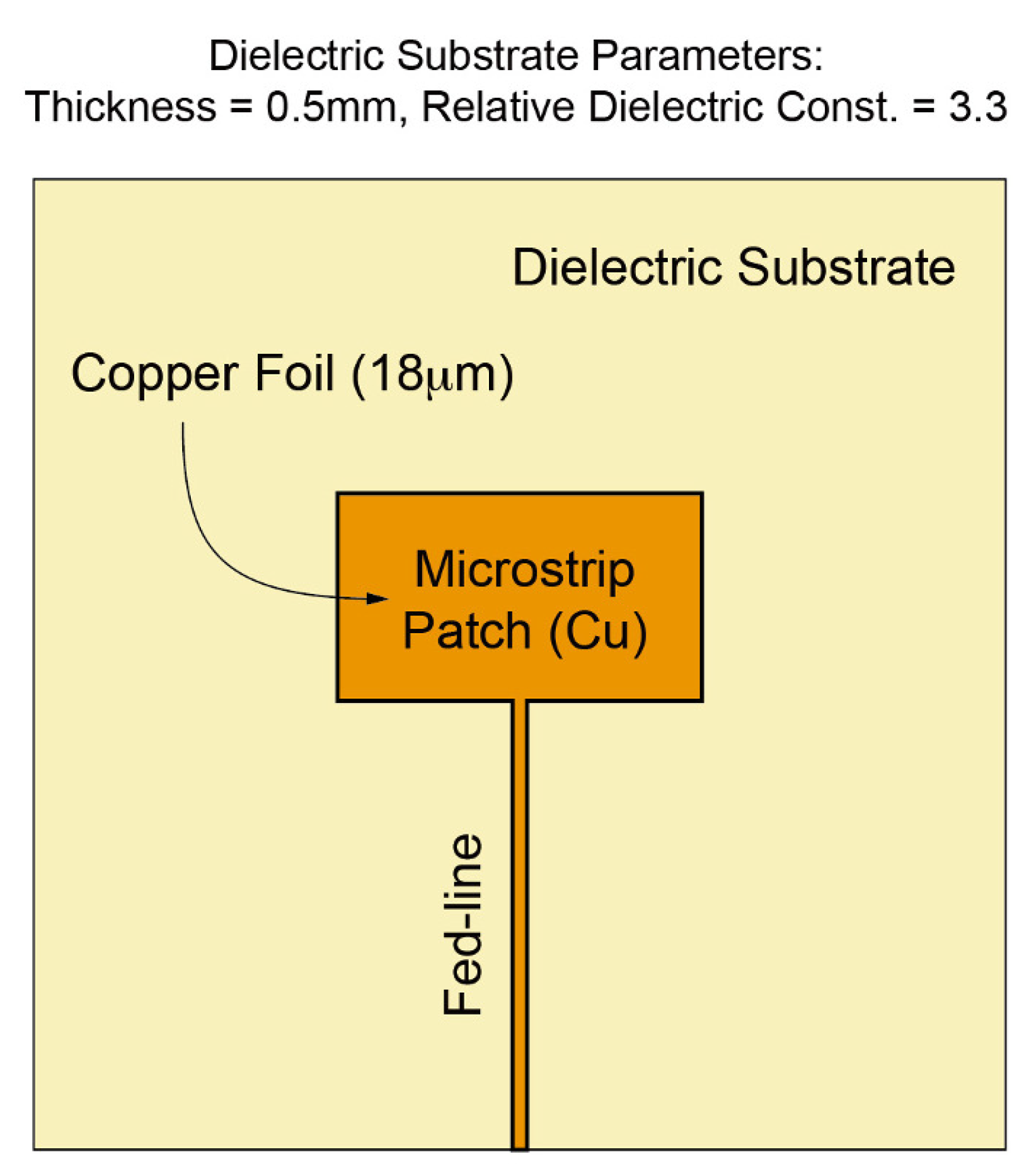
Figure 5.
Planar antenna structure: microstrip patch antenna on a dielectric substrate with thickness of mm, and relative dielectric constant of . The copper foil has thickness of 18 .
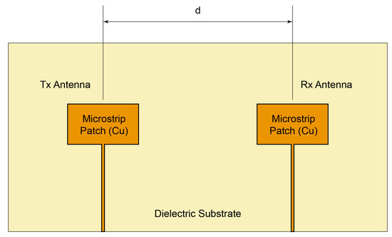
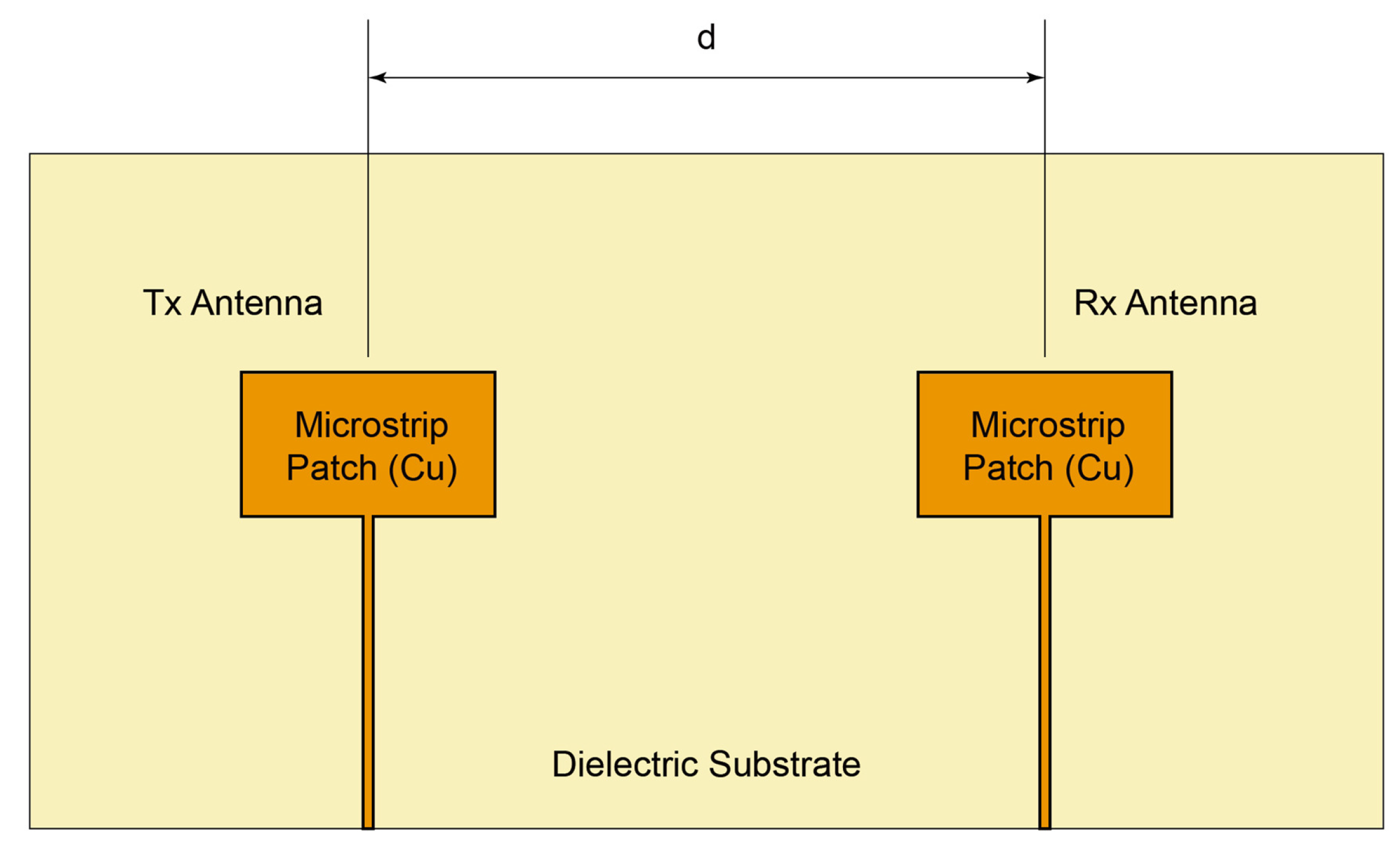
Figure 6.
Parallel (side-by-side) configuration of two antennas (set as TX and RX), integrated on the same substrate with fixed distance (d) between antennas.
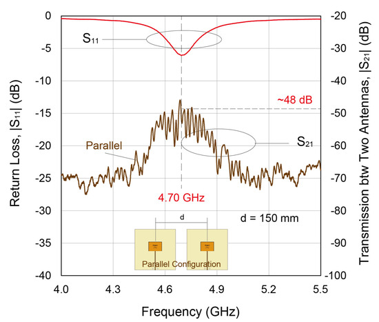
Figure 7.
Measured results of the antennas used in system experiment, return loss (S11) for each antenna, and self-interference (S21) between two antennas. The TX/RX antenna configuration is parallel (side-by-side), distance (d) is 150 mm.
3. Digital SI Cancellation Using Adaptive Filter
In the proposed prototype system, an AF is adopted for the SI cancellation in a digital domain. AF is generally utilized to deal with the interference in a system where a kind of reference signal that is related to the interference signal can be known. In an IBFD system, due to the fact that the SI comes from the DL signals, which can be known at BS, AF is a suitable technology for digital SI cancellation.
The structure of the AF-based SI cancellation method in an IBFD system is provided in Figure 8. The basic structure of the AF-based cancellation method is an -tap adjustable finite impulse response (FIR) filter with -tap delay line and adjustable coefficients. At time index n, the interfered received signal contains two parts: the desired received UL signal and SI signal , i.e., . The SI signal comes from the DL transmitted signal , i.e., , and s is used as a reference signal to be fed into the adjustable FIR filter. The adjustable FIR filter outputs signal as a trained version of , i.e., , where is a vector consists of the adjustable FIR filter coefficients at time index n, which can be expressed as
where represents the adjustable coefficient of the j-th tap of the adjustable FIR filter. Then, the total filter output is obtained from
where is the clean version, i.e., the SI canceled version, of the RX signal. From the description above, the target of the digital SI cancellation is to find best filter coefficients so that , which means that SI is completely canceled in the optimal case . That is, the objective of the digital SI cancellation is to find an optimal filter coefficient vector that
To optimize the optimization problem in (3), firstly, we re-formulate two expressions in the SI cancellation model at time index n in Figure 8 in vector form as
where and represent the vector form of the interfered RX (UL) signal and TX (DL) signal , respectively. Then, the output of the FIR structure of AF, i.e., , can be expressed as
where means the trained version of the SI source . Then, the AF SI cancellation can be operated by subtracting the result of (6) from the interfered RX signal as in (2).
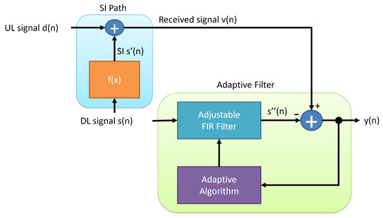
Figure 8.
SI cancellation by adaptive filter.
From the expression in (2), it can be known that the AF output is actually the difference between RX signal and FIR output , and can be reformulated as
Because the UL-desired signal is uncorrelated to either or , solving the optimization problem in (3) is equivalent to the minimization of (7). To minimize (7), the mean square error (MSE) of the AF can be derived from the expression in (2) as
where , , and (9) is from (6).
By solving , the optimal filter coefficient vector can be obtained as [34]
However, the optimal filter coefficient vector in (11) is difficult to calculate in real-time and is inapplicable in practical implementation. Therefore, here we introduce a least mean square (LMS)-based algorithm [34] to iteratively approach the optimal solution . For LMS, instead of finding the optimal solution directly, the algorithm keeps approaching the optimal solution iteratively. Hence, instead of the MSE expression in (8), the instantaneous expression of the square error is used to find the deepest descent towards the optimal solution as
where (13) is from (9). The AF is then able to approach the optimal solution with the deepest descent in (14) in an iteratively updated filter coefficient vector form as
where is the step-size value that controls the speed of the AF algorithm along the deepest descent towards the optimal solution.
However, the convergence issue is a very essential topic when using the LMS method. The whole AF output may diverge if the step-size does not satisfy the following condition:
which means the value of the step-size should be small enough comparing with the power of the input signal so that the LMS method can trace the optimal solution in a convergent way. To ensure the convergence of the AF, here we adopt a variation of LMS method, which is called normalized least mean square (nLMS) method [34] in our implementation. The nLMS method uses a modified step-size , which is normalized to the power of the input vector and can be expressed as
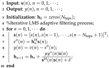
where is a small positive number to ensure that the algorithm can avoid the singularity that . The nLMS algorithm is listed in Algorithm 1.
From the expressions of the algorithm, it can be known that the realization of the nLMS algorithm needs multiplications, additions, and 1 division operation. Because the operations of nLMS algorithm do not involve matrix operations, its computational complexity is [35].
In addition, to analyze the optimality of the nLMS algorithm, it is necessary to investigate its steady-state conditions. The steady-state conditions of the nLMS algorithm can be analyzed by the misalignment norm method [36], which is briefly introduced as follows.
First of all, the misalignment can be defined as
where is the optimal filter weighting vector, which can minimize the MSE of AF. By taking expectation on the square norm of time difference of (18), the following expression can be obtained:
where equals in the LMS case and equals in (17) in the nLMS case. In steady-state, the difference expression (19) should be 0, which results in the steady-state MSE of LMS as
where and is the background noise power. The function can be expressed as
where and . The upper bound of the convergence time of the LMS algorithm is
where is the maximum value of , is a given excess noise power, and .
For nLMS, by similar derivations, the steady-state MSE can be expressed as
where
and
with and . The upper bound of the convergence time of the nLMS algorithm is then
where is the minimum value of . By analyzing the steady-state MSE and convergence time of LMS and nLMS algorithms, nLMS can reach a lower steady-state MSE within a smaller convergence time. The details about the analysis for the LMS and nLMS algorithms can be found in [36].
| Algorithm 1: nLMS adaptive filter algorithm. |
 |
4. Experimental Evaluation
In this section, we conduct experiments to verify the practicality of our proposed IBFD system prototype, which is introduced in Section 2. Here, we firstly investigate and validate the SI cancellation performance, and then evaluate the whole system performance of the proposed system. The experiments were carried out with the proposed system implementation mentioned in Section 2 in a NICT anechoic chamber in Yokosuka, Kanagawa, Japan. A picture of the experimental scene in the NICT anechoic chamber is shown in Figure 9. In the conducted experiments, in order to evaluate the SI cancellation performance of the antenna and AC board, in addition to the devices described in Section 2, a spectrum analyzer is used to measure the signal power of antenna and AC boards, as shown in Figure 9. Additionally, the system experimental parameters are summarized in Table 2. It is noted that in this experiment we only use a single carrier to transmit data with OFDM modulation. Additionally, in this work, we focus on implementing a basic IBFD system prototype to investigate and show the possibilities of it, so that we choose the system parameters based on the criterion of maximizing the system performance considering the capabilities of the instruments and devices employed. The experiments are conducted by the following steps:
- Step 1: Turn on SI signal;
- Step 2: Evaluate SI cancellation of antenna;
- Step 3: Evaluate SI cancellation of AC;
- Step 4: Turn on desired signal and combine desired signal with SI;
- Step 5: Evaluate constellations, EVMs, and BERs before and after turning on AF-based digital SI cancellation.
The results of the conducted experiments are given and discussed in the following subsections.
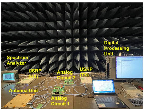
Figure 9.
Experiment settings.
Figure 9.
Experiment settings.
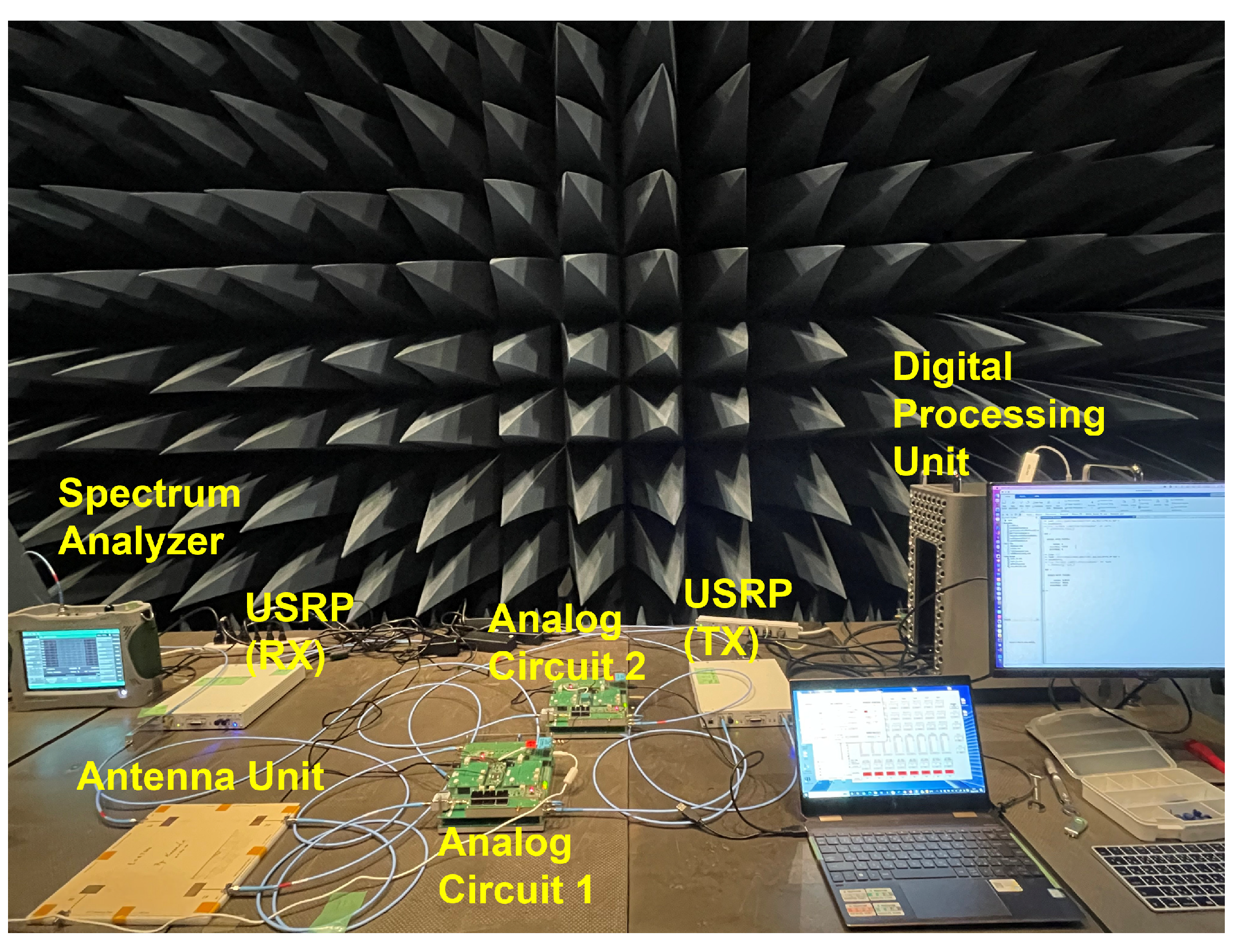
Table 2.
System parameters for experiments.
Table 2.
System parameters for experiments.
| Parameter | Value |
|---|---|
| USRP Operating Frequency | GHz |
| RF Operating Frequency | GHz |
| Signal Bandwidth | 16 MHz |
| Antenna Spacing | 15 cm |
| Modulation | QPSK |
| OFDM FFT Size | 256 |
| Operating SNR | 10–25 dB, with dB interval |
| AF FIR Taps | 20 |
| Step-size |
4.1. Antenna SI Cancellation
The SI cancellation performance, which resulted from antenna isolation, is evaluated by the spectrum analyzer and the results are shown in Figure 10. From the values shown in Figure 10, it can be observed that the noise floor is around dBm. Additionally, the marker 3 in Figure 10 marks the SI power before the antenna, while marker 2 marks the SI signal power after antenna isolation. The value measured by marker 3 is dBm, while the value marked by marker 2 is dBm. From the results shown in Figure 10, it can be observed that the SI signal power after the antenna is attenuated by dB, which significantly validates the SI cancellation performance of antenna isolation.
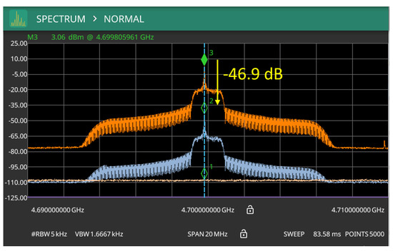
Figure 10.
Antenna SI isolation result.
4.2. SI Cancellation by Analog Circuit
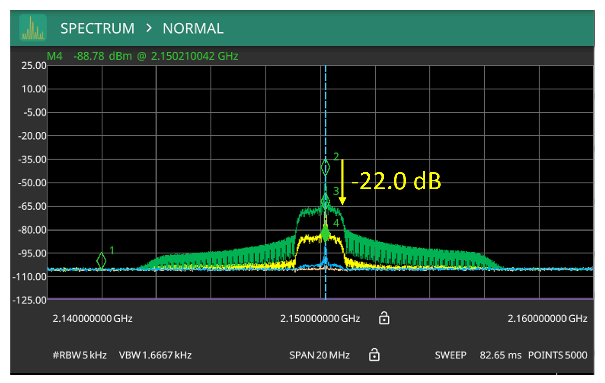
The spectrum analyzer was also utilized to evaluate the performance of the SI cancellation performance of the proposed AC prototype. The results are shown in Figure 11. From the values shown in Figure 11, it can be observed that the noise floor is also around dBm. Additionally, the marker 2 in Figure 11 marks the SI power before AC, while marker 3 marks the SI signal power after analog SI cancellation in AC. After about dB power loss due to cables and connectors between antenna and AC board, the value measured by marker 2 is dBm, while the value marked by marker 3 is dBm. From the results, its can be known that the AC can suppress SI signal power by dB. The experimental results indicate that a substantial attenuation of the SI power can be provided by the SI cancellation functionality in the AC board, which validates the effectiveness of the AC prototype design.
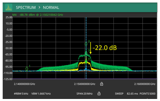
Figure 11.
SI cancellation result by analog circuit.
4.3. SI Cancellation by Adaptive Filter
Instead of using the spectrum analyzer to evaluate the SI cancellation performance of the antenna and AC board, the AF-based digital SI cancellation performance is evaluated in some digital ways. Specifically, the performance of the digital part is evaluated by investigating the constellation plot, EVM, and BER of the whole system. The evaluated results of the digital part are provided and addressed in the following paragraphs.
4.3.1. Constellation Plot
To illustrate the performance of the AF-based digital SI cancellation, here we present constellation plots for the RX signal before and after SI cancellation with a SNR of 25 dB as examples in Figure 12 and Figure 13, respectively.

Figure 12.
Constellation before AF processing.
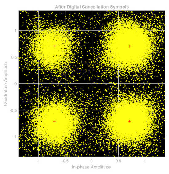
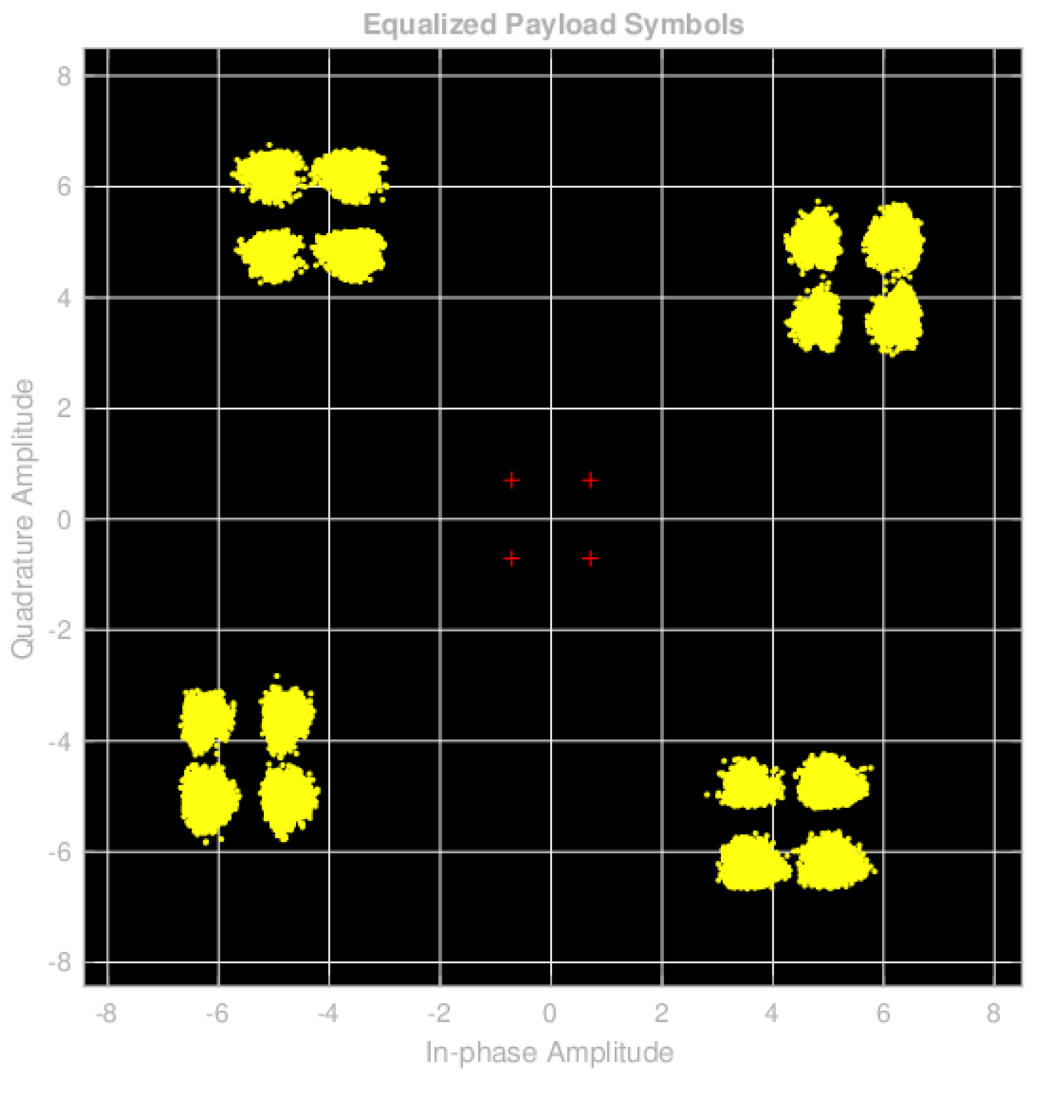
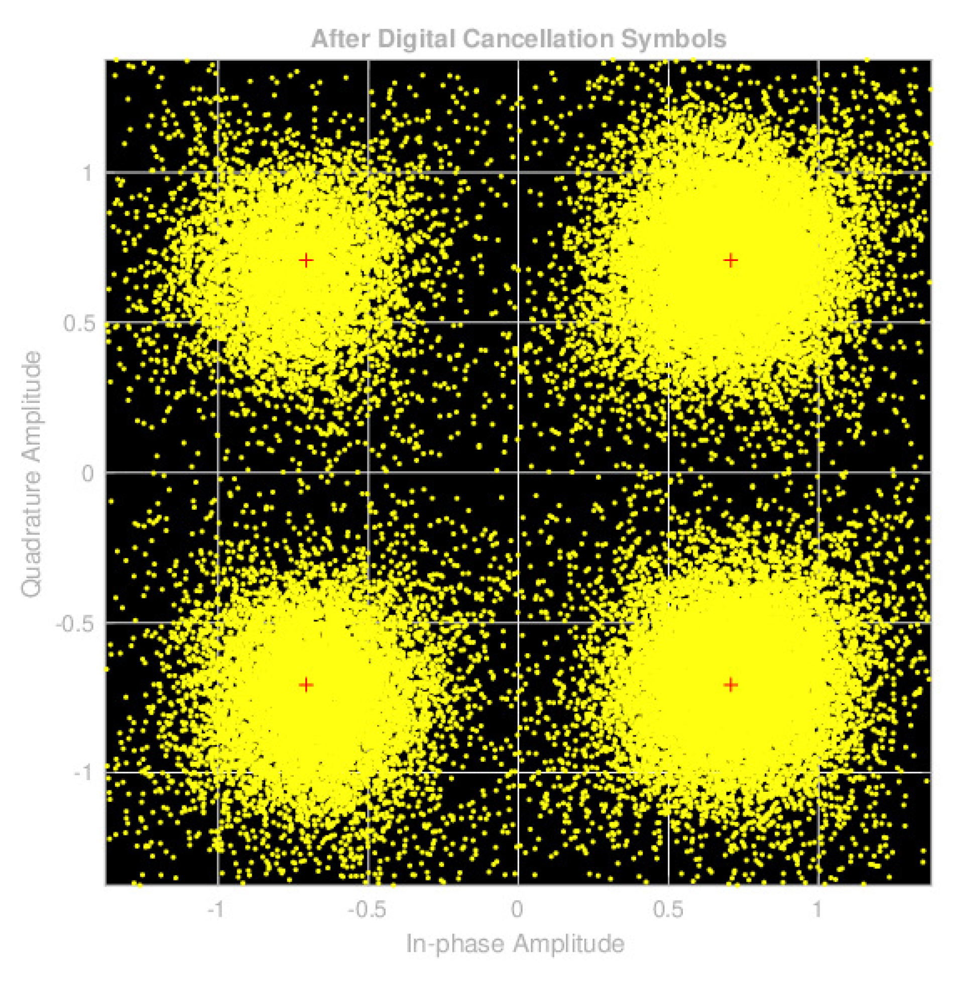
Figure 13.
Constellation after AF processing.
In Figure 12, the QPSK constellation points of the desired UL signal are denoted by red crosses, while the yellow points represent the constellation points of the RX signal containing both UL and SI signals. Conversely, in Figure 13, the red crosses represent the QPSK constellation points of the desired UL signal, and the yellow points represent the signal constellation points after undergoing essential signal synchronization and SI cancellation using AF.
Analysis of the results in Figure 12 reveals a significant contamination of the desired UL signal by SI, which causes the constellation points to deviate significantly from their original positions (the locations of the red cross marks). This distortion makes it nearly impossible to recover the information carried by the UL signals.
Conversely, examination of the results in Figure 13 demonstrates that, following necessary processing such as signal synchronization and AF-based SI cancellation, the impact of SI is substantially mitigated. As a result, the constellation points are restored to the vicinity of the desired signal’s positions, offering a more favorable prospect for the system to recover information from the processed signal.
4.3.2. EVM Evaluation
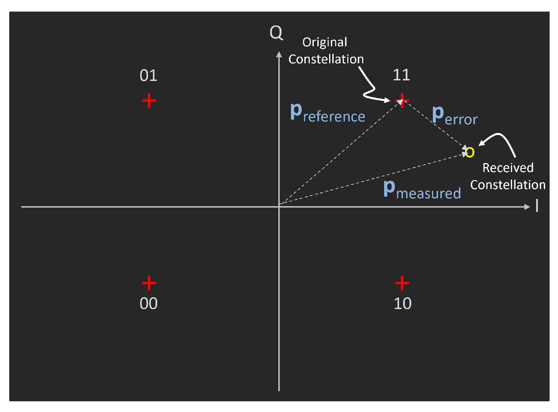
To precisely quantify the enhancement by AF-based SI cancellation on the RX UL signal, we introduce the EVM method as a measure of assessing constellation points. The fundamental concept of EVM is illustrated in Figure 14. Essentially, the EVM method quantifies how much the signal deviates from its expected position, providing a quantitative measure of digital signal processing performance.

Figure 14.
Definition of EVM evaluation.
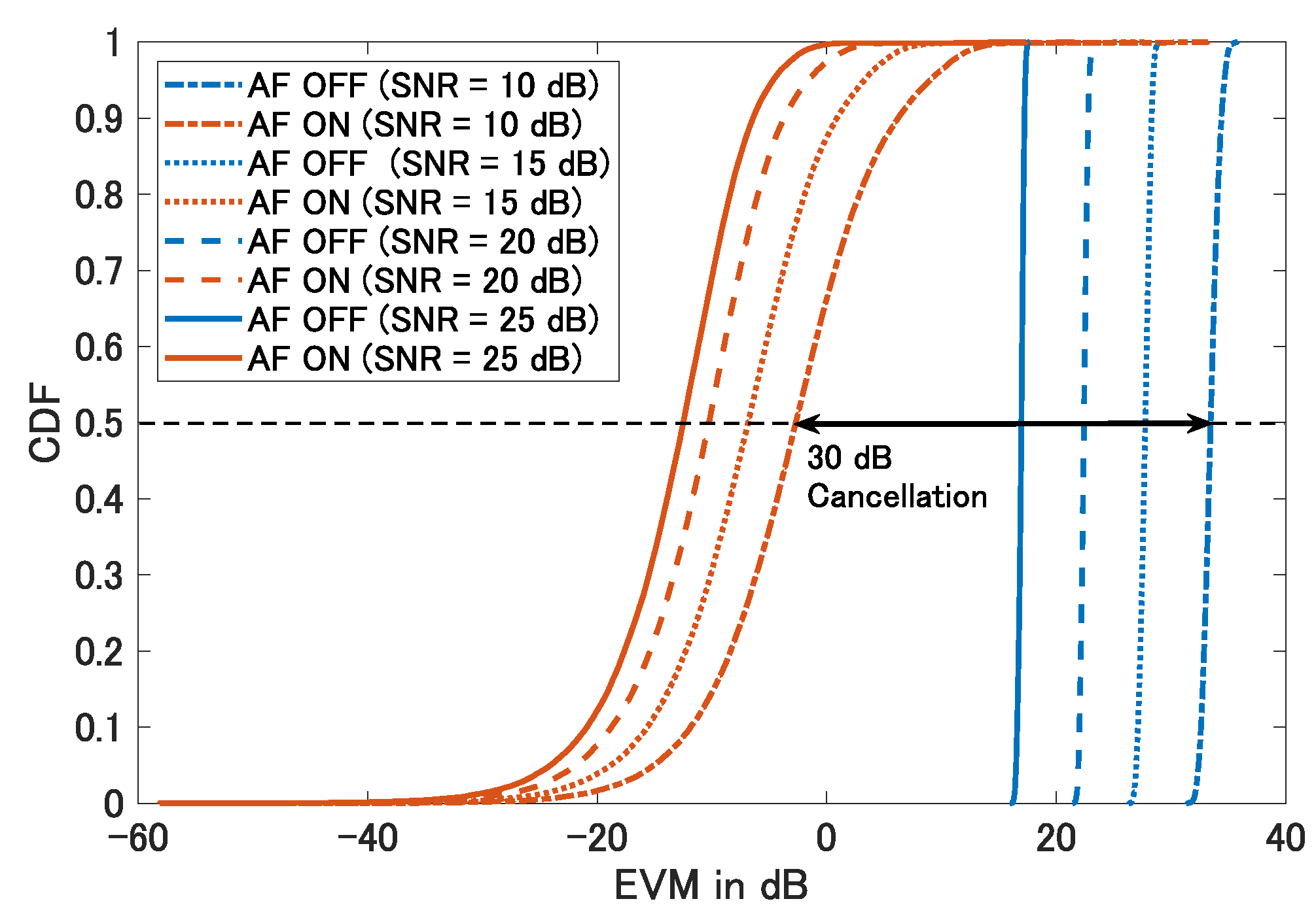
For instance, in Figure 14, the TX signal constellation is represented by the red cross marked with the code ‘11’. The cumulative distribution function (CDF) curves of the RX signals are presented in Figure 15. In this figure, the red and blue curves correspond to results obtained with and without AF-based SI cancellation, respectively. Furthermore, the solid, dashed, and dotted curves are examples depicting signal performance at SNRs of 10, 15, 20, and 25 dB.
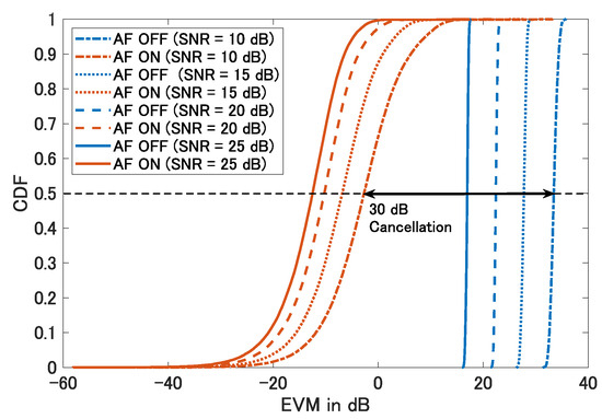
Figure 15.
CDF of the EVM results.
Analysis of the CDF results in Figure 15 reveals that at the CDF point, which roughly signifies the average position within a distribution, the EVM assessment indicates an improvement of approximately 30 dB in signal constellations when employing AF-based SI cancellation.
4.3.3. BER Evaluation
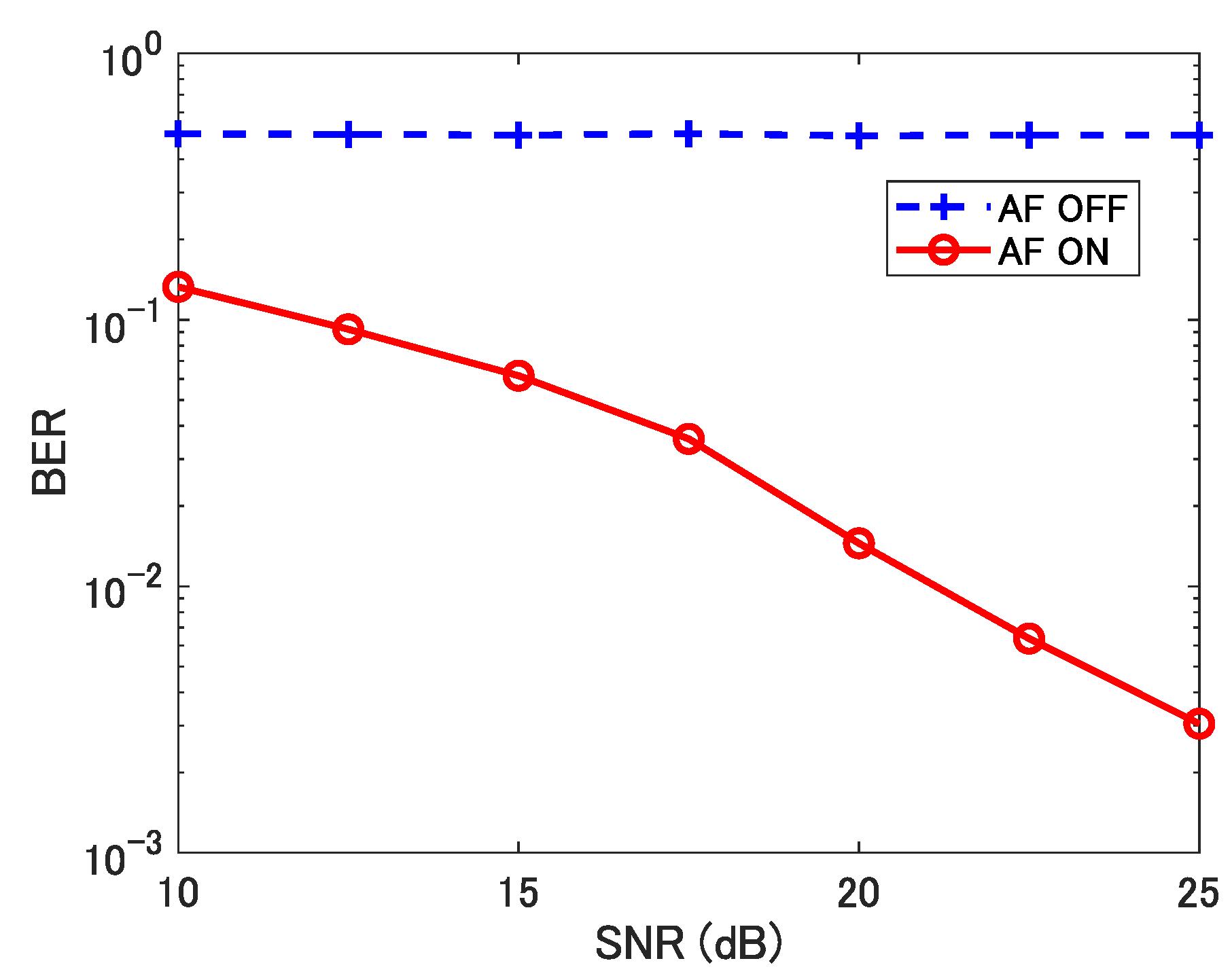
Finally, to provide a comprehensive assessment of the overall performance of the proposed IBFD system, we examine the BER derived from the RX UL signals. The BER curve for the proposed IBFD system is depicted in Figure 16. A close examination of the results in Figure 16 reveals that the BER reaches the order of when the SNR exceeds approximately 22 dB. This achievement aligns with the initial usability requirements of a wireless system.
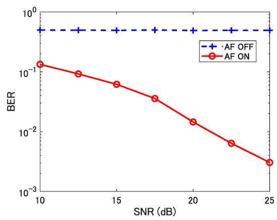
Figure 16.
BER results.
As previously mentioned, the proposed system prototype incorporates a three-stage SI cancellation method, totally achieving about 100 dB of SI cancellation performance. This AF-based SI cancellation process results in a synthesized outcome capable of achieving a BER in the order of under reasonable SNR conditions, which significantly validates the effectiveness and practicality of the proposed system design.
4.4. Discussion
In the subsections above, we show the SI cancellation performance of each stage of our IBFD prototype implementation. The experimental evaluated results of the SI cancellation are summarized and listed in Table 3. Besides the results obtained from the experiments in this study, we also listed some benchmark works in Table 3. Here, we list the implementation works of IBFD systems in [5,6], together with our previous work [31] for comparison. In [5], the authors also implemented an IBFD system with an antenna, RF front-end analog SI cancellation, and digital SI cancellation. In [6], the authors implemented an IBFD system using a signal generator as TX and a spectrum analyzer as RX. Between TX and RX they designed and realized a two-stage SI cancellation method consisting of analog and digital cancellation.
Table 3.
Summary of IBFD implementation proposals.
Comparing the SI cancellation in the antenna stage, in [5] the TX and RX antennas are placed with half-wavelength distances so that the TX and RX signals can be orthogonal, which provides a 20 dB antenna SI cancellation effect. However, the performance of this method is essentially affected by the signal frequency and cannot be applied in wide band systems. On the other hand, the antenna designs in [31] and this study are targeting at more than 100 MHz wide band signals and provide around 31 dB and 47 dB Si cancellation effects, respectively. About the performance of the ACs, although the proposal in [5] adopts a circuit available on the market but in [31] a self-designed feed through circuit is used, they both provide about 30 dB analog SI cancellation performance. In [6], only analog SI cancellation is realized with a sinc interpolation algorithm, which results in a total 62 dB SI cancellation performance. In this study, although the AC provides merely 22 dB SI cancellation performance, but its frequency response is more stable and balanced than the proposal in [31].
In addition, although the proposal in [6] only realizes SI cancellation in analog and digital parts, we can still exam the performance at the analog output for a comparison. The SI cancellation results at the analog output, i.e., SI cancellation of “Antenna + Analog”, are also listed in Table 3. From the results of “Antenna + Analog” it can be seen that the proposals in [6,31] are both capable of providing about 60 dB SI cancellation at the output of analog stage, but the proposal in [5] can provide only about 50 dB. However, the proposed scheme in this study can provide about 70 dB SI cancellation performance, which outperforms all other proposals.
In the digital part, the proposal in [5] applies coherent detection to detect the received signal and then suppresses the SI component that is known at the BS side. This is a straightforward way that can provide 10 dB SI cancellation performance. In our previous work [31], the AF-based digital SI cancellation provides dB SI reduction, and in this study the digital part can provide dB SI cancellation performance because of better signal-to-interference-plus-noise radio (SINR) of the received signal due to better analog and digital front-end processing. In [6], the authors carefully analyzed the linear and non-linear parts of the residual signal from the analog part, and then designed a special digital filter to cancel the residual SI from the analog part, which results in an impressive dB SI cancellation performance. However, the digital solution in [6] is a static way that is hard to deal with in dynamic channels. On the other hand, our AF-based proposal provides a solution that can process signals in changing channels.
It is noted that there are some related issues that can be extended for this study. Firstly, although in this study only QPSK is implemented, higher order modulations can also be applied under the infrastructure provided in this study, and their performance can be inferred by the SINR variations revealed in [6]. Secondly, adopting NOMA technologies with IBFD is an emerging and popular issue for 6G communications. For example, using IBFD in NOMA relaying [3] or cooperative NOMA systems [4] are proposed to essentially improve system performance. In these NOMA scenarios, the proposal in this study can also be applied because the SI source information is known at the receiver, and the detail analysis and implementations are left as our future works.
5. Conclusions
In this study, we have realized a fundamental prototype of an IBFD wireless communication system with a three-stage SI cancellation including antenna, analog, and digital processing functionalities. Notably, within the digital processing domain, we adopt FIR-type AF-based SI cancellation with the LMS adaptive algorithm, which is a computationally efficient and readily implementable AF technique.
To verify the performance of our proposed IBFD prototype system, we conducted a series of experiments. The experimental findings reveal that the antenna isolation and SI cancellation components in AC can effectively suppress SI power by an impressive about 30 dB each. Furthermore, upon assessing the EVM and BER of the demodulated signal following the application of AF-based digital SI cancellation, it becomes evident that this digital SI cancellation methodology also delivers a substantial 30 dB SI cancellation performance boost.
Furthermore, these results show the remarkable effectiveness of our proposed IBFD system, by its capacity to attain a BER in the order of when the SNR is larger than 22 dB, which significantly validates the effectiveness and practicality of the proposed IBFD system design.
The proposed system implementation prototype is a universal proposal that can be applied in most wireless systems like cellular systems. In the future, we are planning to implement the proposal in this study on the 5G New Radio (5GNR) platform as our next step.
Author Contributions
Conceptualization, W.-S.L.; methodology, W.-S.L., O.Z., K.L. and T.M.; software, W.-S.L. and O.Z.; validation, W.-S.L., O.Z., K.L. and T.M.; formal analysis, W.-S.L. and O.Z.; investigation, W.-S.L. and O.Z.; data curation, W.-S.L.; writing—original draft, W.-S.L.; writing—review and editing, W.-S.L., O.Z., K.L., H.K. and T.M.; visualization, W.-S.L.; supervision, T.M.; project administration, H.K. and T.M.; funding acquisition, T.M. All authors have read and agreed to the published version of the manuscript.
Funding
A part of this research has been conducted under the contract “R&D for the realization of high-precision radio wave emulator in cyberspace” (JPJ000254) made with the Ministry of Internal Affairs and Communications of Japan.
Data Availability Statement
Not applicable.
Conflicts of Interest
The authors declare no conflict of interest.
Abbreviations
The following abbreviations are used in this manuscript:
| Adaptive Filter | AF |
| Analog Circuit | AC |
| Base Station | BS |
| Bit Error Rate | BER |
| Coupler | CPL |
| Device-to-Device | D2D |
| Divider | DIV |
| Downlink | DL |
| Error Vector Magnitude | EVM |
| Fixed Impulse Response | FIR |
| Full-duplex | FD |
| In-band Full-duplex | IBFD |
| Inout-output | I/O |
| Intermediate Frequency | IF |
| Key Performance Indicator | KPI |
| Least Mean Square | LMS |
| Mean Square Error | MSE |
| Medium Access Control | MAC |
| Multiple-input Multiple-output | MIMO |
| Multiuser | MU |
| Non-orthogonal Multiple Access | NOMA |
| Normalized Least Mean Square | nLMS |
| Not Available | NA |
| Orthogonal Frequency Division Multiplexing | OFDM |
| Radio Frequency | RF |
| Receiver | RX |
| Self-interference | SI |
| Signal-to-interference-plus-noise Radio | SINR |
| Signal-to-noise Radio | SNR |
| Software Defined Radio | SDR |
| Successive Interference Cancellation | SIC |
| Transmitter | TX |
| Universal Software Radio Peripheral | USRP |
| Uplink | UL |
| Variable Frequency Equalizer | VFE |
References
- Akhtar, M.W.; Hassan, S.A.; Ghaffar, R.; Jung, H.; Garg, S.; Hossain, M.S. The shift to 6G communications: Vision and requirements. Hum. Cent. Comput. Inf. Sci. 2020, 10, 53. [Google Scholar] [CrossRef]
- Smida, B.; Sabharwal, A.; Fodor, G.; Alexandropoulos, G.C.; Suraweera, H.A.; Chae, C.-B. Full-duplex wireless for 6G: Progress brings new opportunities and challenges. IEEE J. Sel. Areas Commun. 2022, 41, 2729–2750. [Google Scholar] [CrossRef]
- Amin, A.A.; Shin, S.Y. Capacity analysis of cooperative NOMA-OAM-MIMO based full-duplex relaying for 6G. IEEE Wirel. Commun. Lett. 2021, 10, 1395–1399. [Google Scholar] [CrossRef]
- Elhattab, M.; Arfaoui, M.A.; Assi, C.; Ghrayeb, A. Reconfigurable intelligent surface enabled full-duplex/half-duplex cooperative non-orthogonal multiple access. IEEE Trans. Wirel. Commun. 2022, 21, 3349–3364. [Google Scholar] [CrossRef]
- Choi, J.I.; Jain, M.; Srinivasan, K.; Levis, P.; Katti, S. Achieving single channel, full duplex wireless communication. In Proceedings of the Annual International Conference on Mobile Computing and Networking, Chicago, IL, USA, 20–24 September 2010; pp. 1–12. [Google Scholar]
- Bharadia, D.; McMilin, E.; Katti, S. Full duplex radios. In Proceedings of the Annual Conference of the ACM Special Interest Group on Data Communication (SIGCOMM), Hong Kong, China, 12–16 August 2013; pp. 375–386. [Google Scholar]
- Tong, Z.; Russ, C.; Vanka, S.; Haenggi, M. Prototype of virtual full duplex via rapid on-off-division duplex. IEEE Trans. Commun. 2015, 63, 3829–3841. [Google Scholar] [CrossRef]
- Narieda, S. Dual stage analog cancellation of linear and non-linear self interference for full duplex radio. In Proceedings of the IEEE International Symposium on Personal, Indoor and Mobile Radio Communications, Hong Kong, China, 30 August–2 September 2015; pp. 497–501. [Google Scholar]
- Sepanek, R.; Hickle, M.; Stuenkel, M. In-nabd full-duplex self-interference canceller augmented with bandstop-configured resonators. In Proceedings of the IEEE MTT-S International Microwave Symposium (IMS), Los Angeles, CA, USA, 4–6 August 2020; pp. 1199–1202. [Google Scholar]
- Hamza, A.; Nagulu, A.; AlShammary, H.; Hill, C.; Lam, E.; Krishnaswamy, H.; Buckwalter, J.F. A full-duplex transceiver with CMOS RF circulation and code-domain signal processing for 104 dB self-interference rejection and Watt level TX power handling. In Proceedings of the IEEE MTT-S International Microwave Symposium (IMS), Los Angeles, CA, USA, 4–6 August 2020; pp. 1207–1210. [Google Scholar]
- Wang, C.; Li, W.; Wang, T.; He, L. A 0.5-to-3 GHz full-duplex receiver with 27 dB self-interference-cancellation. In Proceedings of the IEEE International Symposium on Circuits and Systems (ISCAS), Seville, Spain, 12–14 October 2020; pp. 1–5. [Google Scholar]
- Ozkul, G.; Toker, C. Analog self-interference cancellation for full duplex communication systems. In Proceedings of the IEEE Signal Processing and Communications Applications Conference (SIU), Safranbolu, Turkey, 15–18 May 2022; pp. 1–4. [Google Scholar]
- Matsumura, T. An analog self-interference canceller applicable to 5G NR-based in-band full-duplex supporting 100 MHz bandwidth signal. In Proceedings of the IEEE International Symposium on Wireless Personal Multimedia Communications, Herning, Denmark, 30 October–2 November 2022; pp. 59–63. [Google Scholar]
- Le, A.T.; Tran, L.C.; Huang, X.; Guo, Y.J. Beam-based analog self-interference cancellation in full-duplex MIMO systems. IEEE Access 2019, 7, 175542–175553. [Google Scholar] [CrossRef]
- Tan, L.T.; Le, L.B. Design and optimal configuration of full-duplex MAC protocol for cognitive radio networks considering self-interference. IEEE Access 2015, 3, 2715–2729. [Google Scholar] [CrossRef]
- Zhao, H.; Wang, J.; Tang, Y. Performance analysis of RF self-interference cancellation in broadband full duplex systems. In Proceedings of the IEEE International Conference on Communications, Kuala Lumpur, Malaysia, 23–27 May 2016; pp. 175–179. [Google Scholar]
- Chen, S.-Y.; Huang, T.-F.; Lin, K.C.-J.; Hong, Y.-W.P.; Sabharwal, A. Probabilistic medium access control for full-duplex networks with half-duplex clients. IEEE Trans. Wirel. Commun. 2017, 16, 2627–2640. [Google Scholar] [CrossRef]
- Roberts, I.P.; Chopra, A.; Novlan, T.; Vishwanath, S.; Andrews, J.G. Steer: Beam selection for full-duplex millimeter wave communication systems. IEEE Trans. Commun. 2022, 70, 6902–6917. [Google Scholar] [CrossRef]
- Shahsavari, S.; Shirani, F.; Khojastepour, M.A.; Erkip, E. Opportunistic tempotal fair mode selection and user scheduling in full-duplex systems. IEEE J. Sel. Areas Commun. 2022, 40, 1632–1651. [Google Scholar] [CrossRef]
- Srirutchataboon, G.; Sugiura, S. Secrecy performance of buffer-aided hybrid virtual full-duplex and half-duplex relay activation. IEEE Open J. Veh. Technol. 2022, 3, 344–355. [Google Scholar] [CrossRef]
- Koc, A.; Le-Ngoc, T. Intelligent non-orthogonal beamforming with large self-interference cancellation capacity for full-duplex multiuser massive MIMO systems. IEEE Access 2022, 10, 51771–51791. [Google Scholar] [CrossRef]
- Shipra; Rawat, M. Self-interference cancellation in full-duplex MIMO system. In Proceedings of the ARFTG Microwave Measurement Symposium, Las Vegas, NV, USA, 17–18 January 2022; pp. 1–4. [Google Scholar]
- Xia, X.S.L.; Xu, S.; Wang, Y. Secure communication for uplink cellular networks assisted with full-duplex device-to-device user. Future Internet 2020, 12, 175. [Google Scholar] [CrossRef]
- Chen, L.; Wang, Z.; Jiang, J.; Chen, Y.; Yu, F.R. Full duplex SIC design and power allocation for dual-functional radar-communication systems. IEEE Wirel. Commun. Lett. 2023, 12, 252–256. [Google Scholar] [CrossRef]
- Al-Zahrani, A.Y. A game theoretic interference management scheme in full duplex cellular systems under infeasible QoS requirements. Future Internet 2019, 11, 156. [Google Scholar] [CrossRef]
- Collins, G.D.; Treichler, J. Practical insights on full-duplex personal wireless communications gained from operational experience in the satellite environment. In Proceedings of the IEEE Signal Processing and Signal Processing Education Workshop (SP/SPE), Salt Lake City, UT, USA, 9–12 August 2015; pp. 136–141. [Google Scholar]
- Zhang, C.; Luo, X. Adaptive digital self-interference cancellation for millimeter-wave full-duplex backhaul systems. IEEE Access 2019, 7, 175542–175553. [Google Scholar] [CrossRef]
- Shen, L.; Henson, B.; Zakharov, Y.; Mitchell, P. Digital self-interference cancellation for full-duplex underwater acoustic systems. IEEE Trans. Wirel. Commun. 2020, 19, 2460–2471. [Google Scholar] [CrossRef]
- Shen, L.; Zakharov, Y.; Henson, B.; Morozs, N.; Mitchell, P.D. Adaptive filtering for full-duplex UWA systems with time-varying self-interference channel. IEEE Access 2020, 8, 187590–187604. [Google Scholar] [CrossRef]
- Le, A.T.; Tran, L.C.; Huang, X.; Guo, Y.J.; Hanzo, L. Analog least mean square adaptive filtering for self-interference cancellation in full duplex radios. IEEE Wirel. Commun. 2021, 28, 12–18. [Google Scholar] [CrossRef]
- Liao, W.-S.; Zhao, O.; Li, K.; Kawasaki, H.; Matsumura, T. Implementation of in-band full-duplex communication system with self-interference cancellation using adaptive filter. In Proceedings of the IEEE VTS Asia Pacific Wireless Communications Symposium, Tainan, Taiwan, 23–25 August 2023; pp. 1–5. [Google Scholar]
- Dong, Q.; Austin, A.-C.M.; Sowerby, K.W. Neural network model-based self-interference cancellers for true full-duplex systems. In Proceedings of the International Symposium on Antennas and Propagation (ISAP), Sydney, Australia, 31 October–3 November 2022; pp. 487–488. [Google Scholar]
- Li, K.; Zhao, O.; Liao, W.-S.; Matsumura, T.; Kojima, F.; Harada, H. Study on the self-interference between Tx and Rx antennas of an in-band full-duplex wireless system (Part I: Planar antennas). In Proceedings of the IEICE General Conference, B-5-110, Online, 9–12 March 2021. (In Japanese). [Google Scholar]
- Haykin, S. Adaptive Filter Theory, 5th ed.; Pearson: London, UK, 2011. [Google Scholar]
- Rusu, A.-G.; Ciochina, S.; Paleologu, C.; Benesty, J. An optimized differential step-size LMS algorithm. Algorithms 2019, 12, 147. [Google Scholar] [CrossRef]
- Lopes, P.A.C. Analysis of the LMS and NLMS algorithms using the misalignment norm. Signal Image Video Process. 2023, 17, 3623–3628. [Google Scholar] [CrossRef]


Disclaimer/Publisher’s Note: The statements, opinions and data contained in all publications are solely those of the individual author(s) and contributor(s) and not of MDPI and/or the editor(s). MDPI and/or the editor(s) disclaim responsibility for any injury to people or property resulting from any ideas, methods, instructions or products referred to in the content. |
© 2023 by the authors. Licensee MDPI, Basel, Switzerland. This article is an open access article distributed under the terms and conditions of the Creative Commons Attribution (CC BY) license (https://creativecommons.org/licenses/by/4.0/).