Article

Congestion Control Mechanism Based on Backpressure Feedback in Data Center Networks

1
College of Artificial Intelligence, North China University of Science and Technology, Tangshan 063210, China
2
Hebei Provincial Key Laboratory of Industrial Intelligent Perception, North China University of Science and Technology, Tangshan 063210, China
*
Author to whom correspondence should be addressed.
Future Internet 2024, 16(4), 131; https://doi.org/10.3390/fi16040131
Submission received: 11 March 2024 / Revised: 28 March 2024 / Accepted: 9 April 2024 / Published: 15 April 2024

Abstract

:
In order to solve the congestion problem caused by the dramatic growth of traffic in data centers, many end-to-end congestion controls have been proposed to respond to congestion in one round-trip time (RTT). In this paper, we propose a new congestion control mechanism based on backpressure feedback (BFCC), which is designed with the primary goal of switch-to-switch congestion control to resolve congestion in a one-hop RTT. This approach utilizes a programmable data plane to continuously monitor network congestion in real time and identify real-congested flows. In addition, it employs targeted flow control through backpressure feedback. We validate the feasibility of this mechanism on BMV2, a programmable virtual switch based on programming protocol-independent packet processors (P4). Simulation results demonstrate that BFCC greatly enhances flow completion times (FCTs) compared to other end-to-end congestion control mechanisms. It achieves 1.2–2× faster average completion times than other mechanisms.

1. Introduction

Over the past decade, the Internet has undergone rapid development, marked by a growing number of network users and increasing application demands. Data centers, being the largest entities in the computer industry, have introduced new operational conditions for network transmission protocols [1,2]. The widespread adoption of the network and the proliferation of applications have led to a significant surge in the traffic of data center networks (DCNs), consequently resulting in network congestion. This congestion elevates forwarding latency and has a substantial impact on application performance [3]. Therefore, it is critical to enhance congestion control capability for data centers, all while ensuring that the network maintains low latency and high throughput [4,5].
At present, the majority of DCNs rely on existing congestion signals, such as packet loss, explicit congestion notification (ECN), round-trip time (RTT), and in-network telemetry (INT), to collect information about the current network status. End-to-end congestion control is implemented by combining congestion signals generated by network nodes and the rate control of endpoints. This type of congestion control mechanism adjusts the sending rate based on congestion signals to alleviate congestion within the link effectively.
However, as the network scale expands and link speeds increase, the task of designing effective feedback loops becomes more challenging. It becomes increasingly difficult to make decisions that are both of higher quality and more timely, especially for bursty workloads [6]. In essence, it takes at least one round-trip time (1-RTT) for endpoints to adjust their rates to address congestion issues. Furthermore, the burst traffic generated by different services puts additional strain on data centers, making it difficult for end-to-end congestion control schemes to meet network requirements.
Conversely, we propose a novel method from a different perspective. The congestion in the network can be effectively reflected by the buffers in the switches, which also enable communication among each other throughout the entire network. We transform the mechanism of rate control driven by the sender or receiver to rate control driven by the switch. Consequently, the design of the feedback loop has transitioned from the previous end-to-end model to one that operates from switch to switch. This transition enhances the convenience and timeliness of addressing congestion issues in network links.
The primary contribution of this approach lies in demonstrating that congestion control can be achieved through collaborative efforts among switches, namely through per-hop per-flow flow control. The switch only needs to obtain information about the traffic that is causing the buffer to become congested and does not have to monitor the status of all traffic. Subsequently, the upstream switch adjusts the flow transmission rate based on congestion feedback from the downstream. In practice, a combination of flow control and end-to-end congestion control is advocated. However, our experiment focuses on the comparison between per-hop per-flow flow control and end-to-end congestion control to emphasize the advantages of the proposed approach.
We implement an approach called Congestion Control Mechanism Based on Backpressure Feedback (BFCC) on the programmable data plane (PDP), a protocol-independent pipeline switching structure. This structure enables us to process each packet according to a programmable logic while concurrently forwarding packets [7]. According to the survey, programmable networks offer versatile applications encompassing load balancing [8], traffic scheduling [9], congestion control [2], and so on. Load balancing is designed to distribute load among multiple nodes and is more concerned with balanced resource utilization. Traffic scheduling is designed to customize the optimal routing solution. Congestion control focuses more on monitoring and regulating network congestion and aims to solve network congestion problems. It appears that the congestion control scheme proposed in this paper is quite different from load balancing and traffic scheduling, and therefore, the experiments in this paper are not compared with them. While different applications solve different networking problems, the effective deployment of these applications greatly depends on the utilization of programmable switches.
Programmable switches bring unlimited possibilities for offloading complex packet processing pipelines directly in the high-speed data plane [10]. Programming protocol-independent packet processors (P4) can be used to define the forwarding behavior of packets and to identify packets queued in the data plane. All operations on packets are performed in the data plane, allowing the switch to target operations and enhancing the flexibility of packet processing [11,12].
The main contributions are as follows:
  • We summarize and reveal the shortcomings of the existing end-to-end congestion control and traffic management in a high-bandwidth DCN.
  • This paper defines a new method for congestion detection and congested flow identification. This method uses the queue length in the buffer and the time that packets reside in the queue to classify congestion into three different cases. Switches can effectively detect congestion and identify the real-congested flow based on the queue occupancy.
  • This paper designs a switch-driven rate congestion control. In this approach, upstream switches can respond to congestion based on the downstream congestion feedback in a one-hop RTT. This adjustment process helps accelerate the convergence of speeds.
  • BFCC is implemented in the PDP, and extensive simulation experiments confirm that this congestion control mechanism maintains high throughput and low latency with a low buffer.

2. Motivation and Related Work

In recent years, various congestion control algorithms in data centers have been proposed by researchers in order to alleviate network congestion and enhance network transmission performance [2,6,13]. In this section, we delve into the limitations of previous work and provide an overview of the design features of our proposed scheme.

2.1. Congestion Control in Data Centers

The complex network environment in data centers has posed a substantial challenge for traffic management. Researchers constantly introduce new techniques, resulting in the proposals of various congestion control schemes. In the concrete implementations, these schemes rely on end-to-end feedback loops. The sender adjusts the sending rate based on the congestion feedback signals. Regardless of the type of congestion signal (e.g., ECN, RTT, INT), the sender must wait at least 1-RTT to receive the feedback [2,14].
DCTCP [15] is the first to design a dedicated congestion control protocol for data centers, which uses the ECN as a feedback signal and greatly reduces the transmission delay transmission latency. Based on DCTCP, D2TCP [16] introduces a flow deadline factor to prevent urgent flows from missing the final deadline. In contrast, ICTCP [17] implements a congestion avoidance mechanism on the receiver side, unlike DCTCP and D2TCP. The available remaining bandwidth is used to dynamically resize the receive window in real time to regulate TCP throughput and avoid network congestion. DCQCN [18] is an improved scheme based on DCTCP and QCN [19]. It detects congestion based on buffer size. The sender reduces the sending rate based on the congestion information fed back from the receiver. DCQCN is primarily designed as a rate-based congestion control scheme for initiating remote direct memory access (RDMA) communication in data centers. There are other options for detecting congestion through ECN marking, such as ECN* [20], L2DCT [21], CEDM [22], and so on. The key to these methods is the selection of ECN markings threshold [18,23].
Timely [24] used the RTT as a congestion signal to adjust the sending rate of senders. This approach relies on the end-to-end RTT measurement and rate control and is mainly used to enable RDMA in DCN. Swift [25] introduced a congestion control system that classifies delay into endpoint delay and structural target delay. It employs different target delays for different flows to enhance fairness. The requirement for hardware to accurately measure the RTT is high in schemes where the delay is used as a congestion signal.
Poseidon [26] leveraged INT to solve multi-hop and reverse path congestion problems. In addition, there exist congestion control methods based on different information. For instance, FlexPass [27] relies on credit-based congestion control protocols. This type of method usually requires the sender to send additional information or to redefine the process of sending the packet, ultimately resulting in excessive bandwidth usage.
The main concern in an end-to-end congestion control scheme is the selection of congestion signals. While a great deal of work has already been accomplished in the field of congestion control, there are still significant challenges ahead. On the one hand, the capacities of data center switches and link speeds continue to increase, requiring DCN to be able to accomplish more and more small flows quickly. On the other hand, the buffer capacity of the switch does not expand with the switch capacity. It makes it easier for buffers to reach the limits of high-bandwidth links. These make the design of end-to-end congestion control schemes more difficult. It is necessary to balance the transmission of various types of traffic while ensuring low buffer occupancy of switches.

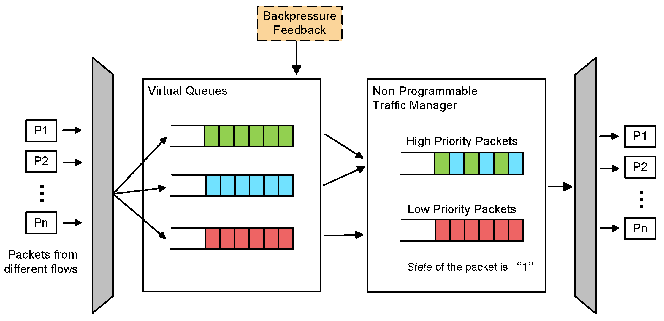
2.2. Traffic Management in Data Centers

Unlike the end-to-end congestion control schemes discussed in Section 2.1, flow control places more emphasis on network traffic management. End-to-end congestion control deals primarily with issues related to network congestion and fairness among competing flows. Flow control is more localized and aims to prevent congestion and optimize resource utilization on specific communication paths.
The priority-based flow control (PFC) [28] scheme operates as a per-hop per-flow flow control mechanism. When a switch detects incoming packets exceeding the preset threshold of a buffer, it sends a “Pause Frame” to the upstream, effectively halting further upstream traffic to prevent buffer overflow in the switch. However, the PFC scheme can suffer from head-of-line (HOL) blocking and deadlock issues. More serious cases produce a congestion-spreading phenomenon. In addition to this, there are some scheduling strategies that prioritize short flows using switches, such as pFabric [29], Homa [30], and NDP [31]. These types of traffic scheduling schemes do not inherently reduce buffer occupancy and may potentially fill up the buffer.
As the technology continued to develop, Cheng et al. revisited the congestion management architecture from another perspective and proposed the photonic congestion notification (PCN) [32]. PCN introduces a new congestion detection and identification mechanism. If 95% of the packets received during a congestion notification packet (CNP) generation period are marked as ECN, the flow is considered congested. PCN is the first scheme to handle congestion from the standpoint of identifying congested flows. Subsequently, the ternary congestion detection (TCD) [33] scheme was proposed to redefine the state of the switch port as congestion, non-congestion, and undetermined. The transition between ternary states can be detected by observing the evolving transmission patterns and queue lengths in switches. TCD accurately detects congested ports and identifies congested and undetermined flows. Both PCN and TCD handle congestion more accurately by introducing congestion signaling at the flow level to enhance network performance and fairness. However, they still rely on the traditional sender-driven rate reduction mechanism, which requires at least 1-RTT for the rate to converge to the speed of the adapted link.
Goyal et al. proposed BFC [2], a protocol for per-hop per-flow flow control. BFC calculates a pause threshold based on the occupancy of the active flows at the switch port. It allows the upstream to adjust the flow transmission by pausing or resuming based on downstream congestion conditions. However, methods like BFC and PFC that directly suspend the transmission of upstream traffic tend to be too aggressive. It can lead to the accumulation of queues and the spread of congestion. To some extent, it also affects the throughput of congested flows.
In a per-hop per-flow flow control scheme, the upstream switch implements congestion control in a one-hop RTT instead of an end-to-end RTT. The faster response time allows the upstream switch to act quickly compared to end-to-end congestion control. The research challenge is to effectively manage the buffer queues of the switches and design complex flow control policies. The PDP effectively addresses these issues. With the help of PDP, it is possible to rapidly and comprehensively reconfigure processes like packet parsing and forwarding in the network, achieving true programmability across all devices in the network [7,9,26]. This enables the on-demand management of switch buffers, leading to precise flow control to alleviate network congestion.
This congestion control strategy ensures the efficient use of network resources and reduces wasted bandwidth by providing precise per-flow control. When the network experiences congestion problems, per-hop per-flow flow control can quickly slow down or stop the transmission of congested traffic to congested nodes without affecting other non-congested flows. Responding to congestion in time can prevent packets from being excessively queued on the switch, thus reducing the end-to-end latency. In addition, rate control is combined with flow control. The switch adjusts the transmission rate as soon as it receives a congestion signal from downstream. The rate control of the switch is added to the flow control mechanism, and the congestion problems can be solved more flexibly and quickly.

3. Congestion Detection and Identification

Congestion detection is a crucial step in flow control. Only after detecting congestion can we further identify the flow affected by congestion and then adjust the transmission rate of the flow. In this section, we observe changes in the switch buffer and design a congestion detection and congested flow identification scheme.

3.1. Observations and Insights

In DCN, the PDP enables efficient packet processing and traffic management. Programmatically defining the processing logic of the data plane enables flexible deployment and management of network functions. P4 [34] is used as a domain-specific programming language to program the data plane. P4 can flexibly define various packet processing and forwarding logics and enables the programmable switches to more flexibly process and make decisions about packets, thus realizing fine-grained and efficient packet processing [35]. It is possible to obtain various information about packets passing through the current switch using P4, such as ingress and egress timestamps, ingress and egress port numbers, enqueue and dequeue depths, and so on.
Among them, queue delay and queue depth are two signals that react to network congestion. In the PDP, when a packet enters the queue for the first time, the packet queue depth (enq_qdepth, in units of the number of packets) can reflect the number of packets waiting to be processed in the switch queue. The packet queue delay is the time spent by the packet in the queue (deq_timedelta, in microseconds). The queue delay can be used to evaluate the processing power and efficiency of the switch.
The queue depth reflects the number of packets waiting to be processed in the queue but does not directly reflect the queue delay or transmission delay of the packets. In some cases, there may be a large transmission delay, even if the queue depth is small. This may affect user experience and application performance. Therefore, we observe the relationship between them through experiments to provide design concepts for congestion detection methods.
To observe the relationship between queue delay and queue depth, we perform simulation tests under the topology shown in Figure 1. It contains three senders and one receiver. The link bandwidth is set to 10 Mbps, and the sending rate is set to 1000 pps. The marking threshold is set, and the packet marking is observed based on the queue depth. Switch 3 is the node where three flows share the buffer queue. Therefore, the experiment focuses on observing the changes in the buffer queue of Switch 3, as shown in Figure 2. When the switch processes about 200 packets, the queue depth grows dramatically. The switch buffer is filled quickly and kept in a high queue state, as shown in Figure 2a. Traffic A from Sender 1, Traffic B from Sender 2, and Traffic C from Sender 3 are all marked as congested, as shown in Figure 2b.
This experiment shows that there is indeed congestion at Switch 3. Without comparing congestion with the other two switches, it is uncertain if there is a problem with multiple congestion points. The relationship between queue depth and queue delay is unknown. Based on these two issues, a new experiment is designed.
The test scenario is adjusted to have the link bandwidth set to 1 Mbps, and the sender sends traffic to the receiver at a rate of 500 pps for 10 s. The queue depth and queue delay of the packets are captured, and the buffer information of Switch 1 and Switch 3 is observed, as shown in Figure 3. The buffer information of the packet passing through Switch 1 is shown in Figure 3a, and the buffer information passing through Switch 3 is shown in Figure 3b. When congestion occurs on a network device, the number of packets in the queue increases, resulting in an increase in queue delay. Excessive queue delay usually indicates insufficient processing power of the network device or insufficient network resources.
In order to compare the congestion in response to the queue delay between different switches, the cumulative distribution function (CDF) of the queue delay of different switches is plotted, as shown in Figure 4. Using PDP to read the packets passing through the switch, it can be seen from the figure that the packets in the buffer have accumulated, and the queue delay has increased. When multiple flows pass over the link, Switch 3 is more prone to congestion, and the degree of congestion is more severe, with Switch 1 having the next highest degree of congestion and Switch 2 having the lowest degree of congestion.
Various problems arise in network nodes when traffic from different senders jointly compete for bandwidth. The prerequisite for solving network congestion is to detect congested nodes. Combining congestion signals such as queue depth and delay is more effective than relying on a single signal for a congestion description. Therefore, it is necessary to use the findings of the test experiments as a basis for further research.

3.2. Congestion Determination

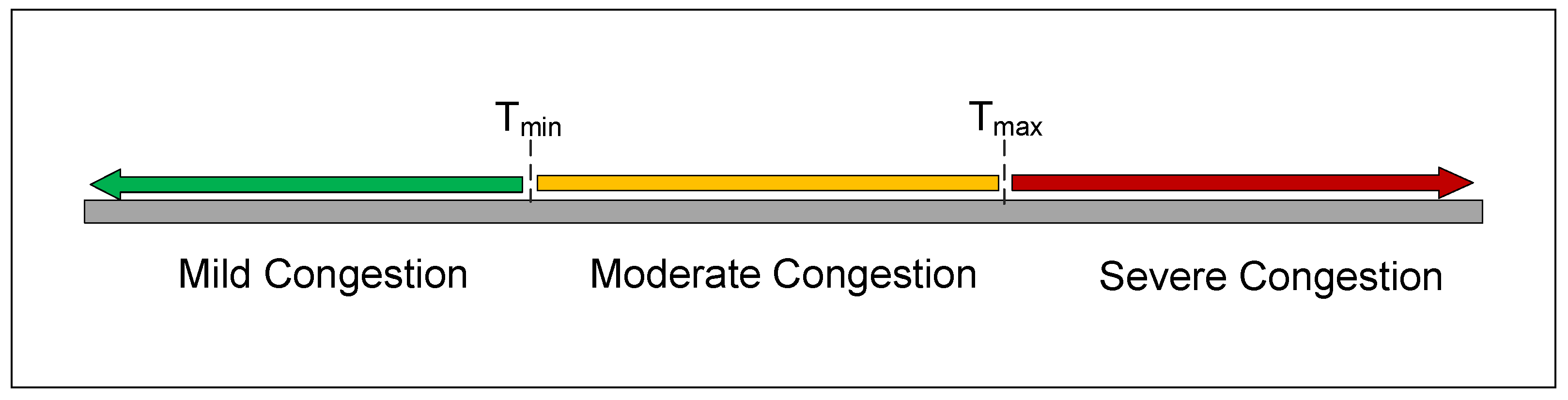
3.2.1. Division of Congestion Degree

Detecting congestion with only a single signal of queue depth or queue delay can no longer be adapted to complex network environments. To achieve more accurate congestion detection, a combination of multiple congestion signals is required. By dividing congestion into different degrees, the network can develop appropriate forwarding strategies based on the degree of congestion to improve the efficiency and fairness of the network. From the feedback results in Section 3.1, the queue delay in the PDP is also a signal that quickly indicates the degree of congestion. Therefore, the congestion degree can be divided based on queue depth and queue delay. The queue delay of the standard metadata for packets (standard_metadata. deq_timedelta) reflects the time spent in the queue for the current packet. The larger the value of queue delay, the more severe the congestion. Conversely, the smaller the value, the lighter the congestion.
Previous research has typically focused on using RTT measurements to evaluate overall end-to-end queue delays across multiple aggregation switches rather than examining queuing conditions at a single switch. Unlike end-to-end RTT, deq_timedelta reflects the time it takes for a packet to pass through the current switch, which provides insight into congestion at the current node. Focusing the congestion determination on a single node in the network provides better information about the node. It is essential to accurately identify congested nodes during traffic transmission. Corresponding measures can be taken in a timely manner by accurately capturing congested nodes in order to optimize network performance and provide a good user experience.
We use the standard metadata enq_qdepth as a metric of congestion detection, which is similar to the traditional ECN marking approach. We detect the congestion of the current node by queuing time packet arrivals. Based on testing (as described in Section 3.1), we found that about 40% of packet congestion is detected when the queue length threshold is set to 15. This approach efficiently addresses the congestion problem in a small area while maintaining low buffer characteristics.
In addition, we introduce the standard metadata deq_timedelta to further divide congestion into three degrees: mild congestion, moderate congestion, and severe congestion. The current congestion degree is divided according to T min and T max , as illustrated in Figure 5. Through extensive testing, we found that by setting T min to 80,000 and T max to 150,000, approximately 40% of congestion is equally divided into the three degrees mentioned above. This helps us treat different degrees of congestion fairly. To represent the degree of congestion in a packet, we define a two-byte bit (meta.congestion_degree) in the packet metadata. The specific marking method is shown in Table 1. Analyzing the collected packet data allows us to assess the current degree of congestion at the switches, thus helping control network congestion more effectively. Different degrees of congestion require tailored management strategies.
The advantage of dividing the congestion degree is that it provides a more accurate congestion control mechanism, which improves network performance and stability. The frequency of congestion feedback messages increases as the congestion degree is divided, leading to frequent rate control changes. These increase the burden on the switch, reduce the performance of the switch, and affect the stable transmission of network traffic. The three degrees of congestion were chosen to provide the switch with simple and clear instructions, ensuring that the rate control for three degrees of congestion still maintains a stable transmission of traffic. This approach helps determine the location and extent of congestion, allowing for faster response and ultimately optimizing the performance of the network.

3.2.2. Congested Flow Identification

Switch buffers handle traffic from different senders. When congestion occurs, pausing or slowing down all flows affects the transmission of non-congested flows. Therefore, it is necessary to identify the real-congested flow and adjust its transmission rate after dividing the degree of congestion.
The ideal solution identifies a congested flow based on a hash of the flow identifier (FID) for the flow five-tuple information, and the upstream switch reduces the delivery of that flow. This option is theoretically feasible, but it is difficult to implement in practice. The switch would need to record information about all passing flows and look up information about congested flows, which would take up a lot of resources.
From another perspective, once the degree of congestion in the switch buffer is detected, the percentage of packets per flow in the current queue is calculated to determine the congested flow. To monitor queue occupancy at each point in time, we establish a register on the switch to keep track of packets. This register records the number of packets coming from different flows. Upon detecting congestion, the register is read to calculate buffer occupancy in real time. The greater the percentage of packets from the same flow in the buffer, the greater the contribution of that flow to the current congestion of the switch. The real-congested flow can be identified by analyzing the percentage of packets in the queue.
Programmable switches provide different types of state objects to maintain the state between packets, such as tables, counters, meters, and registers. Among these, registers serve as one of the defining features of next-generation programmable switches, providing a register memory accessible in the data plane for packets to read and write various states at line rate. In the mechanism of identifying real-congested flows, a register serves as a counting function with no more complex operations. Therefore, it does not affect the read and write operations of the registers regardless of the state of the network.

4. BFCC

As a network switching device, a programmable switch has the ability to flexibly configure and adjust switching rules to accommodate traffic demands. This feature enhances data exchange and network management. A programmable switch receives and executes network configuration, management, and flow control from the controller. Although the primary function of a switch is to forward packets, the versatility of programmable switches allows for the consolidation of other functions, such as rate control.
A switch-driven congestion control architecture is designed in which the switch is programmed using the P4 language to enable it to act as a sender and the congestion response time is reduced from a 1-RTT to a one-hop RTT. This approach shifts the speed-down operation from the endpoints to the switches, with the aim of alleviating the downstream congestion in the shortest time possible.

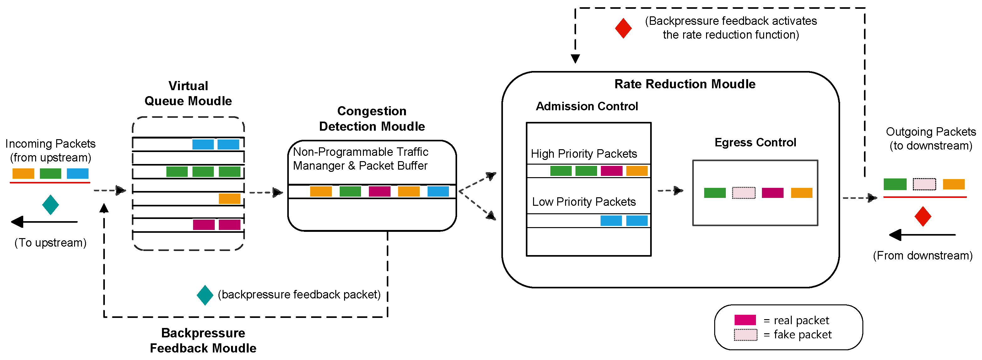
4.1. Structure Design

The basic composition of the BFCC scheme is shown in Figure 6 and mainly consists of the following modules: virtual queue module, congestion detection module, backpressure feedback module, and rate reduction module. (1) In the virtual queue module, the packets from the same sender are divided into the same virtual queue, identified as the same group of flows, and mapped to the FIFO queue in the switch buffer. (2) The congestion detection module detects the congestion of the current node and identifies the congested flow based on the queue packet occupancy. (3) The backpressure feedback module generates backpressure feedback on the congested flow based on the congestion of the node and sends it upstream. (4) The rate reduction module is composed of two parts: the admission control for the ingress pipeline and the egress control for the egress pipeline.
Virtual queue module. This module introduces the concept of a virtual queue, which does not hold any packet and does not have any effect on traffic. It is just a number that increments as packets arrive and decrements as packets leave. Traffic from the same sender is set to the same virtual queue, forming a group of flows. Each switch is the same virtual queue division, using registers to record and update the number of packets in different virtual queues.
Congestion detection module. The role of this module is to determine the level of congestion in the current node and identify the real congested flow. The real-congested flow ID is the virtual queue to which it belongs.
Backpressure feedback module. The key to bridging the two core modules of congestion detection and rate reduction in this mechanism is the delivery of congestion information. The method of generating backpressure information is to make use of the clone/mirror packet feature in P4. This operation allows packets to be copied into a number of different packet paths to enable functions such as network traffic monitoring and analysis.
The information about the congestion situation of the switch and the congested flow is added to the header of the cloned packet, which evolves into a new packet carrying the congestion information. However, since the programmable switch has to process a large number of packets per second, if the feedback packets are generated in the above way for a certain period of time, a large number of feedback congestion packets are generated in that period of time, which aggravates the burden of the switch. Through the tests, we found that congestion occurs by generating thousands of feedback packets, in which there are consecutive packets carrying the same feedback information.
To solve this problem, we establish a dedicated register in the egress pipeline that records/updates the feedback information each time. Before generating a new feedback packet, the last feedback recorded in the register is compared. If it is different, a new backpressure feedback packet is generated, and the register is updated. With this method, we observe that the probability of generating a feedback packet is reduced by 70% compared to the original, which greatly reduces the burden on the switch.
Rate reduction module. This module is implemented through the collaboration of two parts: the control of the ingress and egress pipeline. Unlike the sender side of the rate reduction, the switch independently implements the traffic rate reduction by introducing a “fake packet” to relieve the downstream node’s congestion more rapidly.

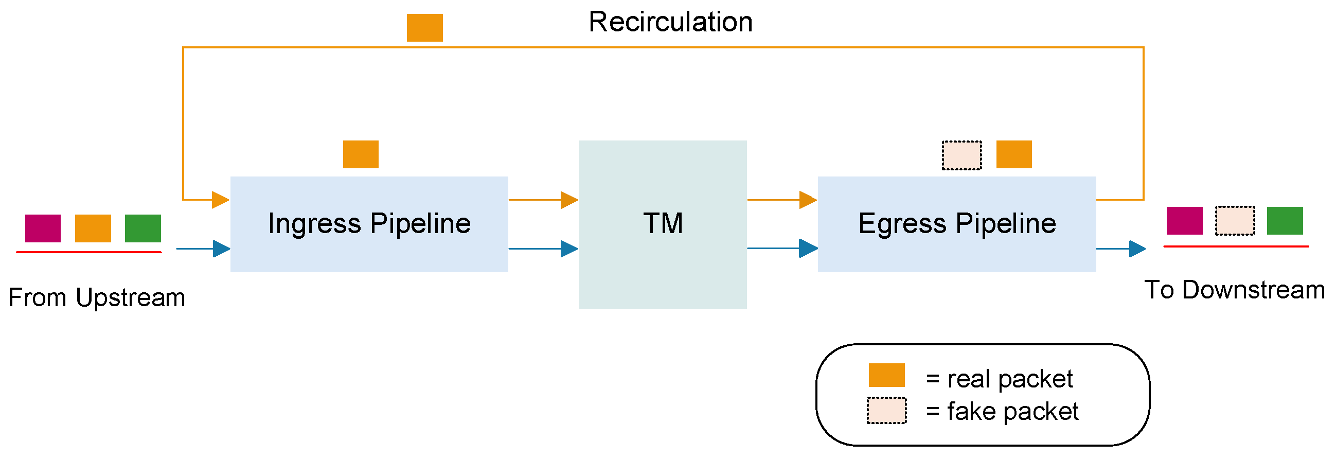
4.2. Rate Reduction Module

The module is implemented with the help of two collaborative parts, the control at the ingress pipeline and the control at the egress pipeline, which are divided into two speed reductions. The admission control at the ingress pipeline enables the management of the classification of congested and non-congested flows, while the egress control in the egress pipeline decides whether packets continue to be forwarded or not.

4.2.1. Admission Control

Traffic priority scheduling is a network traffic management method used to prioritize different flows in order to correctly allocate bandwidth and resources in the network. By setting flow priorities, the network can cater to critical applications, provide a better user experience, and ensure that network services are fair and efficient. The priority queue is a simple and straightforward traffic scheduling method that divides packets into different queues based on their priorities. When transmitting packets, the device first queues out the packets in the high-priority queue and then processes the packets in the low-priority queue. This approach ensures a fast transmission of high-priority packets.
With the concept of priority scheduling, when receiving the backpressure feedback information from the downstream, the switch immediately reacts and starts the scheduling strategy. According to the idea of priority scheduling, the congested flows are classified as low priority while the non-congested flows go to high priority. As illustrated in Figure 7, a delayed sending of congested flows is achieved using high and low priority scheduling. When the scheduling is enabled for later incoming traffic, the ingress packet is inserted into a field called “state”, which is used to keep track of whether or not a slowdown has been enabled, with 0 being “False” and 1 being “True”. In the switch traffic manager (TM), the priority queue is equivalent to a black box, and the low-priority pair is the speed-down queue. Traffic that contributes significantly to downstream congestion is classified upstream into the speed-down queue, while other traffic is sent quickly into the high-priority queue at the previous speed.
Assigning high priority ensures the faster forwarding of non-congested traffic, providing them with a higher bandwidth allocation, while low-priority traffic can be restricted or adjusted according to network congestion to prevent congested flows from placing a greater burden on the downstream traffic. With the help of this method, access control is introduced in the ingress pipeline to perform the first speed reduction of congested flows, with the specific algorithm outlined in Algorithm 1.
Algorithm 1 Pseudo-code of the BFCC algorithm implemented at the ingress pipeline of the PDP
Input:
Packet p, Backpressure−Feedback−Packet bfp, Virtual−Queue vq;
Output:
None
  1:
if  b f p . c o n g e s t i o n _ d e g r e e != 0 b f p . v q != 0 then
  2:
   Set p a c k e t _ s t a t e ;
  3:
   if p. v q == b f p . v q  then
  4:
     Set high priority;
  5:
   else
  6:
     Set low priority;
  7:
   end if
  8:
else
  9:
   Set high priority;
10:
end if
11:
Update register of the virtual queue to count packets.

4.2.2. Egress Control

Because of the introduction of the scheduling strategy, the sending of congested flows is reduced, but the non-congested flows in the high-priority queue grab the bandwidth and forward at high speeds, which does not alleviate the downstream congestion problem. Therefore, on top of scheduling, we introduce a new control module before the packets are sent out of the port.
The control module of the egress pipeline decides whether packets are forwarded downstream or not and monitors the packets that are scheduled to be forwarded at the ingress pipeline. The egress control module monitors the “state” field in the packet and triggers the egress control policy if it is set to “True”. With flexible programmability, switches can be customized and extended to achieve specific forwarding, filtering, processing, and management functions.
Unlike PFC, which directly pauses queue transmission, there is no equivalent operation in programmable switches. With the help of the idea of sender-side rate reduction in congestion control, a rate reduction strategy is designed between the switches. The rate reduction module is depicted in Figure 8. We define a register in the egress pipeline to record the real packets forwarded downstream; when the set threshold is reached, a copy of the packet (referred to as the “fake packet”) is cloned and continues to be forwarded instead of the original while the original packet is retransmitted into the ingress pipeline. Since the “fake packet” does not exist in the original flow, it is forwarded downstream and discarded. By inserting fake packets, we can achieve the effect of rate reduction while making full use of the bandwidth.
Recirculation. The switch has a dedicated internal link for recirculating, which does not affect the queue length on the egress port. For example, if 1% of the packets need to be cloned, the recirculation increases the bandwidth only by 1%; if each packet is cloned, the volume of packets processed at the ingress is doubled.
Programmable switches can process a large number of packets per second. By harnessing the robust computational capabilities of the PDP, the function of rate reduction can be delegated to switches. After conducting extensive testing on this module, we reach the following conclusions.
During mild congestion downstream, the upstream rate threshold is set to 9. This means that for every 10 packets sent through the egress pipeline, 1 “fake packet” is inserted, and the speed is reduced to 9/10 of the original. For moderate congestion, the threshold is set to 3; the speed is reduced to 3/4 of the original. In the case of severe congestion, the speed quickly converged to half of the original. And, when the sender receives a congestion feedback packet from the switch, the reduced sending rate is the same as that of the switch. The algorithm for the egress pipeline is shown in Algorithm 2.
Algorithm 2 Pseudo-code of the BFCC algorithm implemented at the egress pipeline of the PDP.
Input:
Packet p, Backpressure−Feedback−Packet bfp, Rate−Threshold RT, T m i n , T m a x , CONGESTION THRESHOLD;
Output:
None
  1:
/ / Detect congestion
  2:
if  e n q _ q d e p t h > CONGESTION THRESHOLD then
  3:
   if  d e q _ t i m e d e l t a < = T m i n  then
  4:
     Set m i l d _ d e g r e e ;
  5:
   else if  d e q _ t i m e d e l t a > T m i n  and  d e q _ t i m e d e l t a < = T m a x  then
  6:
     Set m o d e r a t e _ d e g r e e ;
  7:
   else
  8:
     Set s e v e r e _ d e g r e e ;
  9:
   end if
10:
    / / Congested flow identification
11:
   Compute Max( q u e u e _ o c c u p a n c y )
12:
end if
13:
Generate bfp;
14:
/ / Secondary deceleration in upstream switch
15:
if p. s t a t e is True then
16:
   if  d e q u e u e d _ p a c k e t s > RT then
17:
     Clone;
18:
     Recirculate(p);
19:
   end if
20:
end if

5. Evaluation

Simulations and tests were performed on a Mininet with a P4 switch simulator (BMV2 [36]) to evaluate the performance of the proposed strategy. A comparison was carried out between its performance and existing schemes to validate its feasibility.

5.1. Evaluation of Single-Receiver Topology

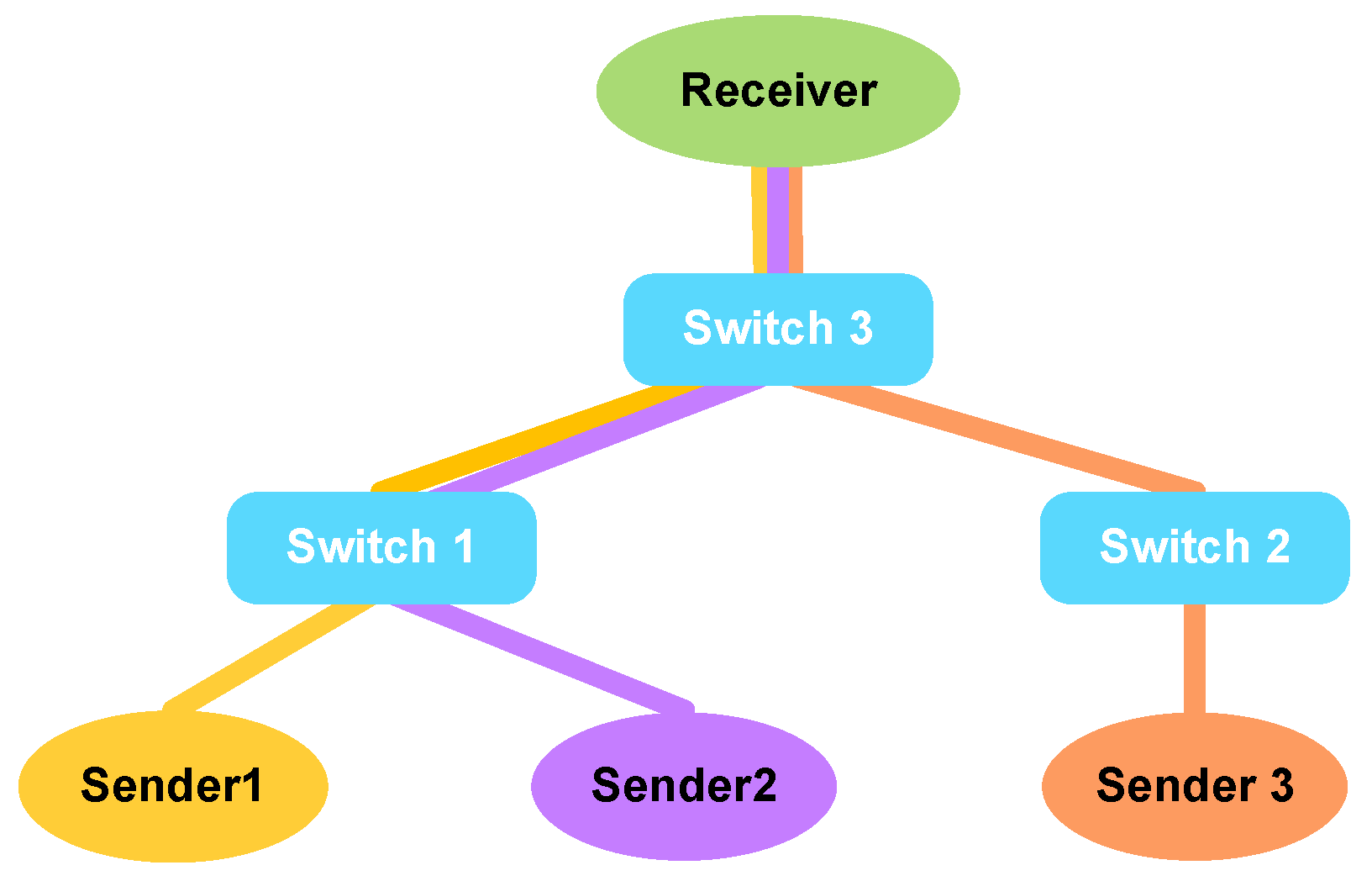
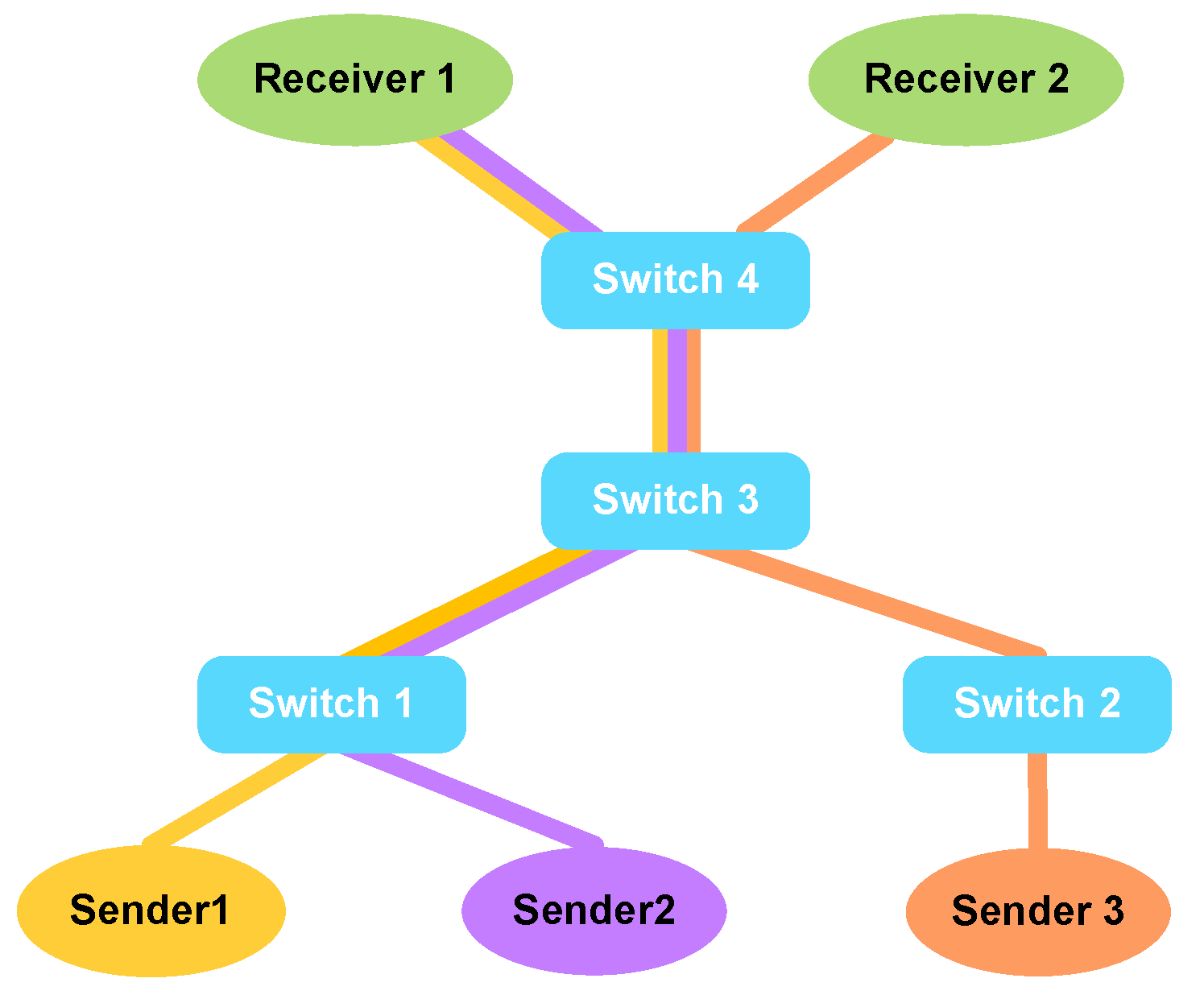
5.1.1. Experiment Settings

The comparison test was performed under the network topology of Figure 1, and the experiment was divided into 3 groups of streams, with each sender belonging to the same group of flows. The path of each group of flows is shown below.
  • Sender Group 1 → Switch 1 → Switch 3 → Receiver
  • Sender Group 2 → Switch 1 → Switch 3 → Receiver
  • Sender Group 3 → Switch 2 → Switch 3 → Receiver
We compared BFCC with existing end-to-end congestion control schemes (e.g., P4QCN, TCN, DCQCN). The comparison primarily focused on four performance metrics: (1) FCT of single flow; (2) throughput; (3) RTT per packet; (4) queue length of the buffer.
BFCC. BFCC implements switch-to-switch congestion control by detecting congestion based on buffer queue depth and queue delay and identifying congested flows by analyzing queue occupancy. The parameter for detecting congestion threshold was set to 15, with T min = 80,000 and T max = 150,000.
DCQCN. DCQCN [18] uses ECN marking and end-to-end congestion control to manage buffers on switches. To unify the test environment, we implemented DCQCN on a P4-based Mininet, matching all the details in the original paper. DCQCN was used as a comparison because it is still commonly used in today’s data centers. The specific parameter settings were K min = K max = 11, g = 1/256, N = 50µs, and K = 55 µs.
P4QCN. P4QCN [37] is a flow-level rate-based congestion control protocol using ECN marking policy to mark congestion and extends the QCN protocol to make it compatible with IP routing networks based on the P4 framework. We implemented P4QCN and set the parameters as suggested in the paper: Q p 4 QCN = Q min = Q max = 11, N = 5, β = 1, and R AI = 5 Mbps.
TCN. TCN [38] is a time-based display congestion feedback control mechanism that uses the waiting time of the packet rather than queue length, as a congestion signal; ECN marking thresholds are computed based on the current packet’s delay. TCN is stateless as it does not modify the state in the data plane by performing stateless transient ECN marking.

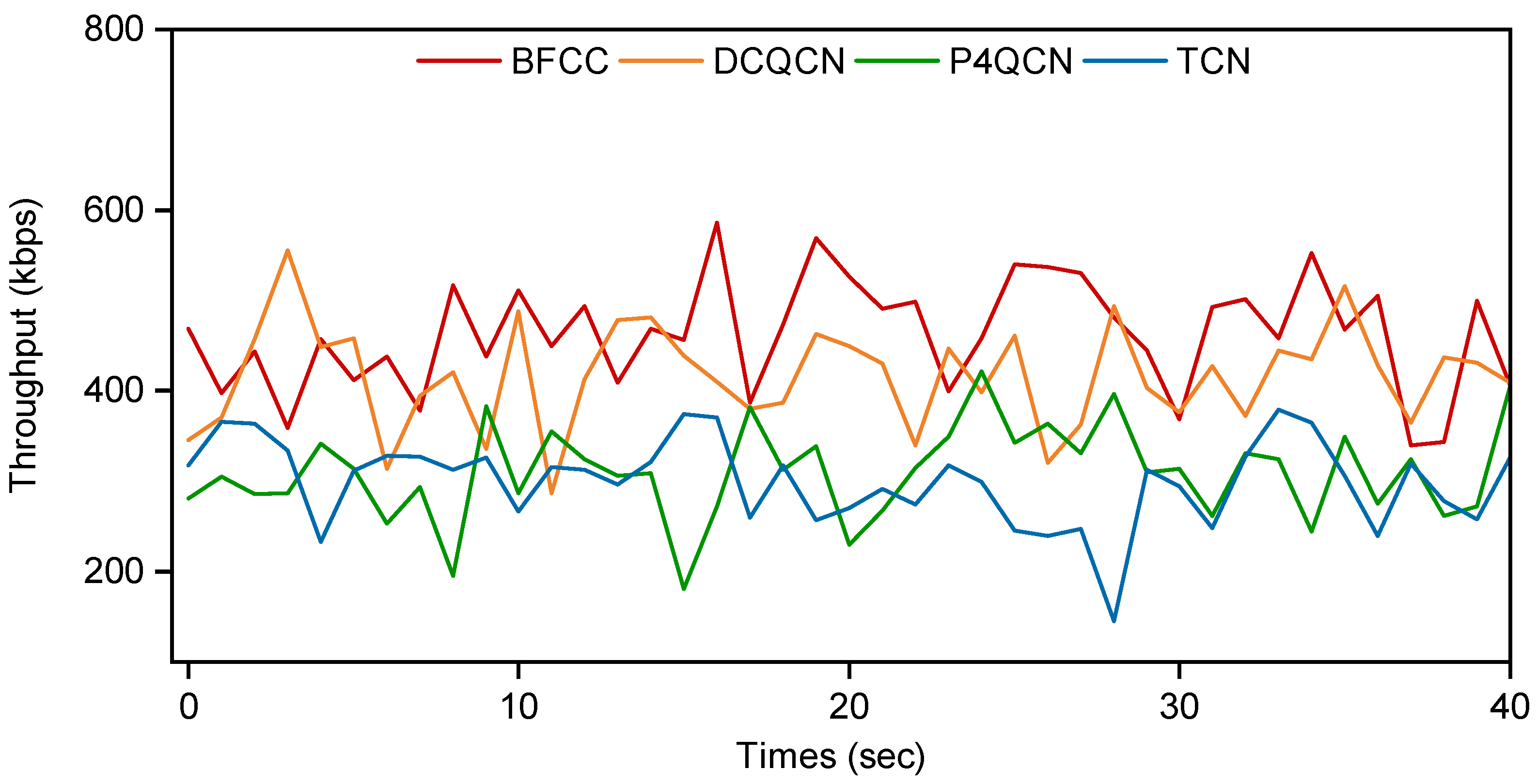
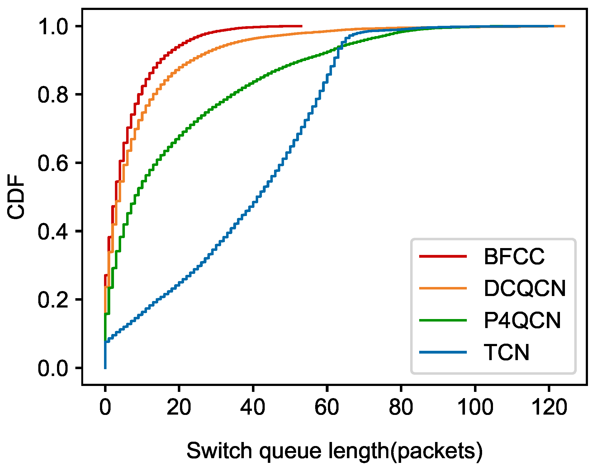
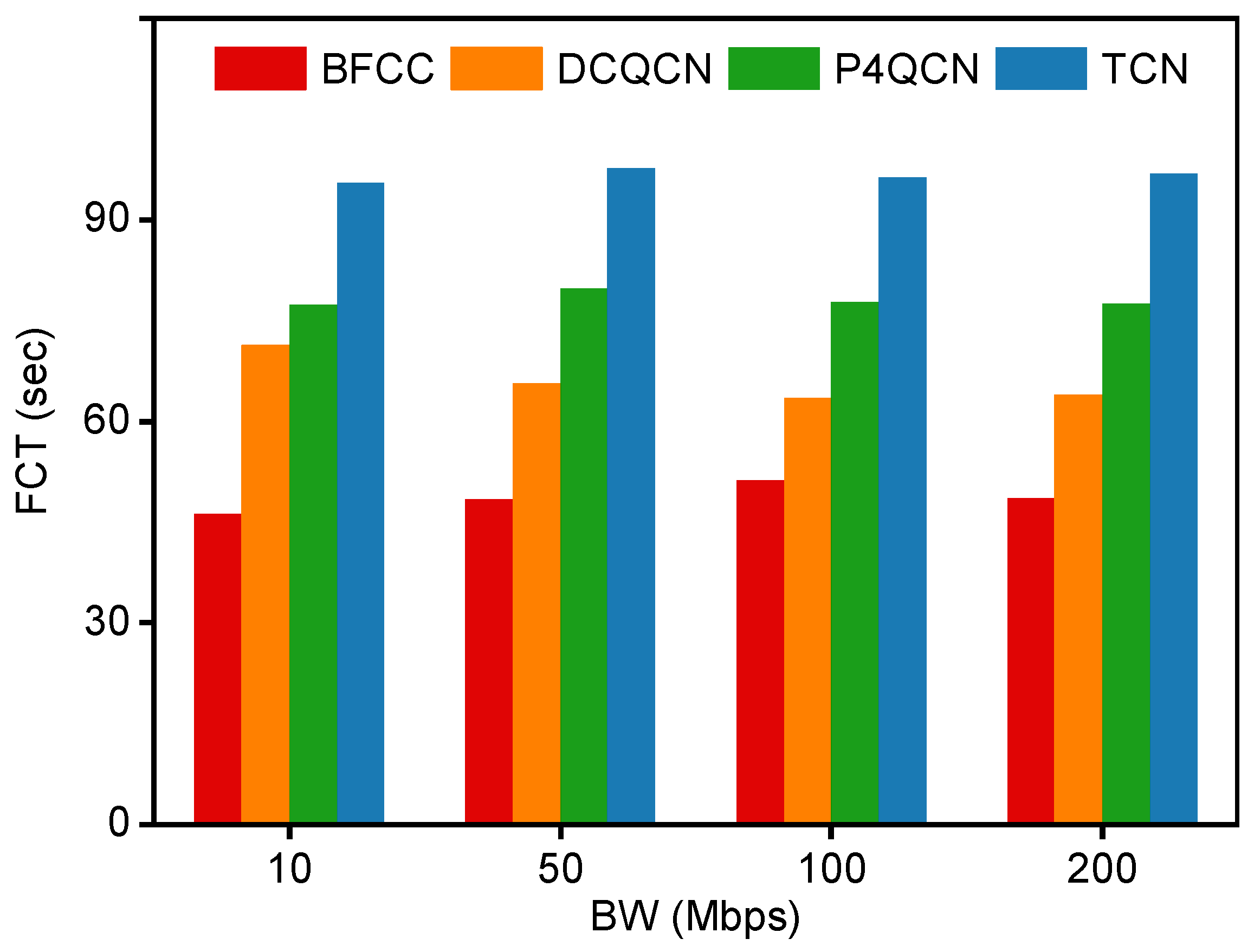
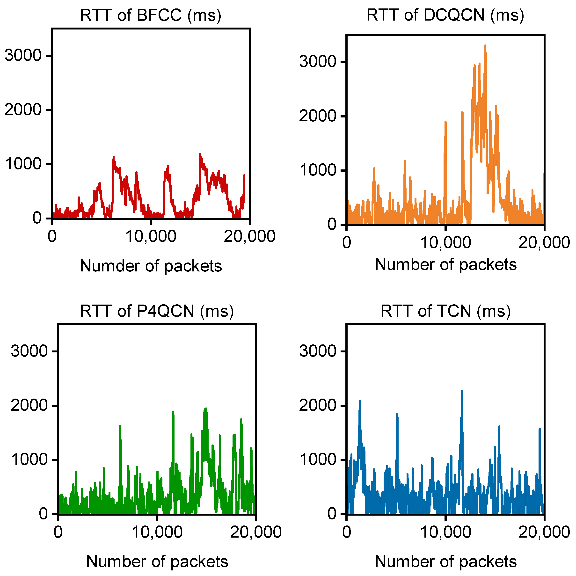
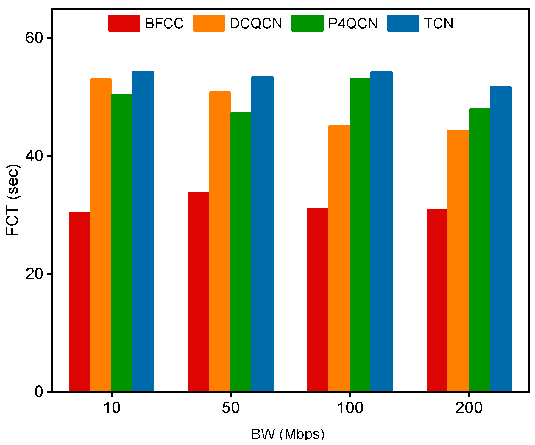
5.1.2. Experiment Results

Based on the findings in Section 3.1, it is learned that Switch 3 is the most prone to congestion when three groups of flows compete at the same time. To evaluate the simultaneous competition of three groups of flows, we set the link bandwidth to 10 Mbps in the network topology shown in Figure 1, and each group of flows had a size of 1 MB (with a packet size of 128 B) and concurrently sent traffic to receiver.
Figure 9 shows the comparison between BFCC and the other schemes in the metric of throughput. It can be observed from the graph that the throughput of the congestion control scheme can reach up to 600 kbps, and the average throughput was around 450 kbps, which is better than the other three schemes. For the other three schemes combined with the rate control at the endpoints, the throughput fluctuations were more obvious. BFCC achieved rate adjustment between the switches, there was no sender rate reduction strategy, and the overall throughput level was maintained at a high level.
In the metric of buffer queue length, we focused on observing buffer changes under congestion point number 3. We sampled the queue lengths in the switches and analyzed their cumulative distribution. Figure 10 shows the CDF under the four schemes. The differences between these schemes can be seen, where it can be observed that the BFCC mechanism is at a lower buffer queue length and guarantees a high throughput while maintaining the low buffer characteristics. It can also be shown that the switch direct action approach is slightly better than the endpoint control scheme.
In order to test the FCT under different scenarios, the link bandwidth was adjusted to analyze the differences between different schemes. The link bandwidth was adjusted from 10 Mbps to 50 Mbps, 100 Mbps, and 200 Mbps, and the FCT was observed for three groups of flows sent at the same time. As shown in Figure 11, with different link bandwidths, the BFCC maintained the lowest FCT, which shows that the switch-to-switch congestion control mechanism ensures high throughput and low latency with low buffer. In terms of the overall FCT, BFCC achieves completion times 1.2–2× faster than other ECN schemes. Because of the limitation of BMV2, the test could not simulate the high link bandwidth in the real network, and the different bandwidths of 10 Mbps, 50 Mbps, 100 Mbps, and 200 Mbps were set for the metric of FCT in order to simulate the state of the link bandwidth constantly changing in DCN. Through the results, it was observed that BFCC demonstrated better experimental performance.
In addition to this, the RTT per packet was also compared, as shown in Figure 12. As mentioned in Section 4.2, the design of the BFCC mechanism involves the recirculation of packets, which can lead to slightly higher RTT for some packets, but overall, it is still low and stable. From this, it can be seen that using collaboration between switches to solve the congestion problem is faster than two-point architecture (endpoint-switch) and three-point architecture (endpoint-switch-endpoint).
According to the tests conducted in Section 3.1, it is known that in addition to Switch 3 being the most congested when three groups of flows compete at the same time, Switch 1 has two groups of flows sharing the buffer. Other scenarios were set up to evaluate the competition between Group 1 flow and Group 2 flow at Switch 1. At a bandwidth of 10 Mbps, the Group 2 flow changed from the previous 1 MB to 2 MB, 4 Mb, and 8 MB, and the Group 1 flow remained at 1 MB. Analyzing the FCT of Group 1 flows under the influence of Group 2 flows, Figure 13 illustrates that BFCC of Group 1 flows experienced the shortest completion time during the competition, significantly enhancing the flow completion rate.

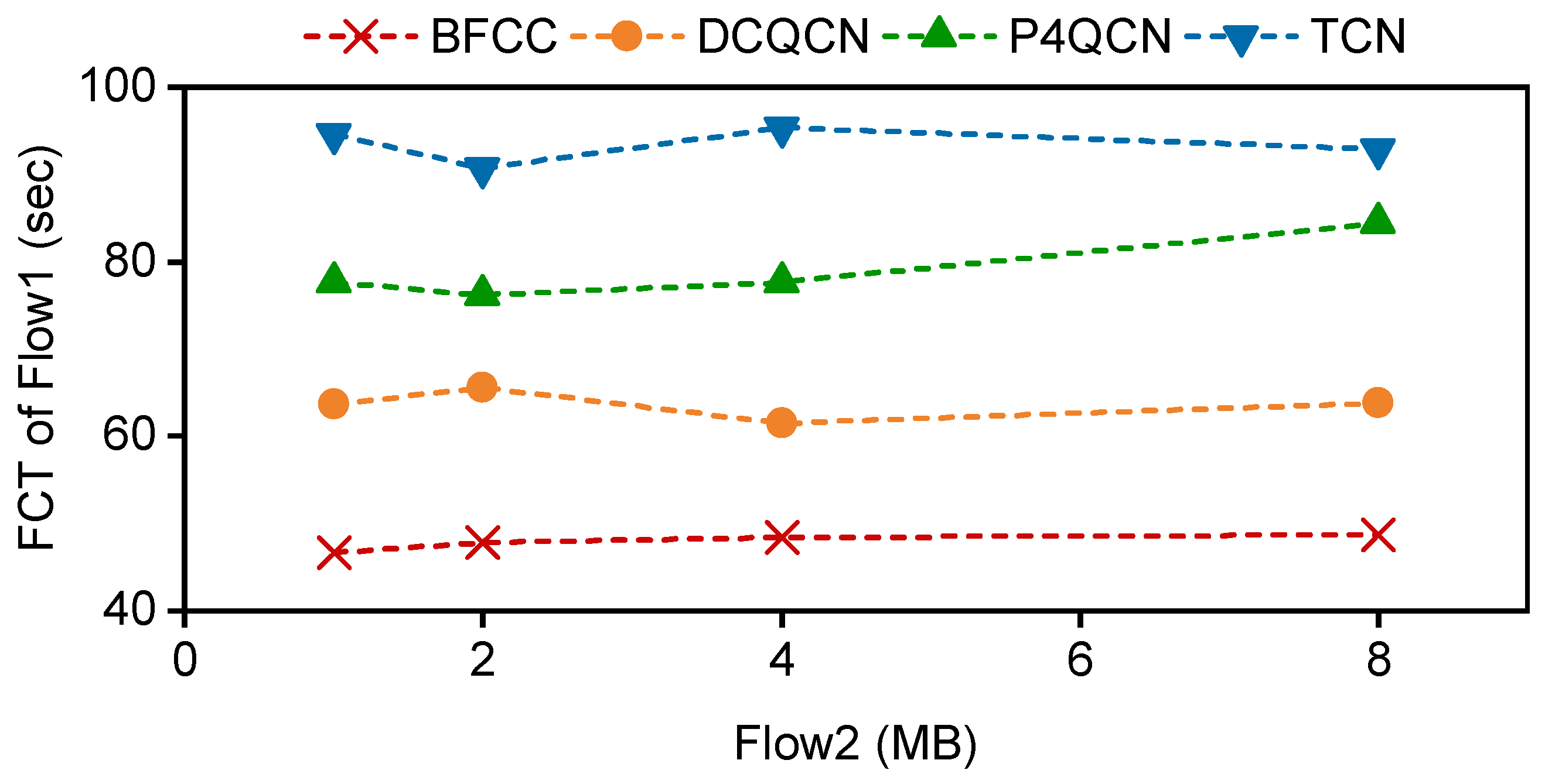
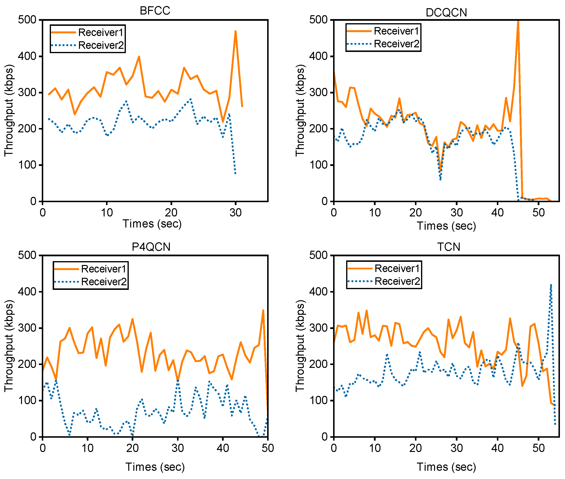
5.2. Evaluation of Two-Receiver Topology

We changed the topology as shown in Figure 14, which consists of three senders, four BMV2 switches, and two receivers. Sender 1 and Sender 2 send traffic to Receiver 1; Sender 3 sends traffic to Receiver 2. The link bandwidth was 10 Mbps, and the traffic size was 1 MB. The parameter settings of BFCC, DCQCN, P4QCN, and TCN were the same as in Section 5.1. High throughput and low latency are two important goals in DCN. Therefore, we evaluated the four schemes mainly in terms of two performance metrics: throughput and FCT.
We compare the throughput of traffic sent to Receiver 1 and Receiver 2, as shown in Figure 15. For the throughput of the traffic destined for Receiver 1, the throughput of the BFCC scheme is above 300 kbps and more stable. The throughput of DCQCN is less than 300 kbps, which maintains the throughput at 200 kbps. The throughput of the P4QCN scheme is around 250 kbps. The TCN scheme is also not as good as the BFCC. As for the traffic sent to Receiver 2, the BFCC scheme best represents the stability of the traffic, with throughput maintained at 200 kbps. Overall, the congestion control scheme proposed in this paper is based on per-flow management. Thus, the flows on both links maintain high throughput without affecting each other.
The link bandwidth was changed from 10 Mbps to 50 Mbps, 100 Mbps, and 200 Mbps, and the FCT of the three flows was observed, as shown in Figure 16. The BFCC scheme always maintained the lowest FCT at different link bandwidths. Specifically, the FCT of BFCC was reduced by about 44.7% compared to DCQCN. The FCT of BFCC was reduced by about 39.8% compared to P4QCN. Meanwhile, the FCT of BFCC was reduced by 44.1% compared to the TCN scheme. Essentially, BFCC ensures high throughput and low latency.

6. Conclusions

This article introduces a congestion control mechanism based on backpressure feedback, which divides congestion into different degrees, identifies real-congested flows by recognizing the occupancy of buffer queues, and generates the backpressure feedback accordingly. Meanwhile, the rate control on the switch is designed to achieve precise control of each flow group. In comparison to existing end-to-end congestion control schemes under two network topologies, switch-to-switch congestion control enhances throughput and significantly reduces transmission delay. The feasibility of the strategy is also demonstrated by implementing it on Mininet with BMV2. In future work, the approach will be validated in a real network environment.

Author Contributions

Conceptualization, W.L., M.R., Y.L. and Z.Z.; methodology, W.L., M.R. and Y.L.; software, W.L., M.R., Y.L., C.L. and H.Q.; validation, W.L., M.R. and Y.L.; investigation, M.R.; resources, W.L., Y.L. and Z.Z.; writing—original draft preparation, M.R.; writing—review and editing, W.L., M.R.,Y.L., C.L. and H.Q.; visualization, M.R. and Y.L.; supervision, W.L., Y.L. and Z.Z; project administration, W.L., Y.L. and Z.Z. All authors have read and agreed to the published version of the manuscript.

Funding

This work was funded by Science and Technology Project of Hebei Education Department ZD2022102.

Data Availability Statement

No necessary datasets has been applied in this article.

Acknowledgments

The authors gratefully appreciate the anonymous reviewers for their valuable comments.

Conflicts of Interest

The authors declare no conflicts of interest.

References

  1. Gibson, D.; Hariharan, H.; Lance, E.; McLaren, M.; Montazeri, B.; Singh, A.; Wang, S.; Wassel, H.M.; Wu, Z.; Yoo, S. Aquila: A unified, low-latency fabric for datacenter networks. In Proceedings of the 19th USENIX Symposium on Networked Systems Design and Implementation (NSDI 22), Renton, WA, USA, 4–6 April 2022; pp. 1249–1266. [Google Scholar]
  2. Prateesh, G.; Preey, S.; Kevin, Z.; Georgios, N.; Mohammad, A.; Thomas, A. Backpressure flow control. In Proceedings of the Symposium on Network System Design and Implementation, NSDI, Renton, WA, USA, 4–6 April 2022; pp. 779–805. [Google Scholar]
  3. Joshi, R.; Song, C.H.; Khooi, X.Z.; Budhdev, N.; Mishra, A.; Chan, M.C.; Leong, B. Masking Corruption Packet Losses in Datacenter Networks with Link-local Retransmission. In Proceedings of the ACM SIGCOMM 2023 Conference, New York, NY, USA, 10–14 September 2023; pp. 288–304. [Google Scholar]
  4. Poutievski, L.; Mashayekhi, O.; Ong, J.; Singh, A.; Tariq, M.; Wang, R.; Zhang, J.; Beauregard, V.; Conner, P.; Gribble, S. Jupiter evolving: Transforming google’s datacenter network via optical circuit switches and software-defined networking. In Proceedings of the ACM SIGCOMM 2022 Conference, Amsterdam, The Netherlands, 22–26 August 2022; pp. 66–85. [Google Scholar]
  5. Li, Q. TCP FlexiS: A New Approach To Incipient Congestion Detection and Control. IEEE/ACM Trans. Netw. 2023; 1–16. [Google Scholar] [CrossRef]
  6. Arslan, S.; Li, Y.; Kumar, G.; Dukkipati, N. Bolt: Sub-RTT Congestion Control for Ultra-Low Latency. In Proceedings of the 20th USENIX Symposium on Networked Systems Design and Implementation (NSDI 23), Boston, MA, USA, 17–19 April 2023; pp. 219–236. [Google Scholar]
  7. Liu, W.-X.; Liang, C.; Cui, Y.; Cai, J.; Luo, J.-M. Programmable data plane intelligence: Advances, opportunities, and challenges. IEEE Netw. 2022, 37, 122–128. [Google Scholar] [CrossRef]
  8. Bolanowski, M.; Gerka, A.; Paszkiewicz, A.; Ganzha, M.; Paprzycki, M. Application of genetic algorithm to load balancing in networks with a homogeneous traffic flow. In Proceedings of the International Conference on Computational Science, Prague, Czech Republic, 3–5 July 2023; pp. 314–321. [Google Scholar]
  9. Zaher, M.; Alawadi, A.H.; Molnár, S. Sieve: A flow scheduling framework in SDN based data center networks. Comput. Commun. 2021, 171, 99–111. [Google Scholar] [CrossRef]
  10. Scazzariello, M.; Caiazzi, T.; Ghasemirahni, H.; Barbette, T.; Kostić, D.; Chiesa, M. A High-Speed Stateful Packet Processing Approach for Tbps Programmable Switches. In Proceedings of the 20th USENIX Symposium on Networked Systems Design and Implementation (NSDI 23), Boston, MA, USA, 17–19 April 2023; pp. 1237–1255. [Google Scholar]
  11. Xiao, L.Y.S.; Jun, B.I.; Yu, Z.; Cheng, Z.; Ping, W.J.; Zheng, L.Z.; Ran, Z.Y. Research and Applications of Programmable Data Plane Based on P4. Chin. J. Comput. 2019, 42, 2539–2560. [Google Scholar]
  12. Namkung, H.; Liu, Z.; Kim, D.; Sekar, V.; Steenkiste, P. Sketchovsky: Enabling Ensembles of Sketches on Programmable Switches. In Proceedings of the 20th USENIX Symposium on Networked Systems Design and Implementation (NSDI 23), Boston, MA, USA, 17–19 April 2023; pp. 1273–1292. [Google Scholar]
  13. Agarwal, S.; Krishnamurthy, A.; Agarwal, R. Host Congestion Control. In Proceedings of the ACM SIGCOMM 2023 Conference, New York, NY, USA, 10–14 September 2023; pp. 275–287. [Google Scholar]
  14. Kundel, R.; Krishna, N.B.; Gärtner, C.; Meuser, T.; Rizk, A. Poster: Reverse-path congestion notification: Accelerating the congestion control feedback loop. In Proceedings of the 2021 IEEE 29th International Conference on Network Protocols (ICNP), Dallas, TX, USA, 1–5 November 2021; pp. 1–2. [Google Scholar]
  15. Alizadeh, M.; Greenberg, A.; Maltz, D.A.; Padhye, J.; Patel, P.; Prabhakar, B.; Sengupta, S.; Sridharan, M. Data center tcp (dctcp). In Proceedings of the ACM SIGCOMM 2010 Conference, New Delhi, India, 30 August–3 September 2010; pp. 63–74. [Google Scholar]
  16. Vamanan, B.; Hasan, J.; Vijaykumar, T. Deadline-aware datacenter tcp (d2tcp). ACM SIGCOMM Comput. Commun. Rev. 2012, 42, 115–126. [Google Scholar] [CrossRef]
  17. Wu, H.; Feng, Z.; Guo, C.; Zhang, Y. ICTCP: Incast congestion control for TCP in data center networks. IEEE/ACM Trans. Netw. 2013, 2, 235–358. [Google Scholar]
  18. Zhu, Y.; Eran, H.; Firestone, D.; Guo, C.; Lipshteyn, M.; Liron, Y.; Padhye, J.; Raindel, S.; Yahia, M.H.; Zhang, M. Congestion control for large-scale RDMA deployments. ACM SIGCOMM Comput. Commun. Rev. 2015, 45, 523–536. [Google Scholar] [CrossRef]
  19. IEEE. 802.11Qau-Congestion Notification. Available online: https://1.ieee802.org/dcb/802-1qau/ (accessed on 10 April 2024).
  20. Wu, H.; Ju, J.; Lu, G.; Guo, C.; Xiong, Y.; Zhang, Y. Tuning ECN for data center networks. In Proceedings of the 8th International Conference on Emerging Networking Experiments and Technologies, Nice, France, 10–13 December 2012; pp. 25–36. [Google Scholar]
  21. Munir, A.; Qazi, I.A.; Uzmi, Z.A.; Mushtaq, A.; Ismail, S.N.; Iqbal, M.S.; Khan, B. Minimizing flow completion times in data centers. In Proceedings of the 2013 Proceedings IEEE INFOCOM, Turin, Italy, 14–19 April 2013; pp. 2157–2165. [Google Scholar]
  22. Shan, D.; Ren, F. Improving ECN marking scheme with micro-burst traffic in data center networks. In Proceedings of the IEEE INFOCOM 2017-IEEE Conference on Computer Communications, Atlanta, GA, USA, 1–4 May 2017; pp. 1–9. [Google Scholar]
  23. Chen, J.; Jing, Y.; Xie, H. Multiple Bottleneck Topology TCP/AWM Network Event-triggered Congestion Control with New Prescribed Performance. Int. J. Control Autom. Syst. 2023, 21, 2487–2503. [Google Scholar] [CrossRef]
  24. Mittal, R.; Lam, V.T.; Dukkipati, N.; Blem, E.; Wassel, H.; Ghobadi, M.; Vahdat, A.; Wang, Y.; Wetherall, D.; Zats, D. TIMELY: RTT-based congestion control for the datacenter. ACM SIGCOMM Comput. Commun. Rev. 2015, 45, 537–550. [Google Scholar] [CrossRef]
  25. Kumar, G.; Dukkipati, N.; Jang, K.; Wassel, H.M.; Wu, X.; Montazeri, B.; Wang, Y.; Springborn, K.; Alfeld, C.; Ryan, M. Swift: Delay is simple and effective for congestion control in the datacenter. In Proceedings of the Annual Conference of the ACM Special Interest Group on Data Communication on the Applications, Technologies, Architectures, and Protocols for Computer Communication, Online, 10–14 August 2020; pp. 514–528. [Google Scholar]
  26. Wang, W.; Moshref, M.; Li, Y.; Kumar, G.; Ng, T.E.; Cardwell, N.; Dukkipati, N. Poseidon: Efficient, Robust, and Practical Datacenter CC via Deployable INT. In Proceedings of the 20th USENIX Symposium on Networked Systems Design and Implementation (NSDI 23), Boston, MA, USA, 17–19 April 2023; pp. 255–274. [Google Scholar]
  27. Lim, H.; Kim, J.; Cho, I.; Jang, K.; Bai, W.; Han, D. FlexPass: A Case for Flexible Credit-based Transport for Datacenter Networks. In Proceedings of the Eighteenth European Conference on Computer Systems, Rome, Italy, 8–12 May 2023; pp. 606–622. [Google Scholar]
  28. IEEE. 802.1Qbb—Priority-Based Flow Control. Available online: http://www.ieee802.org/1/pages/802.1bb.html (accessed on 10 April 2024).
  29. Alizadeh, M.; Yang, S.; Sharif, M.; Katti, S.; McKeown, N.; Prabhakar, B.; Shenker, S. pfabric: Minimal near-optimal datacenter transport. ACM SIGCOMM Comput. Commun. Rev. 2013, 43, 435–446. [Google Scholar] [CrossRef]
  30. Montazeri, B.; Li, Y.; Alizadeh, M.; Ousterhout, J. Homa: A receiver-driven low-latency transport protocol using network priorities. In Proceedings of the 2018 Conference of the ACM Special Interest Group on Data Communication, Budapest, Hungary, 20–25 August 2018; pp. 221–235. [Google Scholar]
  31. Handley, M.; Raiciu, C.; Agache, A.; Voinescu, A.; Moore, A.W.; Antichi, G.; Wójcik, M. Re-architecting datacenter networks and stacks for low latency and high performance. In Proceedings of the Conference of the ACM Special Interest Group on Data Communication, Los Angeles, CA, USA, 21–25 August 2017; pp. 29–42. [Google Scholar]
  32. Cheng, W.; Qian, K.; Jiang, W.; Zhang, T.; Ren, F. Re-architecting congestion management in lossless ethernet. In Proceedings of the 17th USENIX Symposium on Networked Systems Design and Implementation (NSDI 20), Santa Clara, CA, USA, 25–27 February 2020; pp. 19–36. [Google Scholar]
  33. Zhang, Y.; Liu, Y.; Meng, Q.; Ren, F. Congestion detection in lossless networks. In Proceedings of the 2021 ACM SIGCOMM 2021 Conference, Online, 23–27 August 2021; pp. 370–383. [Google Scholar]
  34. Hauser, F.; Häberle, M.; Merling, D.; Lindner, S.; Gurevich, V.; Zeiger, F.; Frank, R.; Menth, M. A survey on data plane programming with p4: Fundamentals, advances, and applied research. J. Netw. Comput. Appl. 2023, 212, 103561. [Google Scholar] [CrossRef]
  35. P4 16 PSA Specification. Available online: https://p4lang.github.io/p4-spec/docs/PSA-v1.1.0.html (accessed on 10 April 2024).
  36. P4 Behavioral Model (BMV2). Available online: https://github.com/p4lang/behavioral-model (accessed on 10 April 2024).
  37. Geng, J.; Yan, J.; Zhang, Y. P4QCN: Congestion control using P4-capable device in data center networks. Electronics 2019, 8, 280. [Google Scholar] [CrossRef]
  38. Bai, W.; Chen, K.; Chen, L.; Kim, C.; Wu, H. Enabling ECN over generic packet scheduling. In Proceedings of the 12th International on Conference on emerging Networking EXperiments and Technologies, Irvine, CA, USA, 12–15 December 2016; pp. 191–204. [Google Scholar]
Figure 1. Topology of the experiment. The colored lines show paths that differ from different traffic groups.
Futureinternet 16 00131 g001
Figure 2. In congestion scenario, queue lengths and packet marking in the switch. (a) Queue length in switch; (b) Packet marking in switch.
Futureinternet 16 00131 g002
Figure 3. The buffer situation of the switches. (a) Switch 1; (b) Switch 3.
Futureinternet 16 00131 g003
Figure 4. CDF of the queue delay in Switches 1–3.
Futureinternet 16 00131 g004
Figure 5. Division of congestion degree.
Futureinternet 16 00131 g005
Figure 6. The overall architecture of the BFCC.
Futureinternet 16 00131 g006
Figure 7. Virtual queues and admission control at the data plane. This scheme achieves the first speed reduction.
Futureinternet 16 00131 g007
Figure 8. Egress control at the data plane. This scheme achieves a second speed reduction.
Futureinternet 16 00131 g008
Figure 9. Throughput comparison of four schemes.
Futureinternet 16 00131 g009
Figure 10. Buffer queue length comparison.
Futureinternet 16 00131 g010
Figure 11. FCT in the Switch 3 congestion scenario. Four different bandwidth settings are used to compare the FCT of the four schemes.
Futureinternet 16 00131 g011
Figure 12. Comparison the RTT per packet.
Futureinternet 16 00131 g012
Figure 13. FCT for Group 1 flows competing with different large Group 2 flows.
Futureinternet 16 00131 g013
Figure 14. Two-receiver topology.
Futureinternet 16 00131 g014
Figure 15. FCT in the two-receiver topology.
Futureinternet 16 00131 g015
Figure 16. The throughput of Receiver 1 and Receiver 2.
Futureinternet 16 00131 g016
Table 1. Marking method.
2 BitMeaning
00Non-congestion
01Mild congestion
10Moderate congestion
11Severe congestion
Disclaimer/Publisher’s Note: The statements, opinions and data contained in all publications are solely those of the individual author(s) and contributor(s) and not of MDPI and/or the editor(s). MDPI and/or the editor(s) disclaim responsibility for any injury to people or property resulting from any ideas, methods, instructions or products referred to in the content.

