1. Introduction
Locating and tracking of mobile targets is mainly related to observation state variables such as angles, rate of angle changes and gradient of Doppler frequency, most of which are in line with nonlinear functions. In the traditional locating and tracking of DOA, estimation algorithms based on MUSIC, ESPRIT are widely used [
1,
2]. However, the MUSIC algorithm needs Eigen decomposition and spectral peak search, rising higher computational complexity and can not satisfy the requirement, particularly when the system needs a high real-time performance [
3]. ESPRIT algorithm decomposes the receipt signals into two sub-matrixes to estimate the DOA by using the phase difference between the different signals and sub-matrixes [
4]. The disadvantages, including low accuracy and resolution and real-time performance, influence the communication system. To overcome this problem, Dongyoun Seo proposed a means of estimation based on DILL whose delay of synchronizing signal is similar to that of the Least Mean Square (LMS) algorithm [
5]. Using the error signal to update the estimating signal by iteration achieves good performance with easier computational complexity. However, the locating and tracking performance is not very good due to the nonlinearity and noise of the system. Therefore, this paper proposes a method to enhance accurate tracking by processing the signal in smoothing on the basis of estimating the signal DOA.
There are Extended Kalman Filter (EKF) and Modified Gain EKF (MGEKF) algorithms for the processing of nonlinear system filtering [
6,
7,
8]. The EKF algorithm carries linear processing of the nonlinear equation by Taylor expansion, and then it makes filter tracking by EKF. This algorithm may lead to linearization error, filtering divergence and degrading performance and is mainly used in the weak nonlinear approximated Gaussian environment. Unscented Kalman Filtering (UKF) chooses the Sigma sampling points set with mean value and same covariance based on the Unscented Transformation (UT) to estimate the posterior probability density distribution of the state vector by the statistical magnitude of sampling points after nonlinear transform. In place of the Page File (PF) random sampling by deterministic sampling, it eliminates the linear error in the EKF linearization [
9,
10]. Compared with the former two algorithms based on EKF, this algorithm enhances the convergence rate and filter tracking as well as the stability of the system. Therefore, the system can adopt the efficient UKF algorithm to do filter processing and reduce the noise interruption, decreasing the computational complexity and improving the locating accuracy and efficiency to maintain accurate tracking of the mobile targets.
2. System Modeling
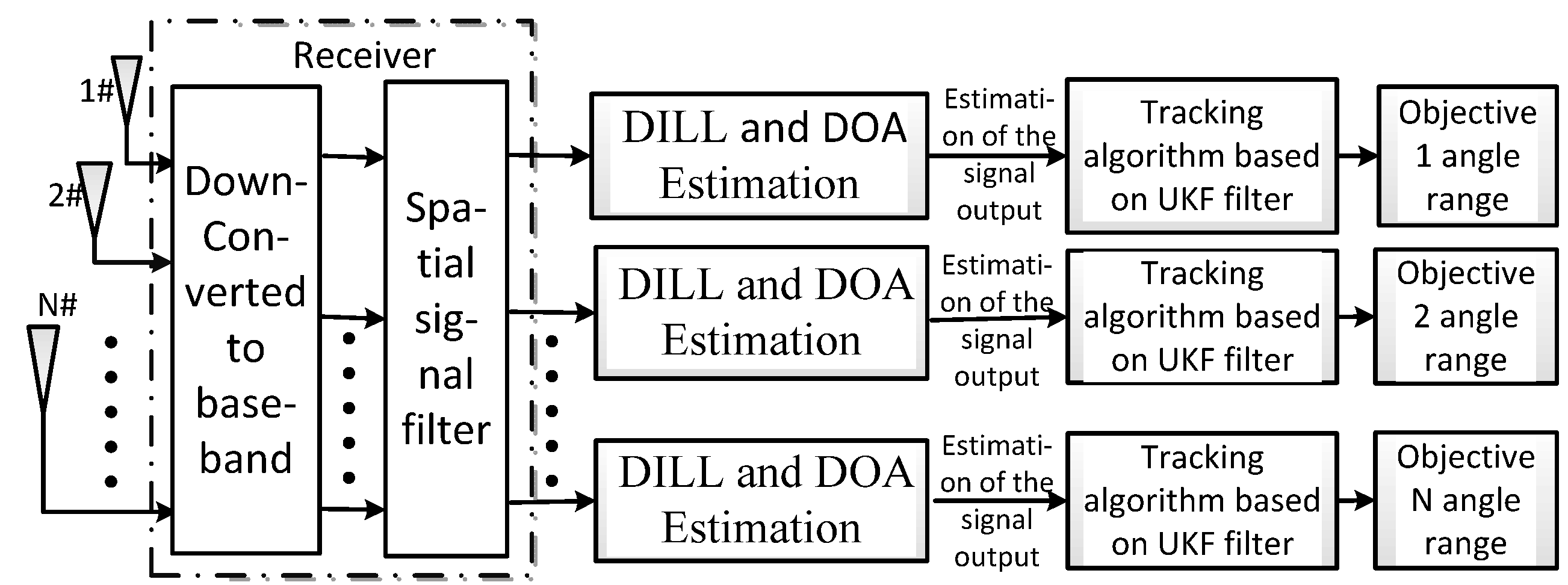
The system is constructed on the basis of DILL structure like shown in the
Figure 1. The front-end receiver carries space sampling of different DOA signals and then transforms them into baseband signals by down-conversion. The signals are spatially filtered in the filter rejector to judge, recognize the users’ signals and restrain some noises. The signal received by the antenna is transmitted to the DOA estimator and used to estimate the DOA information. Finally, the estimating signals are processed by the UKF algorithm and the state distribution of the exact approximated signals is realized by recursion Bayes estimation. We can attain many approximations of the actual values, improving the update processing and tracking efficiency and accuracy to make the system more stable and efficient.
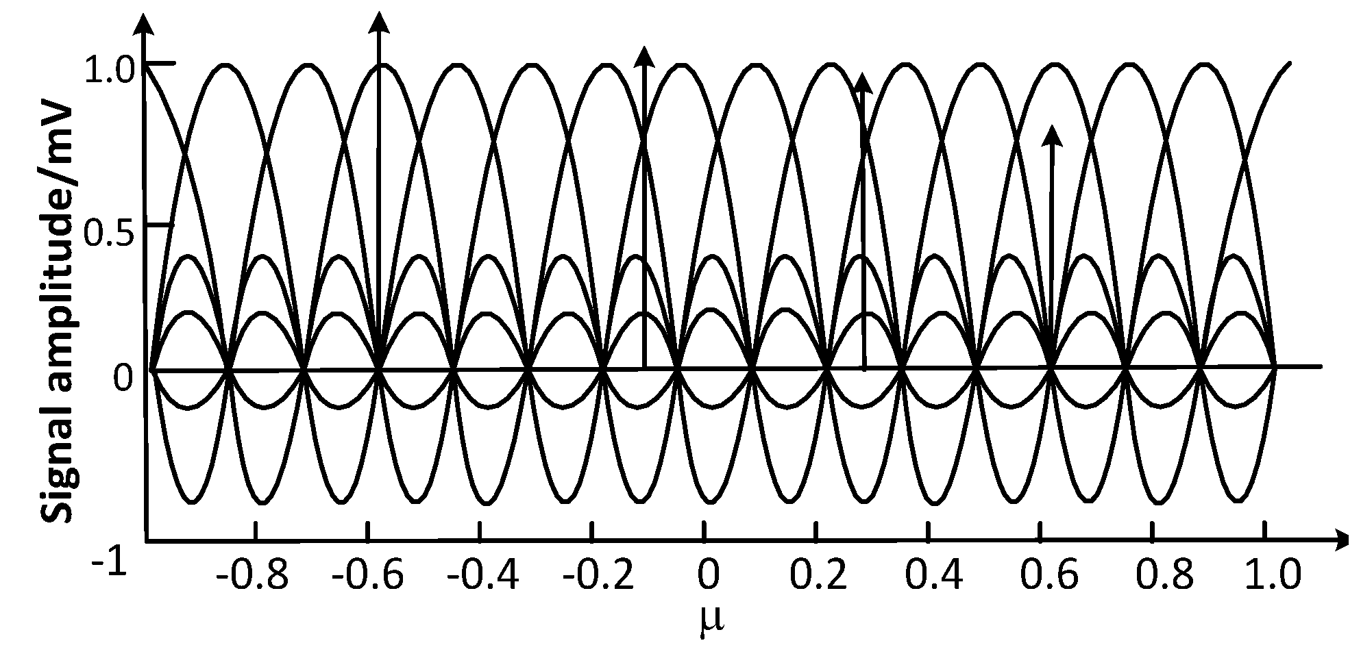
In the tracking model, the spatial signal filter is a beam space matrix made up of a baseband low-pass filter and a group of orthogonal weighing coefficients. The scene of judge original signals by the beam space matrix is shown in
Figure 2, where the abscissa axis denotes the multiple orthogonal beam space confined to 0~360°. A half beam width of the adjacent two beams is overlapped and we call it the power beam device. We select the baseband signals by passing different power beam devices. If we can get a relatively large power output, this implies that the signal is between the two space angles formed by the power beam device. Then we can attain the distribution interval of the signal DOA and further can judge and recognize the distribution of the mobile signal source DOA, providing the initial data for the subsequent extract location in the DILL.
Figure 1.
Locating and tracking model.
Figure 1.
Locating and tracking model.
Figure 2.
Beam space matrix.
Figure 2.
Beam space matrix.
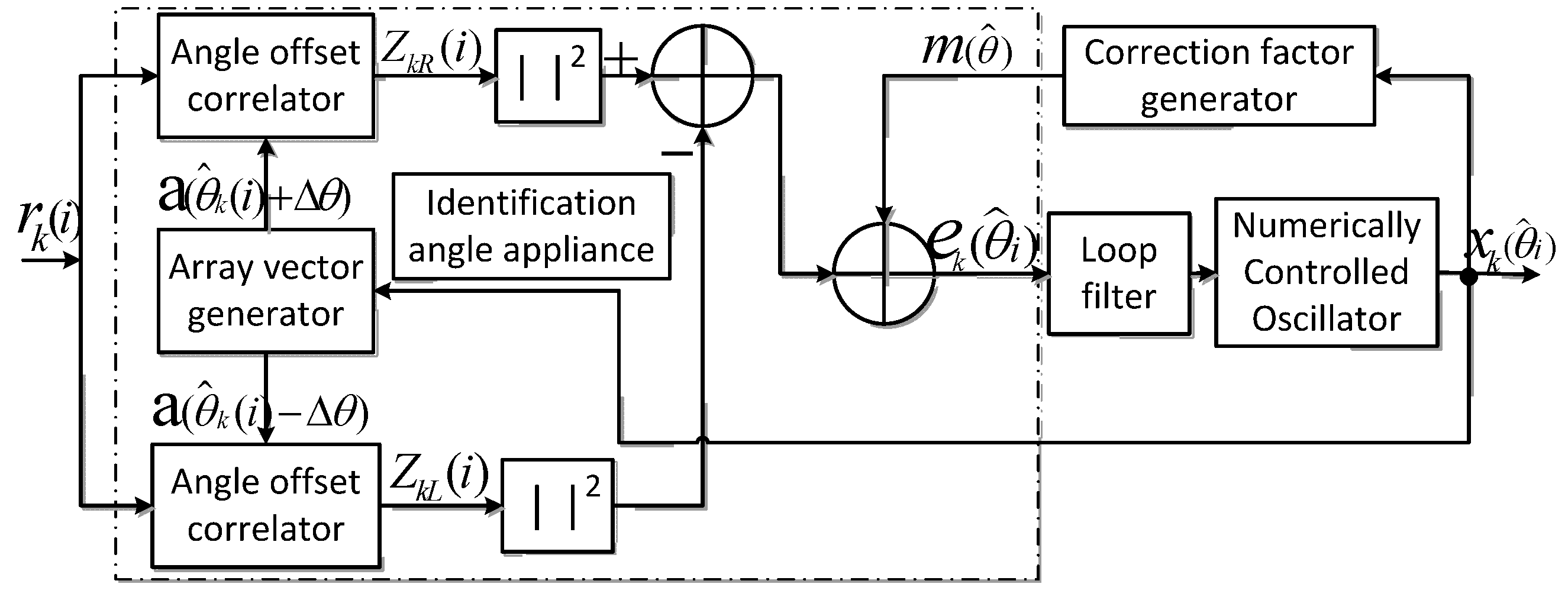
The tracking device of the DILL is similar to the phase-lock loop as it is modified from the later one. Like the tracking device of the phase-lock loop shown in
Figure 3, we replace the phase discriminator by the angle detector, the loop filter and digital-controlled oscillator. The angle detector is made up of two angular deflection correlators and an array vector generator to convert the related angles [
11,
12].
Figure 3.
Tracking device in the Direction Lock Loop (DILL).
Figure 3.
Tracking device in the Direction Lock Loop (DILL).
The rough estimated signal is transmitted to the angular detector in the DILL, and then we carry out angular deflection related operations of the and produced from the array vector generator. Then we update the error signal by subtracting the square of their molds to make a more exact approximation to the actual signal. We already did a DOA rough estimation of the signal source by spatial filter in the forepart process, making the receipt signal in the pull-in range in the estimation stage. In the whole feedback regulation process, we transmit the through a loop filter to control the digital-controlled oscillator, realizing the self-adapting real-time locating and tracking in the pull-in range.
The estimated signal by the DOA algorithm is not very exact due to the various Gaussian noises in the loop output signal and t the nonlinear influence on the communication system. At the same time, the number of estimated signals in the loop out is larger than the sampling number, so we should do more sampling to estimate filtering processing. The filtering based on the UKF can remove the nonlinear influence and restrain the noise efficiently, so this paper adopts the UKF filtering tracking algorithm to update the estimated signal value to get a more exact approximation of DOA.
3. DOA Estimation Algorithm Based on the DILL
Assume there are
K narrow-band signal reflected in aerial system with
N(
K <
N) array elements, the array element length is half a wavelength. The mathematical formula of the data vector transmitted in the aerial system at time
t is:
where
denotes the
vector of receipt signal,
denotes the DOA θ at time
t of the mobile target signal [
13]. To the simplicity, set
,
denotes the noise covariance vector of
K × 1 step, σ
2 is the noise covariance. Therefore, the sampled signal of the
K user can be expressed by:
If set the angular deflection produced by array vector generator is
, we then calculate the signal
and angular deflection signal
to output
and
respectively as:
where
is spatial correlation function and is expressed as follows:
,
denotes the noise offset. Like the tracking device in the DILL in
Figure 3, we extract the square of the molds of the signal from the correlator to get the error adjusting signal with biased estimation as:
where
is the angle discrimination function which determines the performance of the DOA. It can be denoted by:
can be expressed as:
To eliminate the impact of biased estimate, we subtract one correction factor
of the error signal
to attain the estimated error signal, and then we filter the radio-frequency component by loop filter and transmit the low-frequency signal to the digital-controlled oscillator to update the approximation of the DOA rather than the non-relevant correction factor
. As defined as
in [
14], we can get the modified non-relevant estimated signal as:
where
, the new estimate of the DOA at time of
i + 1 is
where
is the pulse response of the loop filter,
is the gain of the digital-controlled oscillator.
will be closed to the actual
infinitely in the repeatedly updates, making the evaluated error of DOA small enough to realize the location of DOA of the signal.
To analyze the performance of the DOA estimation, this paper defines the evaluated error of DOA at time of
i as:
By combination of (9) and (10), we can attain the evaluated error at time of
i + 1 as:
As the
changes with the value of
and closes to the actual direction angle
of the signal, their actual relationship has an influence on the system error and we define the offset error as:
In the process of tracking
by
, the error of estimation
decreases gradually. When
, we can know
while
is negative. Then we can get the value of
is:
Then we do
Z-transformation of equation (14) to attain the functional equation of DOA estimation in the domain of
Z:
where
is the
Z-transformation of the loop filter and the transfer function of the loop system is:
As the system is nonlinear that cannot adopt the model of Z-domain transformation in the linear system to carry state analysis, for the value of , we should do nonlinear filter processing to resample estimation to update the DOA data.
4. UKF filtering processing
In the section two, we attain the transfer function of the loop system by deduction. Since the system is non-linear, we cannot adopt linear system theory to analyze it. Furthermore, the DILL cannot eliminate the Gaussian noise effectively and has a relatively larger error to track with poor stability. In order to keep rapid, accurate tracking of mobile targets effectively, we adopt UKF filtering processing to filter the receipt signals, solving the defect of nonlinear distribution in the statistical property by using the UT transformation into Kalman filtering to attain the more accurate approximation of mean value and covariance of the signals.
After the Kth target signal source passes the DILL, the signal sampling points become more intensive as the orientation angle fluctuates around the . Set is sample output of Kth signal, for simplicity, this paper defines the signal as and the specific process of UKF filtering as follows:
Assume the state equation and measurement equation of the non-linear discrete system is respectively [
14]:
Where
is the state vector at the sampling instant of
while
is observation vector, and
is the noise vector. Then we estimate the
by UKF filtering.
(a) initialize the output variable
of DILL:
where
,
is state noise variance and measurement noise variance respectively. If
, then
(b) calculate the sampling pot value of the variable:
(c) estimate the state transformation:
where
is the state noise variance of the system.
(d) estimate the measurement transformation:
where
is the measurement noise variance of the system.
(e) calculate the cross covariance of state and measurement estimation:
(f) renew the weight gain and state:
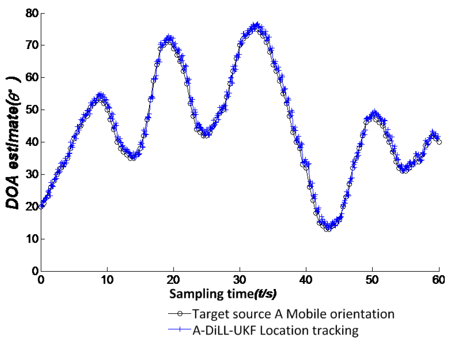
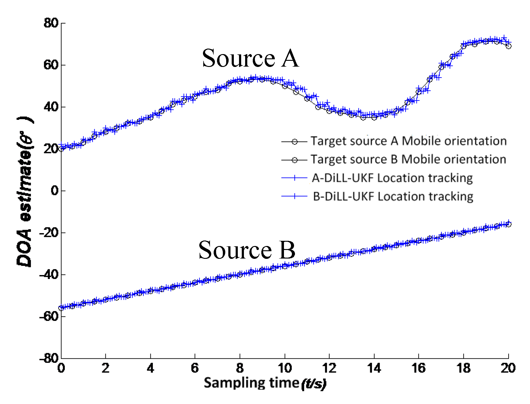
We can get the new angle predictor to reduce the error of non-linear estimation and restrain the noise effectively. By the above-mentioned iterative UKF filtering can we make a more accurate and reliable track of non-linear system.


