Article

An Efficient Vector Control Policy for EV-Hybrid Excited Permanent-Magnet Synchronous Motor

by
Nadia A. Elsonbaty
1,
Mohamed A. Enany
1 and
Mahmoud I. Hassanin
2,*
1
Electrical Power and Machines Department, Faculty of Engineering, Zagazig University, Zagazig 44511, Egypt
2
Electric Telecommunication Department, Faculty of Engineering, Egyptian Russian University, Bader city 11829, Egypt
*
Author to whom correspondence should be addressed.
World Electr. Veh. J. 2020, 11(2), 42; https://doi.org/10.3390/wevj11020042
Submission received: 25 April 2020 / Revised: 13 May 2020 / Accepted: 19 May 2020 / Published: 27 May 2020

Abstract

:
In this paper, a new control strategy for hybrid excited salient permanent-magnet synchronous motor (HEPMSM) is proposed, where both armature winding and DC field windings are located in the stator. The developed control strategy fulfills the required characteristics of the electric vehicles (EVs) and hybrid electric vehicles (HEVs) motors. A detailed mathematical model of the HEPMSM is presented. The field current (FC) is kept constant near its rated value for the high acceleration constant torque (CT) region. The conventional control usable method of reducing FC and reversing it on the motor performance characteristics through the constant power (CP) region is examined and evaluated. A proposed FC pattern is applied to three deferent operating modes of EV. High acceleration and wide stable constant power speed range without overdesign is the main target of this work. Based on the deduced optimum control pattern, the required EV-HEPMSM performance characteristics are developed. The required dq control armature, field currents as well as dq stator voltage components are provided for either current or voltage control technique availabilities. Simulation work is carried out on the commonly used method and on the proposed method. The obtained simulated characteristics effectively validate the target of the proposed steady-state presented analysis and pattern.

Nomenclature
V d s , V q s  the d- and q-axis stator voltage components
I d s , I q s  the d- and q-axis stator current components
I d , I q  d–q-axis armature inductance current components
  I d c , I q c  the d- and q-axis core resistance current components
ψ d , ψ q  the d- and q-axis flux linkage components
ψ p m , ψ f  the permanent-magnet and excitation flux linkages
p m  the permanent-magnet flux
ω r ,   p  the electrical angular velocity and pole pairs number.
L d   ,   L q  the d- and q-axis inductances
M s f  stator and excitation windings mutual inductance
V f   ,   I f  the excitation voltage and current.
R s   , R c  the stator winding and core resistances
E d   ,   E q  the d- and q-axis induced EMF components.
R f   ,   L f  the excitation winding resistance and inductance
T ,   N  the motor torque and mechanical speed
T r ,   P r  the motor rated torque and rated output power
N r , N b , N m  the mechanical rated, base, and maximum speed
V s   ,   ψ s  the stator voltage and flux linkage
φ s  the angle between stator voltage and q-axis
δ s  the angle between stator flux linkage and d-axis
ω s ,   S R  the electrical synchronous speed and speed ratio
I s r ,   K e  the rated stator current and machine constant
I q m a x  the maximum q-axis stator inductance current
T m   ,   T b  the motor maximum torque and motor base torque
E a , I a  the armature (stator) induced voltage and current
F c r  the rated field current
E a o , ψ d o  the no-load armature EMF and d-axis flux linkage

1. Introduction

The electric motor forms the central core of an electric vehicle. It has to fulfill requirements that are more severe than in other industrial sectors. The important required characteristics for electric vehicles (EVs) and hybrid electric vehicles (HEVs) motor drives are a wide speed constant power capability, low-speed high-torque hill-climbing, high torque density (Nm/kg), high power density (kW/kg), minimum size and mainly high operational efficiencies. Motors for vehicle application should, therefore, be designed with very thin laminations as far as the efficiency is concerned [1,2,3]. A high-performance wound field synchronous motor for EV drives fulfills all the aforementioned EVs requirements apart from the minimum size demand. Three proposed optimization modes of unity power factor, field-oriented control, and searched optimization mode were applied [1]. Some design concepts are particularly important such as the consistent weight-saving design, optimum safety concept, low drag coefficient body design, and low tire rolling resistance. A novel ac excited self-started axial flux synchronous motor (AFSM) for electric vehicles (EVs) was presented based on EV optimum profiles [2]. The permanent-magnet motors have an advantage over all other motors due to their high operational efficiency and high torque density (Nm/kg). Model-predictive current control (MPCC) is widely recognized as a high-performance control strategy of a permanent-magnet synchronous machine [4]. For the PMS hub motor (PMSHM), an optimal control strategy using the state feedback control method plus the grey wolf optimization (GWO) is presented [5]. For EV-PM motor drive, the rotor position is determined by applying senseless techniques [6,7]. However, at speeds beyond the base speed, the flux-weakening operating range of the permanent-magnet is limited and requires an additional stator negative current component. This would lower the efficiency and power factor which in turn has a direct impact on the sizing of the power converter [8]. To overcome this drawback, kinds of hybrid excitation synchronous motors (HEPMSM) have been proposed. HPMESM is provided by a combination of two excitation sources (coil excitation sources and permanent magnets (PMs)) which make this type of machine have many advantages as summarized as following [9,10].
  • Better flux-weakening capability in all modes.
  • Good alternative to PM alternators with power converter in generating mode
  • An easier achievement of high-speed operation with higher energy efficiency in motoring mode. The PMs provide the constant flux and the field current can boost or weaken the overall flux.
HEPMSM is classified into two main classes: series HEPMSM as shown in Figure 1 (DC coils excitation flux passes through PM) and parallels HEPMSM (DC coils excitation flux and the PM flux are in parallel paths). In series structures, the DC field winding flux crosses the PM flux resulting in high reluctance. Thus, the high field current is needed for flux-weakening causing high copper losses and the risk of PM demagnetization. In parallel structure, the PM flux and the DC field flux are superimposed in the air gap and the armature windings only as shown below [11,12].
The machine presented here belongs to the second class. Several HEPMSM control techniques have been presented. A novel adaptive control method based on combining the advantages of the hybrid excited synchronous machine and claw pole machine was presented [13]. In general, locating the excitation winding in the stator is preferable to avoid sliding contact problems such as slip ring maintenance and brush sparking [14]. Furthermore, hybrid excitation topologies and control strategies of stator permanent-magnet machines for DC power systems are discussed [15]. The authors of [16] introduced a parallel double excitation magnetic equivalent circuit model for unipolar HEPMSM. An optimized HEPMSM with a salient pole magnet shunting rotor is proposed to present a maximum torque control strategy with a zero d-axis current [17]. This paper presents an Efficient Control strategy for EV-HEPMSM and is organized as follows. An EV-based HEPMSM mathematical model is provided in Section 2. In Section 3, an EV practical ideal torque (power)–speed profile is provided. A proposed field current (FC) control with zero direct-axis (ZDAC) methodology over the two operating ranges (CT and CP) is presented in Section 4. Section 5, applies the EV motor optimum control concepts corresponding to the EV characteristics of Section 3. In Section 6, simulation work is carried out in which two flux-weakening algorithms are presented and compared with steady-state operating characteristics for evaluation. Finally, the conclusions are given in Section 7.

2. EV-Based HEPMSM Mathematical Model

Figure 2 illustrates the HEPMSM equivalent circuit [16], from which the following mathematical model is deduced.
The stator voltage equations can be written in synchronous d–q reference frame, as follows [18]
V d s = R s I d s + d d t ψ d ω r ψ q
V q s = R s I q s + d d t ψ q + ω r ψ d
where the flux linkage equation can be given below
ψ d = ψ p m + L d I d + M s f I f
ψ q = L q I q
So the stator voltage equations can be rewritten as follows
V d s = R s I d s + L d d d t I d + E d
V q s = R s I q s + L q d d t I q + E q
where
E d = ω r L q I q    
E q = ω r ( ψ p m + L d I d + M s f I f )                
The stator current equations can be written in synchronous dq reference frame as follows [12]
I d s = I d   + I d c = I d   + E d R c                    
I q s = I q   + I q c = I q   + E q R c    
So the stator voltage equations can be expressed as follows
[ V q s V d s V f ] = [ R s + s L q ω r L d R ω r   M s f R ω r L q R R s + s L d 0 0 0 R f + s L f ] [ I q I d I f ] + [ ω r   ψ P M R 0 0 ]
where s = d d t = 0 at steady-state,
R = 1 + R s R c    
Electromagnetic torque equation can be expressed as follows
T = 3 2   p   I q ( ψ p m + ψ f + ( L d L q ) I d   )          
where
ψ f = M s f I f
T is a sum of hybrid torque and a reluctance torque.

3. Practical Ideal Torque–Speed Profile of Traction Motor Drive for EV/HEV

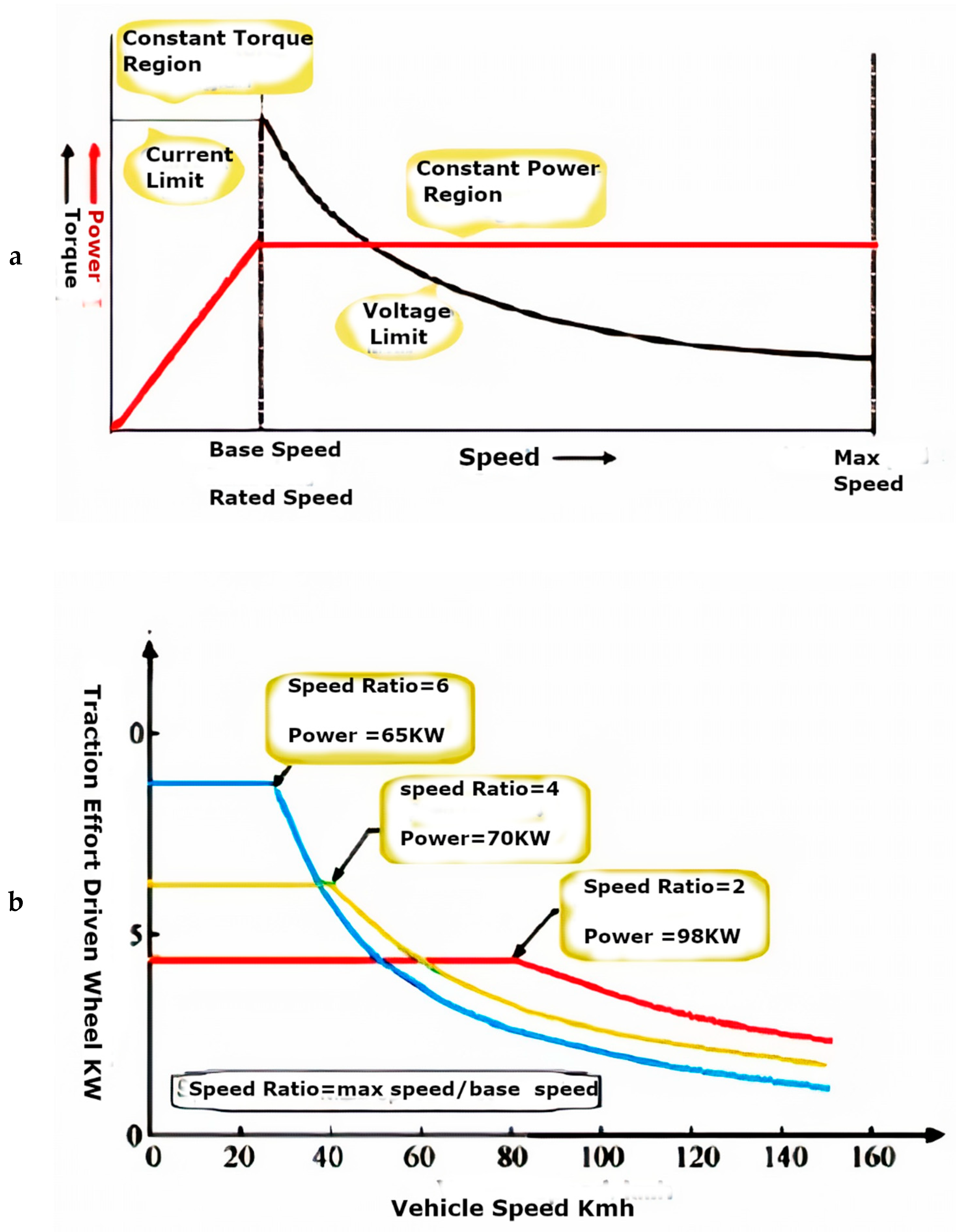
The development of compact, lightweight, high efficiency and proper torque–speed profile becomes crucial. A well-controlled electric motor drive has the torque–speed profile close to the ideal one as shown in Figure 3 [18]. The torque–speed profile of a well-controlled electric motor drive includes two distinguishable regions: constant torque and constant power. The corner speed is usually called base speed. At a given power rating and maximum speed, the lower base speed is resulted in a larger maximum torque. A term, speed ratio, is defined as the ratio of the maximum speed to the base speed [1,19,20].

4. Proposed FC Control with ZDAC Strategy

4.1. Constant Torque Region Control (CT)

Ideally but not practically the EV motor may operate directly in the constant power region for both motoring and regenerating regions. Alternatively, a high acceleration as possible is required to fulfill the required wide constant power speed range (CPSR) for EV. High acceleration is achieved by applying a ZDAC strategy which results in maximum stator current with minimum armature copper losses. High constant field current (95% of its rated value) is applied to strengthen the PM flux at the high-torque low-speed region. Base speed is a common factor between increasing CPSR and inviting over design problems. If a PMSM with the same CPSR as the original motor was to be used where the CT region extends to rated speed, it would cause a remarkable over design. Thus, control over the CP region on which the field current varies to implement wide CPSR is carried out first. Based on resulted performance characteristics, the complete EV-HPMSM profile characteristics is given in Section 5.
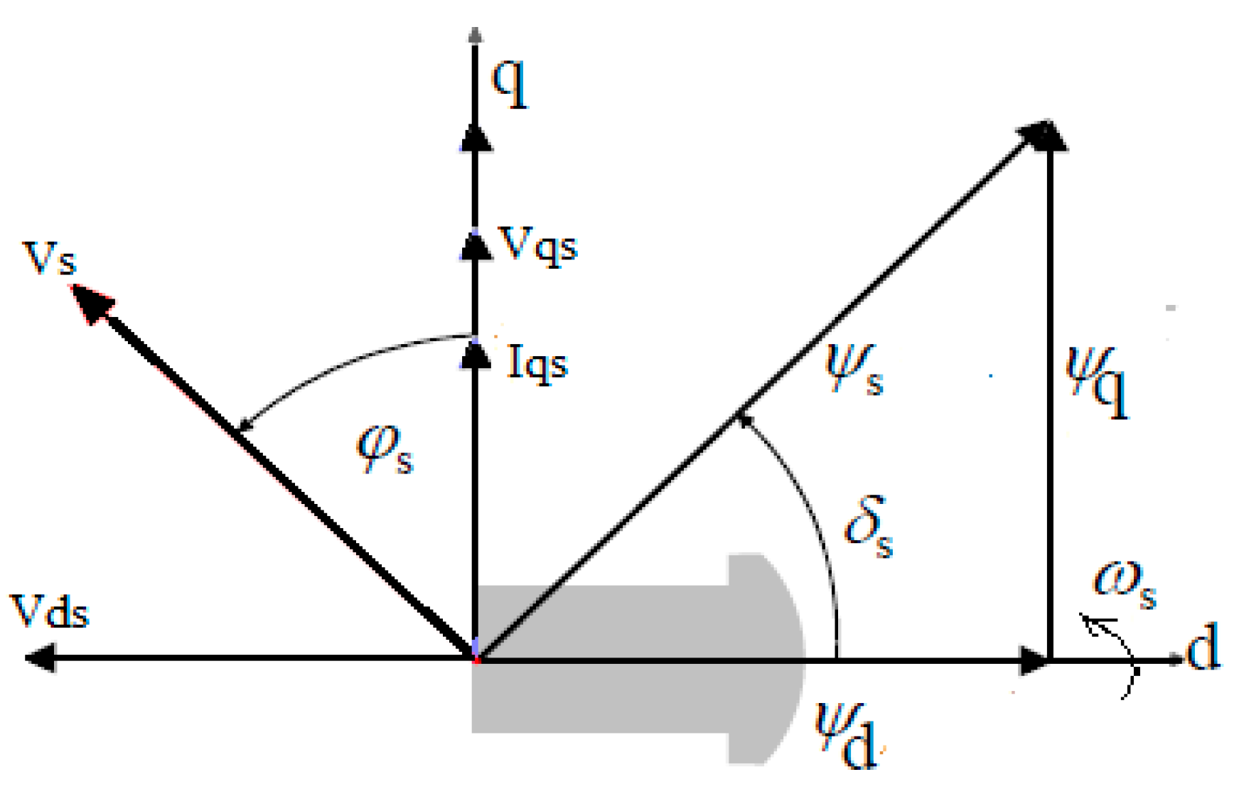
To produce maximum starting constant torque up to base speed, ZDAC strategy (Id = 0) as shown in Figure 4 is applied where rotor speed, N ≤ Nb where Nb is lower than rated speed Nr. Maximum torque is defined by the constantly rated stator current limit (Equation (19)) with detailed characteristic is given in Section 5. Within this speed range, both PM and constant excitation field fluxes produce constant flux. They are superimposed in the air gap and armature winding. The field current is nearly at its rated value (95% of rated value) to create 30% of the PM flux for field strengthening. If the iron loss equivalent resistance (Rc > 10Rs), it can be neglected [11].

4.2. Proposed Flux-Weakening Control (CP)

Unlike CT, CP operation is characterized by higher rotor speed (beyond base speed) where N > Nb. To do this the field current must be adjustable. It may be reduced or even reversed to weaken the flux. Previous researches apply bidirectional field current starting with PM flux aiding (described by +ve) then reverses its direction to weaken the flux (described by −ve) passing through zero value as shown in Figure 5a. A reduced +ve linear field current is proposed in this paper. The two fields of PM and FC are superimposed as shown in Figure 5b to avoid the demagnetization effect.
Figure 6, Figure 7, Figure 8, Figure 9, Figure 10, Figure 11, Figure 12 and Figure 13 illustrate the field current magnitude and direction effect on HEPMSM (see Appendix A) characteristics. The conventional control method applies reduced positively descending FC down to 0 then to negative ascending to its −ve rated value. The proposed control strategy applies positively descending to zero. The control algorithm is based on the mathematical model given in Section 2 with the constraints given by Equations (15) and (16). For proposed unidirectional electric field current control ( + ve   FC ) over the CPSR, the computational algorithm is based on the following constraints;
{ FC |   CP . st = FC   max =   FC |   CT . end                           FC   min = 0                                   and ,           N min |   CP =   N b           N max |   CP =   N FC |   0             and                 FC = 6 4   N + 1.26  
Equation (15) indicates that the CP region starts with maximum applied FC value equals to the end value of the CT region, while ends with zero FC leaving PM excitation on its own. Thus FC |   CP . st = FC   max = FC |   CT   end , where FC   min = 0 belongs to maximum motor speed as given by N max |   CP =   N FC |   0 and so on. The field current decreases slowly with the speed increase in linear form as given by the FC equation obtained through the fitting process. Within the computational program, the field current was reduced by equal regular steps based on the considered speed range such that it vanishes at the specified maximum speed. The field current–speed equation is given for control implementation by which the duty cycle ratio of the control chopper in the field circuit can be easily obtained. Although traditional control methods apply reduced and reversed non-linear FC (+ve, 0, −ve form). However, for fair comparison reduced and reversed but linear FC control is given here due to the constraints of Equation (16). For the traditional bidirectional electric field current control (+ve and −ve FC) over the CPSR, the computational algorithm is based on the following constraints:
{ FC |   CP . st = FC |     CP , min . =   FC |   CT . end     FC   max = FC |   r                                                                                   where   FC r   is   the   reversed   rated   FC   value .     N min |   CP =   N b       N maxx |   CP =   N b |   FCr     and       FC = 1.5 3   N + 1.7  
It can be noticed from Equation (16) and Figure 5a that FC |     CP , min . = FC |   CT . end must not equal zero, but having the PM flux aiding direction for the high acceleration torque required for EV. Its value depends on the applied control method. For the field-weakening operating region, the following constraints in terms of dq current and voltage are considered as follows.
As the speed increases the induced EMF increases but the flux decreases, however, both of stator current and voltage are constrained up to their maximum values for thermal consideration of both motor and converter as given by Equations (17) and (18), respectively.
I d 2 + I q 2         2       I a
where
v d 2 + v q 2         2       v a
As the EV motor CP region requires the torque to be inversely proportional with speed, then
T = T m a x N b N   w h e r e   N   N b
From which
I q =                         2 T                         3 p   ( ψ p m + ψ f )
Recall Equation (14)
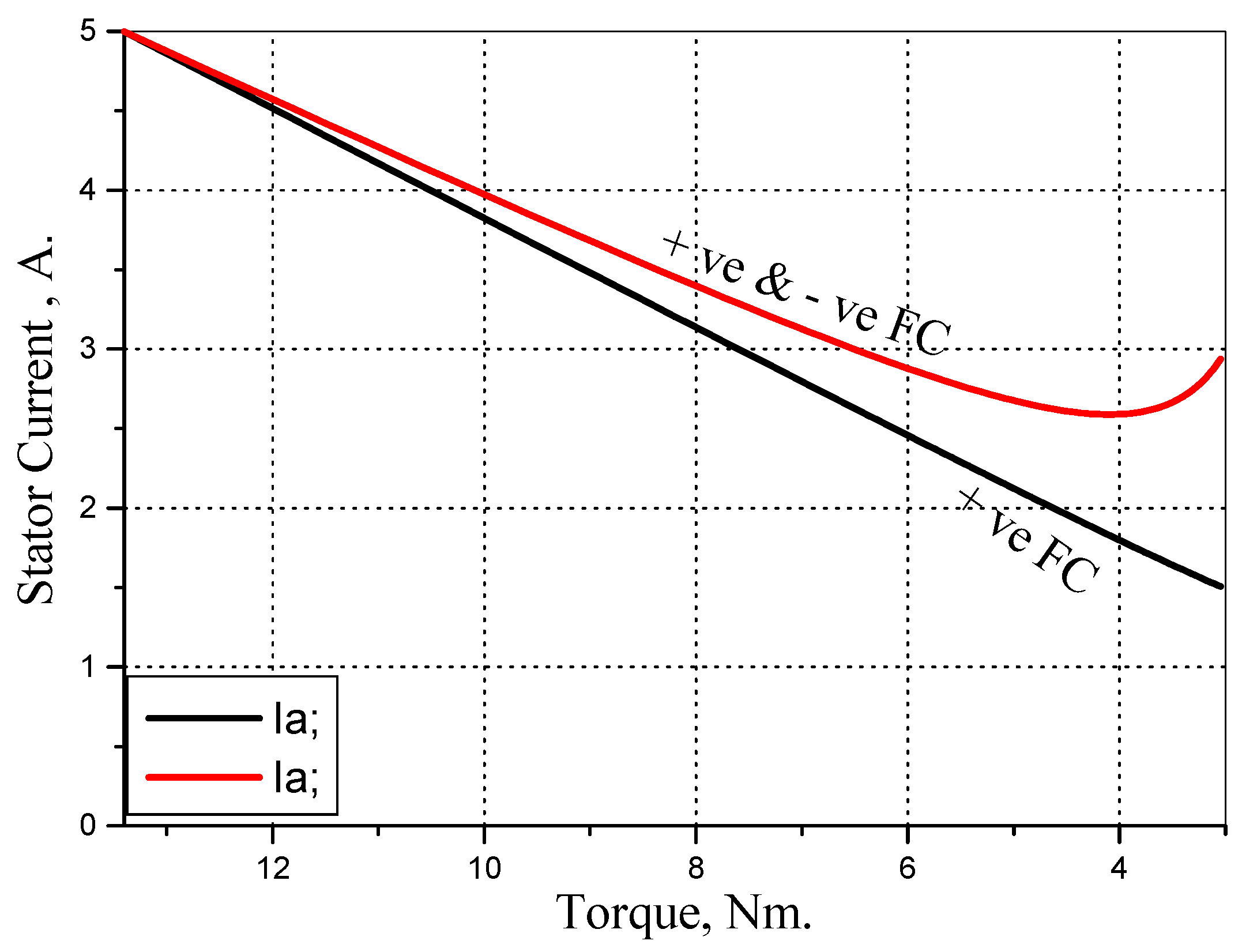
As I f varies linearly with speed, I q varies in correspondence to torque variation. With known T ,   I q and I f with ZDAC, all performance characteristics over the CP region are obtained. Figure 6 shows that the positive field remarkably extends the CP operating speed range, where reduced and reversed FC control strategy with ZDAC, results in a remarkable lower speed. The important property of linear stator current–torque relationship for control, simplicity is achieved with +ve FC control strategy but not with −ve FC as shown in Figure 7.
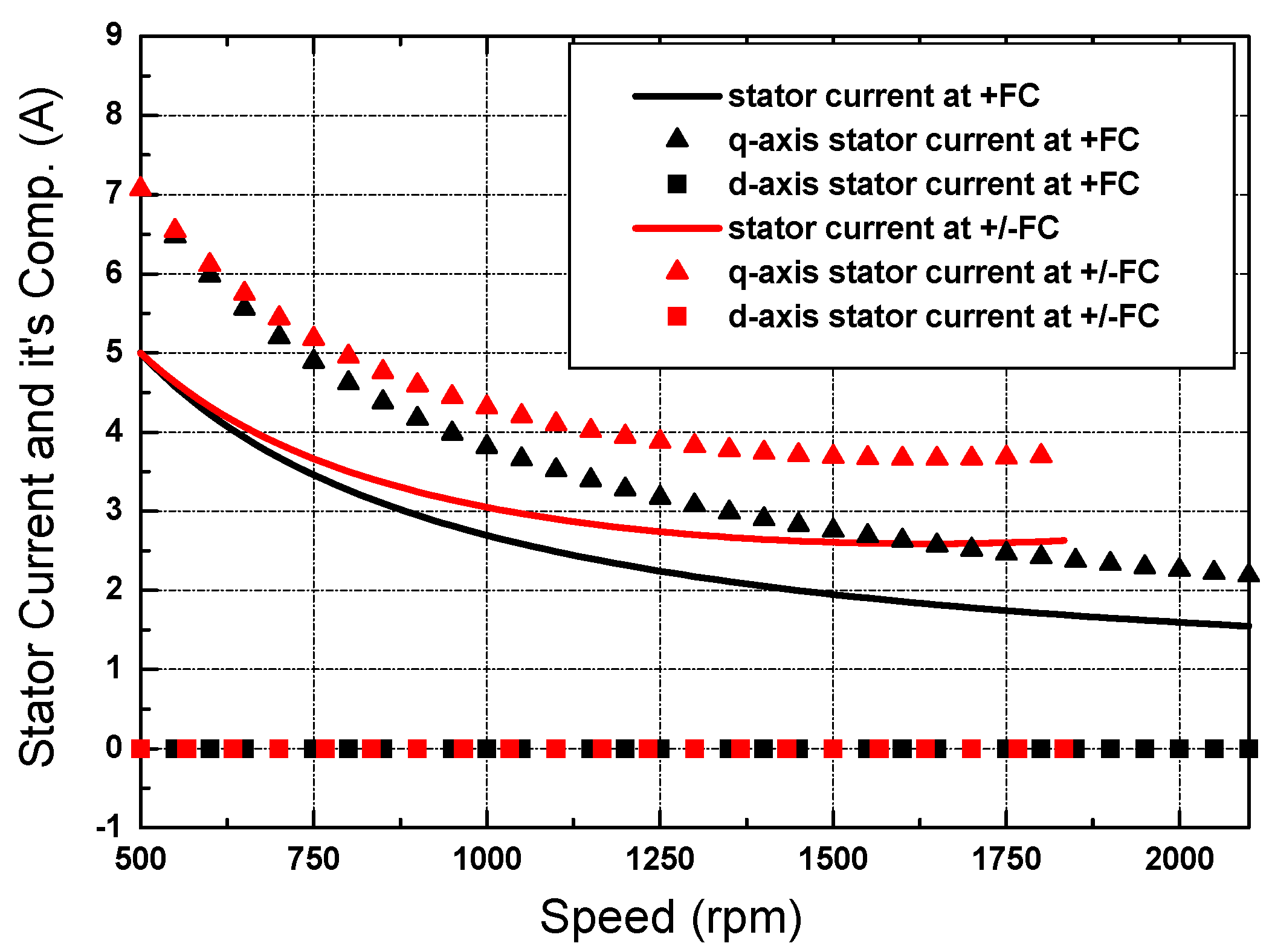
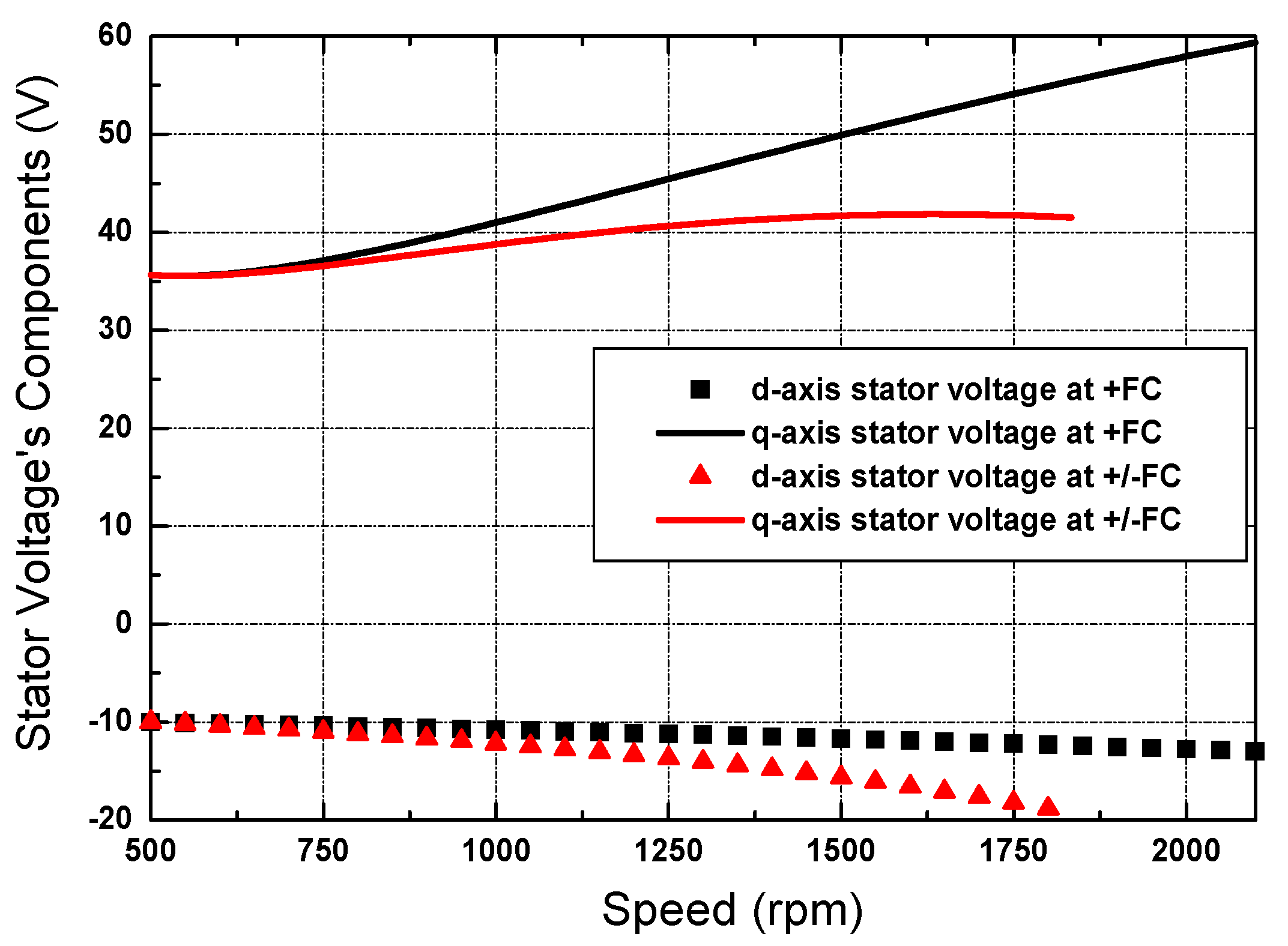
Figure 8 illustrates the torque, output power, and input power as affected by FC magnitude and direction versus speed for CPSR. It can be seen that +ve FC remarkably extends the flux-weakening region with maintaining constant power at less input power. Both stator voltage and back emf at +FC has a near-linear relationship with speed as shown in Figure 9. Thus improved stability at less d v d t stress will be obtained. The dq voltage’s and current’s components are provided for current or voltage control strategies as shown in Figure 10; Figure 11, respectively. Figure 10 clearly shows the q-axis current proportionality with 1/ ω r . Constant reactive voltage drop E d (Equation (7)) and consequently   V ds , given in Figure 11 prove the validity of the applied +ve FC with the ZDCA algorithm.
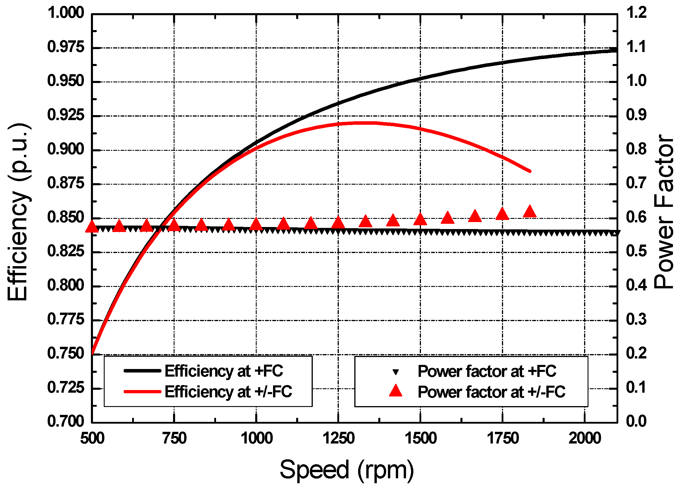
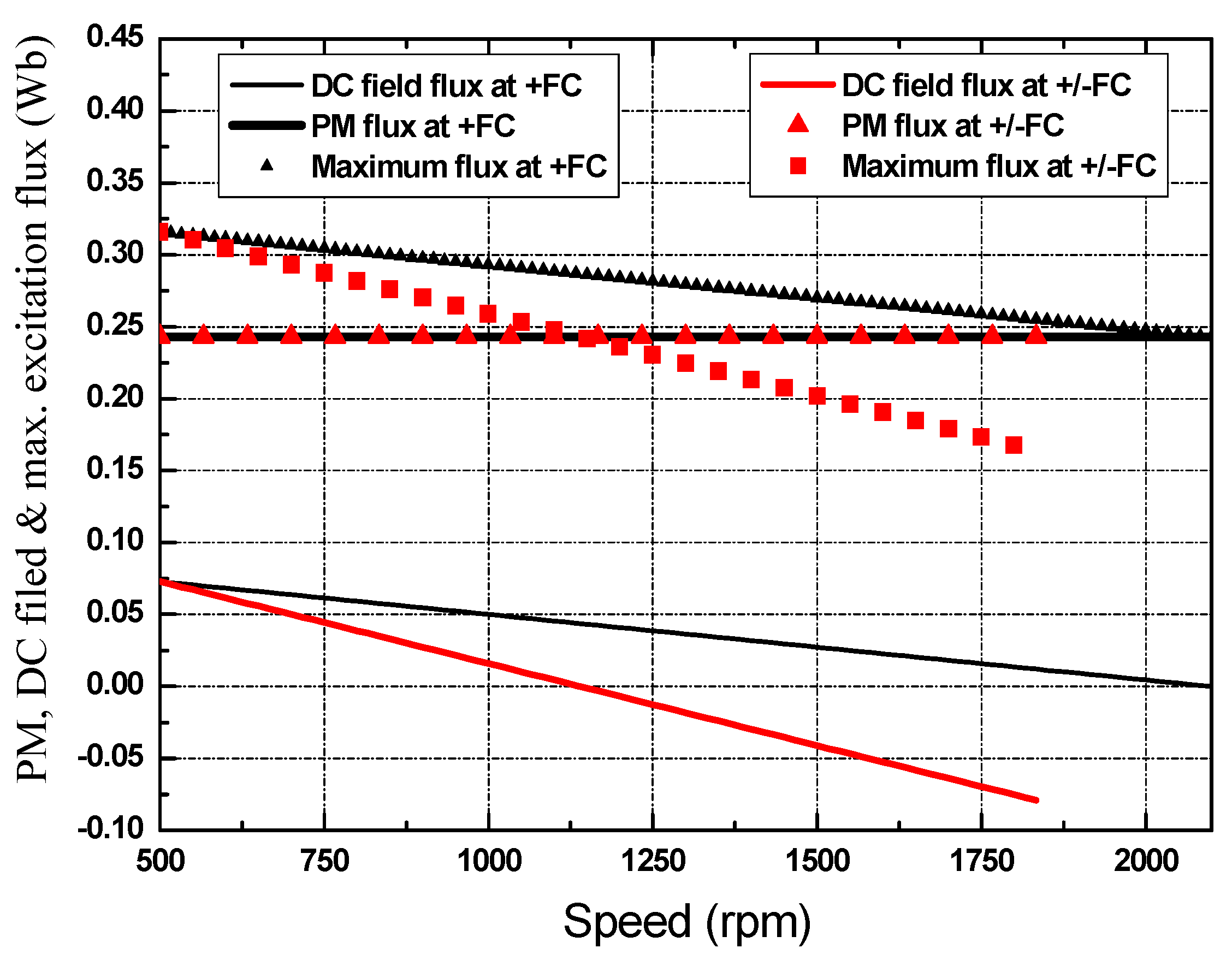
Figure 12 Further depicts the efficiency improvement with the proposed system. The three HPMSM fluxes   of     ψ pm ,   ψ f and ψ max at +ve FC technique as compared with +ve/−ve FC are shown in Figure 13.

5. EV Motor Optimum Control Strategies

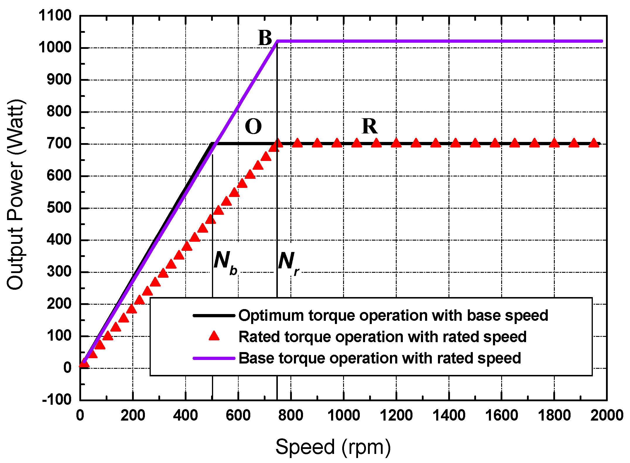
Proper EV motor control requires implementing Figure 3 characteristics on a usable motor. The operating mode at base speed has been chosen as the standard reference, with the electrical and mechanical quantities all being held at their nominal value. Non-reversed positive field current has proven to be an optimum control FC overall the all required EV speed operating range. Low constant power speed range (CPSR) can be a limiting factor, and in certain situations, it can force the designer to select a motor drive with power more than the EV needs (overdesign). This results in an overdesigned drive train [21,22]. As the speed ratio increases, the translation system from shaft to the wheel decreases and so its cost. The base speed (in rpm) at point O in Figure 14 is determined as follows:
N b = 30 π   E a 0 ψ d o   K e
The speed ratio is determined as follows
S R = N m a x N b
The maximum torque for the acceleration region (O) in Figure 16 is determined by substituting Id = 0 (ZDAC) into Equation (13), as given by Equation (19).
T m = 3 2   p   I q m a x ( ψ p m + ψ f )    
where
I q m a x = 2 I s r
I s r is the rated stator current, thus constant rated armature current will have resulted over the CT operating range. Substituting into Equations (5)–(8), all required characteristics are obtained as shown in the following figures. To verify this phenomenon, three operating patterns are proposed and depicted in Figure 14, Figure 15 and Figure 16.
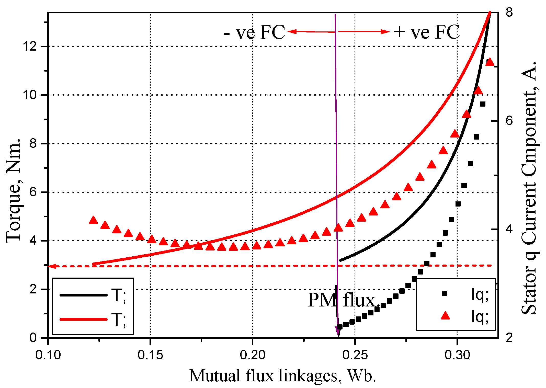
The effect of the two torque producing components given by the stator mutual flux (produced by the PMs and the field winding current variation) and the stator q current component on the produced torque is self-explained as shown in Figure 17. CT operating up rated speed at the same load requires a higher than the motor rated power due to the operating speed difference.

6. Modeling and Simulation

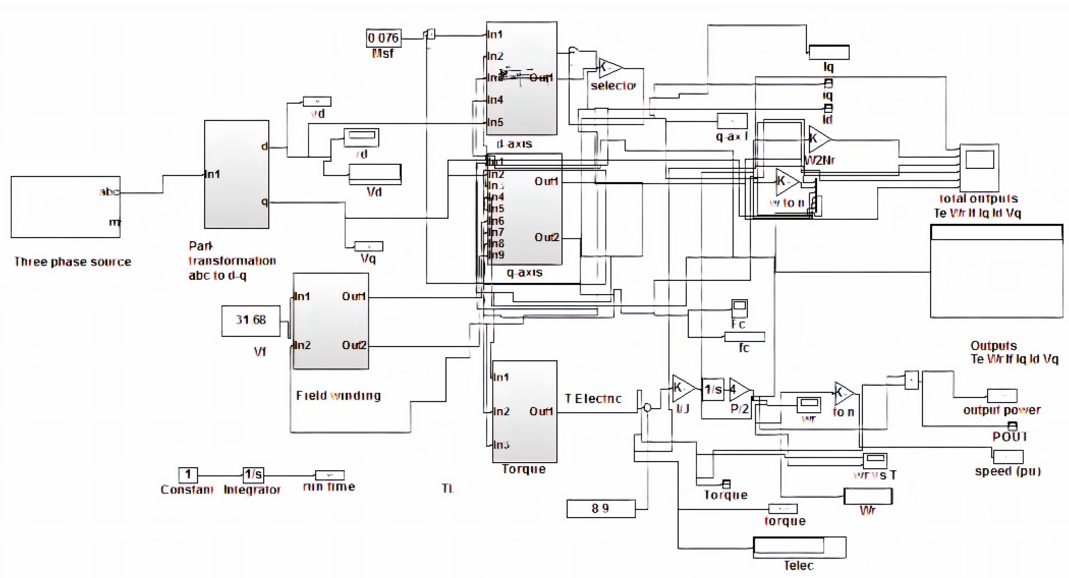
To verify the validation of the optimum torque operation applying base speed rather than rated one, the driving system simulating a model of HEPMSM is developed by using MATLAB/SIMULINK as shown in Figure 18. The two flux-weakening patterns defined by maximum torque at base speed and rated torque at rated speed are presented and compared with steady-state operating characteristics.
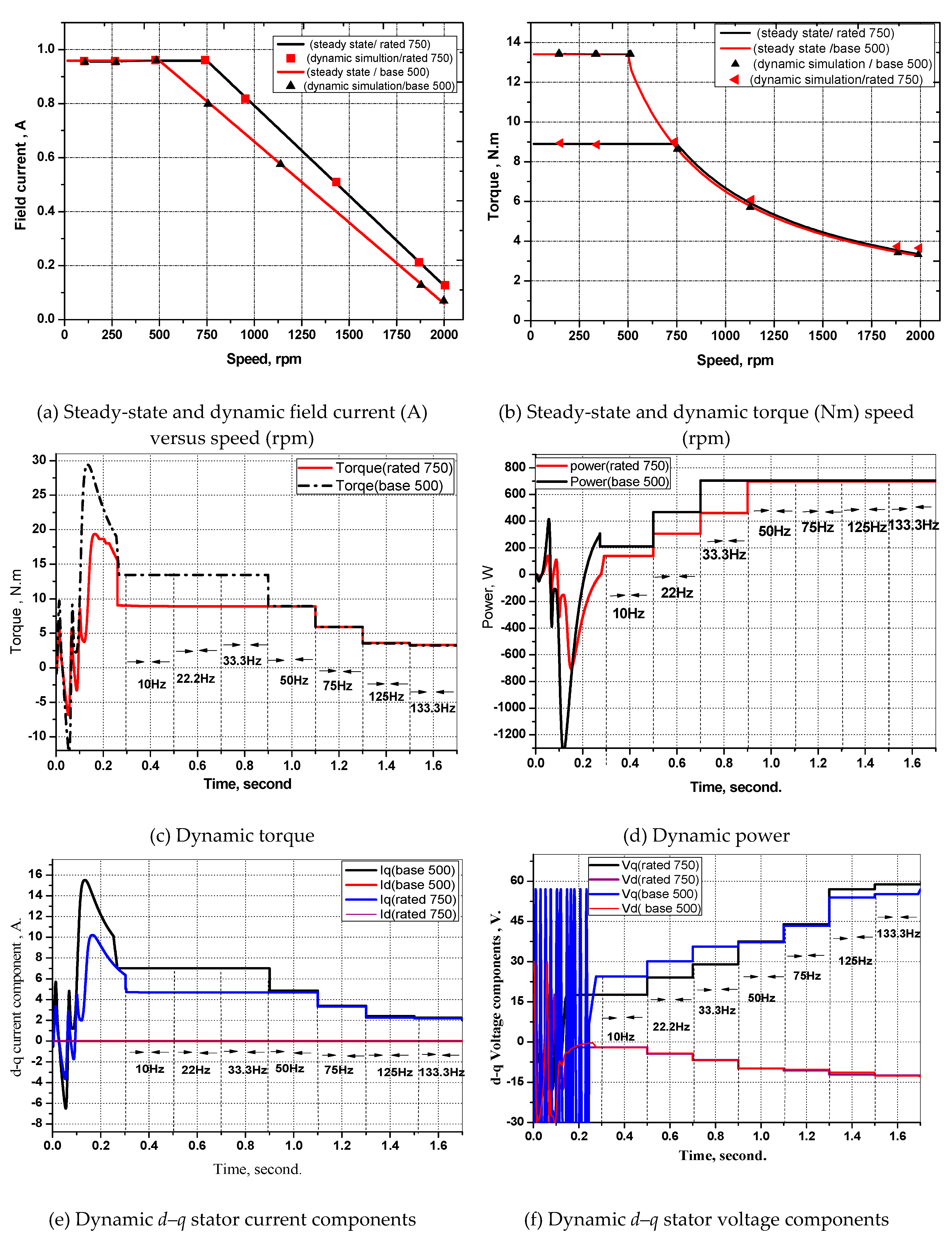
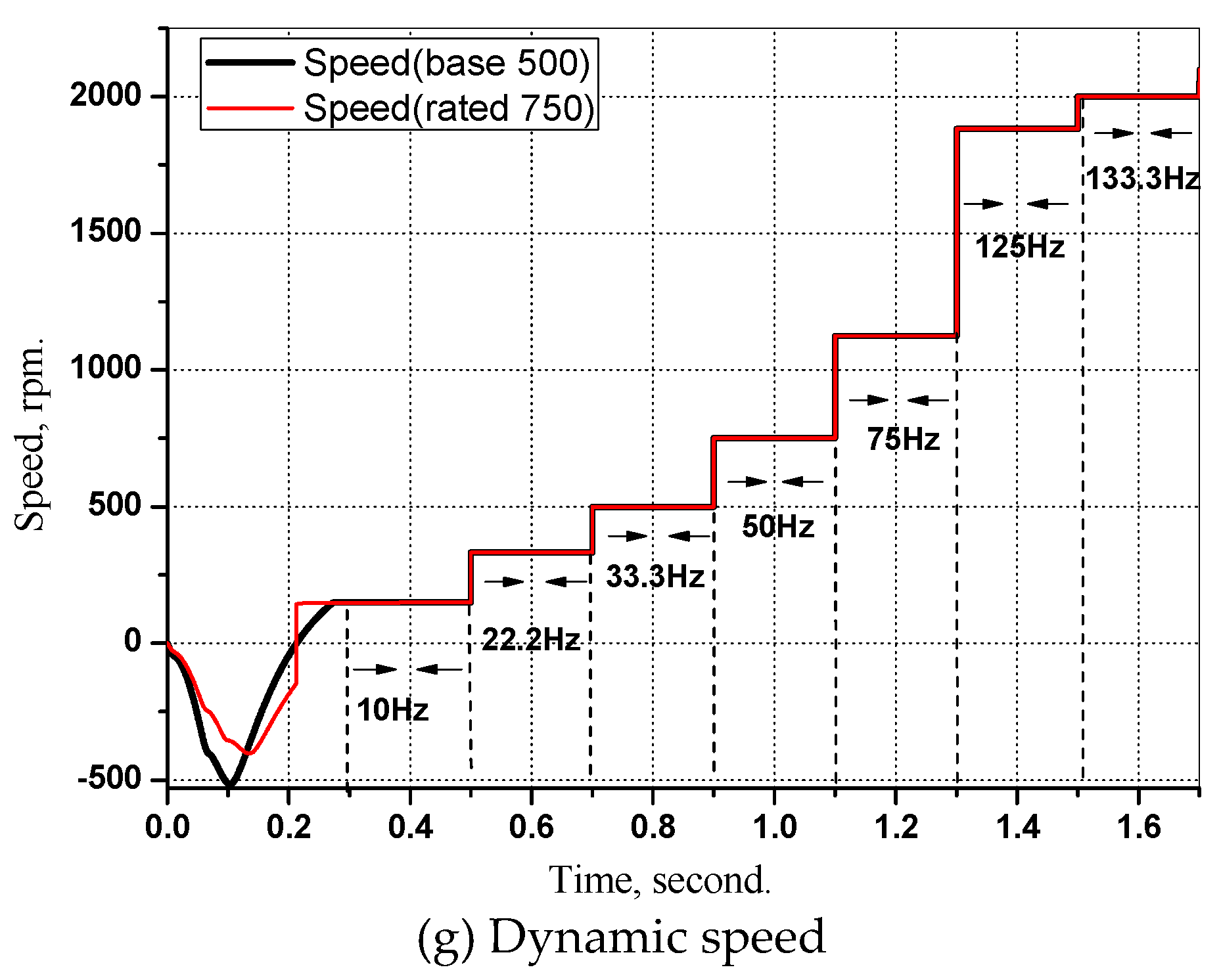
Steady-state performance characteristics and simulation results for field current and torque are presented. Both systems apply the same proposed control patterns of ZDAC and unidirectional (+ve) linear reduced field current at the base and rated speeds for fair comparison as shown in Figure 19a. Figure 19b clearly shows that reduced speed enables much higher acceleration torque than rated torque at rated speed to keep the power constant at its rated value. Any higher acceleration torque at rated speed brings in overdesign problems as given in Figure 15.

7. Conclusions

Many pieces of research apply nonlinear reversed excitation methods for HEPSM control. The field current reverses its direction from positive to a negative value to extend the CPSR at the expense of decreased efficiency due to the increased copper losses. This paper proposes an optimum control strategy that fulfills the favorite required EV motor characteristics. MTPA using maximum torque at base speed (ZDAC) results in high acceleration at high efficiency over the CT region with constant rated stator and field current. CPSR is much more efficient than that with reversed current (nonlinear flux). The paper confirms that the operation of EVs motor at rated torque and rated speed is not convenient to fulfill EV requirement unless overdesigned. The presented proposed technique of non-reversed field current under ZDAC control exhibits an important linear torque-armature current with linear field current–speed relationships. This greatly simplifies the control technique and improves motor stability. An extended speed ratio of 4:1 is achieved over the CPSR using the proposed strategy. Stator current and voltage dq components are provided to enable either current or voltage control system’s achievement. The MATLAB Simulink results effectively validate the proposed optimum control concepts and targets.

Author Contributions

N.A.E. and M.A.E. conceived of the presented idea. M.I.H. developed the theory and performed the computations on the selected motor. M.I.H. and M.A.E. verified the steady state model. N.A.E. encouraged M.I.H. to do the simulation works and supervised the validation of this work. All authors discussed the results and contributed to the final manuscript. All authors have read and agreed to the published version of the manuscript.

Funding

This research received no external funding.

Acknowledgments

Financial support for this study was provided by the authors’ own expense.

Conflicts of Interest

The authors declare no conflict of interest.

Appendix A

Understudy motor parameters [7].
p 4
N b 500 rpm
T b 13 N.m
I s r 5 A
I f r 1 A
P r 700 Watt
R s 2.7 ohm
R f 33 ohm
L d 38 mH
L q 27 mH
L f 0.57 H
M s f 76 mH
p m 0.243 Wb

References

  1. Elsonbaty, N.A. High Performance Wound Field Synchronous Motor for EV Drives. Sci. Bull. 2003, 38, 497–513. [Google Scholar]
  2. Elsonbaty, N.A. A Novel AC Excited Axial Flux Synchronous Motor for Electric Vehicles. Alexandria Eng. J. 2003, 42, 209–217. [Google Scholar]
  3. Villani, M. High performance electrical motors for automotive applications—Status and future of motors with low cost permanent magnets. In Proceedings of the WMM-18–8th International Conference Magnetism and Metallurgy, Dresden, Germany, 12–14 June 2018. [Google Scholar]
  4. Zhang, Y.; Xu, D.; Liu, J.; Gao, S.; Xu, W. Performance Improvement of Model-Predictive Current Control of Permanent Magnet Synchronous Motor Drives. IEEE Trans. Ind. Appl. 2017, 53, 3683–3695. [Google Scholar] [CrossRef]
  5. Sun, X.; Hu, C.; Lei, G.; Guo, Y.; Zhu, J. State Feedback Control for a PM Hub Motor Based on Grey Wolf Optimization Algorithm. IEEE Trans. Power Electr. 2019. [Google Scholar] [CrossRef]
  6. Sun, X.; Hu, C.; Lei, G.; Yang, Z.; Guo, Y.; Zhu, J. Speed Sensorless Control of SPMSM Drives for EVs With a Binary Search Algorithm-Based Phase-Locked Loop. IEEE Trans. Veh. Technol. 2020. [Google Scholar] [CrossRef]
  7. Sun, X.; Junhao, C.; Gang, L.; Youguang, G.; Jianguo, Z. Speed Sensorless Control for Permanent Magnet Synchronous Motors Based on Finite Position Set. IEEE Trans. Ind. Electr. 2020. [Google Scholar] [CrossRef]
  8. Huynh, T.A.; Hsieh, M. Performance Analysis of Permanent Magnet Motors for Electric Vehicles (EV) Traction Considering Driving Cycles. Energies 2018, 11, 1385. [Google Scholar] [CrossRef] [Green Version]
  9. Asfirane, S.; Hlioui, S.; Amara, Y.; Gabsi, M. Study of a Hybrid Excitation Synchronous Machine: Modeling and Experimental Validation. Math. Comput. Appl. 2019, 24, 34. [Google Scholar] [CrossRef] [Green Version]
  10. Hlioui, S.; Amara, Y.; Hoang, E.; Lecrivain, M.; Gabsi, M. Overview of hybrid excitation synchronous machines technology. In Proceedings of the International Conference on Electrical Engineering and Software Applications (ICEESA), Hammamet, Tunisia, 21–23 March 2013; pp. 1–10. [Google Scholar]
  11. Yildiriz, E.; Önbilgin, G. Design studies of axial flux hybrid excitation synchronous machine with magnetic bridge. In Proceedings of the 8th International Conference on Electrical and Electronics Engineering (ELECO), Bursa, Turkey, 28–30 November 2013; pp. 234–237. [Google Scholar]
  12. Amara, Y.; Vido, L.; Gabsi, M.; Hoang, E.; Ahmed, A.; Lecrivain, M. Hybrid Excitation Synchronous Machines: Energy-Efficient Solution for Vehicles Propulsion. IEEE Trans. Veh. Technol. 2009, 58, 2137–2149. [Google Scholar] [CrossRef]
  13. Zhang, Y.; Huang, Q.; Huang, M.; Decker, D.; Qing, Y. Design and Experimental Verification of Adaptive Speed Region Control for Hybrid Excitation Claw-Pole Synchronous Machine. Progress Electromagn. Res. C 2018, 88, 195–205. [Google Scholar]
  14. Hendijanizadeh, M.; Sharkh, S.M.; Qazalbash, A.A. Comparison of PM and Hybrid Excited Machines for Marine Vessel Hybrid-Electric Propulsion. In Proceedings of the 2018 XIII International Conference on Electrical Machines (ICEM), Alexandroupoli, Greece, 3–6 September 2018. [Google Scholar]
  15. Wang, Y.; Deng, Z. Hybrid Excitation Topologies and Control Strategies of Stator Permanent Magnet Machines for DC Power System. IEEE Trans. Ind. Electr. 2012, 59, 4601–4616. [Google Scholar] [CrossRef]
  16. Kupiec, E.; Przyborowski, W. Magnetic equivalent circuit model for unipolar hybrid excitation synchronous machine. Arch. Electr. Eng. 2015, 64, 107–117. [Google Scholar] [CrossRef]
  17. Zhang, Z.; Liu, Y.; Tian, B.; Wang, W. Investigation and implementation of a new hybrid excitation synchronous machine drive system. IET Electr. Power Appl. 2017, 11, 487–494. [Google Scholar] [CrossRef]
  18. Mohammadi, A.; Trovão, P.; Dubois, R. Hybridisation ratio for hybrid excitation synchronous motors in electric vehicles with enhanced performance. IET Electr. Syst. Transp. J. 2017, 8, 12–19. [Google Scholar] [CrossRef]
  19. Wang, W.J.; Zhang, Z.R. Maximum torque control of hybrid excitation synchronous machine drives based on field current self-optimizing method. In Proceedings of the IECON 2013, Vienna, Austria, 10–13 November 2013; pp. 2977–2982. [Google Scholar]
  20. Safi, S.; SDT Drive Technology. Alternative Motor Technologies forTraction Drives of Hybrid and Electric Vehicles. Available online: https://assets.markallengroup.com/article-images/47910/DOWNLOAD%20THE%20FULL%20PAPER%20by%20Dr%20Sab%20Safi%20of%20SDT%20Drives.pdf (accessed on 18 February 2020).
  21. Borocci, G.; Capponi, F.G.; Donato, G.D.; Caricchi, F. Closed-loop flux-weakening control of hybrid-excitation synchronous machine drives. IEEE Trans. Ind. Appl. 2017, 53, 1116–1126. [Google Scholar] [CrossRef]
  22. Shinnaka, S. New optimal current control methods for energy-efficient and wide speed-range operation of hybrid-field synchronous motor. IEEE Trans. Ind. Electr. 2007, 54, 2443–2450. [Google Scholar] [CrossRef]
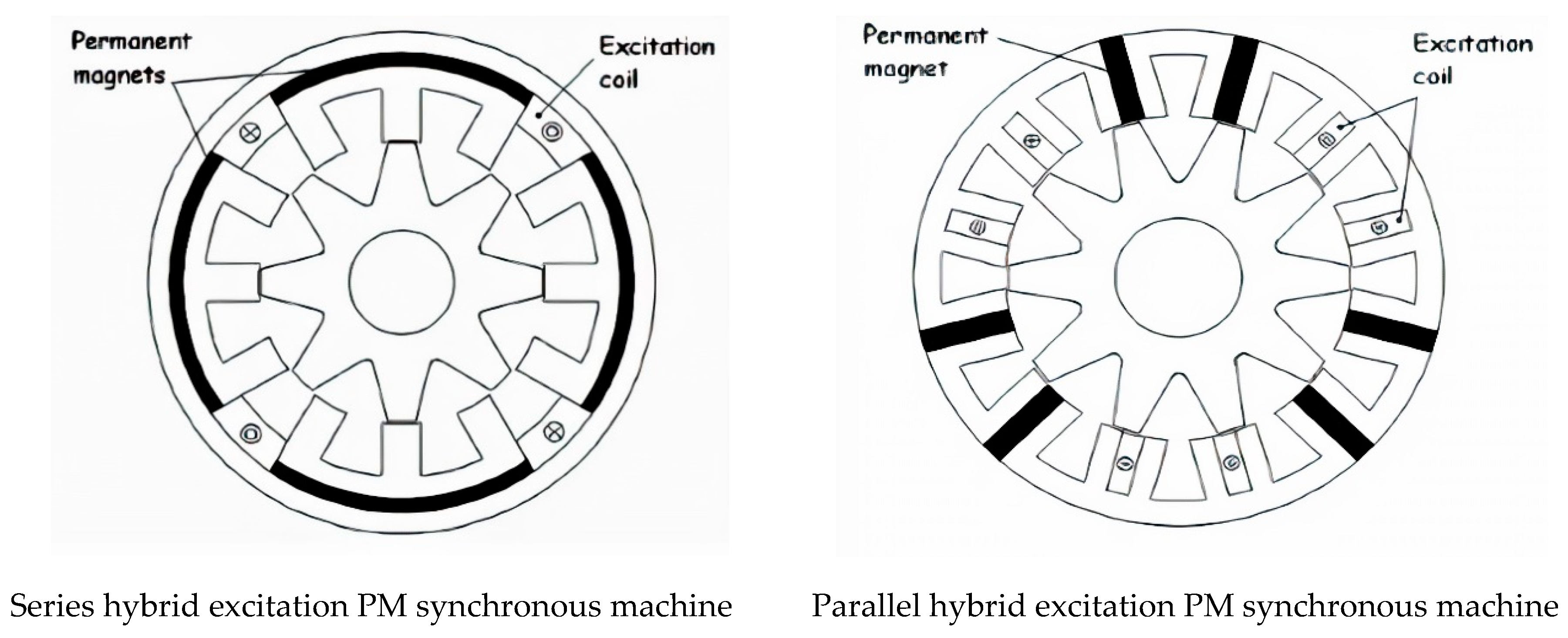
Figure 1. Main types of hybrid excited salient permanent-magnet synchronous motor (HEPMSM).
Wevj 11 00042 g001
Figure 2. HEPMSM equivalent circuit including core loss resistance.
Wevj 11 00042 g002
Figure 3. (a) Ideal output characteristics of traction motor drive; (b) Tractive effort and power versus vehicle speed with different speed ratios [19].
Wevj 11 00042 g003
Figure 4. HEPMSM phasor diagram with zero direct-axis (ZDAC).
Wevj 11 00042 g004
Figure 5. (a) Flux-weakening control using +ve and –ve field current (FC); (b) proposed flux-weakening control using +ve FC.
Wevj 11 00042 g005
Figure 6. DC field current effect on constant power speed range (CPSR).
Wevj 11 00042 g006
Figure 7. Stator current versus torque at reduced positive and reversed field current (FC).
Wevj 11 00042 g007
Figure 8. Output, input power, and torque at reduced and reversed FC.
Wevj 11 00042 g008
Figure 9. Stator voltage and EMF at reduced and reversed FC.
Wevj 11 00042 g009
Figure 10. Stator current and its components at reduced and reversed FC.
Wevj 11 00042 g010
Figure 11. Stator voltage components at reduced positive and reversed FC.
Wevj 11 00042 g011
Figure 12. Efficiency and power factor excitation at reduced and reversed FC.
Wevj 11 00042 g012
Figure 13. PM, DC field and maximum flux at reduced and reversed FC.
Wevj 11 00042 g013
Figure 14. Electric vehicle (EV) motor torque/speed patterns.
Wevj 11 00042 g014
Figure 15. EV motor power/speed patterns. R: Rated torque operation with low acceleration, light load, and less stable speed operating region with less speed ratio; B: Optimum torque with about 40% higher than required power, (overdesign), low acceleration, and less stable speed operating region with less speed ratio; O: Optimum maximum torque with high acceleration and MTPA with a high-speed ratio.
Wevj 11 00042 g015
Figure 16. EV motor current/speed patterns.
Wevj 11 00042 g016
Figure 17. Torque and the stator q current component as affected by stator mutual flux.
Wevj 11 00042 g017
Figure 18. HEPMSM simulation model.
Wevj 11 00042 g018
Figure 19. Simulation results at the base and rated speed operating patterns. (a,b) Dynamic results as compared by steady-state characteristics. (cg) Dynamic characteristics at CT up to base speed (proposed) as compared by CT up to rated speed (conventional).
Wevj 11 00042 g019aWevj 11 00042 g019b