Article

Fault Injection Model of Induction Motor for Stator Interturn Fault Diagnosis Research Based on HILS

Technology Centre, CRRC Qingdao Sifang Rolling Stock Research Institute Co., Ltd., Qingdao 266000, China
*
Author to whom correspondence should be addressed.
World Electr. Veh. J. 2021, 12(4), 170; https://doi.org/10.3390/wevj12040170
Submission received: 13 August 2021 / Revised: 24 September 2021 / Accepted: 26 September 2021 / Published: 29 September 2021

Abstract

:
Recently, in order to ensure the reliability and safety of trains, online condition monitoring and fault diagnosis of traction induction motors have become active issues in the area of rail transportation. The fault diagnosis algorithm can be developed and debugged in a real-time environment based on hardware-in-the-loop simulation (HILS). However, the dynamic space model of induction motors with stator interturn short-circuit faults faces the problem that the faulty state and the healthy state are not compatible, which is inconvenient for the HILS. In this paper, a fault injection model is proposed for the first time, which can realize the online switching between the healthy state and the faulty state of the motor. The feasibility and effectiveness of the proposed model are verified by simulation experiments the based on MATLAB/Simulink and dSPACE HILS platforms.

1. Introduction

Regarded as the “heart” of rolling stock, traction systems provide the tractive effort to support the continuous operations of trains, and their safety and reliability are therefore crucial [1]. Traction system failures may cause catastrophic accidents to rail vehicles. Therefore, regular maintenance is needed in order to ensure the safety of rail vehicles—that is, “plan-based repair”. This can face problems such as over-maintenance, missed inspections, and untimely maintenance. Recently, prognostics and health management (PHM) of traction systems have brought new solutions, which can transform the traditional “plan-based repair” into “condition-based repair”, improving vehicle maintenance efficiency and vehicle operating reliability [2,3].
The asynchronous traction motor is the core component of the traction system, responsible for the output of kinetic energy necessary to complete the transformation of electric energy to mechanical energy. Therefore, online condition monitoring and fault diagnosis of traction induction motors are an indispensable part of traction PHM systems [4].
The stator insulation fault is one of the typical induction motor faults. Most stator insulation failures stem from interturn short-circuits caused by interturn insulation breakdown. Then, the high voltage potential differences between adjacent coils cause a large circulating current to flow in the shorted turns, further damaging the insulation as a result of the abnormal heat generated, causing the rapid spread of insulation failure, and gradually developing into a more serious phase-to-phase or phase-to-ground fault [5,6,7,8]. Therefore, incipient detection of interturn faults is essential in order to avoid hazardous operating conditions.
Modelling of faulty induction motors is the first step to study fault diagnosis algorithms. The model of induction motors with interturn short-circuit faults has been studied in some of the literature [9,10,11,12,13], and the state-space representation of the dynamic equations suitable for digital simulation has been presented. However, although there are some differences in the details, such as the calculation method of leakage inductance [12] and the consideration of magnetic saturation [13], all of these models model the faulty motor as a whole, meaning that the healthy part and the faulty part of the motor are integrated rather than modeled separately. Due to the presence of fault parameters, these models can only be used for fault simulation, and cannot be switched to a healthy state. Therefore, the dynamic space model of induction motors with stator interturn short-circuit faults faces a problem in that the faulty state and the healthy state are not compatible.
The hardware-in-the-loop simulation (HILS) platform based on dSPACE perfectly combines the software system with the hardware system, including the processor and I/O interface, which can realize the software development and testing in a real-time environment [14,15]. Compared with offline simulation, HILS can not only verify the effectiveness of the fault diagnosis algorithm, but also evaluate the online real-time response ability, assist in parameter tuning, and improve the efficiency of algorithm development. However, dSPACE’s online simulation mode can only activate one model at a time. In other words, model parameters can be adjusted online, but model transformation can only be done offline. If the healthy motor and the fault motor are modelled separately, the switch from the healthy state to the fault state cannot be realized directly in the online simulation; thus, the real-time response ability of the fault diagnosis algorithm cannot be evaluated effectively.
In this context, a fault injection model is proposed in this paper, which can directly inject the interturn fault into the healthy motor during the online simulation in order to realize the switch from the healthy state to the faulty state. First, the internal relationship between the interturn short-circuit fault and the healthy motor is analyzed, where the defective winding can be equivalent to a coil flowing through the reverse short-circuit current and a normal winding. Then, the short-circuit coil is modeled and used as the source of fault injection, which can produce a short-circuit current that affects the phase current of the healthy motor. In contrast to the dynamic space models of motors with interturn faults, only the fault injection model contains fault parameters. Thus, it can simply set the fault parameter to zero in order to switch to the healthy state. The feasibility and effectiveness of the proposed model are verified by simulation experiments based on the MATLAB/Simulink and dSPACE HILS platforms.

2. Classical Model of Induction Motor with Interturn Fault

2.1. Dynamic Mathematical Model

The stator winding equivalent structure of an induction motor with an interturn short-circuit fault is shown in Figure 1a. The interturn fault divides A-phase winding into as1 and as2 parts, where as1 represents the normal winding coil and as2 represents the part that is short-connected in the winding. Considering the short-circuit fault in the initial stage, Rf represents the short-circuit resistance in the short-circuit, and if is defined as the short-circuit current of the short-circuit branch.
Based on the above structure, the voltage equations of the faulty motor in the three-phase static coordinate system can be expressed as follows:
{ u s = R s i s + d ψ s d t + μ A 1 i f 0 = R r i r + d ψ r d t
and the flux linkage expressions are:
{ ψ s = L s s i s + L s r i r + μ A 2 i f ψ r = L s r T i s + L r r i r + μ A 3 i f
where μ = Nas2/Nas is the ratio of the number of short-circuit turns to the total number of the located phase, and is defined as the fault factor; us is the stator voltage matrix; is is the stator current matrix; ir is the rotor current matrix; ψs is the stator flux matrix; ψr is the rotor flux matrix; Rs is the stator resistance; Rr is the rotor resistance; Lss is the stator self-inductive matrix; Lrr is the rotor self-inductive matrix, Lsr is the stator and rotor mutual inductance matrix; and A1, A2, and A3 are the fault coefficient matrixes. The specific definitions are as follows:
u s = [ u a s u b s u c s ] T ;   i s = [ i a s i b s i c s ] T ;   i r = [ i a r i b r i c r ] T ;   ψ s = [ ψ a s ψ b s ψ c s ] T ;   ψ r = [ ψ a r ψ b r ψ c r ] T ; L s s = [ L m s + L l s 1 2 L m s 1 2 L m s 1 2 L m s L m s + L l s 1 2 L m s 1 2 L m s 1 2 L m s L m s + L l s ] ; L r r = [ L m s + L l r 1 2 L m s 1 2 L m s 1 2 L m s L m s + L l r 1 2 L m s 1 2 L m s 1 2 L m s L m s + L l r ] ; L s r = L m s [ cos θ cos ( θ + 2 π 3 ) cos ( θ 2 π 3 ) cos ( θ 2 π 3 ) cos θ cos ( θ + 2 π 3 ) cos ( θ + 2 π 3 ) cos ( θ 2 π 3 ) cos θ ] ; A 1 = [ R s 0 0 ] T ;   A 2 = [ L m s + L l s 1 2 L m s 1 2 L m s ] T ; A 3 = L m s [ cos θ cos ( θ + 2 π 3 ) cos ( θ 2 π 3 ) ] T
where Lms is the stator excitation inductance, Lls is the stator leakage inductance, Llr is the rotor leakage inductance, and θ is the relative position angle of stator and rotor.
The description equation of the short-circuit coil can be expressed as follows:
{ u a s 2 = μ R s ( i a s i f ) + d ψ a s 2 d t = R f i f ψ a s 2 = μ A 2 T i s μ A 3 T i r μ ( L l s + μ L m ) i f
where uas2 is the short-circuit voltage and ψas2 is the flux in the short-circuit part.
The electromagnetic torque equation is:
T e = p L m s i s T L s r θ i r μ p L m s i f ( 3 2 i a r sin θ + 3 2 ( i b r i c r ) cos θ )
where p is the number of pole pairs.
The first term in Equation (4) is the standard expression for torque developed by a symmetrical induction machine. The second term, which is the effect of the turn fault, results in a double-line-frequency pulsation in the torque and speed.

2.2. Dynamic Space Model

After transforming Equations (1)–(4) to the two-phase coordinate system, referring to [9] for details, the state-space model used for digital simulation can be sorted out and obtained, as follows:
x ˙ = A x + B u y = C x
x = [ ψ α s ψ β s ψ α r ψ β r ψ a s 2 ] T ;   y = [ i α s i β s i α r i β r i f ] T ; M = [ L s 0 L m 0 2 3 μ L s 0 L s 0 L m 0 L m 0 L r 0 2 3 μ L m 0 L m 0 L r 0 μ L s 0 μ L m 0 ( 2 3 μ 2 L m + μ L l s ) ] ; A = [ R s C 1 + 2 3 μ R s C 5 R s C 2 R r C 3 + [ 0 0 0 0 ω r 0 ] R r C 4 + [ 0 0 0 ω r 0 0 ] μ R s C 1 + ( R f + μ R s ) C 5 ] ; B = [ 1 0 0 0 0 0 1 0 0 0 ] T ;   u = [ u α s u β s ] ;
C = M−1; Ci is the ith row of C.
The electromagnetic torque in space-vector notation is:
T e = 3 2 p L m ( i α r i β s i α s i β r ) μ p L m i f i β r
The mechanical equation following Newton’s second Law is:
{ d ω r d t = p T e T L J d θ r d t = ω r

2.3. Drawbacks of Classical Model

When there is no fault—that is, μ = 0—the matrix M in Equation (5) is not full rank and cannot be inverse, which makes the ordinary differential equation (ODE) solver ineffective. Therefore, the classical interturn fault motor model cannot achieve compatibility between the faulty state and the healthy state, so the faulty motor and the healthy motor can only be modelled separately. However, dSPACE’s online simulation mode can only activate one model at a time. In other words, model parameters can be adjusted online, but model transformation can only be done offline. In this way, it is impossible to directly switch the health state to the faulty state in the online simulation, and the real-time response ability of the fault diagnosis algorithm cannot be effectively evaluated.
On the other hand, the workload of the hardware-in-loop simulation modelling of the motor is huge. If only a fault injection model is added on the basis of the original healthy motor model, the workload of the simulation construction will be greatly reduced.
Moreover, based on fault injection, the fault degree can be flexibly changed online, and the trend of fault characteristics with the degree of fault can be observed more effectively.

3. Proposed Fault Injection Model

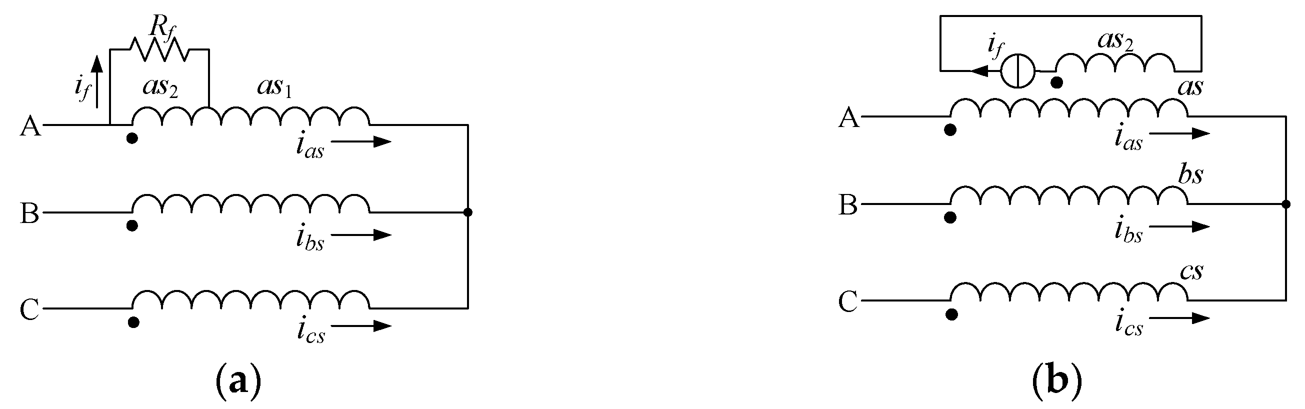
3.1. Essence of Stator Interturn Fault

When the short-circuit of A-phase winding occurs, there is essentially an additional short-circuit coil loop flowing through the reverse short-circuit current. The short-circuit current affects the A-phase current which, in turn, affects the flux and torque. According to the superposition principle, the fault motor is equivalent to two parts: the normal symmetrical winding, and the short-circuit coil flowing through the reverse short-circuit current. The stator winding equivalent structure of the fault motor after fault separation is shown in Figure 1b. Clearly, the classic fault motor model can be equivalent to a healthy motor model plus a fault injection model obtained by modelling the short-circuit coil.
When the A-phase winding has an inter-turn short-circuit, compared with the normal motor, only the A-phase current changes in the expression, and the change can be expressed in the two-phase coordinate system as Equation (8). The theoretical derivation of Equation (8) is shown in Appendix A.
i α s = i α s heathy + 2 3 μ i f
where i α s heathy is the α-axis component of the stator current of the healthy motor, and iαs is the α-axis component of the stator current after fault injection.
The rotor current and β-axis component of the motor’s stator current are not affected by fault injection in terms of the expressions shown in Appendix A.

3.2. Stator Interturn Fault Injection Model

According to the analysis in Section 3.1, the short-circuit coil flowing through the reverse short-circuit current can be modeled as the source of fault injection, which can produce a short-circuit current that affects the phase current of the healthy motor.
Transform Equation (3) to a two-phase coordinate system to obtain
{ R f i f = μ R s ( i α s i f ) + d ψ a s 2 d t ψ a s 2 = μ L s i α s + μ L m i α r ( 2 3 μ 2 L m + μ L l s ) i f
Then, substitute Equation (8) into Equation (9) to obtain
{ d ψ a s 2 d t = ( R f + μ R s 2 3 μ 2 R s ) i f μ R s i α s heathy ψ a s 2 = ( 2 3 μ 2 L s 2 3 μ 2 L m μ L l s ) i f + μ L s i α s heathy + μ L m i α r
Equation (10) can be used as an independent fault injection source to output the short-circuit current if, and then the α-axis component of the motor stator current after fault injection can be obtained from Equation (8).

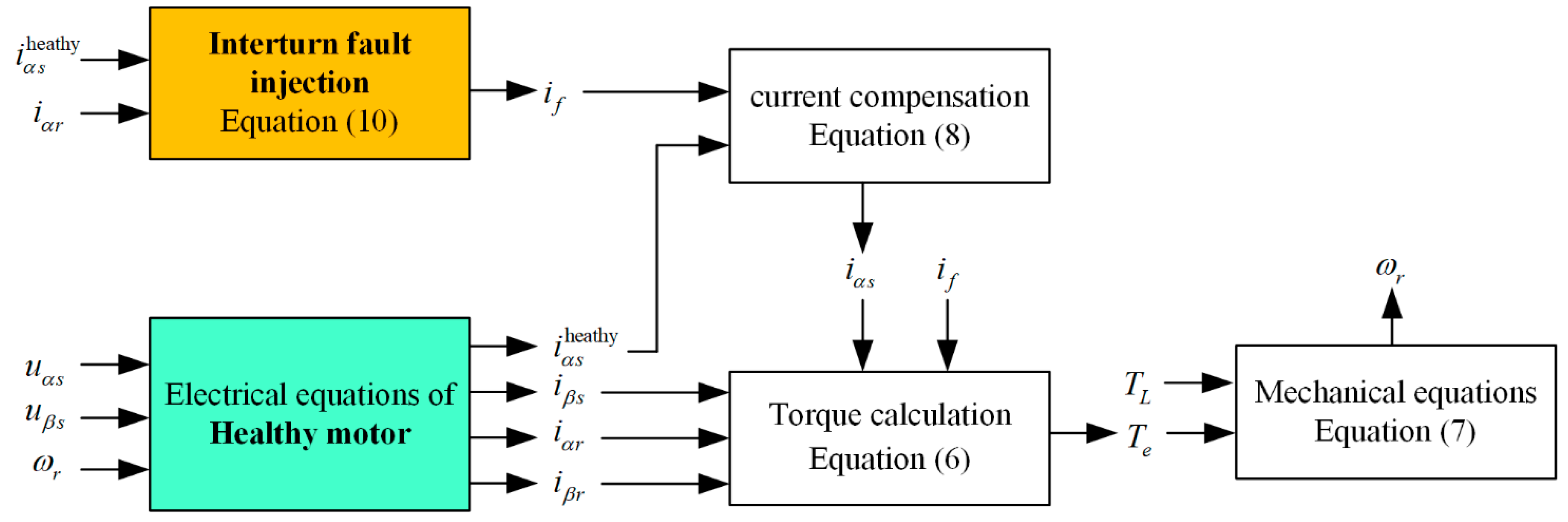
3.3. Overall Model of Induction Motor with Stator Interturn Fault Injection

The input-output relationship between the overall fault injection model and the healthy motor model is shown in Figure 2. The electrical part of the healthy motor outputs the healthy currents, and then the interturn fault injection outputs the short-circuit current. After current compensation using Equation (8), the α-axis component of the stator current after fault injection can be obtained. Then, the electromagnetic torque and speed can be obtained using the torque equation and the mechanical equations, which are consistent with Equations (6) and (7), respectively. The electrical equations of the healthy motor model will not be described in detail in this paper.
In contrast to the dynamic space models of motors with interturn faults shown in Equation (5), only the fault injection model (Equation (10)) contains fault parameters. When the fault parameter μ is set to zero, the fault injection model does not work. At the time, only the healthy motor model is running, and the desired interturn fault can be injected by changing the fault parameters μ and Rf.

4. Simulation Results

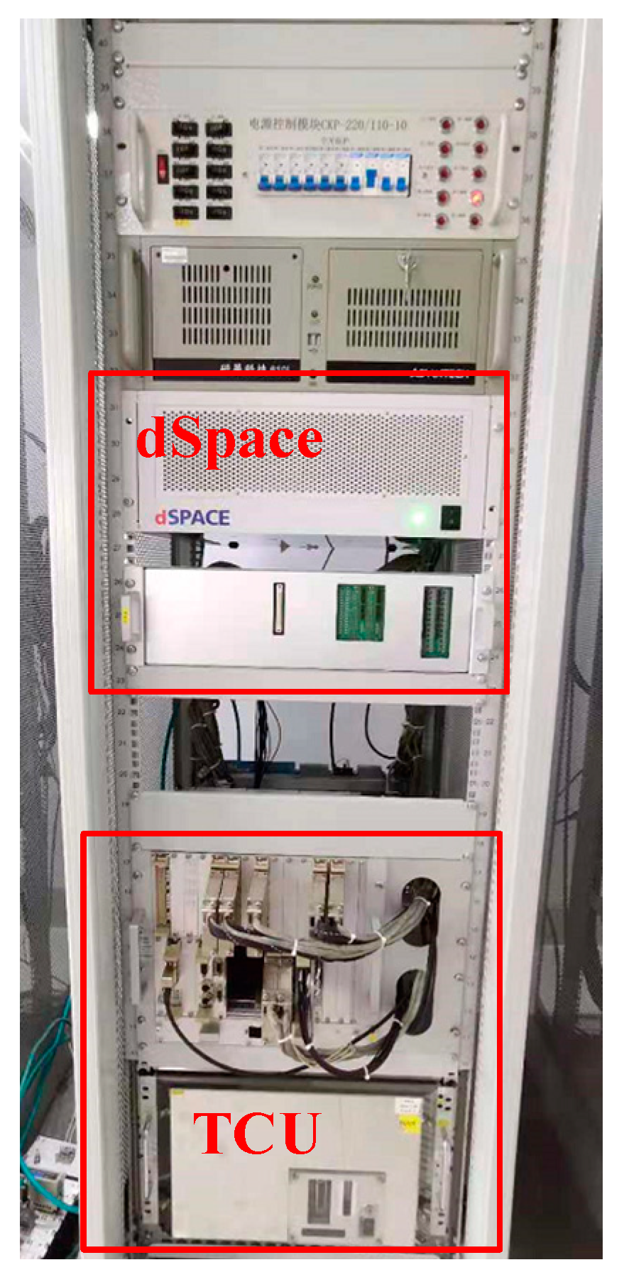
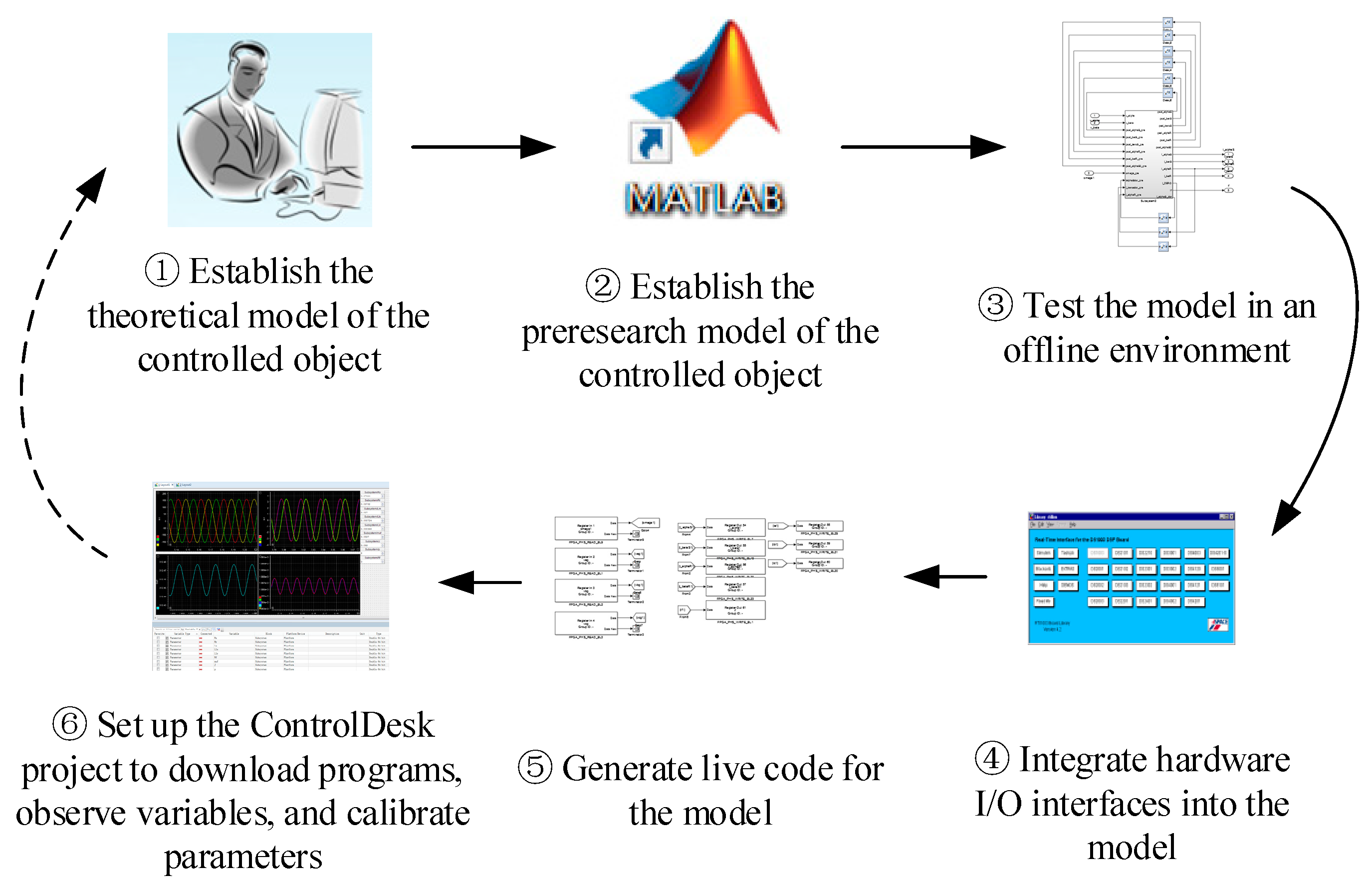
4.1. Hardware-in-the-Loop Simulation

The simulated controlled object model can run in real time in the hardware-in-the-loop simulation, and is controlled by a real controller. The hardware-in-the-loop simulation platform based on dSPACE perfectly combines the software system with the hardware system, including the processor and I/O interface, which can realize the software development and testing in the real-time environment. Compared with offline simulation, hardware-in-the-loop real-time simulation can not only verify the effectiveness of the fault diagnosis algorithm, but also evaluate the online real-time response ability of the algorithm, assist in parameter tuning, and improve the efficiency of algorithm development.
Figure 3 shows the physical diagram of the hardware-in-the-loop simulation platform for the development, testing, and research of the traction systems of rail vehicles. The dSPACE hardware system contains the processor, component board cards, and I/O resources. The traction control unit (TCU) is the actual controller.
The development process of HILS is shown in Figure 4.

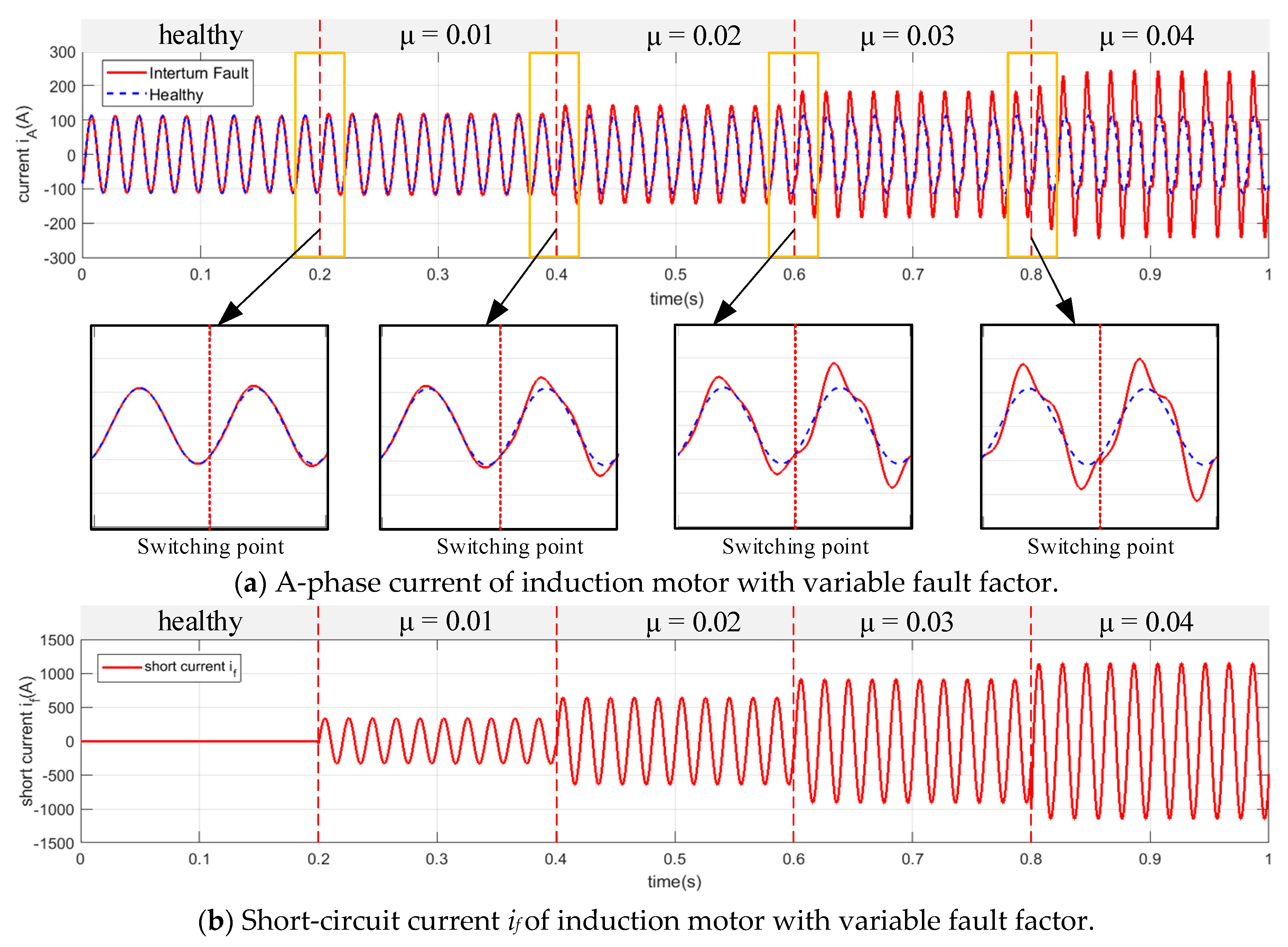
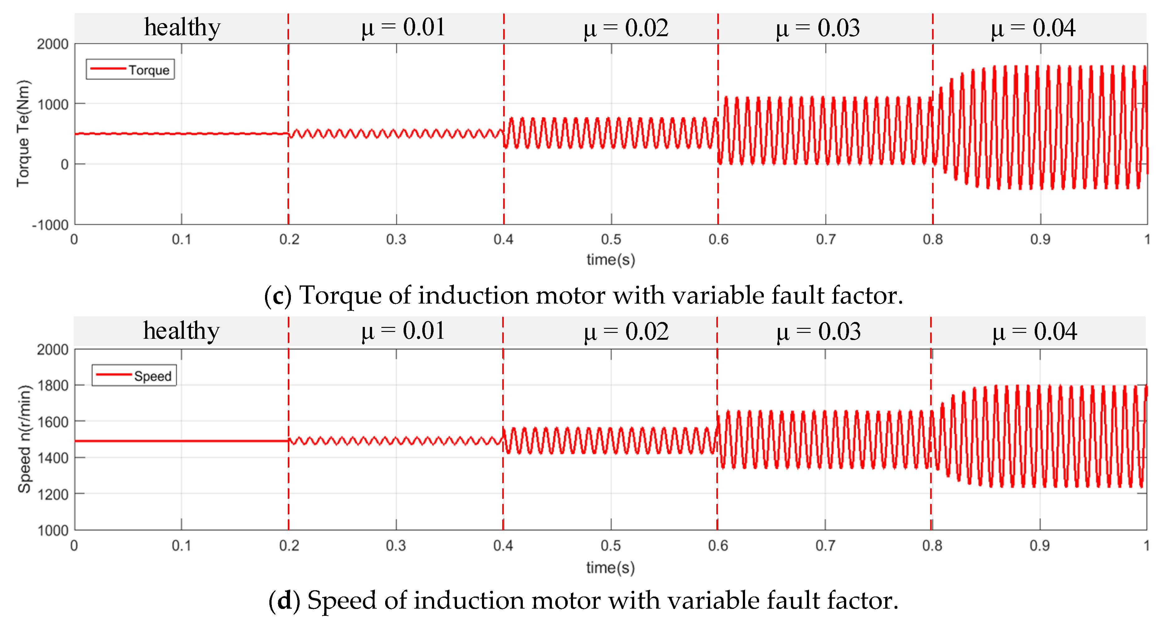
4.2. Simulation Results

In this paper, a 210 kW traction induction motor is taken as an example to carry out the hardware-in-the-loop simulation of interturn short-circuit fault injection. Motor parameters are shown in Table 1.
It should be noted that the main contribution of this paper is to propose an inter-turn short-circuit fault injection model that can achieve the switch from healthy motor to fault motor in the HILS. This paper only carried out simulation research, aiming at the induction motor fed by an open-loop three-phase symmetric power supply, but it is sufficient to demonstrate the validity of the model. The influence of inverter-fed drives and closed-loop control on fault behaviors will be further studied in the future.
The simulation results of fault-state switching are shown in Figure 5. Figure 5a shows the comparison of A-phase current waveforms from the fault injection model and the normal motor model. During 0–0.2 s, the fault factor μ = 0, and the fault injection model does not work, so the simulation results are consistent with the normal healthy motor model. Then, the fault factor μ is switched to 0.01, 0.02, 0.03, and 0.04 at 0.2 s, 0.4 s, 0.6 s, and 0.8 s, respectively. It is clear that the distortion of the current waveform becomes more and more serious with the increase in the fault factor. It can also be seen from Figure 5b–d that the short-circuit current and the fluctuations in torque and speed become larger with the increase in the fault factor. The above simulation results show that the fault injection model proposed in this paper can effectively realize the fault state switching of the induction motor in online HIL simulation.
Figure 6 shows the time-frequency spectrum of the A-phase current waveforms shown in Figure 5a. The odd harmonics increase gradually with the increase in the fault factor. This is merely a data analysis case to illustrate that online state changing can more effectively observe the variation trend of fault characteristics with fault degree. The fault injection can even generate functions with fault parameters μ and Rf as independent variables to realize the desired faulty state evolution process.

5. Conclusions

In this paper, an interturn short-circuit fault injection model is proposed for the first time, which can directly inject the interturn fault into the healthy motor. Unlike the dynamic space model of motors with interturn faults, only the fault injection model contains fault parameters; thus, it can switch to the healthy state by simply setting the fault parameters to zero. Based on this model, the online switching between the healthy motor and the faulty motor can be realized in the HILS. The main contributions are as follows:
  • The essence of inter-turn short-circuit faults of induction motors is revealed;
  • The concept of modeling the fault source and the healthy motor separately is proposed, which can reduce the workload of modeling and improve the application functions.
The simulation results show that the fault injection model proposed in this paper can effectively realize the fault state switching (including from healthy to faulty) of induction motors, and can observe the variation trend of fault characteristics with fault degree.

Author Contributions

Conceptualization, validation, investigation, data curation, writing—original draft preparation, visualization, X.Z.; methodology, formal analysis, X.Z. and K.H. (Kun Han); resources, writing—review and editing, K.H. (Kun Han), H.C. and X.Z.; software, X.Z. and Z.W.; investigation, X.Z. and K.H. (Ke Huo); supervision, K.H. (Kun Han); project administration, H.C. All authors have read and agreed to the published version of the manuscript.

Funding

This research received no external funding.

Conflicts of Interest

All authors are employees of CRRC Qingdao Sifang Rolling Stock Research Institute Co., LTD. The paper reflects the views of the scientists, and not the company.

Appendix A

Transform Equations (1) and (2) to the two-phase coordinate system, in combination with Equation (8), and the internal relationship between healthy motor and faulty motor can be obtained as follows:
[ u α s u β s 0 0 ] = [ R s R s R r R r ] [ i α s i β s i α r i β r ] + d d t [ ψ α s ψ β s ψ α r ψ β r ] + [ ω r ω r ] [ ψ α s ψ β s ψ α r ψ β r ] [ 2 3 μ R s 0 0 0 ] i f
i α s = i α s healthy + 2 3 μ i f [ u α s u β s 0 0 ] = [ R s R s R r R r ] [ i α s Healthy i β s i α r i β r ] + d d t [ ψ α s ψ β s ψ α r ψ β r ] + [ ω r ω r ] [ ψ α s ψ β s ψ α r ψ β r ]
[ ψ α s ψ β s ψ α r ψ β r ] = [ L s L m L s L m L m L r L m L r ] [ i α s i β s i α r i β r ] [ 2 3 μ L s 0 2 3 μ L m 0 ] i f i α s = i α s healthy + 2 3 μ i f [ ψ α s ψ β s ψ α r ψ β r ] = [ L s L m L s L m L m L r L m L r ] [ i α s healthy i β s i α r i β r ]
To the left and right of the symbol “ ” are the equations of the faulty motor and the healthy motor, respectively. Clearly, Equation (8) can reveal the internal relationship between the motor with an interturn short-circuit fault and the healthy motor.

References

  1. Jiang, B.; Wu, Y.K.; Ning-Yun, L.; Ze-Hui, M. Review of fault diagnosis and prognosis techniques for high-speed railway traction system. Control Decis. 2018, 33, 841–854. [Google Scholar] [CrossRef]
  2. Chen, Z.; Zhang, S.; Xu, H. Research on the Overall Scheme of Electric Locomotive Fault Prognostics and Health Management System. Electr. Drive Locomot. 2021, 3, 125–132. [Google Scholar] [CrossRef]
  3. Liu, K.; Dai, J.; Xu, H. Condition Repair Technology and System Solutions for Key Components of Urban Rail Vehicles. Electr. Drive Locomot. 2020, 4, 1–7. [Google Scholar] [CrossRef]
  4. Chen, H.; Jiang, B.; Ding, S.X.; Huang, B. Data-Driven Fault Diagnosis for Traction Systems in High-Speed Trains: A Survey, Challenges, and Perspectives. IEEE Trans. Intell. Transp. Syst. 2020, 1–17. [Google Scholar] [CrossRef]
  5. Trigeassou, J.C. Electrical Machines Diagnosis, 1st ed.; John Wiley & Sons: Hoboken, NJ, USA, 2012. [Google Scholar]
  6. Siddique, A.; Yadava, G.S.; Singh, B. A review of stator fault monitoring techniques of induction motors. IEEE Trans. Energy Convers. 2005, 20, 106–114. [Google Scholar] [CrossRef]
  7. Zhang, P.; Du, Y.; Habetler, T.G.; Lu, B. A Survey of Condition Monitoring and Protection Methods for Medium-Voltage Induction Motors. IEEE Trans. Ind. Appl. 2011, 47, 34–46. [Google Scholar] [CrossRef]
  8. Xu, Z.; Hu, C.; Yang, F.; Kuo, S.H.; Goh, C.K.; Gupta, A.; Nadarajan, S. Data-driven Inter-Turn Short Circuit Fault Detection in Induction Machines. IEEE Access 2017, 5, 25055–25068. [Google Scholar] [CrossRef]
  9. Rangarajan, M.; Habetler, T.G.; Harley, R.G. Transient Model for Induction Machines with Stator Winding Turn Faults. IEEE Trans. Ind. Appl. 2002, 38, 632–638. [Google Scholar] [CrossRef]
  10. Patel, D.C.; Chandorkar, M.C. Modeling and Analysis of Stator Interturn Fault Location Effects on Induction Machines. IEEE Trans. Ind. Electron. 2014, 61, 4552–4564. [Google Scholar] [CrossRef]
  11. Berzoy, A.; Mohamed, A.; Mohammed, O.A. Dynamic Space-Vector Model of Induction Machines with Stator Inter-Turn Short-Circuit Fault. In Proceedings of the ECON 2015—41st Annual Conference of the IEEE Industrial Electronics Society, Yokohama, Japan, 9–12 November 2015. [Google Scholar]
  12. Berzoy, A.; Ahmed ASMohamed, O.A. Complex-Vector Model of Interturn Failure in Induction Machines for Fault Detection and Identification. IEEE Trans. Ind. Appl. 2017, 53, 2667–2679. [Google Scholar] [CrossRef]
  13. Nandi, S. A detailed model of induction machines with saturation extendable for fault analysis. IEEE Trans. Ind. Appl. 2004, 40, 1302–1309. [Google Scholar] [CrossRef]
  14. Qu, K.; Wu, Q.; Chen, Y.; Zhang, H. Design of Hardware-in-the-Loop Simulation Platform for Traction and Load Simulation of Urban Rail Transit Vehicles. Micromotors 2020, 53, 91–95. [Google Scholar] [CrossRef]
  15. Yang, X.; Yang, C.; Peng, T.; Chen, Z.; Liu, B.; Gui, W. Hardware-in-the-Loop Fault Injection for Traction Control System. IEEE J. Emerg. Sel. Top. Power Electron. 2018, 6, 696–706. [Google Scholar] [CrossRef]
Figure 1. (a) The equivalent winding structure and (b) equivalent fault separation structure of Y-connected stator windings with interturn short-circuit faults.
Wevj 12 00170 g001
Figure 2. Block diagram of induction motor with interturn fault injection.
Wevj 12 00170 g002
Figure 3. HILS platform.
Wevj 12 00170 g003
Figure 4. Development process of HILS.
Wevj 12 00170 g004
Figure 5. Simulation results of faulty state switching based on fault injection.
Wevj 12 00170 g005aWevj 12 00170 g005b
Figure 6. Time-frequency spectrum of A-phase current with fault injection.
Wevj 12 00170 g006
Table 1. Motor parameters.
ParameterValueParameterValue
Stator resistance76.24 mΩRated power210 kW
Rotor resistance57.82 mΩExcitation inductance18 mH
Stator leakage inductance0.724 mHPole pairs2
Rotor leakage inductance0.868 mH
Publisher’s Note: MDPI stays neutral with regard to jurisdictional claims in published maps and institutional affiliations.

