


Design and Analysis of a Novel Adjustable SVAWT for Wind Energy Harvesting in New Energy Vehicle
Abstract
:1. Introduction
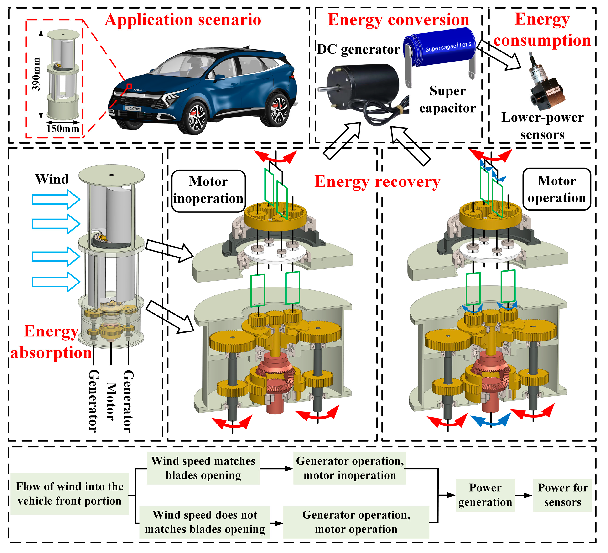
2. System Design
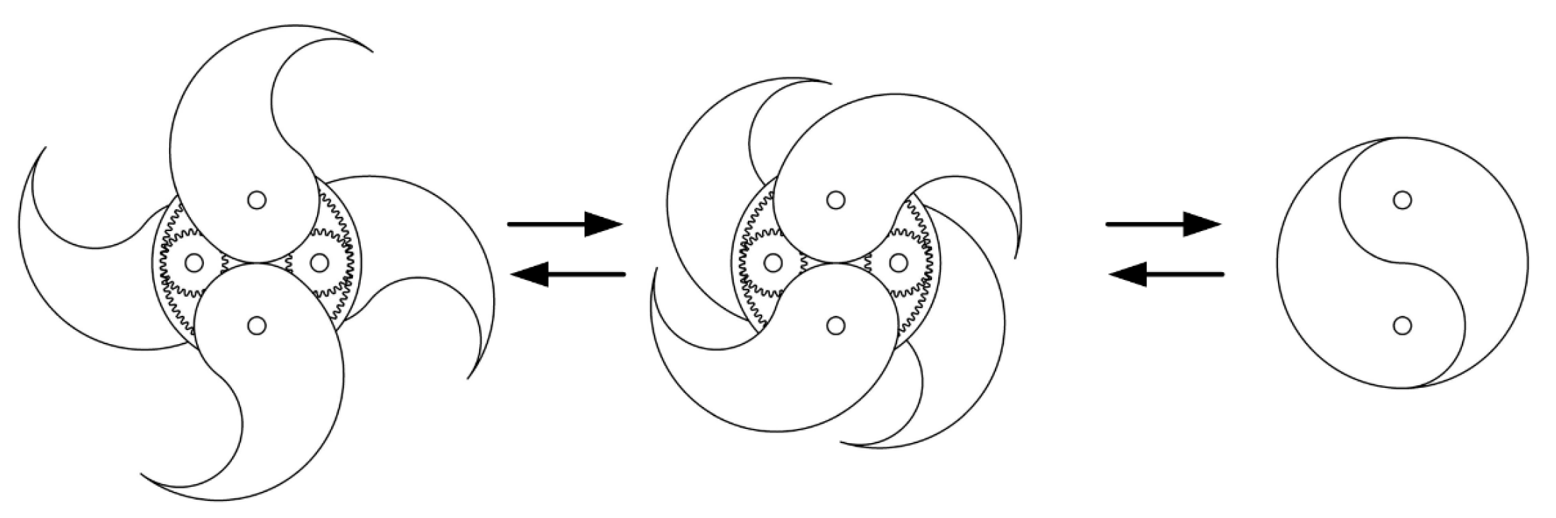
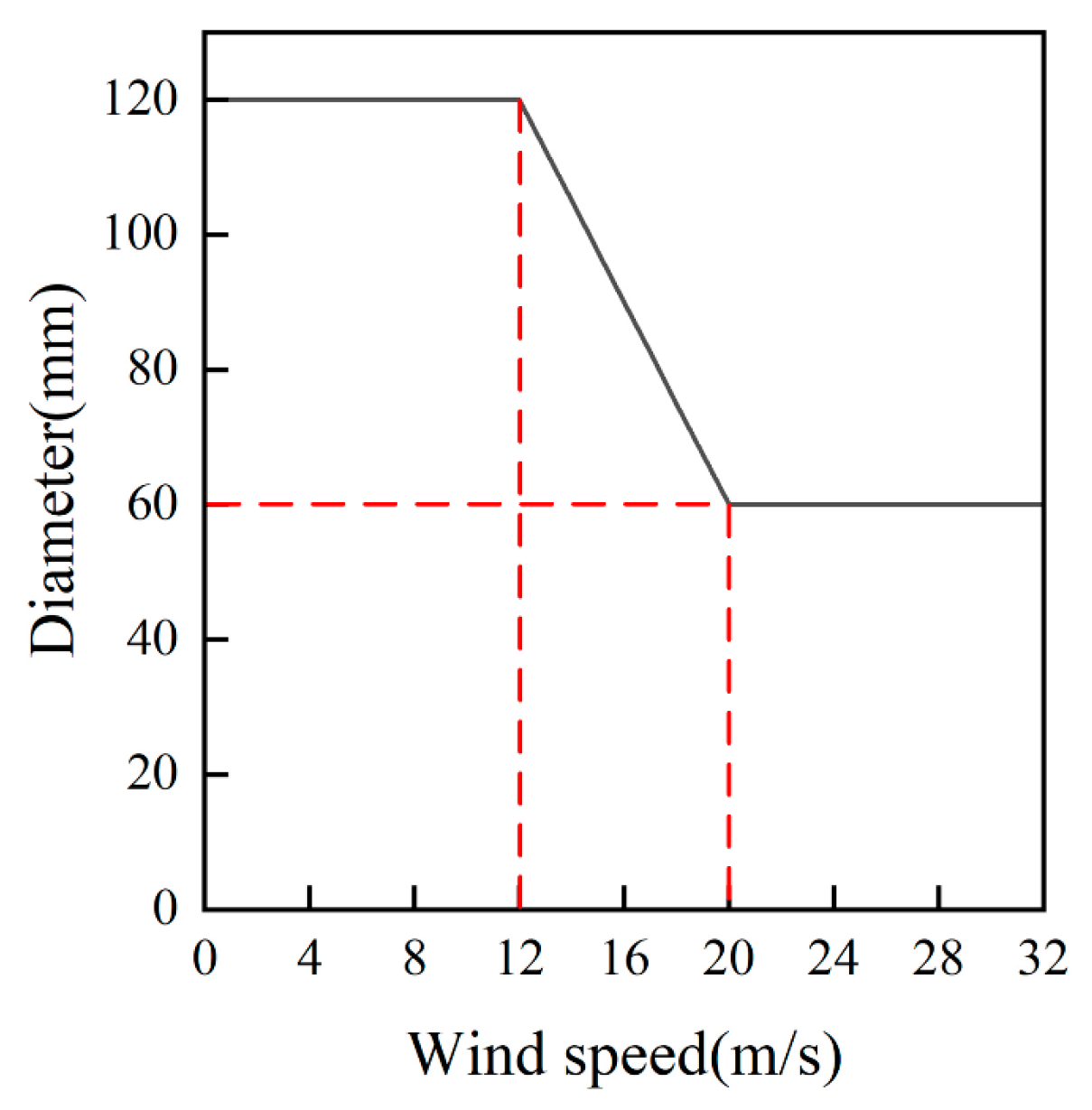
2.1. Energy Absorption Module
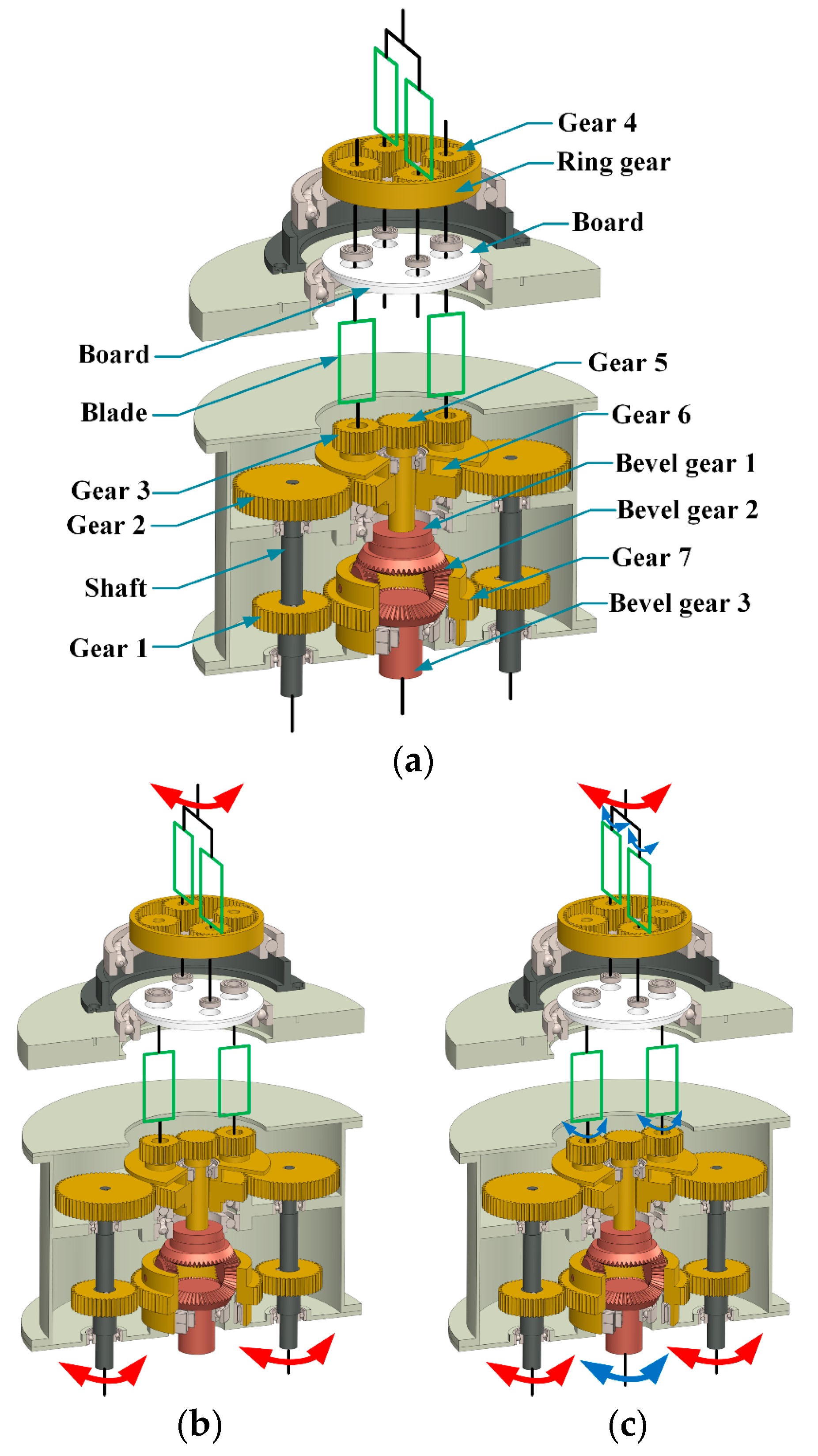
2.2. Energy Recovery Module
2.2.1. Inoperative Motor
2.2.2. Motor Operation
2.3. Energy Conversion Module
3. Modeling and Analysis
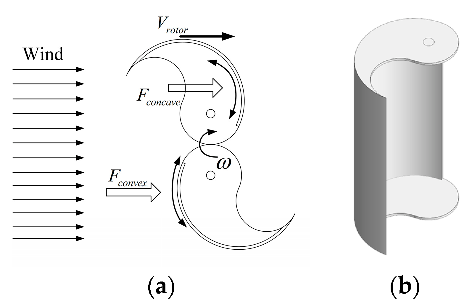
3.1. Rotor Model
3.1.1. Rotational Energy of Components
3.1.2. Energy of Overlapping Damping Force of the Novel Adjustable SVAWT
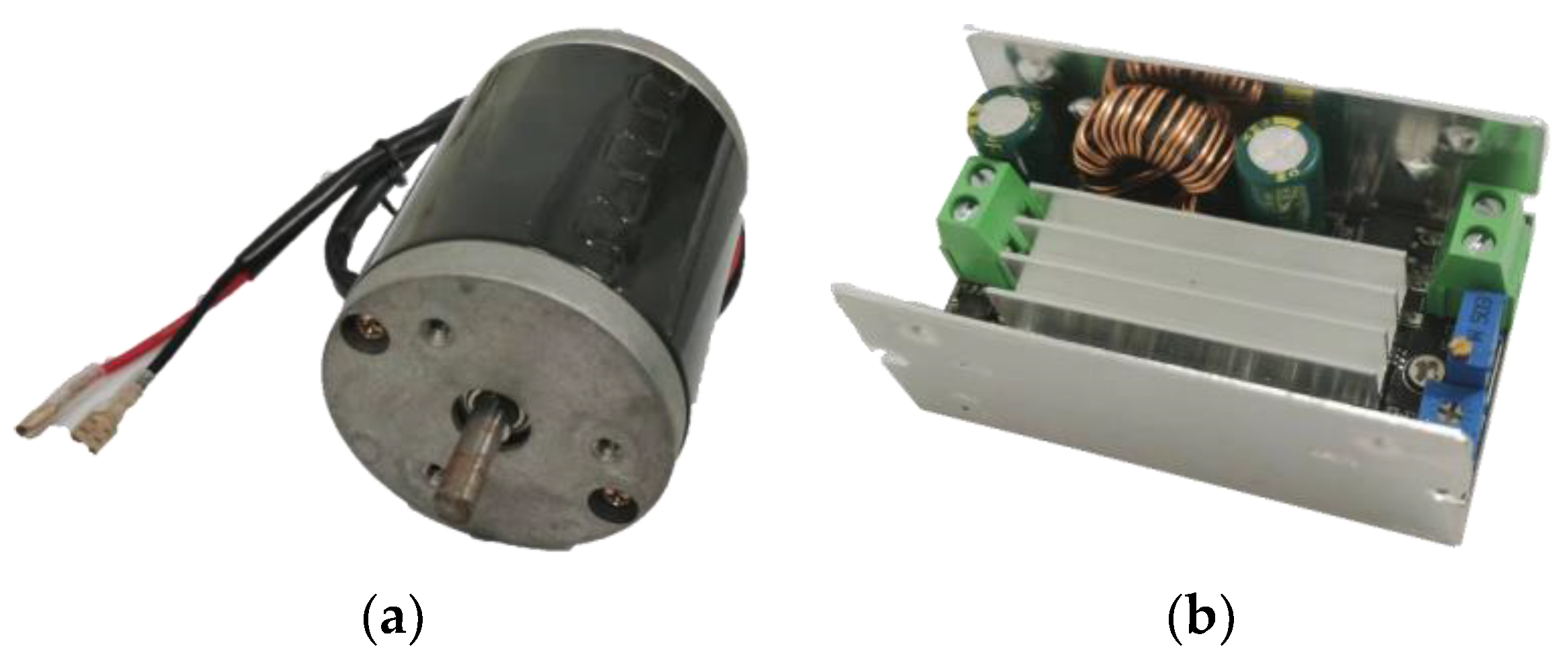
3.2. Generator Model
3.3. Efficiency Analysis of the Novel Adjustable SVAWT
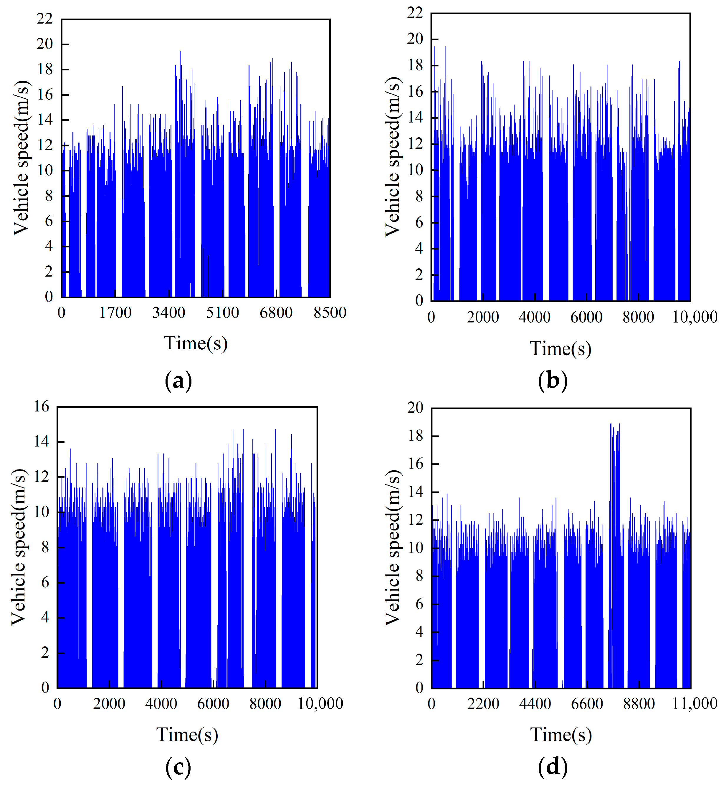
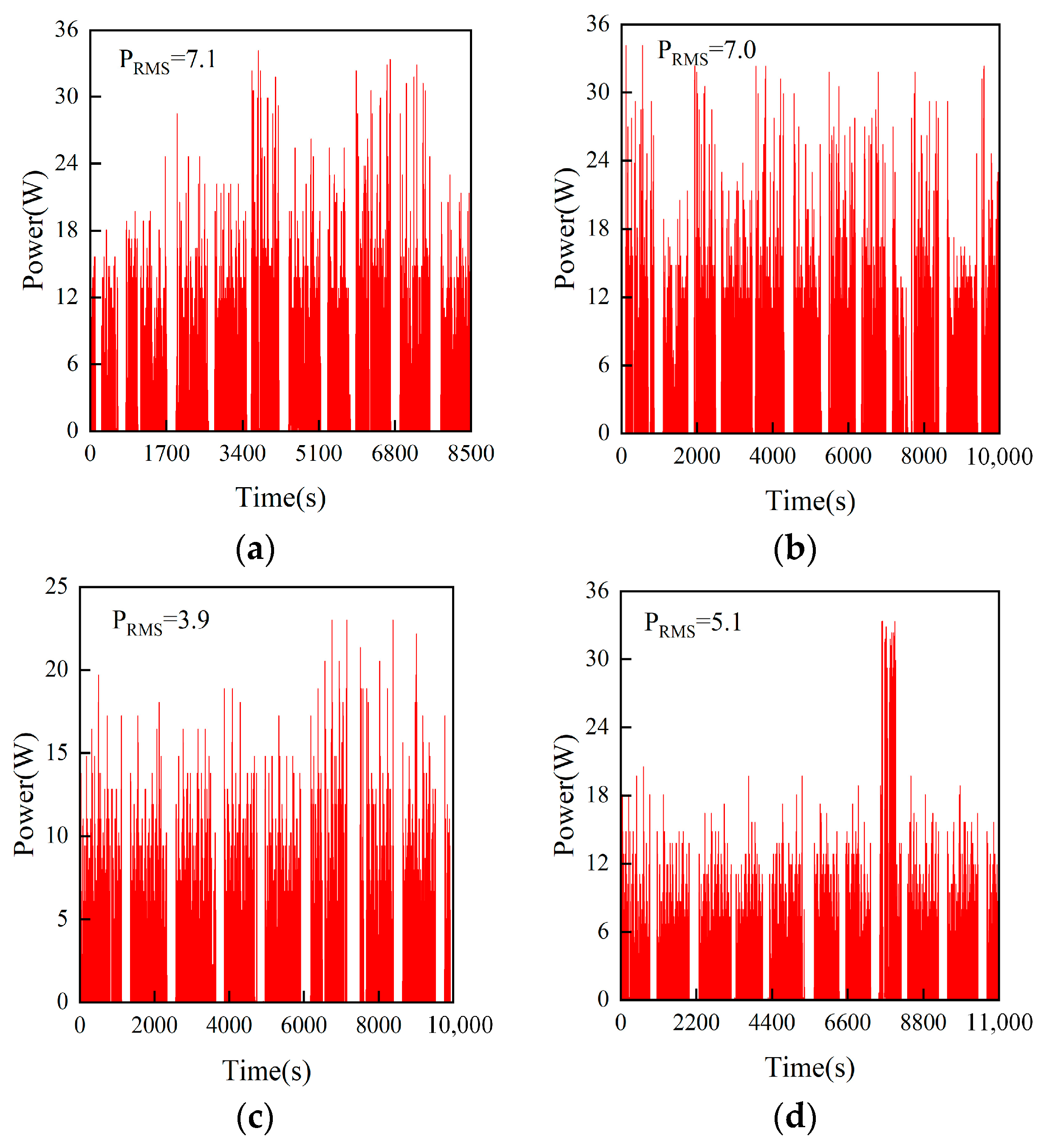
4. Results and Discussion
5. Conclusions
Author Contributions
Funding
Data Availability Statement
Conflicts of Interest
Nomenclature
| H | blade height | air density | |
| d | blade diameter | A | blade area sweeping, |
| blade thickness | m | area sweeping wind mass | |
| r | eccentric distance | v | wind speed |
| D | SVAWT diameter | blades kinetic energy | |
| damping ratio | P | blades acquired power | |
| pair 1 and 2 mesh stiffness | wind turbine airfoils | ||
| mesh gears 1 radius | mesh gears 2 radius | ||
| board rotary inertia | board angular velocity | ||
| ring gear rotary inertia | ring gear angular velocity | ||
| mesh gears 1 rotary inertia | mesh gears 2 rotary inertia | ||
| resistive torque | generator electromagnetic damping | ||
| speed constants | torque constants | ||
| generator internal resistance | generator external resistance | ||
| blade rotary inertia | blade angular velocity | ||
| DC generator rotary inertia | DC generator angular velocity | ||
| bevel gear i rotary inertia | bevel gear i angular velocity | ||
| gear i rotary inertia | gear i angular velocity | ||
| shaft rotary inertia | shaft angular velocity | ||
| gears 2 and gears 6 mesh damping | bevel gears 1 and 2 mesh damping | ||
| gears 1 and gears 7 mesh damping | bevel gears 2 and 3 mesh damping | ||
| generator input torque | damping force energy | ||
| components rotate energy | energy transfer efficiency |
Abbreviations
| BEVs | battery electric vehicles | VAWT | vertical axis wind turbine |
| PHEVs | plug-in hybrid electric vehicles | HAWT | horizontal axis wind turbine |
| CFD | computational fluid dynamics | AC | alternating current |
| SVAWT | savonius vertical axis wind turbine | DC | direct current |
References
- United Nations General Assembly Transforming Our World: The 2030 Agenda for Sustainable Development. Available online: https://sdgs.un.org/2030agenda (accessed on 23 November 2022).
- Edenhofer, O.; Pichs-Madruga, R.; Sokona, Y.; Minx, J.C. Change 2014: Mitigation of Climate Change. Contribution of Working Group III to the Fifth Assessment Report of the Intergovernmental Panel on Climate Change; Cambridge University Press: Cambridge, UK, 2014. [Google Scholar]
- Sector by Sector: Where do Global Greenhouse Gas Emissions Come from? Our World in Data n.d. Available online: https://ourworldindata.org/ghg-emissions-by-sector (accessed on 2 November 2022).
- Hardman, S.; Tal, G. Understanding discontinuance among California’s electric vehicle owners. Nat. Energy 2021, 6, 538–545. [Google Scholar] [CrossRef]
- Rezvani, Z.; Jansson, J.; Bodin, J. Advances in consumer electric vehicle adoption research: A review and research agenda. Transp. Res. Part D-Transp. Environ. 2015, 34, 122–136. [Google Scholar] [CrossRef] [Green Version]
- Jabbari, P.; Chernicoff, W.; MacKenzie, D. Analysis of Electric Vehicle Purchaser Satisfaction and Rejection Reasons. Transp. Res. Board 2017, 2628, 110–119. [Google Scholar] [CrossRef]
- Adepetu, A.; Keshav, S. The relative importance of price and driving range on electric vehicle adoption: Los Angeles case study. Transportation 2017, 44, 353–373. [Google Scholar] [CrossRef]
- She, Z.-Y.; Sun, Q.; Ma, J.-J.; Xie, B.-C. What are the barriers to widespread adoption of battery electric vehicles? A survey of public perception in Tianjin, China. Transp. Policy 2017, 56, 29–40. [Google Scholar] [CrossRef]
- Vassileva, L.; Campillo, J. Adoption barriers for electric vehicles: Experiences from early adopters in Sweden. Energy 2017, 120, 632–641. [Google Scholar] [CrossRef]
- Franke, T.; Neumann, I.; Buehler, F.; Cocron, P.; Krems, J.F. Experiencing Range in an Electric Vehicle: Understanding Psychological Barriers. Appl. Psychol. 2012, 61, 368–391. [Google Scholar] [CrossRef]
- Dumortier, J.; Siddiki, S.; Carley, S.; Cisney, J.; Krause, R.M.; Lane, B.W.; Rupp, J.A.; Graham, J.D. Effects of providing total cost of ownership information on consumers’ intent to purchase a hybrid or plug-in electric vehicle. Transp. Res. Part A-Policy Pract. 2015, 72, 71–86. [Google Scholar] [CrossRef] [Green Version]
- Does Driving Range of Electric Vehicles Influence Electric Vehicle Adoption? n.d. Available online: https://ideas.repec.org/a/gam/jsusta/v9y2017i10p1783-d113883.html (accessed on 2 November 2022).
- Zheng, P.; Fang, Z.; Li, H.; Pan, Y.; Luo, D.; Zhang, Z. Multi-objective optimization of hybrid energy management system for expressway chargers. J. Energy Storage 2022, 54, 105233. [Google Scholar] [CrossRef]
- Tan, C.; Geng, S.; Tan, Z.; Wang, G.; Pu, L.; Guo, X. Integrated energy system–Hydrogen natural gas hybrid energy storage system optimization model based on cooperative game under carbon neutrality. J. Energy Storage 2021, 38, 102539. [Google Scholar] [CrossRef]
- Electricity. Great River Energy n.d. Available online: https://greatriverenergy.com/electricity-sources/ (accessed on 2 November 2022).
- Dong, L.; Yang, F.; He, A.; Guo, Z.; Yu, J.; Zuo, J. Investigation on energy-regenerative shock absorber with adjustable damping and power for freight wagons. Energy Convers. Manag. 2022, 254, 115228. [Google Scholar] [CrossRef]
- Yu, W.; Wang, R. Development and performance evaluation of a comprehensive automotive energy recovery system with a refined energy management strategy. Energy 2019, 189, 116365. [Google Scholar] [CrossRef]
- Duan, C.; Tao, H.; Wang, C.; Chen, J.; Zhao, X.; Zhou, X. An Electric Vehicle Battery Modular Balancing System Based on Solar Energy Harvesting. In Proceedings of the 2019 IEEE Transportation Electrification Conference and Expo (ITEC), Detroit, MI, USA, 19–21 June 2019. [Google Scholar]
- Quartey, G. Generation of Electrical Power by a Wind Turbine for Charging Moving Electric Cars. J. Energy Technol. Policy 2014, 4, 19–29. [Google Scholar]
- Awal, M.R.; Jusoh, M.; Sakib, M.D.; Hossain, F.; Rashidi, M.; Beson, C.; Aljunid, S.A. Design and implementation of Vehicle Mounted Wind Turbine. ARPN J. Eng. Appl. Sci. 2015, 10, 8699–8706. [Google Scholar]
- Fathabadi, H. Possibility of Utilizing Wind Turbine to Recover a Portion of the Kinetic Energy Losses of a Car. IEEE Trans. Veh. Technol. 2019, 68, 8663–8670. [Google Scholar] [CrossRef]
- Battisti, L. Relevance of Icing for Wind Turbines. Wind Turbines in Cold Climates; Springer International Publishing: Cham, Switzerland, 2015; pp. 43–111. [Google Scholar] [CrossRef]
- Alom, N.; Saha, U.K. Influence of blade profiles on Savonius rotor performance: Numerical simulation and experimental validation. Energy Convers. Manag. 2019, 186, 267–277. [Google Scholar] [CrossRef]
- Akbari, V.; Naghashzadegan, M.; Kouhikamali, R.; Afsharpanah, F.; Yaïci, W. Multi-Objective Optimization and Optimal Airfoil Blade Selection for a Small Horizontal-Axis Wind Turbine (HAWT) for Application in Regions with Various Wind Potential. Machines 2022, 10, 687. [Google Scholar] [CrossRef]
- Eltayesh, A.; Castellani, F.; Burlando, M.; Hanna, M.B.; Huzayyin, A.; El-Batsh, H.M.; Becchetti, M. Experimental and numerical investigation of the effect of blade number on the aerodynamic performance of a small-scale horizontal axis wind turbine. Alex. Eng. J. 2021, 60, 3931–3944. [Google Scholar] [CrossRef]
- Chaudhry, H.N.; Calautit, J.K.; Hughes, B.R. Computational Analysis to Factor Wind into the Design of an Architectural Environment. Model. Simul. Eng. 2015, 2015, e234601. [Google Scholar] [CrossRef] [Green Version]
- Tjiu, W.; Marnoto, T.; Mat, S.; Ruslan, M.H.; Sopian, K. Darrieus vertical axis wind turbine for power generation II: Challenges in HAWT and the opportunity of multi-megawatt Darrieus VAWT development. Renew. Energy 2015, 75, 560–571. [Google Scholar] [CrossRef]
- Aslam Bhutta, M.M.; Hayat, N.; Farooq, A.U.; Ali, Z.; Jamil, S.h.R.; Hussain, Z. Vertical axis wind turbine—A review of various configurations and design techniques. Renew. Sustain. Energy Rev. 2012, 16, 1926–1939. [Google Scholar] [CrossRef]
- Pranta, M.H.; Rabbi, M.S.; Roshid, M.M. A computational study on the aerodynamic performance of modified savonius wind turbine. Results Eng. 2021, 10, 100237. [Google Scholar] [CrossRef]
- Al-Faruk, A.; Sharifian, A. Geometrical optimization of a swirling Savonius wind turbine using an open jet wind tunnel. Alex. Eng. J. 2016, 55, 2055–2064. [Google Scholar] [CrossRef] [Green Version]
- Ricci, R.; Vitali, D.; Montelpare, S. An innovative wind-solar hybrid street light: Development and early testing of a prototype. Int. J. Low-Carbon Technol. 2015, 10, 420–429. [Google Scholar] [CrossRef] [Green Version]
- Ricci, R.; Romagnoli, R.; Montelpare, S.; Vitali, D. Experimental study on a Savonius wind rotor for street lighting systems. Appl. Energy 2016, 161, 143–152. [Google Scholar] [CrossRef]
- Renewable Energy Resources | John Twidell, Tony Weir | Taylor & Franci n.d. Available online: https://www.taylorfrancis.com/books/mono/10.4324/9781315766416/renewable-energy-resources-john-twidell-tony-weir (accessed on 2 November 2022).
- Alam, F.; Golde, S. An Aerodynamic Study of a Micro Scale Vertical Axis Wind Turbine. Procedia Eng. 2013, 56, 568–572. [Google Scholar] [CrossRef] [Green Version]
- Torres, S.; Marulanda, A.; Montoya, M.F.; Hernandez, C. Geometric design optimization of a Savonius wind turbine. Energy Convers. Manag. 2022, 262, 115679. [Google Scholar] [CrossRef]
- Marinić-Kragić, I.; Vučina, D.; Milas, Z. Global optimization of Savonius-type vertical axis wind turbine with multiple circular-arc blades using validated 3D CFD model. Energy 2022, 241, 122841. [Google Scholar] [CrossRef]
- Sofian, M.; Nurhayati, R.; Rexca, A.J.; Syariful, S.S.; Aslam, A. An Evaluation of Drag Coefficient of Wind Turbine System Installed on Moving Car. Appl. Mech. Mater. 2014, 660, 689–693. [Google Scholar] [CrossRef] [Green Version]
- Chaudhary, Y.; Bangi, V.; Guduru, R.; Aung, K.; Reddy, G. Preliminary Investigation on Generation of Electricity Using Micro Wind Turbines Placed on A Car. Int. J. Renew. Energy Dev. 2017, 6, 75–81. [Google Scholar] [CrossRef] [Green Version]
- Abdullah, M.S.; Ishak, M.H.H.; Ismail, F. Numerical study of the 3D Savonius turbine under stationary conditions. Eng. Fail. Anal. 2022, 136, 106199. [Google Scholar] [CrossRef]
- Wei, W.; Xu, J. Lateral and Longitudinal Overlap Ratio on Starting Performance of Savonius Wind Turbine. Ind. Control. Comput. 2017, 30, 52–54. [Google Scholar]
- Morshed, K.N.; Rahman, M.; Molina, G.; Ahmed, M. Wind tunnel testing and numerical simulation on aerodynamic performance of a three-bladed Savonius wind turbine. Int. J. Energy Environ. Eng. 2013, 4, 18. [Google Scholar] [CrossRef] [Green Version]
- Wang, H.; He, C.; Lv, S.; Sun, H. A new electromagnetic vibrational energy harvesting device for swaying cables. Appl. Energy 2018, 228, 2448–2461. [Google Scholar] [CrossRef]
- Lin, T.; Pan, Y.; Chen, S.; Zuo, L. Modeling and field testing of an electromagnetic energy harvester for rail tracks with anchorless mounting. Appl. Energy 2018, 213, 219–226. [Google Scholar] [CrossRef]
- Pan, Y.; Lin, T.; Qian, F.; Liu, C.; Yu, J.; Zuo, J.; Zuo, L. Modeling and field-test of a compact electromagnetic energy harvester for railroad transportation. Appl. Energy 2019, 247, 309–321. [Google Scholar] [CrossRef]
- Hussain, M.Z.; Anbalagan, R.; Jayabalakrishnan, D.; Muruga, D.N.; Prabhahar, M.; Bhaskar, K.; Sendilvelan, S. Charging of car battery in electric vehicle by using wind energy. Mater. Today Proc. 2021, 45, 5873–5877. [Google Scholar] [CrossRef]


| Parameters | Tooth Number | Parameters | Tooth Number |
|---|---|---|---|
| gear 1 | 44 | gear 6 | 67 |
| gear 2 | 67 | gear 7 | 88 |
| gear 3 | 27 | bevel gear 1 | 51 |
| gear 4 | 27 | bevel gear 2 | 29 |
| gear 5 | 27 | bevel gear 3 | 51 |
| Parameters | Value |
|---|---|
| Diameter of input shaft | 8 mm |
| Length | 89 mm |
| Outer diameter | 68 mm |
| Rated voltage | 12 V |
| Rated speed | 2000~4000 rpm |
| No-load current | 0.2~3 A |
| Rated power | 100 W |
| Rotor inertia | 0.436 kg·cm2 |
Publisher’s Note: MDPI stays neutral with regard to jurisdictional claims in published maps and institutional affiliations. |
© 2022 by the authors. Licensee MDPI, Basel, Switzerland. This article is an open access article distributed under the terms and conditions of the Creative Commons Attribution (CC BY) license (https://creativecommons.org/licenses/by/4.0/).
Share and Cite
Zhao, Z.; Li, Y.; Zhang, B.; Wang, C.; Yan, Z.; Wang, Q. Design and Analysis of a Novel Adjustable SVAWT for Wind Energy Harvesting in New Energy Vehicle. World Electr. Veh. J. 2022, 13, 242. https://doi.org/10.3390/wevj13120242
Zhao Z, Li Y, Zhang B, Wang C, Yan Z, Wang Q. Design and Analysis of a Novel Adjustable SVAWT for Wind Energy Harvesting in New Energy Vehicle. World Electric Vehicle Journal. 2022; 13(12):242. https://doi.org/10.3390/wevj13120242
Chicago/Turabian StyleZhao, Zhen, Yongxin Li, Baifu Zhang, Changhong Wang, Zhangwei Yan, and Qingcheng Wang. 2022. "Design and Analysis of a Novel Adjustable SVAWT for Wind Energy Harvesting in New Energy Vehicle" World Electric Vehicle Journal 13, no. 12: 242. https://doi.org/10.3390/wevj13120242
APA StyleZhao, Z., Li, Y., Zhang, B., Wang, C., Yan, Z., & Wang, Q. (2022). Design and Analysis of a Novel Adjustable SVAWT for Wind Energy Harvesting in New Energy Vehicle. World Electric Vehicle Journal, 13(12), 242. https://doi.org/10.3390/wevj13120242