Article

Aspects of Foreign Object Detection in a Wireless Charging System for Electric Vehicles Using Passive Inductive Sensors

Institut für Leichtbau und Kunststofftechnik, Technische Universität Dresden, Holbeinstraße 3, 01307 Dresden, Germany
*
Author to whom correspondence should be addressed.
World Electr. Veh. J. 2022, 13(12), 241; https://doi.org/10.3390/wevj13120241
Submission received: 9 November 2022 / Revised: 2 December 2022 / Accepted: 8 December 2022 / Published: 15 December 2022

Abstract

:
If the energy transfer for charging the traction battery of an electric vehicle takes place wirelessly and with inductive components, the active area of the charging system must be monitored for safety reasons for the presence or intrusion of metallic objects that do not belong to the charging system. In the past, different concepts for such monitoring have been described. In this paper, passive inductive sensors are used and characterized based on practical measurements. With this type of sensor, the detectability of metallic foreign objects is very closely related to the characteristics of the magnetic field of the charging system. By optimizing the geometry of the sensor coils, the authors show how foreign object detection can be improved even in areas with low excitation of the foreign objects and the sensor coils by the magnetic field. For this purpose, a charging system, with which charging powers of up to 10 kW have been realized in the past, and standardized test objects are used. Furthermore, the thermal behavior of the metallic test objects was documented, which in some cases heated up to about 300 °C and above in a few minutes in the magnetic field of the charging system. The results show the capability of passive inductive sensors to detect metallic foreign objects. Based on the measurements shown here, the next step will be to simulate the charging system and the foreign object detection in order to establish the basis for a virtual development and validation of such systems.

1. Introduction

For wireless charging systems, inductive power transfer is currently prefered by standardization organizations [1,2,3,4]. Thereby, the ground assembly coil, located outside the vehicle, and the vehicle assembly coil form an ironless transformer. The magnetic field of this transformer also interacts with metallic objects that are not part of the charging system but are located in the active area between the ground and vehicle assemblies. Such objects can be parts of the vehicle but also undesired metal objects such as coins, metal foils, nails, etc. Metallic objects may become very hot within the magnetic field mainly due to eddy current and hysteresis losses. Such a heated object is a potential safety hazard if it has a temperature that is dangerous to touch at the time that the object becomes accessible, if it damages the surface on which it lies and, as a result, creates an electrical thermal issue, or if flammable materials ignite with which it is in contact. According to SAE J2954 [1] and DIN EN IEC 61980-1 [2], such hazards should be avoided by an appropriate design of the ground assembly coil or by using a subsystem for detecting metallic foreign objects.
For the detection of metallic foreign objects, different methods have been proposed in the past. They range from power electronics measurements [5,6,7,8,9,10,11,12,13,14], monitoring the free space between the coils of the power transfer system [15,16,17] up to detection of changes in the magnetic field of the charging system [18,19,20,21,22,23,24,25,26,27,28,29,30,31,32,33,34,35,36,37,38,39]. A good overview of such methods is given by [40,41,42,43]. The use of the individual methods is to some extent strongly influenced by the application area. In the automotive field, passive inductive sensors are currently favored because of the simplicity in design and that they do not require a separate signal source [42].
In this paper, practical measurements on a wireless charging system are presented and discussed. The focus is particularly on the thermal behavior of metallic foreign objects in the charging system, which characterizes the hazard risk they pose, and on the detection of such objects with passive inductive sensors, taking into account the real ambient conditions in the charging system. When using inductive sensors, the characteristic of the magnetic field of the charging system is decisive for the excitation of both the foreign objects and the sensor coils. In a wireless charging system, the main points to be considered are as follows:
  • The magnetic field of the charging system is not homogeneous.
  • The magnetic field of the charging system is much stronger than that of the foreign objects.
  • Typically, differential sensors are used whose output signal represents the gradient of the magnetic field.
These points have been discussed individually in the past and led to a gradual change in the design of the sensor coils. The evolution of passive inductive sensors is discussed in more detail in Section 5 based on the findings from the practical measurements. As one of the results of this work, a new sensor design has emerged that improves the detection of metallic foreign objects, especially at the points where the determining component of the magnetic field of the charging system takes the value zero and thus typically no objects are detectable. Further results of the investigations are the illustration of the influence of the material of the foreign objects and the different sensitivity of the sensor coils depending on the relative size and position of coil and foreign object to each other.
For the practical measurements, an experimental setup is used with which charging powers of up to 10 kW have already been transmitted in previous projects [44,45]. However, only the ground assembly of the charging system is used in the measurements. Why? In [1], it is specified that the detection of metallic foreign objects is mainly the task of the ground assembly and that it is important to detect foreign objects both prior to and during power transfer. This means that the detection of metallic foreign objects should work both with and without the vehicle assembly. The use of the ground assembly without the vehicle assembly thus represents an initial measurement scenario in which the detection of metallic foreign objects should be possible. This scenario can be extended by the vehicle assembly and a vehicle or vehicle replica. However, there are many boundary conditions that influence the results of the measurements. In the case of the positioning of the vehicle assembly, these are, for example, the distance in the z-direction, the offset in the x- and in the y-direction, and the rotation in the three spatial axes (roll, pitch and yaw). Other factors include the design of the vehicle and vehicle assembly, and the materials used. This leads to a great number of measurements in the experiment, which require a lot of time.
Against the backdrop of a very sharp rise in time required, practical tests in connection with automated driving are also currently being discussed. The European projects ArchitectECA2030 [46] and AI4CSM [47] are manifestations of this process. One strategy to solve this time problem is simulation and thus virtual development and validation. In the course of testing this strategy for wireless charging systems, the charging system and foreign object detection will be simulated in a second step. With the help of the measurement results presented here, the simulation models used can be validated. With the valid models, new scenarios can subsequently be simulated, such as the presence of the vehicle assembly. Since typically only computational equipment is needed to run the simulations, this approach is usually cheaper and faster than the practical experiments.

2. The Ground Assembly of the Used Charging System

2.1. Mechanical and Electrical Parameters

The ground assembly used in the experimental setup consists of a flat rectangular coil whose reactance is compensated by two capacitor blocks connected in series. This series resonant circuit is driven by two power transistors in a half-bridge module, which gets its energy from a DC link. The latter is fed either from a three-phase stand-alone network designed for up to 110 kVA coupled with a rectifier, or from a 3 kW DC source for smaller charging powers. In Table 1 the main parameters of the resonant circuit of the ground assembly are collected. As shown in Figure 1, the used coordinate system was chosen to have its origin at the center of the ground assembly coil. The x- and y-axes are in a plane with the ground assembly coil and parallel to the sides of the coil, which is narrower in the x-direction than in the y-direction. The z-axis is perpendicular to the largest spatial dimensions of the ground assembly coil, with positive coordinates assigned to the areas above the coil.
The values of the flat coil and the compensation capacitors as well as the resonance frequency were measured using an Agilent LCR meter type E4980A. The inductance and capacitance values were captured over the entire operating frequency range of the charging system (79 kHz to 90 kHz according to [1,3,4]). The quality factor of the flat coil is almost constant within the operating frequency range of the charging system and reaches its maximum value in the frequency range between 81.5 kHz and 81.9 kHz. The largest value of the quality factor of the compensation capacitors was measured with 7846 at a frequency of 7.4 kHz. In the operating frequency range of the charging system, the quality factor drops roughly linearly from 3316 to 2822.
The current flowing in the resonant circuit of the ground assembly can be considered to be sinusoidal. In previous works [44,45], a current of 50 A rms to 65 A rms was used in the resonant circuit of the ground assembly at a transfered power of 3.6 kVA. At a power of 7.2 kVA, the current varied between 50 A rms and 75 A rms, and at 11 kVA between 50 A rms and 95 A rms. The required value of the current was mainly influenced by the design of the vehicle assembly, the current state of charge of the battery and the distance between the ground and vehicle assemblies.
To achieve low switching losses of the power semiconductors, especially zero voltage switching, the load must exhibit inductive behavior. In a series resonant circuit, this is the case above the resonant frequency. For this reason, the measurements shown below were carried out at a switching frequency of 80 kHz.

2.2. The Magnetic Field of the Ground Assembly

For the investigation of the sensor coils and as well for the documentation of the thermal behavior of test objects it is necessary to know how the magnetic field is formed around the ground assembly coil. For example, the standards SAE J2954 [1] and DIN CLC IEC/TS 61980-3 [3] define that objects for testing should be placed at positions where the magnetic field of the ground assembly is strongest. For this purpose, ref. [3] refers to the highest flux density of the magnetic field as reference parameter. In [1] no specific parameter is given, but reference is made to the locations with the largest magnetic field component parallel and perpendicular to the surface of the ground assembly package, which must be specified and marked by the manufacturer.
Therefore, in the first step of the investigations carried out here, the magnetic field of the ground assembly coil is measured. Since a coil without a housing is used, the measurements are made in an xy-plane of the coordinate system and thus parallel to the largest spatial dimensions of the ground assembly coil. In this case, the magnetic field component perpendicular to the surface of the ground assembly is the z-component and can be measured directly. The magnetic field component parallel to the surface of the ground assembly, i.e., within an xy-plane, is composed of the respective x- and y-components. If the magnetic flux density is used as reference parameter, the amplitude of the in plane component can be calculated as follows:
B x y = B x 2 + B y 2
Figure 2 shows the values measured along the x-axis of the coordinate system at y = 0   mm at currents of 4 A rms and 10 A rms in the ground assembly coil. The flux density of the magnetic field of the ground assembly was measured using a measurement device from Hioki type FT3470-52 with a probe of 3 cm2 measuring area. At a current of 4 A rms, the instruments measurement range of 200 μT for the magnetic flux density was used. Thus, the measurements can be made with the highest possible accuracy. At a current of 10 A rms, the maximum flux density of the measuring probe of 500 μT at 80 kHz alternating frequency of the field is reached according to the manufacturer’s specifications. The measuring probe was moved on the carrier plate and was thus located with its bottom side at the coordinate z = 13   mm . The base area of the probe’s housing has an edge length of 26 mm. In height, the housing is 27 mm.
In the left diagram in Figure 2, it can be seen that the component in the xy-plane has a zero at x = 0   mm . On both sides of the y-axis of the coordinate system the x-component has the opposite direction. A similar situation can be seen for the z-component in the right diagram in Figure 2, where the zeros are located at x ± 250   mm . This means that the z-component has a different direction in the inner area of the ground assembly coil than outside.
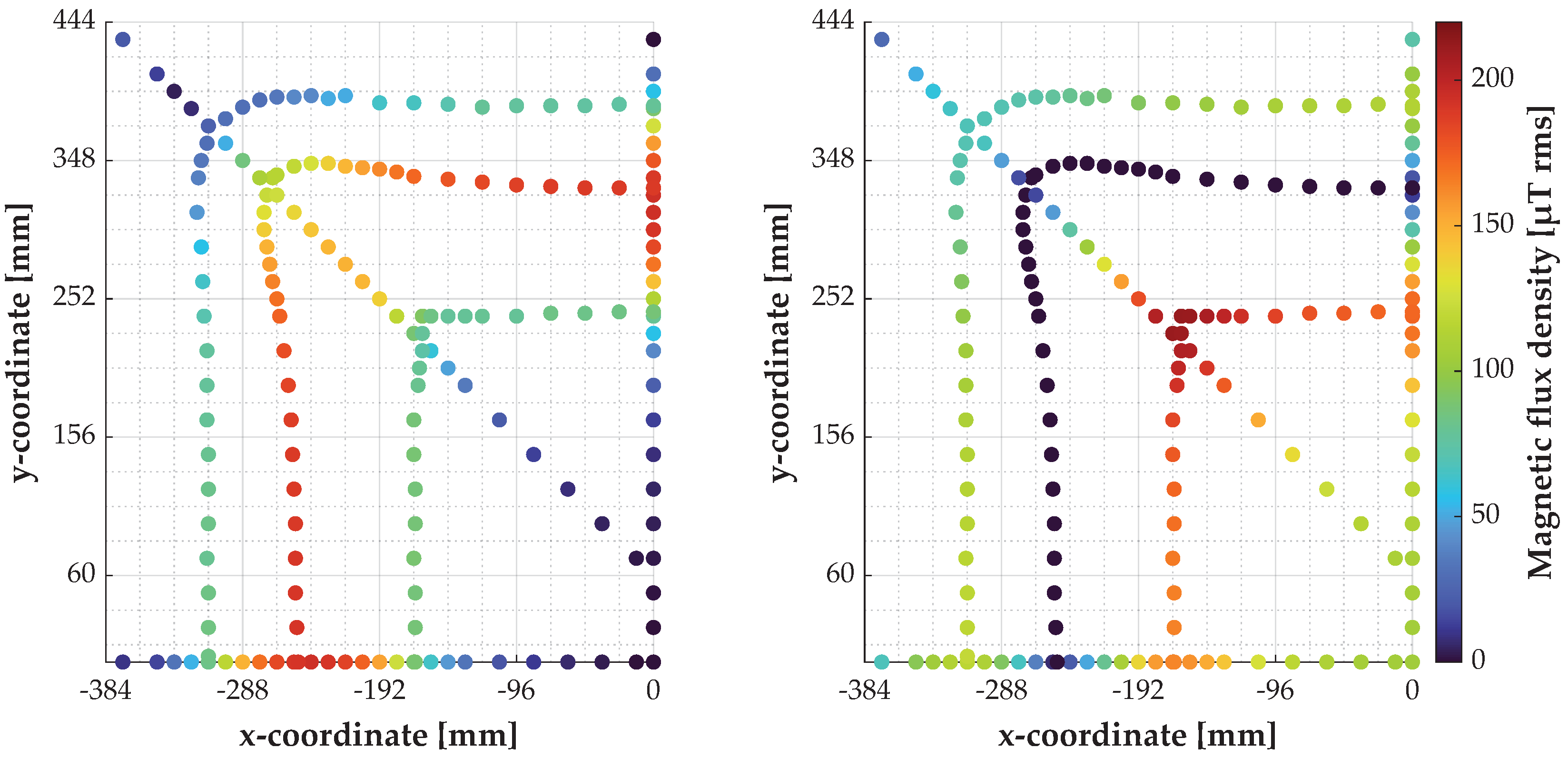
Additionally, the magnetic flux density was measured in the upper left quadrant of the ground assembly coil at other characteristic points (Figure 3). Among them are the paths of the extrema of the z-component and its zero crossing. The diagonal path across the corner of the ground assembly coil was measured mainly to determine the magnitude of the magnetic field component in the xy plane, since this is composed of the x and y components and cannot be read directly from the instrument, and thus to identify the locations of maximum flux density.
Figure 3 shows that the x- and y-components of the magnetic flux density have a value of zero at the coordinate origin. Above the y-axis of the coordinate system the x-component has the value zero—above the x-axis, this applies in the same way to the y-component. The component in the xy-plane has its maxima approximately in the middle above the wires of the ground assembly coil, directly above the x- and y-axis of the coordinate system, respectively. The maximum of the z-component occurs near the corner inside the ground assembly coil (see also Table 2).

3. Metallic Foreign Objects in the Magnetic Field of the Ground Assembly

Metallic objects located in the magnetic field of the ground assembly coil interact with it and heat up mainly due to eddy current and hysteresis losses. This heating is used at the same time in the standardization as a basic test criterion for the entire wireless charging system or subsystems thereof. Among other things, test objects, temperature limits, cooling times and test procedures are defined in [1,2,3] for this purpose. Test objects listed include coins, nails and metal foils or sheets. However, if the test objects are compared in detail, especially dimensions and material, there are only a few similarities. Therefore, the test objects listed in Table 3 were used for the measurements within the scope of this work.
In [1] as well as in [2,3], the upper temperature limit for the test objects used is specified to be 80 °C—although a test object may also exceed this limit if it cools down to lower values again within a period of 60 s after the power transfer has stopped. In accordance with SAE J2954 [1], the test duration with an active magnetic field is limited in time to 5 min and 10 min, respectively—according to DIN CLC IEC/TS 61980-3 [3] the tests are performed until a thermal equilibrium is reached.
The thermal behavior of test objects 1 to 6 was measured at the position with maximum z-component of the magnetic flux density (see Table 2) and in case of test objects 7 and 8 at one of the positions with maximum xy-component of the magnetic field component ( x = 240   mm , y = 0   mm ) [1]. The test objects were aligned with their longest dimension parallel to the x-axis of the coordinate system. For the temperature measurements, currents of 50 A rms and 80 A rms, respectively, were set in the resonant circuit of the ground assembly. The specimens were exposed to the magnetic field for a time of 5 min. After that, the charging system was turned off and the time of cooling was measured. A ceramic tile (300 mm × 300 mm × 7 mm) was placed between the test objects and the carrier plate as thermal protection. The test objects were thus positioned approximately at z = 20   mm .
For the temperature measurements fiber optic sensors and the measuring system from Optocon type FTMS with measuring modules type Fotemp-2K were used. The temperature sensors were placed in the center of the test object. Since the measuring system is only designed for temperature measurements up to 300 °C, the measurement was terminated prematurely by turning off the energy source when the test object had exceeded this limit. The measured values are shown in Table 4.
With test objects of the same shape, approximately the same size but made of different materials, the influence of the material is clearly visible. This applies especially to the coins and metal foils. The measured values in Table 4 also indicate why the standardization bodies favor, for example, the 0.05 € coin over the 2 € coin included in earlier versions of SAE J2954, or why foils and sheets made of aluminum and not copper were specified as test objects in the standards.
As can be seen from the measurement results, the test objects heat up to over 70 °C at currents that are practically relevant for energy transfer, which makes their handling in the test difficult or impossible. Therefore, the subsequent measurements were carried out only at a current of 10 A rms in the ground assembly coil.

4. Sensor Coils for the Detection of Metallic Foreign Objects

Within the scope of the measurements, passive inductive sensors of different shapes are to be investigated. These essentially consist of conductor loops which are stimulated by both the magnetic field of the ground assembly coil and the magnetic fields around the test objects in which eddy currents flow. According to the law of induction, the voltage induced in the sensor coils is proportional to the time variation of the magnetic flux density penetrating the area of the conductor loop. Since the magnetic field of the ground assembly coil of a wireless charging system is much stronger than that of the test objects and the sensor coils are only intended to detect the presence or absence of metallic foreign objects, they are typically designed as differential sensors and thus measure the gradient of the magnetic field. In this way, ideally, the effect of the magnetic field of the ground assembly coil can be eliminated in the area of the sensor coil and only the influence of the foreign object is captured. In practice, this effect is achieved by a clever choice of the size and orientation of the conductor loops of a sensor coil, whereby the inhomogeneities of the magnetic field of the ground assembly coil must also be taken into account.
In order to be able to design and position the sensor coils flexibly, a carrier plate was designed and used. Its surface is crisscrossed with 2 mm wide and deep grooves, which form a square grid with 24 mm edge length parallel to the coordinate axes (Figure 1). In relation to the coordinate system used, there are 16 grid elements on each side of the y-axis and 18.5 grid elements above (positive y-direction) the x-axis. The tested sensor coils were made by inserting enameled copper wire with a diameter of 0.3 mm and therefore have dimensions corresponding to multiples of this grid. To describe the used sensor coils, a type specification in the form n × l × w is used, which indicates that the coil consists of n sections (conductor loops with one turn each) of identical size, each with a length of l × 24   mm and a width of w × 24   mm . The length is always given in the x-direction and the width in the y-direction of the coordinate system. The conductor loops are oriented in such a way that the output voltage of the sensor coil ideally has a value of zero without the presence of a foreign object (offset voltage). The coil geometries listed in Table 5 were used for the measurements. Figure 4 shows as an example the schematic structure of the sensor coils 2 and 6. During the measurements, the sensor coils were at a height of z = 11   mm and thus about 2 mm below the test objects.
The measurement signals were acquired using a Keysight MSOX4024A oscilloscope. A differential probe type N2818A was used to measure the sensor voltage and a probe type N2790A was used to measure the DC link voltage. The current in the resonant circuit of the ground assembly was measured using a PEM Rogowski coil type CWTMini HF06B. For the measurements, a current of 10 A rms was fed into the resonant circuit of the ground assembly. The phase angle of the sensor voltages was measured with respect to the current flowing through the ground assembly coil.
Since the magnetic field of the ground assembly coil is not homogeneous, a location dependence of the sensor coil output voltages is to be expected during the measurements.

4.1. Signal Interference Due to Capacitive Coupling

During initial test measurements, it was found that the sensor coils produce varying levels of interference voltage depending on their design, with an amplitude that in some cases was significantly higher than that of the expected useful signal. Therefore, in a first step, the interference voltage was measured as a function of the coil position and the coil shape.
The interference voltage is coupled into the sensor coils synchronously with the switching edges of the input voltage of the series resonant circuit of the ground assembly. The causes shall be parasitic capacitances between the ground assembly coil and the respective sensor coil and the slew rate of the input voltage of the series resonant circuit. Measurements of the slew rate between 10% and 90% of the maximum amplitude have shown an average value of 1.2 V/ns. If the gradient is calculated continuously over the recorded measured values, the maximum value was 1.5 V/ns when averaged over five successive values.
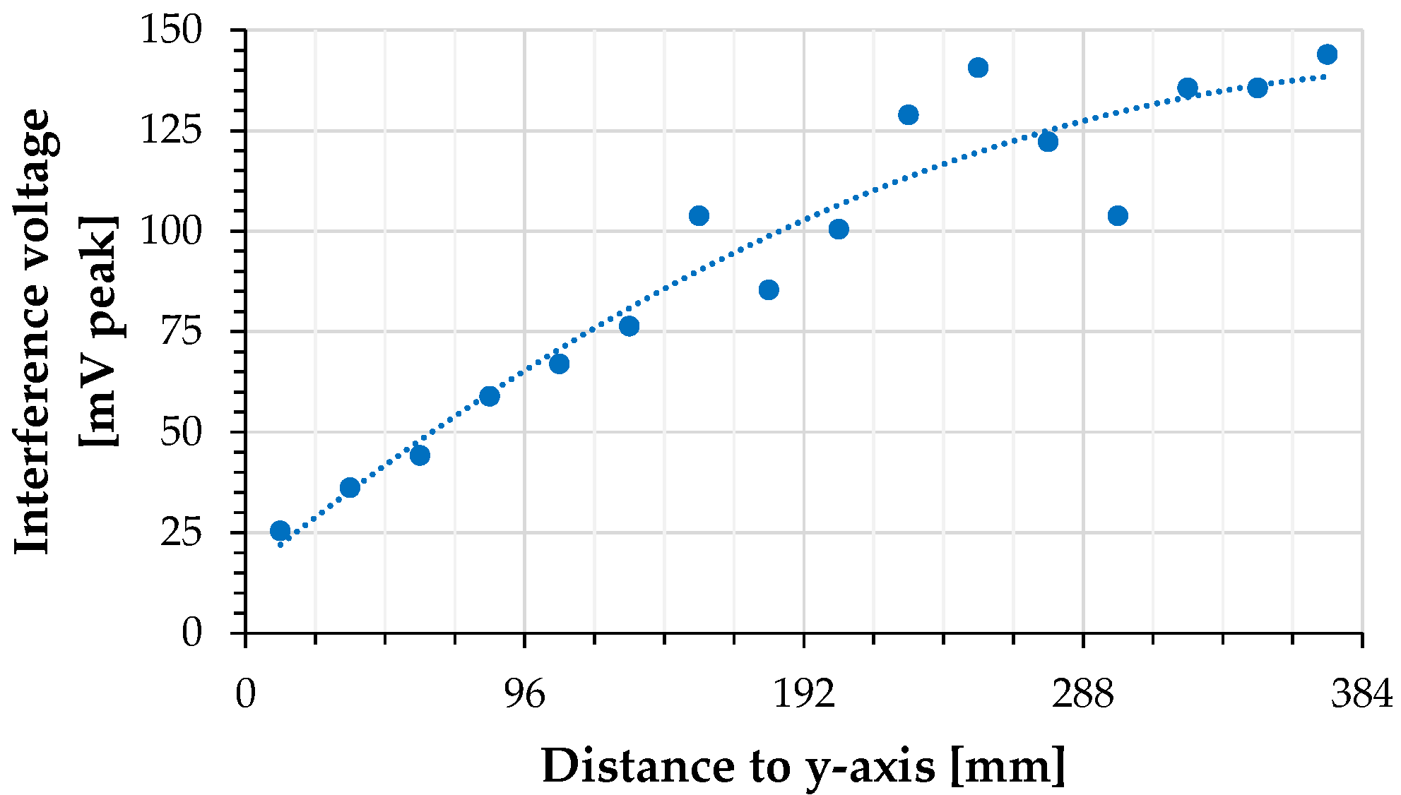
Figure 5 shows the results obtained for the position-dependent detection of the interference voltage. For this purpose, sensor coil 1 was placed above the x-axis of the coordinate system and the voltage induced in it was measured. The two conductor loops of the sensor coil were arranged at different distances symmetrically to the y-axis of the coordinate system, taking into account the symmetry of the magnetic field of the ground assembly coil. The trend line shows an increasing voltage amplitude with increasing distance of the sensor coils from the y-axis. The largest deviations of the measured values from the trend line occur above the flat coil and at its inner edge—the hot end of the ground assembly coil.
In the Table 6 the maximum amplitudes of the interference voltages for different types of sensor coils are shown. It can be seen that the amplitude of the interference voltages does not change proportionally to the area of the sensor coil, but is strongly dependent on the shape of the respective coil.
The interference voltages are in the frequency range above 1 MHz and thus have significantly higher frequencies than the useful signals. Therefore, a 6th order active low-pass filter with Bessel characteristics was developed and used to measure the feedback effects of the test objects on the sensor coils. The low-pass filter has a 3 dB cutoff frequency of 240 kHz, attenuates the high-frequency interference signals and amplifies the useful signals at 80 kHz by a factor of 20 (26 dB). The amplification of the useful signal improves the signal-to-noise ratio for the measurement with the oscilloscope, but is taken into account and removed during the acquisition. This means that the signal values given in the following sections correspond to the level at the input of the filter and the output of the sensor coils, respectively. The signal propagation time of the filter of 2 μs was included in the measurements and corrected as part of the post-processing of the signals.

4.2. Influence of the Magnetic Field of the Ground Assembly on the Sensor Coils

Ideally, the sensor coils should fade out the magnetic field of the ground assembly coil and only detect the influence of metallic foreign objects. Therefore, differential coils are used, which are constructed and positioned to take advantage of the symmetry properties of the ground assembly coil and its magnetic field. In Figure 6, the voltage induced in a single 24 mm × 24 mm sized conductor loop is shown while it is at different positions above the x-axis of the coordinate system. In this context, the visualization of negative signal amplitudes is a qualitative consideration of the phase angle of the measured signal, which can only be interpreted in relation to the positive signal amplitudes in the same diagram.
From these diagrams, the induced voltage in larger conductor loops can be derived by summing up the measurement results over the corresponding area of the conductor loop.

4.3. Feedback Effects of Metallic Foreign Objects on the Sensor Coils
In [27], the authors simulated the functionality of their proposed sensor coils. Starting from an offset voltage of 7.5 mV, they show an amplitude of the output voltage of the sensor coils that increases steadily with the number of coins used as foreign objects. With eight coins, they reach a signal amplitude of 22.4 mV. However, the increase is not linear with the number of coins and the authors do not provide any information on how the coins were placed relative to the sensor coil and the magnetic field.
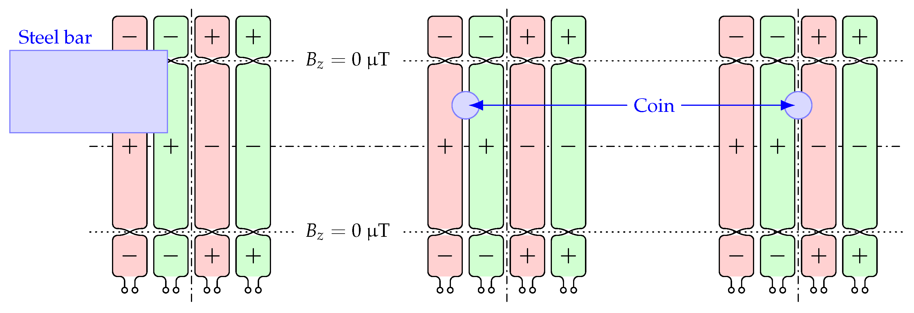
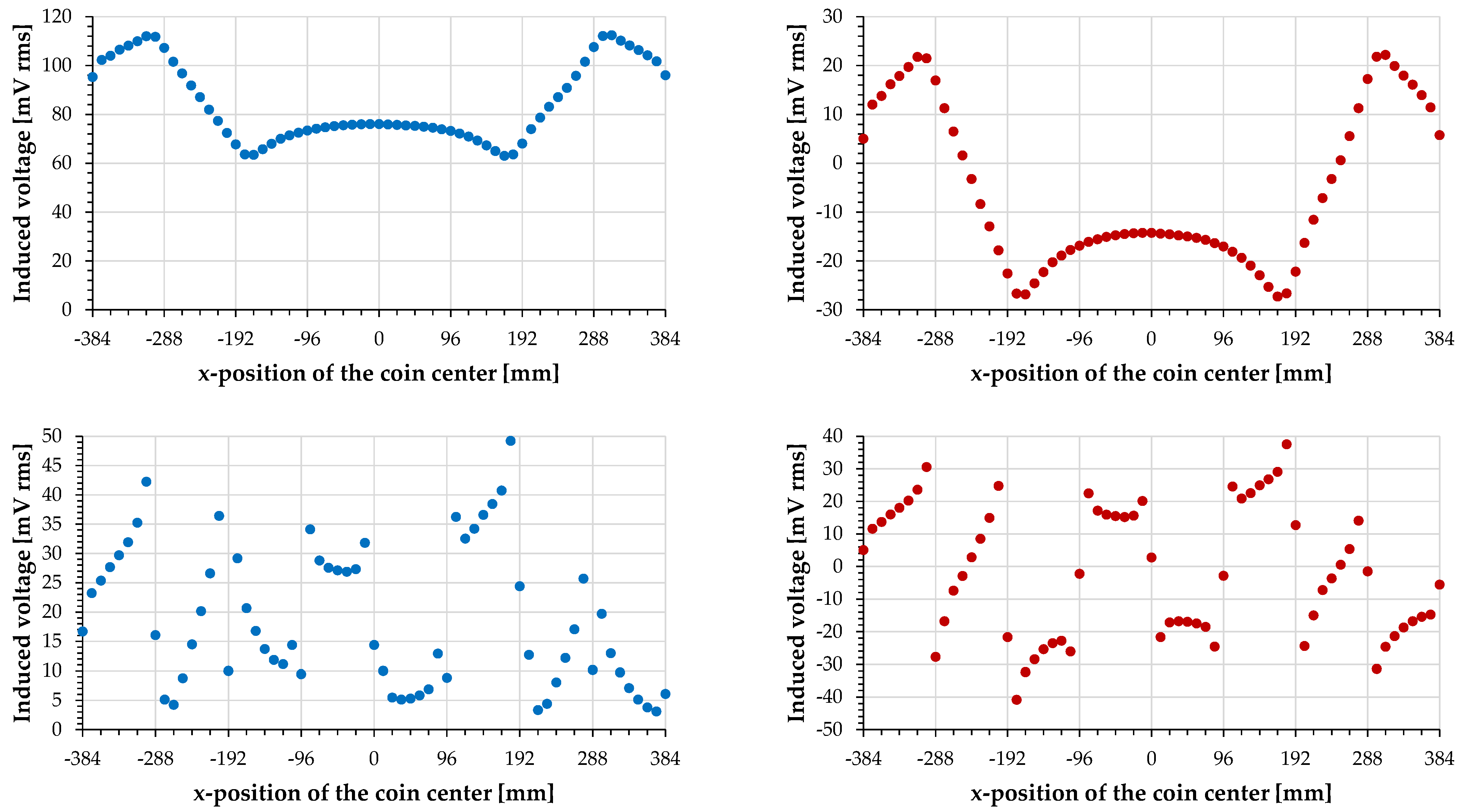
Due to the inhomogeneity of the magnetic field of the ground assembly, the influence of the test objects was investigated depending on their position. In Figure 8 the results for sensor coils 2 and 6 with a 0.05 € coin as test object are shown as representative examples. In the case of sensor coil 2, the coin was moved parallel to the x-axis along the coordinate y = 24   mm (see also Figure 4). If the coin would be moved along the coordinate y = 24   mm , its influence on the sensor coil would ideally be equal in magnitude but would have the opposite sign. In the case of sensor coil 6, the coin was moved parallel to the x-axis along the coordinate y = 0   mm (Figure 7).
If the sensor coil without a test object produces an output voltage that is smaller than the influence of the test object, then not only the amplitude of the sensor signal but also its phase angle must be measured, since a phase shift occurs when the zero line is crossed (see Figure 8 bottom). If the output voltage, which can be measured without a foreign object, is higher, the phase angle of the sensor signal changes only in a small range and does not show any discontinuities. The influence of the test object in such a case can be calculated easily as the difference between the measured signal value and the offset value (see Figure 8 top).
Figure 8. Output signals of the sensor coils depending on the position of the test object 1 (top) Signals of the sensor coil 2 (bottom) Signals of the sensor coil 6 (left) Actual measured signal amplitudes (right) Calculated influence of the test object taking into account offset voltage and phase angle.
Wevj 13 00241 g008
In practice, the accuracy of the measurement with respect to both the amplitude value and the phase angle decreases as the actual measurable signal amplitude approaches zero, since noise and other interferences then have an increasing influence.
When the post-processed measured values reach the zero line, the test object is no longer detectable, because then the output voltage of the sensor coil is identical to its offset voltage—the value of the output voltage that can be measured even without the foreign object. This is the case in the bottom right diagram in Figure 8 with the coin located between two oppositely aligned conductor loops (see also Figure 9), since in these cases the sensor coil is symmetrically stimulated. As it can be seen in the two diagrams on the right in Figure 8, the coin is also undetectable at the locations where the z-component of the magnetic field of the ground assembly coil takes the value zero ( x ± 250   mm ).
As a comparison to the coin shown so far, the steel nail shall now be used. For the measurements, the steel nail was aligned with its largest dimension parallel to the x-axis and moved along the coordinate y = 24   mm (Figure 10). The left diagram in the Figure 11 shows that the influence of the nail on the sensor coil 2 is significantly smaller but comparable in its position dependence to that of the coin in Figure 8. In addition, the voltage induced in the sensor coil by the presence of the nail has the opposite polarity compared to the coin if both objects are in the same position relative to the sensor coil.
The right diagram in the Figure 11 shows the influence of the test object 7—the steel bar—when it is moved in y-direction above the y-axis ( x = 0   mm ) over the sensor coil. The test object was aligned with its longest dimension in the direction of the y-axis. Here it can be seen that detection is not possible in two situations: firstly, when the test object is positioned exactly in the center of the sensor coil and secondly, when the test object covers about half of each of the two conductor loops of the sensor coil. In the first case the entire sensor coil is symmetrically stimulated, in the second case the respective affected conductor loop.
For small test objects, the influence at the edge within a conductor loop is larger than in its center. This effect occurs not only in the x-direction (Figure 8 bottom) but also in the y-direction, if the sensor coil is significantly larger than the test object. Figure 12 shows this using the example of sensor coil 7 and test object 1. To improve the spatial impression of the representation, additional values were calculated between the captured measurement points and displayed as a grid using MATLAB and a spline interpolation.
As already shown in Figure 8 and Figure 11, the test object is not detectable at the points where the z-component of the magnetic field has the value zero. However, in the design of the sensor coils, only the axial symmetry of the magnetic field of the ground assembly coil has been considered so far. On both sides of its zero value, the z-component of the magnetic flux density has opposite signs. Thus, in a conductor loop of the sensor coil covering the zero line, partial voltages with opposite phases are induced which compensate each other. If the orientation of the conductor loop of the sensor coil is also reversed at the zero line of the z-component of the magnetic flux density, then the voltages induced in the sensor coil are added.
Therefore, a modified version of the sensor coil 2 was manufactured and tested. Its structure does not fit into the scheme used so far, because conductor loops with different sizes were chosen. The offset voltage of the implementation of the modified sensor coil was 87 mV rms. The left image in Figure 13 shows the ideal shape of such a sensor coil—the right one the version realized for the measurements based on the grid of the carrier plate.
Figure 14 shows the feedback effects of the 0.05 € coin and the steel nail on this sensor coil. During the measurements, the test objects were aligned with their largest dimension parallel to the x-axis and moved along the coordinate y = 24   mm . The main difference to the previous results is in the area around the x-coordinates ±250 mm, where the z-component of the magnetic field reaches zero, but the test objects are still detectable.

5. Discussion

The measurement results shown in the previous sections have minor asymmetries. These are caused by mechanical tolerances, since the inductive main components of the system under consideration were all manufactured by hand. The alignment of the ground assembly coil and the sensor coils to each other was also conducted manually. A significant symmetry deviation is caused by the electrical contact of the inner winding end of the ground assembly coil. Therefore, measurements were limited to y-coordinates greater than or equal to −180 mm. Mechanical tolerances are also the reason for the differences in the offset voltages of the sensor coils.
In this work, a ground assembly with a flat rectangular coil was used. The design and arrangement of the individual conductor loops of the sensor coils for foreign object detection are mainly influenced by the magnetic field of the ground assembly coil. If a coil with a different magnetic field is used in the ground assembly, e.g., a double-D coil, then the shape and arrangement of the sensor coils must be adapted.
The capacitively coupled interferences detected in the measurements can be reduced not only by filtering the measurement signal as described above, but also by reducing the slope of the edges of the voltage applied to the resonant circuit of the ground assembly. This can be accomplished by adding more passive reactances to the coupling network between the power electronics and the ground assembly coil, to give the coupling network a low-pass characteristic. In this way, an approximately sinusoidal waveform of the voltage can be achieved.
Due to practical limitations, some of the measurements were not carried out under real operating conditions of the charging system.These limiting conditions include limits for the used measurement technology but also physical reasons, such as the heating of metallic test objects in the magnetic field. However, the necessary values for real operating conditions can be derived from the measured values.

5.1. The Magnetic Field of the Ground Assembly

The magnetic flux density of the ground assembly coil was measured at currents of 4 A rms and 10 A rms. It clearly shows, according to Ampère’s law, a proportionality to the flowing current. By using this linear relationship, the flux densities shown in Table 7 can be calculated for operating currents of the charging system between 50 A rms and 100 A rms.

5.2. Thermal Behavior of the Test Objects

When recording the thermal behavior of the test objects, a thermal equilibrium as specified in [3] as termination condition for the definied tests was not observed in any of the cases at an ambient temperature in the range of 25 °C to 30 °C (Figure 15). There are three main reasons for this:
  • The measurement period was limited in time and thus apparently too short.
  • The premature termination of the test of individual test objects if they have heated up very quickly and very strongly, such as the steel nail.
  • The permanent emission of thermal energy of the test objects to their environment
The latter effect was particularly noticeable with test object 7, i.e., the test specimen with the largest heat capacity and at the same time large surface area. The measurements indicate that longer test times are necessary to achieve a thermal equilibrium. However, the measurement setup and the measurement technology must then cover a wide temperature range, since the test objects heat up very differently.
With a current of 50 A rms flowing through the ground assembly coil, test objects 1 through 4 and 6 would pass the test sequence as defined for charging systems without a foreign object detection in [1]—but test objects 5, 7, and 8 would not. At a current of 80 A rms, the charging system does not pass this test sequence with any of the test objects. This means that the wireless charging system used here would necessarily have to have a foreign object detection system.

5.3. Feedback Effects of Metallic Foreign Objects on the Sensor Coils

The voltages induced in the sensor coils by the magnetic field of the ground assembly coil and the eddy currents driven in the test objects are determined, according to the law of induction, by the time variation of the part of the magnetic flux density that penetrates the corresponding surface. This results in fundamental properties of passive inductive sensors. Due to their arrangement, the sensor coils used here are mainly influenced by the z-component of the magnetic field.
The magnetic field generated by the eddy currents in the respective test objects is directed in the opposite direction to its cause and damps the magnetic field of the ground assembly coil. In the case of dia- and paramagnetic metallic materials, it is mainly the damping of the magnetic field of the ground assembly coil that determines how well the test objects can be detected. For ferromagnetic materials, two effects compete with each other. One is the damping of the magnetic field of the ground assembly coil due to the magnetic field that is formed as a result of the eddy currents. On the other hand, ferromagnetic materials also boost the magnetic field of the ground assembly coil because they conduct the magnetic flux due to their very low magnetic resistance and thus influence the magnetic field in their direct vicinity. A direct comparison of the measurement results shows that the second effect prevails for test objects 8 and the first effect for test object 1 (compare also Figure 8, Figure 11 and Figure 14). With regard to detectability with passive inductive sensors, test object 1 thus behaves like the other coins, although it has a core made of steel.
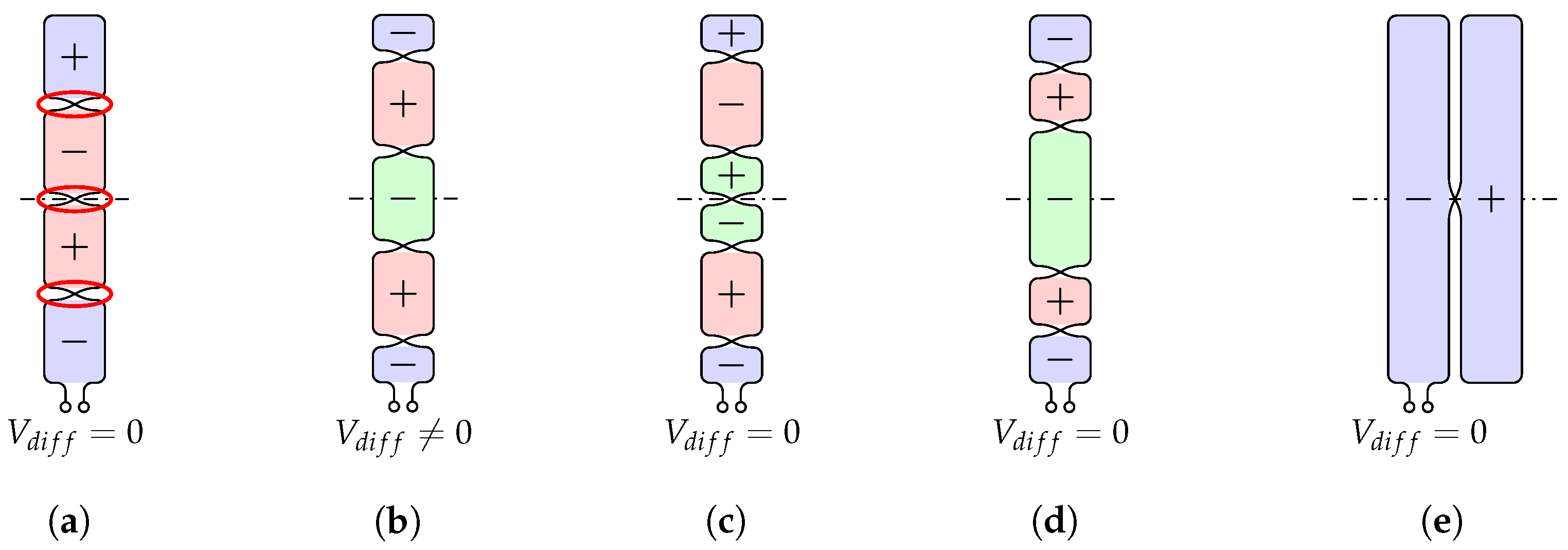
Passive inductive sensors are already known in various forms from other publications. The results of this investigation are suitable for deriving recommendations for the design of such sensors. A significant problem in the detection of the test objects is a possible symmetrical stimulation of the sensor coil by the test object (Figure 8, Figure 11 and Figure 16a). In this case, the influence of the test object is faded out as well as the magnetic field of the ground assembly coil. This effect is also described, among others, in [26] for so-called blind spots between individual conductor loops in a sensor array and in [27] for the dead zone between two conductor loops of a sensor coil. In both publications, the authors propose a second layer with the same sensor coils but shifted in their position to solve this problem (Figure 16b). In this case, however, due to the symmetry properties and the inhomogeneity of the magnetic field of the flat rectangular ground assembly coil, a significantly non-zero output voltage would be induced in the second sensor coil, because one of the conductor loops overlaps the symmetry axis and thus other conductor loops with the same induced voltage are no longer oriented in opposite directions.
This limitation can be addressed in several ways. First, it would be possible to take into account the symmetry of the ground assembly coil. In this way, the voltages induced in the conductor loops located on both sides of the symmetry axis compensate for each other (Figure 16c). However, in this way, the insensitive area of the first sensor coil, which is located on the symmetry axis, cannot be compensated. A second option is to match the areas of the sensor coil’s conductor loops in the second plane so that the voltage induced in the conductor loop shown in green compensates for the voltages induced in the conductor loops shown in red and blue (Figure 16d). Another possibility for the space dimension shown arises when the conductor loops of a sensor coil completely cover the ground assembly coil (Figure 16e), as proposed for example in [21,22,31]. Here, the sensing coil is formed by at least two conductor loops arranged in parallel. However, the problem of symmetrical stimulation at the symmetry axis basically remains in the second spatial dimension of the ground assembly coil (Figure 17 left).
This could be almost completely avoided by arranging another group of sensor coils rotated by 90 on a second layer, as proposed e.g., in [21]. In this solution, the test objects would be undetectable only in the center of the ground assembly coil. Another solution was proposed in [31]. Here, the two inner sensor coils were arranged asymmetrically with respect to the ground assembly coil (Figure 17 right). If the conductor loops of the sensor coils are only very narrow compared to the dimension of the ground assembly coil, then the unbalance of the magnetic field between the conductor loops of one of the sensor coils is only small and can be neglected. As the right diagram in Figure 11 shows, a foreign object must be centered above the coil in order not to be detected. In the case of the asymmetrically arranged sensor coils in the right image in Figure 17, this is not possible for both sensor coils at the same time if the object overlaps one or both of the coils and is small with respect to the ground assembly coil. However, this effect becomes less effective with increasing size of the foreign object, because then the influence of the foreign object becomes more and more uniform in the area of the sensor coils and thus the stimulation of the sensor coils becomes more and more symmetrical.

5.4. Improved Detectability of Foreign Objects by Using a Modified Sensor Coil

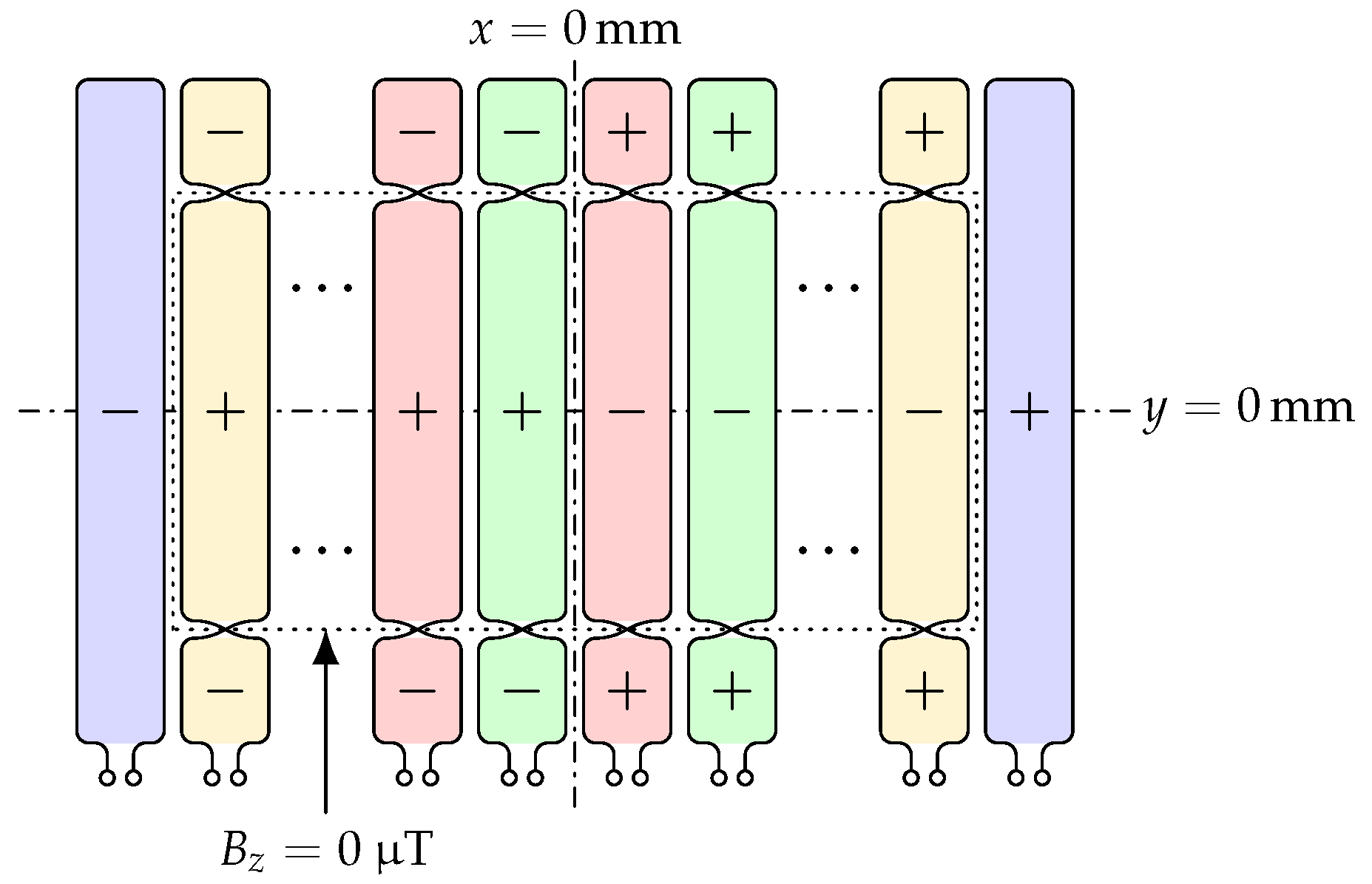
As the results for the modified sensor coil 2 show, the detectability of foreign objects can also be improved in the region where the z-component of the magnetic field takes the value zero. However, these improvements depend on the size of the foreign object and its orientation. The farther a foreign object extends into the blue and red conductor loops of the lower and upper halves of the coil in Figure 13, respectively, the better it is detectable. Thus, for small or narrow foreign objects that are perpendicular or oblique to the sensor coil, this effect is reduced. Similarly, the further away the sensor coil is to be placed from the center of the ground assembly coil, the more difficult it becomes to modify the sensor coil in the appropriate manner. A possible sensor coil configuration for the entire ground assembly area based on the left image from Figure 13 and the right image from Figure 17 is shown schematically in Figure 18.

5.5. Improved Feedback Effects of Metallic Foreign Objects on the Sensor Coils

The feedback effect of a small metallic foreign object on a sensor coil is stronger the closer it is positioned to the inner edges of a conductor loop of the coil. If, for example, euro coins are taken as a reference, the best results are achieved with conductor loops with a width between 22 mm and 26 mm.
As can be seen from the right diagram in Figure 11 and from Figure 12, foreign objects located at the outer edge of the conductor loop of a sensor coil have only little influence on the output signal of this coil. If the foreign object is large compared to the width of the conductor loop, as is the case for the steel bar (test object 7) in the left image in Figure 19, it can be detected by adjacent sensor coils. If, on the other hand, the foreign object is rather small compared to the width of the conductor loops, as it is for the 0.05 € coin (test object 1) in the middle and left images of Figure 19, then it can only be detected poorly by the affected sensor coils. An improvement of the detectability can be achieved in the last two cases if the output signals of the two sensor coils involved are summed up in phase, that is, if they are added in the case of the identical orientation of the conductor loops involved (Figure 19 middle) and subtracted in the case of the opposite orientation of the conductor loops involved (Figure 19 right).

6. Conclusions

From the perspective of a wireless inductive charging system, the detection of metallic foreign objects represents a safety-relevant sub-function [1]. In this work, the capabilities of passive inductive sensors in detecting metallic test objects were presented. The results shown here can be used to make comparisons with other types of sensors and other detection methods.
The thermal behavior of the used test objects shows the hazard potential posed by metallic foreign objects in wireless inductive charging systems. In practice, such hazards can be reduced by enabling the charging system to detect foreign objects and react appropriately to their presence.
In general, passive inductive sensor coils can be designed to detect metallic foreign objects, such as those specified as test objects in [1,3], in most of the area above the ground assembly coil. However, three weaknesses cannot be fully compensated:
  • The dependence on the magnetic field, and thus the difficulties in detecting metallic foreign objects at locations where the decisive field component—in this work, the z-component—takes the value zero
  • The non-detectability of one or more foreign objects when they stimulate a sensor coil symmetrically
  • The non-detectability of several foreign objects when they stimulate a sensor coil with the same intensity but in oposite directions
In this work, the modification of a sensor coil already known in its basic form is proposed and described. Thus, the effect, which was mentioned in the first point, can be reduced.
The measurements were performed only on a special type of wireless charging system and also only considering the ground assembly. It can be assumed that not only the design of the ground assembly coil but also the presence of the vehicle assembly and that of the vehicle itself will affect the magnetic field of the ground assembly. However, since various factors, such as the shape of the vehicle, the materials used or the alignment of the ground and vehicle assemblies with respect to each other, influence the measurement results in this case, the associated test and measurement effort would be very high. Therefore, based on the measurements presented here, the next step is to simulate the detection of metallic foreign objects. This should provide the basis for future virtual development and validation of such systems.

Author Contributions

Conceptualization, methodology, software, validation, formal analysis, data curation, writing—original draft preparation, visualization, U.H.; investigation, U.H. and F.L.; writing—review and editing, M.H. and A.W.; supervision, A.W. and N.M.; resources, project administration, funding acquisition, N.M. All authors have read and agreed to the published version of the manuscript.

Funding

This research is part of ArchitectECA2030 and AI4CSM projects that have received funding from the ECSEL Joint Undertaking (JU) under grant agreement No. 877539 and 101007326. The JU receives support from the European Union’s Horizon 2020 research and innovation programme and Germany, Austria, Belgium, Czech Republic, Italy, Netherlands, Lithuania, Latvia, France, Sweden, Norway. The projects on which this report is based was also funded by the German Federal Ministry of Education and Research under grant number 16MEE0109 and 16MEE0173. The content of this publication does not reflect the official opinion of the Joint Undertaking ECSEL or the German Federal Ministry of Education and Research. Responsibility for the information and views expressed therein lies entirely with the authors.

Data Availability Statement

Not applicable.

Conflicts of Interest

The authors declare no conflict of interest.

References

  1. SAE J2954:2020-10-20; Wireless Power Transfer for Light-Duty Plug-In/Electric Vehicles and Alignment Methodology. SAE International: Warrendale, PA, USA, 2020. [CrossRef]
  2. DIN EN IEC 61980-1:2021-09 VDE 0122-10-1:2021-09; Electric Vehicle Wireless Power Transfer (WPT) Systems—Part 1: General Requirements (IEC 61980-1:2020); German Version EN IEC 61980-1:2021. VDE: Frankfurt, Germany; DIN: Berlin, Germany, 2021.
  3. DIN CLC IEC/TS 61980-3:2021-10 VDE V 0122-10-3:2021-10; Electric Vehicle Wireless Power Transfer (WPT) Systems—Part 3: Specific Requirements for the Magnetic Field Wireless Power Transfer Systems (IEC/TS 61980-3:2019). German Version CLC IEC/TS 61980-3:2020. VDE: Frankfurt, Germany; DIN: Berlin, Germany, 2021.
  4. DIN EN ISO 19363:2021-02; Electrically Propelled Road Vehicles—Magnetic Field Wireless Power Transfer—Safety and Interoperability Requirements (ISO 19363:2020). English Version prEN ISO 19363:2020. DIN: Berlin, Germany, 2021.
  5. Zhang, X.; Jin, Y.; Yang, Q.; Yuan, Z.; Meng, H.; Wang, Z. Detection of Metal Obstacles in Wireless Charging System of Electric Vehicle. In Proceedings of the 2017 IEEE PELS Workshop on Emerging Technologies: Wireless Power Transfer (WoW), Chongqing, China, 20–22 May 2017; pp. 89–92. [Google Scholar] [CrossRef]
  6. Wang, Y.C.; Chiang, C.W. Foreign Metal Detection by Coil Impedance for EV Wireless Charging System. In Proceedings of the EVS28 International Electric Vehicle Symposium Exhibition (KINTEX), Goyang, Republic of Korea, 3–6 May 2015. [Google Scholar]
  7. Kuyvenhoven, N.; Dean, C.; Melton, J.; Schwannecke, J.; Umenei, A.E. Development of a Foreign Object Detection and Analysis Method for Wireless Power Systems. In Proceedings of the 2011 IEEE Symposium on Product Compliance Engineering Proceedings, San Diego, CA, USA, 10–12 October 2011; pp. 1–6. [Google Scholar] [CrossRef]
  8. Huang, S.J.; Su, J.L.; Dai, S.H.; Tai, C.C.; Lee, T.S. Enhancement of Wireless Power Transmission with Foreign-Object Detection Considerations. In Proceedings of the 2017 IEEE 6th Global Conference on Consumer Electronics (GCCE), Nagoya, Japan, 24–27 October 2017; pp. 1–2. [Google Scholar] [CrossRef]
  9. Jafari, H.; Moghaddami, M.; Sarwat, A.I. Foreign Object Detection in Inductive Charging Systems Based on Primary Side Measurements. IEEE Trans. Ind. Appl. 2019, 55, 6466–6475. [Google Scholar] [CrossRef]
  10. Deguchi, Y.; Nagai, S.; Fujita, T.; Fujimoto, H.; Hori, Y. Sensorless Metal Object Detection Using Transmission-Side Voltage Pulses in Standby Phase for Dynamic Wireless Power Transfer. In Proceedings of the 2021 IEEE PELS Workshop on Emerging Technologies: Wireless Power Transfer (WoW), San Diego, CA, USA, 1–4 June 2021; pp. 1–5. [Google Scholar] [CrossRef]
  11. Moghaddami, M.; Sarwat, A.I. A Sensorless Conductive Foreign Object Detection for Inductive Electric Vehicle Charging Systems Based on Resonance Frequency Deviation. In Proceedings of the 2018 IEEE Industry Applications Society Annual Meeting (IAS), Portland, OR, USA, 23–27 September 2018; pp. 1–6. [Google Scholar] [CrossRef]
  12. Kudo, H.; Ogawa, K.; Oodachi, N.; Deguchi, N.; Shoki, H. Detection of a metal obstacle in wireless power transfer via magnetic resonance. In Proceedings of the 2011 IEEE 33rd International Telecommunications Energy Conference (INTELEC), Amsterdam, The Netherlands, 9–13 October 2011; pp. 1–6. [Google Scholar] [CrossRef]
  13. Fukuda, S.; Nakano, H.; Murayama, Y.; Murakami, T.; Kozakai, O.; Fujimaki, K. A novel metal detector using the quality factor of the secondary coil for wireless power transfer systems. In Proceedings of the 2012 IEEE MTT-S International Microwave Workshop Series on Innovative Wireless Power Transmission: Technologies, Systems, and Applications, Kyoto, Japan, 10–11 May 2012; pp. 241–244. [Google Scholar] [CrossRef]
  14. Jafari, H.; Olowu, T.O.; Mahmoudi, M.; Sarwat, A. Design and Implementation of Estimating Algorithm for Foreign Object Location in Wireless Charging EV Systems. In Proceedings of the 2020 IEEE Applied Power Electronics Conference and Exposition (APEC), New Orleans, LA, USA, 15–19 March 2020; pp. 3167–3171. [Google Scholar] [CrossRef]
  15. Sun, Y.; Wei, G.; Song, K.; Huang, X.; Zhang, Q.; Zhu, C. Determination Foreign Object Detection Area in Electric Vehicle Wireless Charging System Based on Thermal Temperature Rise Characteristic. In Proceedings of the 2020 IEEE Transportation Electrification Conference Expo (ITEC), Chicago, IL, USA, 23–26 June 2020; pp. 258–261. [Google Scholar] [CrossRef]
  16. Sonnenberg, T.; Stevens, A.; Dayerizadeh, A.; Lukic, S. Combined Foreign Object Detection and Live Object Protection in Wireless Power Transfer Systems via Real-Time Thermal Camera Analysis. In Proceedings of the 2019 IEEE Applied Power Electronics Conference and Exposition (APEC), Anaheim, CA, USA, 17–21 March 2019; pp. 1547–1552. [Google Scholar] [CrossRef]
  17. Karanth, A.; Hara Kumaran, H.; Kumar, R.B.R. Foreign Object Detection in Inductive Coupled Wireless Power Transfer Environment Using Thermal Sensors. WIPO Patent WO2012/004092 A2, 12 January 2012. [Google Scholar]
  18. Sun, Y.; Wei, G.; Qian, K.; He, P.; Zhu, C.; Song, K. A Foreign Object Detection Method Based on Variation of Quality Factor of Detection Coil at Multi-frequency. In Proceedings of the 2021 IEEE 12th Energy Conversion Congress Exposition—Asia (ECCE-Asia), Singapore, 24–27 May 2021; pp. 1578–1582. [Google Scholar] [CrossRef]
  19. Shi, W.; Dong, J.; Soeiro, T.B.; Bauer, P. Integrated Solution for Electric Vehicle and Foreign Object Detection in the Application of Dynamic Inductive Power Transfer. IEEE Trans. Veh. Technol. 2021, 70, 11365–11377. [Google Scholar] [CrossRef]
  20. Chu, S.Y.; Zan, X.; Avestruz, A.T. Electromagnetic Model-Based Foreign Object Detection for Wireless Power Transfer. IEEE Trans. Power Electron. 2022, 37, 100–113. [Google Scholar] [CrossRef]
  21. Xiang, L.; Zhu, Z.; Tian, J.; Tian, Y. Foreign Object Detection in a Wireless Power Transfer System Using Symmetrical Coil Sets. IEEE Access 2019, 7, 44622–44631. [Google Scholar] [CrossRef]
  22. Thai, V.X.; Park, J.H.; Jeong, S.Y.; Rim, C.T.; Kim, Y.S. Equivalent-Circuit-Based Design of Symmetric Sensing Coil for Self-Inductance-Based Metal Object Detection. IEEE Access 2020, 8, 94190–94203. [Google Scholar] [CrossRef]
  23. Liu, X.; Liu, C.; Han, W.; Pong, P.W.T. Design and Implementation of a Multi-Purpose TMR Sensor Matrix for Wireless Electric Vehicle Charging. IEEE Sens. J. 2019, 19, 1683–1692. [Google Scholar] [CrossRef]
  24. Qi, C.; Lin, T.; Wang, Z.; Li, D.; Sun, T. Research on metal object detection of MCR-WPT system that allows transmisson coils to be misaligned. In Proceedings of the IECON 2019—45th Annual Conference of the IEEE Industrial Electronics Society, Lisbon, Portugal, 14–17 October 2019; Volume 1, pp. 4642–4647. [Google Scholar] [CrossRef]
  25. Gan, K.; Zhang, H.; Yao, C.; Lai, X.; Jin, N.; Tang, H. Statistical Model of Foreign Object Detection for Wireless EV Charger. In Proceedings of the 2019 IEEE PELS Workshop on Emerging Technologies: Wireless Power Transfer (WoW), London, UK, 18–21 June 2019; pp. 71–74. [Google Scholar] [CrossRef]
  26. Verghese, S.; Kesler, M.P.; Hall, K.; Lou, H.T. Foreign Object Detection in Wireless Energy Transfer Systems. WIPO Patent WO2013/036947 A2, 14 March 2013. [Google Scholar]
  27. Rim, C.T.; Mi, C. Foreign Object Detection. In Wireless Power Transfer for Electric Vehicles and Mobile Devices; Wiley/IEEE/John Wiley & Sons Ltd.: Chichester, UK, 2017; Chapter 22; pp. 457–469. [Google Scholar]
  28. Jeong, S.Y.; Kwak, H.G.; Jang, G.C.; Choi, S.Y.; Rim, C.T. Dual-Purpose Nonoverlapping Coil Sets as Metal Object and Vehicle Position Detections for Wireless Stationary EV Chargers. IEEE Trans. Power Electron. 2018, 33, 7387–7397. [Google Scholar] [CrossRef]
  29. Jang, G.C.; Jeong, S.Y.; Kwak, H.G.; Rim, C.T. Metal object detection circuit with non-overlapped coils for wireless EV chargers. In Proceedings of the 2016 IEEE 2nd Annual Southern Power Electronics Conference (SPEC), Auckland, New Zealand, 5–8 December 2016; pp. 1–6. [Google Scholar] [CrossRef]
  30. Sonapreetha, M.R.; Jeong, S.Y.; Choi, S.Y.; Rim, C.T. Dual-purpose Non-overlapped Coil Sets as Foreign Object and Vehicle Location Detections for Wireless Stationary EV Chargers. In Proceedings of the 2015 IEEE PELS Workshop on Emerging Technologies: Wireless Power (2015 WoW), Daejeon, Republic of Korea, 5–6 June 2015; pp. 1–7. [Google Scholar] [CrossRef]
  31. Thai, V.X.; Jang, G.C.; Jeong, S.Y.; Park, J.H.; Kim, Y.S.; Rim, C.T. Symmetric Sensing Coil Design for the Blind-Zone Free Metal Object Detection of a Stationary Wireless Electric Vehicles Charger. IEEE Trans. Power Electron. 2020, 35, 3466–3477. [Google Scholar] [CrossRef]
  32. Jeong, S.Y.; Thai, V.X.; Park, J.H.; Rim, C.T. Self-Inductance-Based Metal Object Detection With Mistuned Resonant Circuits and Nullifying Induced Voltage for Wireless EV Chargers. IEEE Trans. Power Electron. 2019, 34, 748–758. [Google Scholar] [CrossRef]
  33. Jeong, S.Y.; Thai, V.X.; Park, J.H.; Rim, C.T. Metal Object Detection System with Parallel-mistuned Resonant Circuits and Nullifying Induced Voltage for Wireless EV Chargers. In Proceedings of the 2018 International Power Electronics Conference (IPEC-Niigata 2018-ECCE Asia), Niigata, Japan, 20–24 May 2018; pp. 2564–2568. [Google Scholar] [CrossRef]
  34. Shi, W.; Grazian, F.; Dong, J.; Soeiro, T.B.; Bauer, P. Detection of Metallic Foreign Objects and Electric Vehicles Using Auxiliary Coil Sets for Dynamic Inductive Power Transfer Systems. In Proceedings of the 2020 IEEE 29th International Symposium on Industrial Electronics (ISIE), Delft, The Netherlands, 17–19 June 2020; pp. 1599–1604. [Google Scholar] [CrossRef]
  35. Cai, W.; Yi, F.; Jiang, L. Fast Online Foreign Object Detection Method using Auxiliary Coils in Wireless Charging Systems. In Proceedings of the 2020 IEEE Transportation Electrification Conference Expo (ITEC), Chicago, IL, USA, 23–26 June 2020; pp. 979–984. [Google Scholar] [CrossRef]
  36. Son, S.; Lee, S.; Rhee, J.; Shin, Y.; Woo, S.; Huh, S.; Lee, C.; Ahn, S. Foreign Object Detection of Wireless Power Transfer System Using Sensor Coil. In Proceedings of the 2021 IEEE Wireless Power Transfer Conference (WPTC), San Diego, CA, USA, 1–4 June 2021; pp. 1–4. [Google Scholar] [CrossRef]
  37. Sun, T.; Qi, C. Design of Metal Object Detection Coil Set with Positioning Function for WPT System. In Proceedings of the IECON 2020 The 46th Annual Conference of the IEEE Industrial Electronics Society, Singapore, 18–21 October 2020; pp. 3884–3888. [Google Scholar] [CrossRef]
  38. Qi, C.; Duan, H.; Guo, J.; Sun, T.; Wang, W.; Yang, F. A Rack Coil for Metal Foreign Object Detection in WPT System. In Proceedings of the IECON 2021—47th Annual Conference of the IEEE Industrial Electronics Society, Toronto, ON, Canada, 13–16 October 2021; pp. 1–5. [Google Scholar] [CrossRef]
  39. Meng, T.; Tan, L.; Zhong, R.; Xie, H.; Huang, X. Research on Metal Foreign Object Detection of Electric Vehicle Wireless Charging System Based on Detection Coil. World Electr. Veh. J. 2021, 12, 203. [Google Scholar] [CrossRef]
  40. Xia, J.; Yuan, X.; Li, J.; Lu, S.; Cui, X.; Li, S.; Fernández-Ramírez, L.M. Foreign Object Detection for Electric Vehicle Wireless Charging. Electronics 2020, 9, 805. [Google Scholar] [CrossRef]
  41. Lu, J.; Zhu, G.; Mi, C.C. Foreign Object Detection in Wireless Power Transfer Systems. IEEE Trans. Ind. Appl. 2022, 58, 1340–1354. [Google Scholar] [CrossRef]
  42. Zhang, Y.; Yu, B.; Wang, K.; Wang, Y.; Yang, Y. Metal Foreign Object Detection in Electric Vehicle Wireless Power Transmission. In Proceedings of the 2020 IEEE International Conference on Information Technology, Big Data and Artificial Intelligence (ICIBA), Chongqing, China, 6–8 November 2020; Volume 1, pp. 696–701. [Google Scholar] [CrossRef]
  43. Jeong, J.W.; Ryu, S.H.; Lee, B.K.; Kim, H.J. Tech tree study on foreign object detection technology in wireless charging system for electric vehicles. In Proceedings of the 2015 IEEE International Telecommunications Energy Conference (INTELEC), Osaka, Japan, 18–22 October 2015; pp. 1–4. [Google Scholar] [CrossRef]
  44. OSEM-EV. Optimised and Systematic Energy Management in Electric Vehicles. Available online: http://www.osem-ev.eu/ (accessed on 4 October 2022).
  45. AutoDrive. Advancing Fail-Aware, Fail-Safe, and Fail-Operational Electronic Components, Systems, and Architectures for Highly and Fully Automated Driving to Make Future Mobility Safer, More Efficient, Affordable, and End-User Acceptable. Available online: http://www.autodrive-project.eu/ (accessed on 4 October 2022).
  46. ArchitectECA2030. Trustable Architectures with Acceptable Residual Risk for the Electric, Connected and Automated Cars. Available online: https://architect-eca2030.eu/ (accessed on 4 October 2022).
  47. AI4CSM. Automotive Intelligence 4 Connected Shared Mobility. Available online: https://ai4csm.eu/ (accessed on 4 October 2022).
  48. New England Wire Technologies. Litz Wire Types and Constructions. Available online: https://www.newenglandwire.com/product/litz-wire-types-and-constructions/ (accessed on 4 October 2022).
  49. Blinzinger Electronic Components. Ferrites—Soft-Magnetic Ferrite Cores (MnZn). Available online: https://www.blinzinger-elektronik.de/en/ferrites/ferrite-blocks-ferrite-plates-ferrite-tiles-in-one-piece/ (accessed on 4 October 2022).
  50. WIMA GmbH & Co. KG. Pulse Capacitors—FKP 1. Available online: https://www.wima.de/en/our-product-range/pulse-capacitors/fkp-1/ (accessed on 4 October 2022).
  51. European Central Bank. Common Sides. Available online: https://www.ecb.europa.eu/euro/coins/common/html/index.en.html (accessed on 4 October 2022).
Figure 1. Ground assembly coil, carrier plate for sensor coils and defined system of coordinates.
Wevj 13 00241 g001
Figure 2. Magnetic flux density of the magnetic field of the ground assembly along the x-axis of the coordinate system at y = 0   mm and currents of 4 A rms and 10 A rms (left) Component in the xy-plane (right) z-component.
Wevj 13 00241 g002
Figure 3. Magnetic flux density of the magnetic field of the ground assembly at a current of 4 A rms (left) Component in the xy-plane (right) z-component.
Wevj 13 00241 g003
Figure 4. Sensor coil schematics—the signs represent the orientation of the conductor loops, the colors indicate the distance to the symmetry axis (left) sensor coil 2 (right) sensor coil 6.
Wevj 13 00241 g004
Figure 5. Position dependence of the interference voltage when using sensor coil 1.
Wevj 13 00241 g005
Figure 6. Voltage induced in a conductor loop of size 24 mm × 24 mm as a function of its position (left) Actual measured signal amplitudes (right) Signal amplitudes considering the phase angle of the induced voltage.
Wevj 13 00241 g006
Figure 7. Schematic of the measurement positions (center of the coin) and the relative size of the sensor coil and test object 1 on a section of the sensor coil 6.
Wevj 13 00241 g007
Figure 9. Positions where a foreign object can stimulate the sensor coil 6 symmetrically.
Wevj 13 00241 g009
Figure 10. Schematic of the measurement positions (middle of the nail) and the relative size of the sensor coil and test object 8 on a section of the sensor coil 2.
Wevj 13 00241 g010
Figure 11. Calculated influence of the test objects 7 and 8 on sensor coil 2 as a function of the position of the test objects taking into account offset voltage and phase angle (left) Test object 8 (right) Test object 7.
Wevj 13 00241 g011
Figure 12. Output voltage of sensor coil 7 with test object 1 (left) Position-dependent influence of the 0.05 € coin (right) Schematic of the measuring positions (center of the coin) and the relative size of sensor coil and test object.
Wevj 13 00241 g012
Figure 13. Schematic of the modified sensor coil 2—the signs represent the orientation of the conductor loops, the colors indicate the induced voltage (left) Ideal shape (right) Realized version.
Wevj 13 00241 g013
Figure 14. Calculated influence of the test objects 1 and 8 on the modified sensor coil 2 as a function of the position of the test objects taking into account offset voltage and phase angle (left) 0.05 € coin (right) Steel nail.
Wevj 13 00241 g014
Figure 15. Heating of test objects as a function of time at a current of 50 A rms in the ground assembly coil (left) Test object 2 (right) Test object 8.
Wevj 13 00241 g015
Figure 16. Compensation of areas where a sensor coil can be symmetrically stimulated by a foreign object (red markings)—the signs symbolize the orientation of the conductor loops, the colors the induced voltage (a) First level sensor coil (b) Principle of the second level sensor coil according to [26,27] (c) Consideration of the symmetry of the ground assembly coil for the second level sensor coil (d) Adjustment of the size of the conductor loops of the second level sensor coil (e) Conductor loops that completely cover the ground assembly coil in the considered spatial direction.
Wevj 13 00241 g016
Figure 17. Compensation of areas where a sensor coil can be symmetrically stimulated by a foreign object (red markings)—the signs symbolize the orientation of the conductor loops, the colors the different sensor coils (left) Symmetrical arrangement of sensor coils in the second spatial direction based on Figure 16e (right) Asymmetrical arrangement of the two sensor coils close to the symmetry axis of the second spatial direction as proposed in [31].
Wevj 13 00241 g017
Figure 18. Improvement of the detectability of foreign objects in areas where the decisive component of the magnetic field, in this case the z-component, takes the value zero—the signs symbolize the orientation of the conductor loops, the colors the different sensor coils.
Wevj 13 00241 g018
Figure 19. Foreign objects at the outer edge of a conductor loop of the green sensor coil—the signs symbolize the orientation of the conductor loops, the colors the different coil pairs (left) Steel bar (middle) Coin between two identically oriented conductor loops (right) Coin between two oppositely oriented conductor loops.
Wevj 13 00241 g019
Table 1. Parameters of the series resonant circuit of the wireless charging system ground assembly.
ParameterDescription/Value
Coil:
      Dimensions
            in x-direction:360 mm (inside)/600 mm (outside)
            in y-direction:510 mm (inside)/750 mm (outside)
      Material:Litz wire NELC840/38SPSGB (5 × 4 × 42 AWG 38, ∅ 4.2 mm) [48]
      Number of parallel wires:3
      Number of turns:7
      Inductance:83.3 μH
      Average quality factor:1065
Ferrites:
      Type:Blinzinger Ferrite plate 120 mm × 40 mm × 6 mm (BMF8) [49]
      Number:126
      Position:Top side 4 mm below and centered to the coil
      Dimensions
            in x-direction:720 mm
            in y-direction:840 mm
Capacitors:
      Type:WIMA FKP1U024707E00JS (47 nF, 2000 V−, 700 V~, 5%) [50]
      Number:64 (2 blocks with 8 parallel branches with 4 in series each)
      Total capacity:48.6 nF
      Average quality factor:3008
Resonance frequency:
      measured:between 77.75 kHz and 78.00 kHz
      calculated:79.1 kHz
Table 2. Maximum values of the magnetic flux density of the charging system.
OperatingComponent in the xy-Plane at Positionsz-Component at
Current x = 240   mm x = 0   mm x = 240   mm x = 162   mm
y = 0   mm y = 318   mm y = 0   mm y = 240   mm
4 A rms193.4 μT rms193.9 μT rms188.2 μT rms212 μT rms
10 A rms480 μT rms483 μT rms468 μT rms
Table 3. Test objects used as metallic foreign objects.
NumberNameDimensions [mm]Composition
Euro coins [51]
1      0.05 €∅ 21.25 × 1.67Copper-covered steel
2      0.50 €∅ 24.25 × 2.38Nordic gold
3      1.00 €∅ 23.25 × 2.33Outside: nickel brass
inside: copper-nickel, nickel, copper-nickel
4      2.00 €∅ 25.75 × 2.20Outside: copper-nickel
inside: nickel brass, nickel, nickel brass
5Metal sheet/bar50 × 50 × 0.2Aluminium
6 55 × 55 × 0.2Copper
7 100 × 70 × 10Steel
8Nail∅  3.8 × 98Steel
Table 4. Thermal behavior of the test objects.
50 A rms Coil Current80 A rms Coil Current
NumberTemperatureTime 1Cooling Time 2TemperatureTime 1Cooling Time 2
[°C][min:s][min:s][°C][min:s][min:s]
1136.805:0300:58269.205:0303:30
2 71.605:02126.305:0201:16
3 83.805:0200:10156.705:0501:49
4109.405:0400:45190.605:0902:46
5154.804:5701:38302.203:0004:40
6 97.105:0500:35293.505:0405:41
7309.704:4239:15
8324.101:5403:42
1 Duration of heating with active magnetic field; 2 Duration of cooling below the upper temperature limit of 80 °C.
Table 5. Used sensor coil geometries.
NumberTypePosition of the Conductor Loops 1Offset Voltage 2
n × l × w x-Direction [mm]y-Direction [mm]
12 × 1 × 1variable0
22 × 32 × 10±2490.28 mV rms
19.89 mV rms 3
32 × 16 × 1±192−48
42 × 16 × 1±19248
54 × 8 × 1±288, ±960103.54 mV rms
68 × 4 × 1±336, ±240, ±144, ±48,011.67 mV rms
72 × 3 × 3±3607.51 mV rms
1 Coordinates of the centers of the individual conductor loops; 2 Output voltage of the sensor coils without the presence of a foreign object; 3 The coil was set up twice. Both implementations had different offset voltages.
Table 6. Interference voltage capacitively coupled into different sensor coils.
NumberSensor Coil AreaInterference Voltage
Grid SizeSize [cm2][mV peak]
264368.64   80.33
332184.32 190.80
432184.32 165.70
532184.321071.13
632184.321171.55
718103.68  177.41
Table 7. Maximum magnetic flux densities of the charging system at different operating currents in the resonant circuit of the ground assembly calculated from the measured values.
OperatingComponent in the xy-Plane at Positionsz-Component at
Current x = 240   mm x = 0   mm x = 240   mm x = 162   mm
y = 0   mm y = 315   mm y = 0   mm y = 240   mm
  50 A rms2.42 mT rms2.42 mT rms2.35 mT rms2.65 mT rms
  80 A rms3.87mT rms3.88 mT rms3.76 mT rms4.24 mT rms
100 A rms4.83 mT rms4.85 mT rms4.70 mT rms5.30 mT rms
Publisher’s Note: MDPI stays neutral with regard to jurisdictional claims in published maps and institutional affiliations.