Article

A Novel Double-Sided Offset Stator Axial-Flux Permanent Magnet Motor for Electric Vehicles

1
Department of Mechanical Engineering, University of Bath, Bath BA2 7AY, UK
2
Department of Electronic and Electrical Engineering, University of Bath, Bath BA2 7AY, UK
*
Author to whom correspondence should be addressed.
World Electr. Veh. J. 2022, 13(3), 52; https://doi.org/10.3390/wevj13030052
Submission received: 23 February 2022 / Revised: 8 March 2022 / Accepted: 13 March 2022 / Published: 15 March 2022

Abstract

:
Axial-flux permanent magnet (AFPM) motors have been attracting great interest due to their key advantages of high-torque density and compact structure. Concentrated windings are commonly used for AFPM motors since they significantly reduce the radial length of the end windings. This paper proposes a novel double-sided stator single-rotor motor topology where one stator is offset by π radians. This arrangement can cancel significant space harmonics produced by the concentrated winding and reduce the core and permanent magnet losses. Analytical analysis and finite element analysis (FEA) are used to verify the principle and validate the topology. The simulation results demonstrate that this proposed double-sided offset stator motor can reduce the core loss and permanent magnet loss significantly at base speed compared with the conventional double-sided stator single-rotor motor. In addition, the magnetic core saturation and induced voltage for the double-sided offset stator motor are significantly reduced.

1. Introduction

Axial-flux permanent magnet motors (AFPM) have attracted increasing interest because of their outstanding advantages, such as high-torque density, compact structure, and enhanced noise and vibration performance [1]. Axial-flux permanent magnet motors have a few different topologies. The single-stator single-rotor (SSSR) motor is the simplest configuration. However, the high axial force between the rotor and stator can lead to structural difficulties [2]. The double-sided rotor single-stator motor (DRSS), where the stator is located between two rotors, effectively mitigates the issue. In this case, the yokeless stator and segmented armature structure can be implemented [3,4]. There is another topology named the double-sided stator single-rotor (DSSR) motor, where the rotor is located between two stators. A previous study shows that the main path of the flux passes directly through the rotor [5]. Therefore, non-magnetic materials, such as aluminium or plastic, can be considered for the rotor support structure, which leads to a lighter weight and lower inertia.
Improving efficiency remains a key performance driver for electric machines, both because of the energy economised, and also because of the benefits to thermal management and, therefore, power density. Reference [6] proposed a novel AFPM machine, applying nonconductive composite material for the construction of the rotor and stator with two iron rings for flux closure. In this way, the overall losses were reduced because the losses in the iron rings came only from the low-space harmonic fluxes. Kowal et al. [7] applied a grain-oriented material to the stator and the iron loss is seven times less, compared with conventional electrical steel. Rahman et al. [8] added magnetic wedges in the slots of the stator, reducing the core loss and increasing the maximum power. The impact of soft magnetic composites (SMC) has been studied by Marignetti et al. [9] where the no-load losses were reduced by 19%, compared to the machine with a solid steel rotor core. Li et al. [10] presented the impacts of applying PM skewing, PM subdivision, and SMC material on the PM eddy current loss.
Eastham et al. [11,12] proposed a novel concept of offsetting one of the stators in double-sided stator systems to cancel one of the dominant harmonics produced by concentrated windings. The analytical analysis for harmonic cancellation is presented in [13]. The flux density in the stator cores is reduced by the cancellation, which is potentially a promising method for reducing losses while maintaining the same power rating. Kremer [14] also mentioned that if the teeth from the two stators were unaligned, it led to a reduction in the cogging torque and improved efficiency results.
This paper proposes a novel method to improve the performance of the double-sided stator single-rotor motor (DSSR) by applying an offset stator (DOSSR). The proposed DOSSR motor is designed in such a way that it can remove certain significant space harmonics from the concentrated winding field, which then reduces the core loss and PM loss compared with a conventional double-sided stator single-rotor motor. In the designs considered in this paper, concentrated windings were applied and the PMs were subdivided into several segments to reduce losses [9,15].
The rest of the paper is organised as follows. The analytical analysis for MMF harmonics, including the impacts of the offset stator are presented in Section 2. Section 3 presents 3D FEA modelling to compare the conventional double-sided stator single-rotor motor and proposes the offset stator motor at a base speed of 900 rpm. In Section 4, the key conclusions from the paper are presented.

2. Double-Sided Offset Stator AFPM Motor
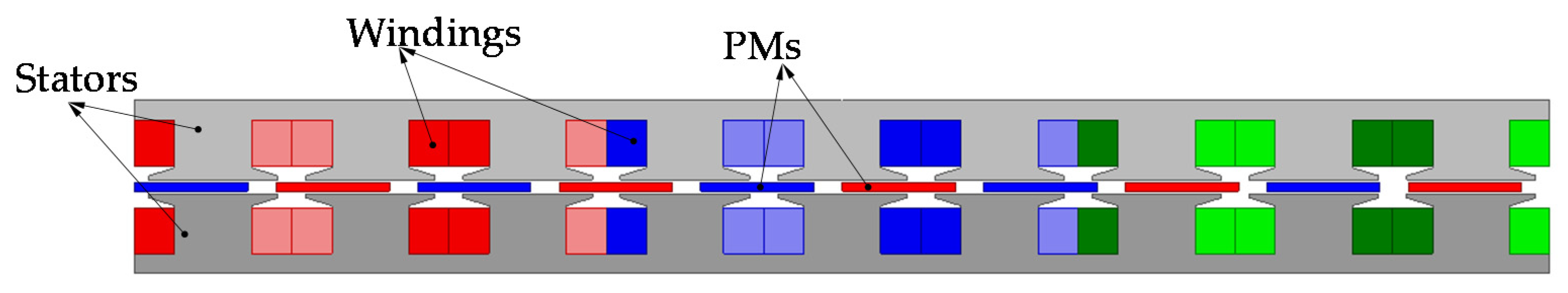
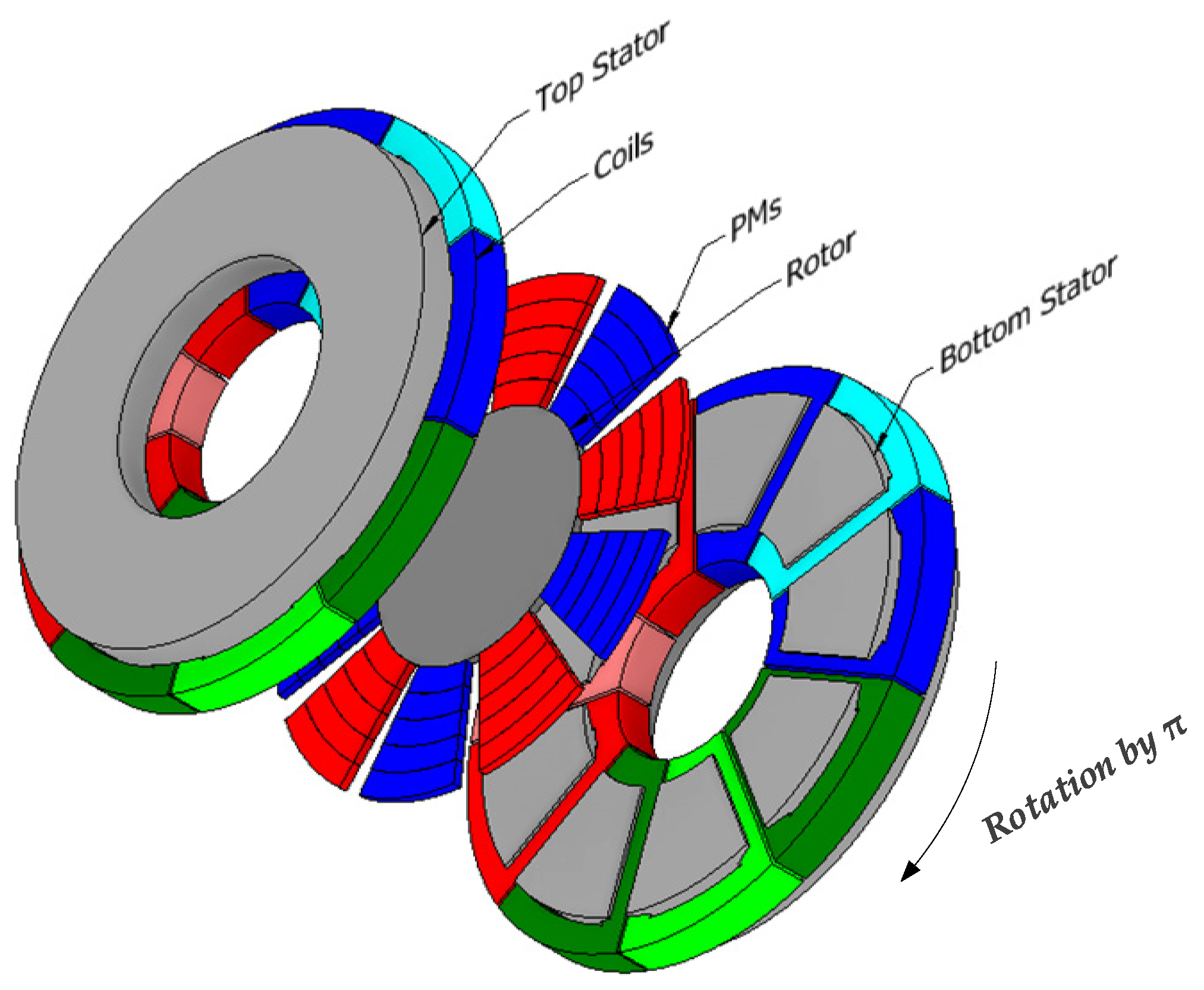
2.1. Motor Topology

A 2D model of a double-sided stator single-rotor (DSSR) AFPM motor is shown in Figure 1. This was developed by cutting the motor to form a cylindrical surface at the mean diameter of the cores and unrolling it to form the planar model [16]. In this paper, the machine is referred to as the conventional double-sided stator single-rotor AFPM motor, where each stator has nine slots with concentrated windings. The 9-slot coil phase sequence is presented in Table 1. This produces the 8-pole and 10-pole dominant magnetic fields travelling in opposite directions [12]. The stator has semi-closed tooth heads, as shown in Figure 1. The rotor has 10 permanent magnets with a non-magnetic supporting structure.
This paper proposes a novel structure, as shown in Figure 2, for the double-sided offset stator single-rotor (DOSSR) AFPM motor, which cancels the 8-pole field. It can be seen that one of the stators is offset by π radians. This harmonic cancellation method has been used in linear machines [13]. The removal of the 8-pole field reduces the PM and core losses considerably since it rotates in the opposite direction of the rotor, which travels in the direction of the 10-pole field.

2.2. Analytical Analysis

Three-phase winding distributions can be represented by positive, negative, and zero sequence components. Normally, when balanced currents are fed into windings, a field going forward is provided by the positive phase sequence (PPS) components and a field going backward is provided by the negative phase sequence (NPS) components while the zero sequence is eliminated [13]. This paper assumes there is a balanced three-phase supply, therefore, the zero sequence component does not need to be considered.

2.2.1. Three-Phase 9-Slot Winding Distribution

The conductor distribution Fourier harmonic expansion is as follows, where n, Np, p, and φp are conductor distribution harmonics, amplitudes of harmonics, harmonic orders, and angular positions, respectively.
n = p = 1 p = N p cos ( p θ + φ p )
The positive sequence components can be derived as follows when p = 1, 4, 7……
n f p = N p 3 [ 1 + ε j ( 2 π p 3 + 2 π 3 ) + ε j ( 2 π p 3 2 π 3 ) ]
The negative sequence components can be given by the following equation when p = 2, 5, 8……
n b p = N p 3 [ 1 + ε j ( 2 π p 3 2 π 3 ) + ε j ( 2 π p 3 + 2 π 3 ) ]
Using the winding factor to represent the amplitude of each harmonic, which is calculated by amplitude divided by the maximum harmonic amplitude.
k w p = | ( 2 cos 2 π p 9 1 ) sin π p 9 |
The detailed derivation can be found in reference [13]. The winding factors for the 9-slot concentrated winding are shown in Table 2. It can be seen that the amplitude of the 4th and 5th components which represent the 8-pole field and 10-pole field, respectively, are dominant. Since it is designed as a 10-pole motor, the 10-pole field produced by the stator winding generates steady torque, whereas the 8-pole field does not contribute to the steady torque production but introduces significant PM eddy current loss and magnetic core loss.

2.2.2. DOSSR AFPM Motor

The offset of the bottom stator and windings by π radians (Figure 2) can effectively cancel the 8-pole magnetic field. As depicted by the arrows in Figure 3a, the field waveforms from the two stator windings reinforce each other for the double-sided stator single-rotor motor. The 8-pole magnetic field is moving forward, whilst the 10-pole is moving backward. By introducing an offset of π radians and reversing the current direction for the bottom stator, it can be seen that the 8-pole magnetic field is eliminated while the 10-pole magnetic field remains the same, as shown in Figure 3b. Table 3 shows the winding factors for the proposed DOSSR AFPM motor, and we again note that the dominant 4th harmonic becomes zero while the dominant 5th harmonic remains the same. In addition, the 2nd and 8th harmonics are eliminated together with the 4th harmonic.

3. 3D Simulation and Result Discussion

3.1. 3D Simulation Model

A 3D double-sided stator single-rotor axial-flux motor model has been built in Ansys Maxwell. The proposed double-sided offset stator single-rotor is simulated by rotating the bottom stator by π radians, as indicated in Figure 4. The key parameters for the axial-flux motor are listed in Table 4. The magnetic core is assumed to be M235-35A, an electrical steel. Neodymium iron boron (NdFeB) N52 permeant magnet is used in the model. Each PM is subdivided into five segments to reduce the eddy current loss [10].

3.2. Base Speed Simulation

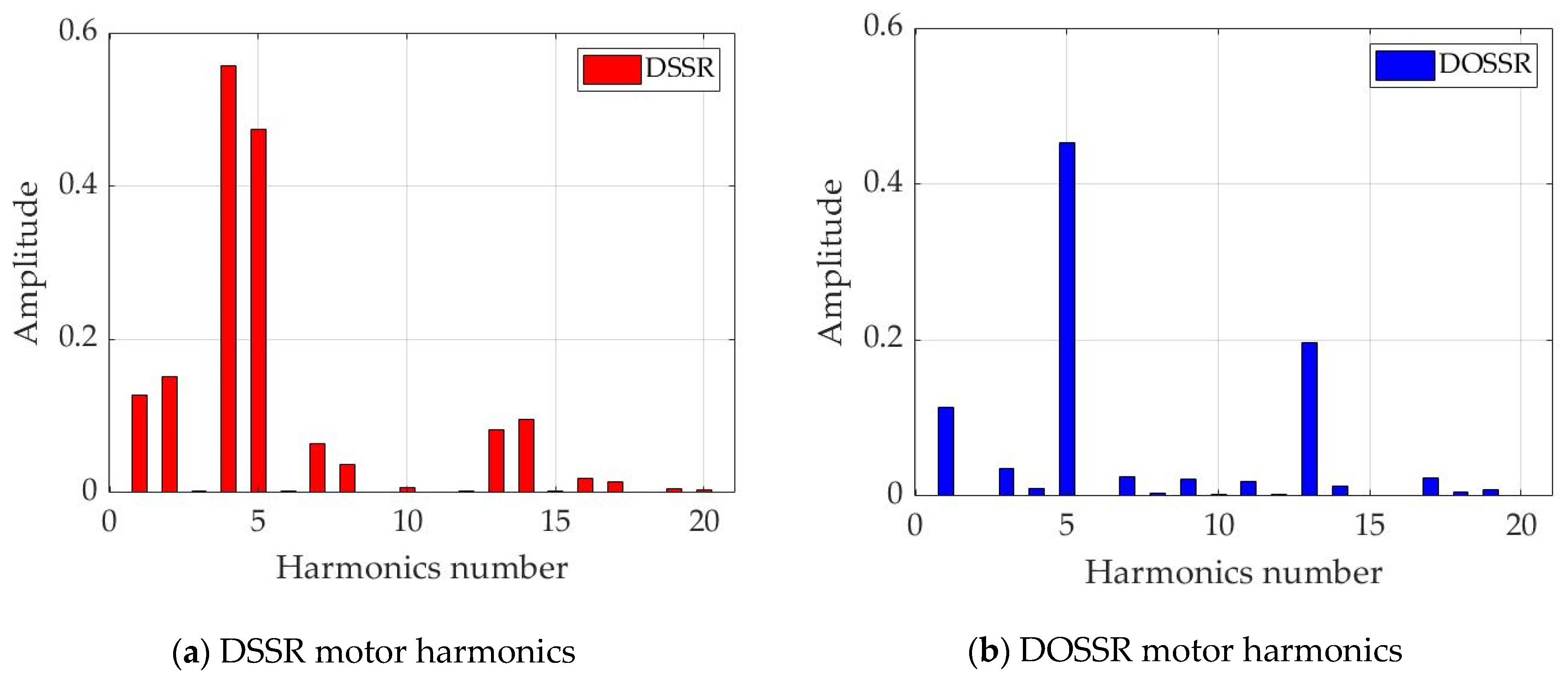
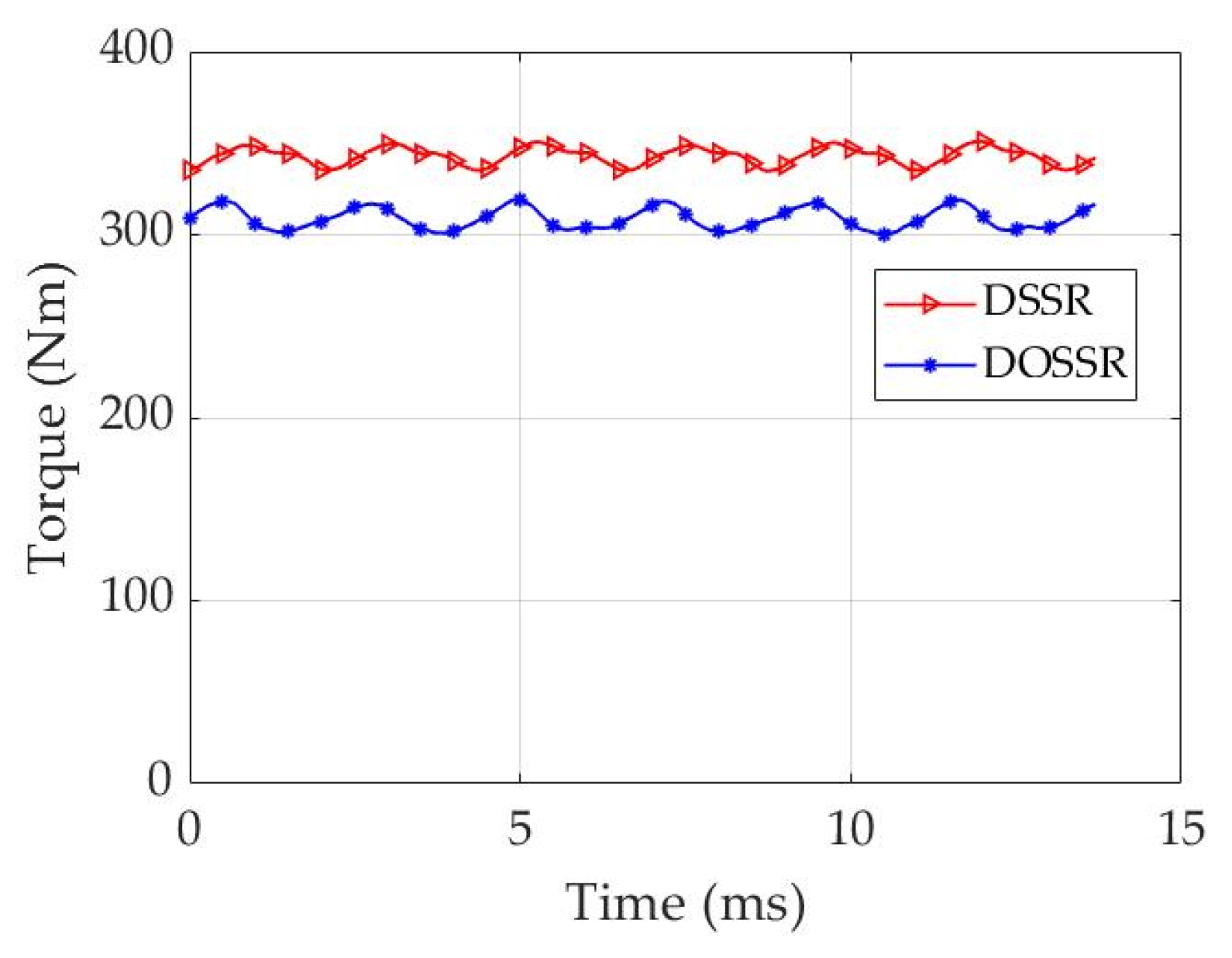
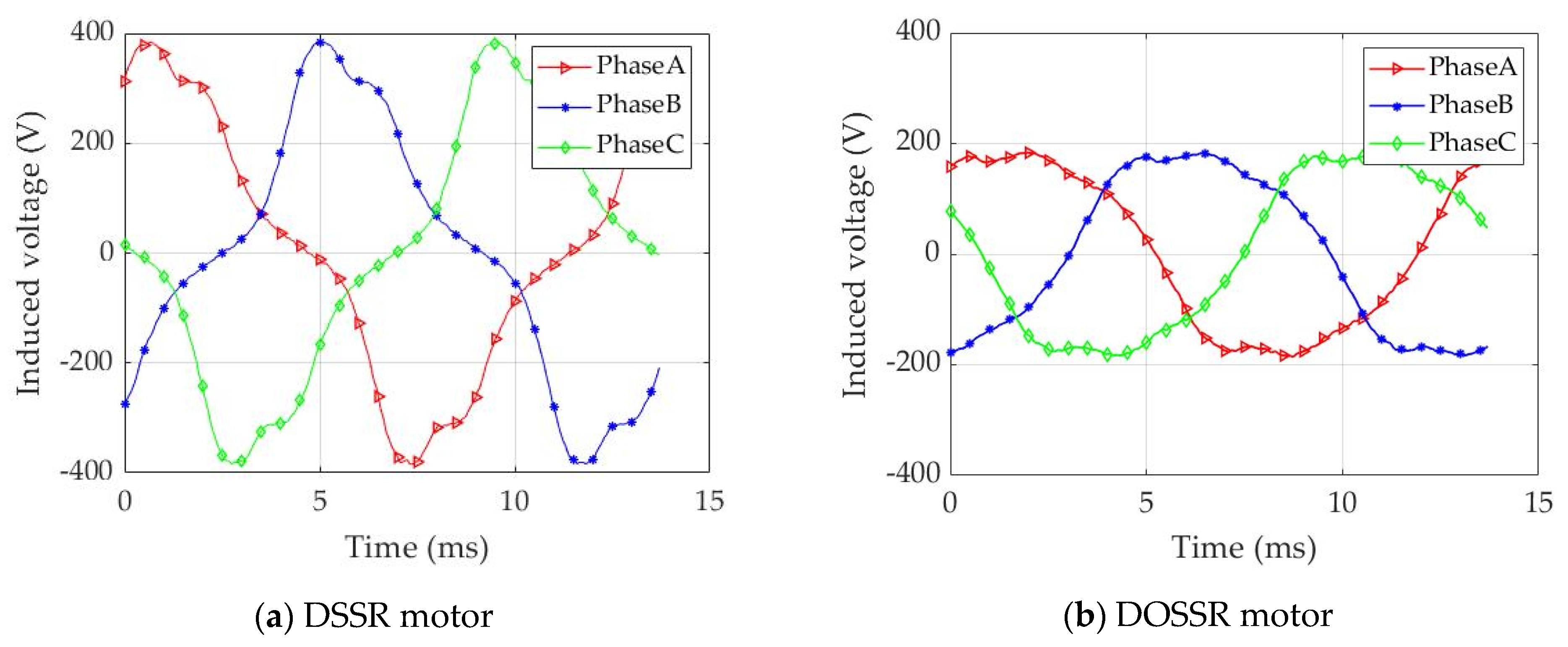
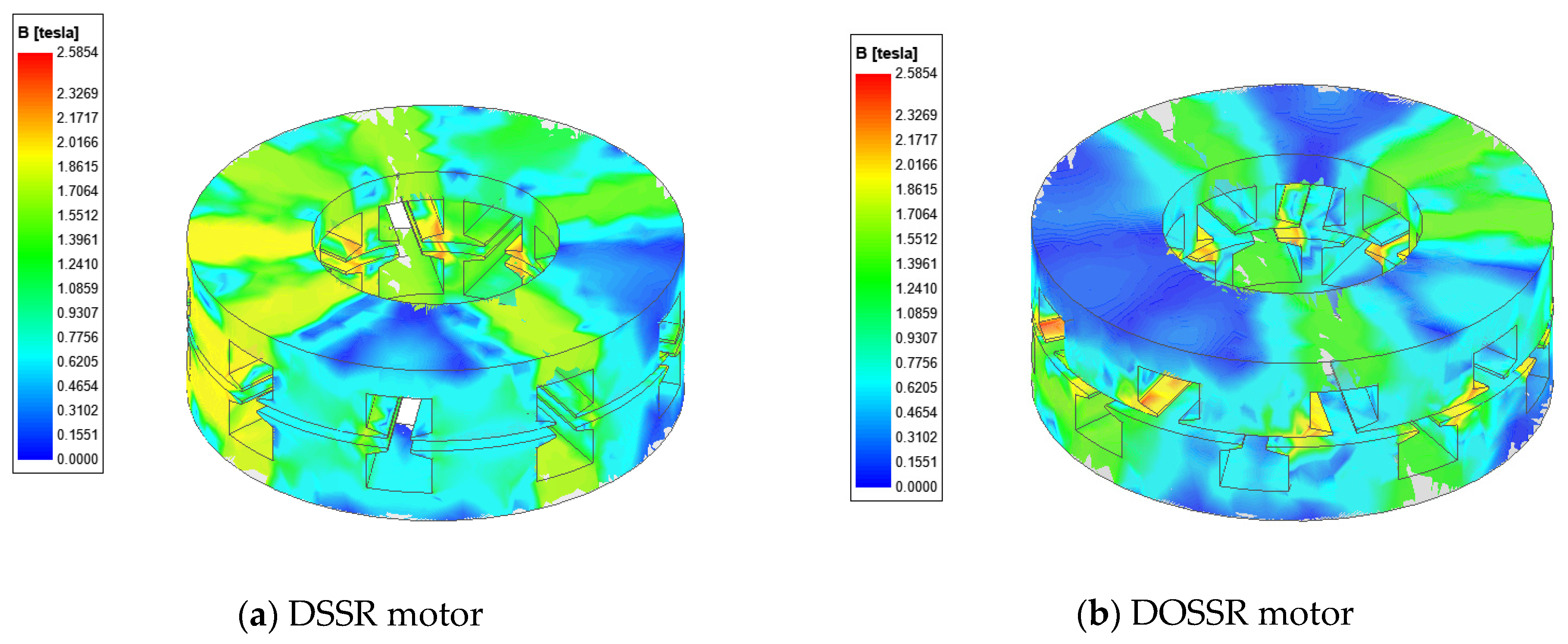
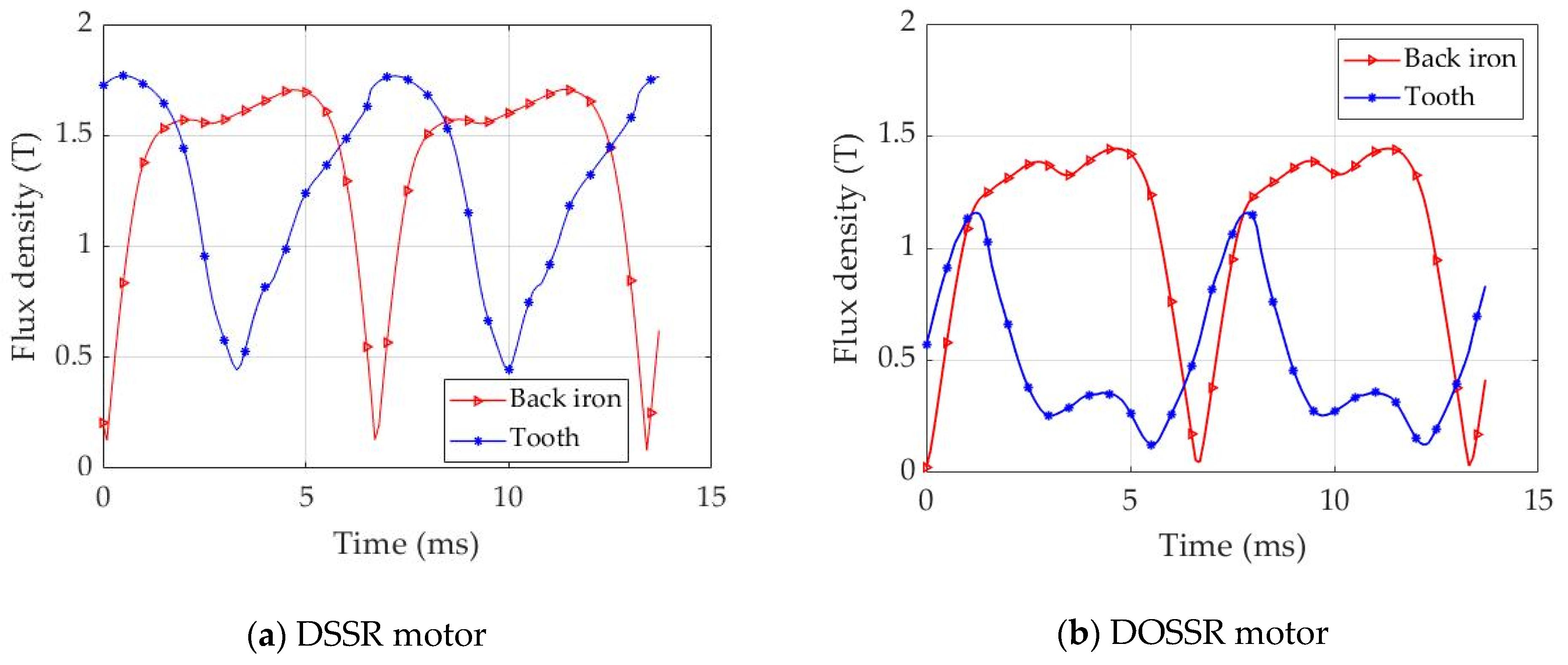
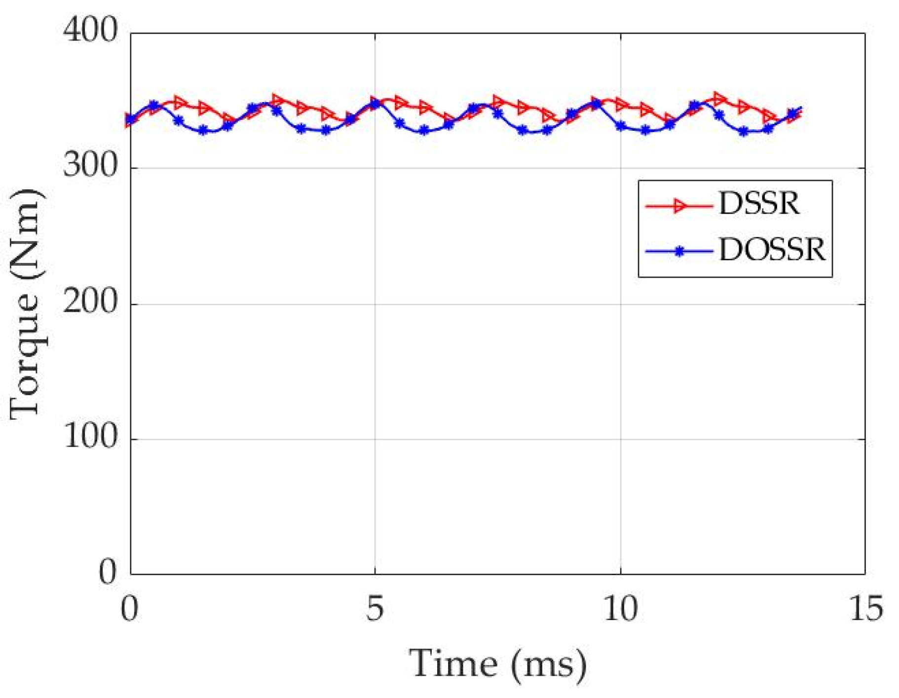
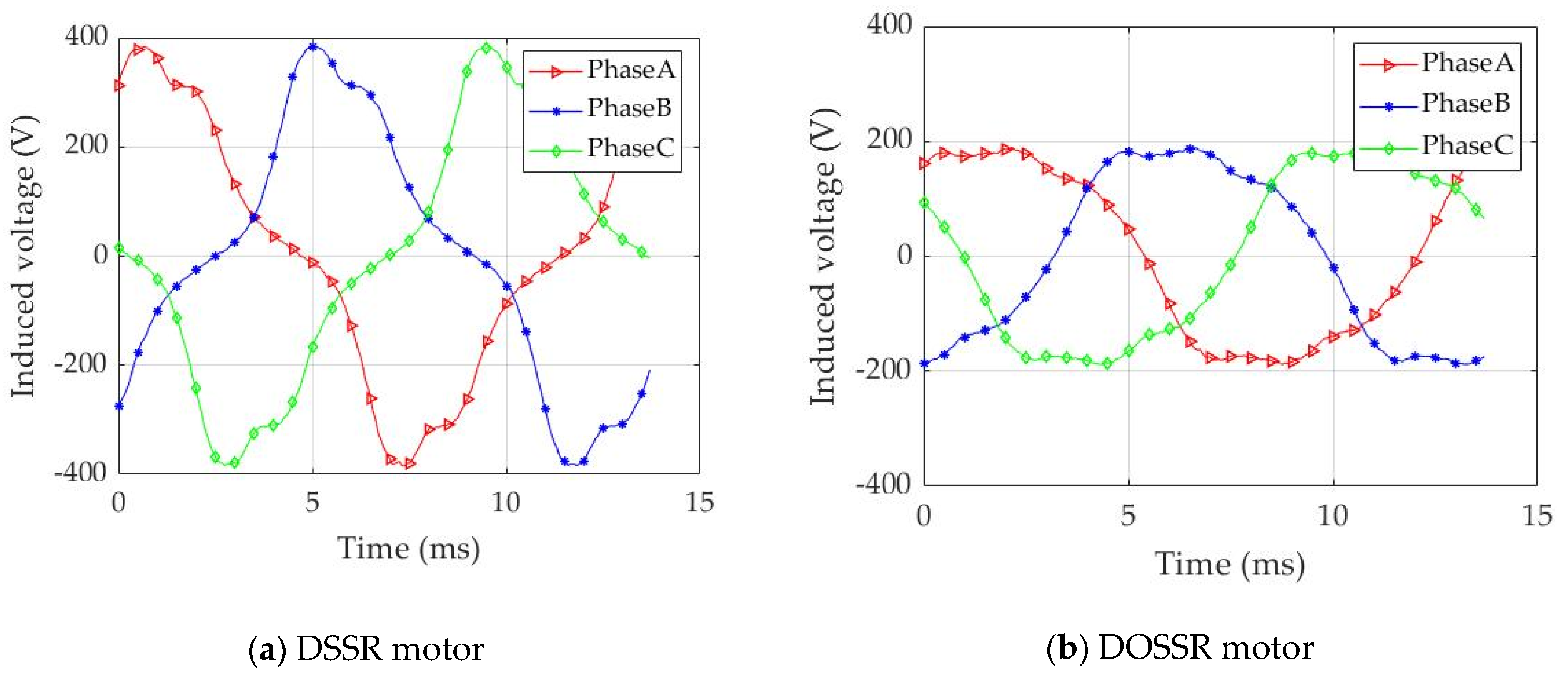
3.2.1. Comparison of the DSSR and the DOSSR Motor with Same Dimensions

The motor base speed (the end of the constant torque region and the beginning of the constant power region) is designed to be 900 rpm, which is the same as the YASA motor described in reference [17]. The stator current is 100 A rms. It is assumed that the current source inverter is used to provide a three-phase pure sinusoidal current. Figure 5 shows the airgap field harmonics FFT with only stator excitation from the 3D FEA model. The 4th harmonic is significantly reduced by offsetting one stator by π radians while the 5th harmonic remains almost the same, which means the 8-pole magnetic field has been eliminated and the 10-pole magnetic field remains almost the same. This validates the analytical analysis in Section 2. The slight reduction in the 10-pole magnetic field for a DOSSR is due to the misalignment of teeth for two stators caused by the offset. Figure 6 shows the magnetic field harmonics FFT with both stator excitation and rotor PMs. The rotor carries magnets to produce a 10-pole field, which causes the 5th harmonic to be higher than the 4th harmonic for DSSR, while the 4th harmonic is effectively eliminated for the DOSSR.
Figure 7 presents the maximum torque produced by the DSSR motor and proposed DOSSR motor for comparison. In the simulation, the model is run for two electrical cycles, and the stable operation in the second cycle is presented in this paper. The outer diameter and axial length of the DSSR motor are close to YASA P400 R [18]. The peak torque for YASA P400 R is 370 Nm and the peak torque for the DSSR is 343 Nm. Therefore, the surface thrust of the DSSR motor is comparable to YASA P400 R. The average torque for the DSSR motor is 343.0 Nm with a torque ripple of 5%. The average torque for the DOSSR motor is 308.7 Nm with a torque ripple of 6.2%. The average torque for the DOSSR motor is 10% lower than the DSSR motor due to the teeth for two stators being misaligned after the offset. This simulation is based on the assumption that the DSSR motor and the DOSSR motor have the same dimensions and parameters for direct comparison. In a practical design, the DOSSR motor can be optimised because the magnetic field in the teeth and back iron is significantly lower than in the DSSR motor.
Figure 8 shows the flux linkage for both DSSR and DOSSR motors. The peak value of the flux linkage induced by the PMs and stator windings is reduced from 0.60 Wb for the DSSR to 0.42 Wb for the DOSSR due to the cancelled 8-pole magnetic field. Therefore, the induced voltage in the stator winding is expected to be reduced as well. As shown in Figure 9, the peak induced voltage is reduced from 384.7 V for the DSSR to 186.3 V for the DOSSR, which is a reduction of 51.6%.
The 3D flux density distribution at the same time for the DSSR and DOSSR motor with 100 A in the stators at 900 rpm is shown in Figure 10. As can be seen, the DOSSR has a reduced magnetic field compared with the DSSR due to the cancellation of the 8-pole magnetic field by the offset stator. The magnitude of the flux density in the back iron and tooth over an electrical cycle is shown in Figure 11. The observation points in the model are located at the back iron and the tooth of the stator. The peak value of the flux density in the back iron is reduced from 1.70 T to 1.44 T, and the peak flux density in the tooth is reduced from 1.77 T to 1.16 T by using the offset stator design. Therefore, the core loss governed by the flux density in the stators is reduced significantly, as shown in Figure 12. The reduction is from 213.1 W to 138.1 W (35.2%), using the offset stator design. Moreover, since the 8-pole field is backward rotating with respect to the rotor, there is a relative motion that introduces eddy current in the PMs. Therefore, the cancellation of the 8-pole magnetic field results in the reduction of the PM eddy current loss by 59.3%, from 252.1 W for the DSSR to 102.7 W for the DOSSR, as shown in Figure 12. This reduction in PM losses is especially pertinent, since controlling rotor temperatures is a particular challenge for electric machines due to the difficulty involved in cooling the rotor.

3.2.2. DOSSR Motor Redesign

As mentioned in the last section, the DOSSR motor has the same dimension as the DSSR motor, and the torque for the DOSSR is 10% lower due to the misalignment of the teeth for the two stators. Therefore, the DOSSR can be redesigned and optimised, as there is an adequate margin before the saturation of the core, as shown in Figure 11b. A simple redesign is applied in which the thickness of the PM is increased from 4.5 mm to 5 mm for the DOSSR to deliver the same torque as the DSSR motor.
Figure 13 shows the torque for the DSSR motor with a PM thickness of 4.5 mm and the DOSSR motor with a PM thickness of 5 mm. The torque for the DOSSR is increased to 335 Nm, which is only 2.3% lower than the DSSR motor. Due to the increase of the PM thickness, the maximum flux linkage has witnessed a tiny increment from 0.42 T to 0.43 T, as shown in Figure 14 which, as a result, increases the induced voltage from 186.3 V to 187.6 V for the DOSSR. However, the reductions of an induced voltage are still remarkable compared with the DSSR from 384.7 V to 187.6 V as shown in Figure 15. This means that the proposed DOSSR motor can use a much lower battery and DC bus voltage to deliver the same power. The power factor for the proposed DOSSR motor is much higher than the DSSR motor.
Figure 16 shows the flux density in the back iron and tooth. The flux density in the DOSSR motor with a PM thickness of 5 mm is still significantly lower than the DSSR motor with a PM thickness of 4.5 mm, which means that the DOSSR could be further optimised. Figure 17 presents the core loss and PM loss comparison, where the core loss is reduced from 213.1 W for the DSSR motor to 148.5 W for the DOSSR motor, which is a reduction of 30.3% with a PM thickness of 5 mm. The PM loss is reduced from 252.1 W for the DSSR motor to 119.2 W for the DOSSR motor (reduction of 52.7%) with a PM thickness of 5 mm.

3.3. Discussion

Table 5 summarises the losses and efficiencies for the DSSR motor, the DOSSR motor, and the DOSSR motor with a PM thickness of 5 mm at the base speed of 900 rpm. The proposed DOSSR motor reduces the core and PM losses by 48.2% at the base speed by simply rotating one of the stators by π radians. With the redesign of the thickness of PMs for the DOSSR, the torque is compensated and, therefore, the output power is similar to the DSSR while providing higher efficiency. From the simulation results, the proposed offset stator motor has the following advantages compared with the conventional DSSR motor: Firstly, the induced voltage is significantly reduced for the same power rating. This means that the DC bus voltage can be reduced and therefore the battery voltage can be reduced. Alternatively, the same motor could be run to a much higher power if the field’s weakening region is pushed to a higher speed. Secondly, the flux density in the magnetic core is much lower, which can reduce the magnetic core losses. On the other hand, the thickness of permeant magnets can be increased to increase the power rating of the offset stator motor with the same physical size. Thirdly, the 8-pole magnetic field is eliminated, which leads to more than a halving of the permeant magnet eddy current loss. This reduces the requirement for the rotor cooling system, which is a considerable benefit. The only disadvantage of the offset stator motor is that the torque is slightly lower than the DDSR with the same dimension because of the misalignment of the tooth for stators. However, this can be improved by the motor redesigning through winding and permeant magnet optimisation.

4. Conclusions

This paper proposes a novel double-sided offset stator single-rotor axial-flux motor, which can effectively eliminate the 8-pole magnetic field produced by a 9-slot concentrated winding, without affecting the 10-pole magnetic field. The baseline DSSR AFPM motor is compared with the proposed DOSSR AFPM motor using analytical analysis and a finite element simulation. The results show that the proposed DOSSR has a significantly lower core loss and permeant magnet loss and can be driven by the lower battery voltage. This proposed double-sided offset stator axial-flux motor has a great potential to be used as a high-efficiency direct-drive electric vehicle motor. An optimised DOSSR AFPM motor will be designed for traction in an EV. A prototype DOSSR AFPM motor will be built and experimentally tested to validate the results.

Author Contributions

Conceptualization, X.P. and J.F.E.; methodology, H.W., X.P. and J.F.E.; software, H.W. and B.Y.; validation, H.W., X.P. and X.Z.; formal analysis, H.W., X.P. and J.F.E.; investigation, H.W., X.P. and J.F.E.; data curation, H.W. and X.P.; writing—original draft preparation, H.W. and X.P.; writing—review and editing, J.F.E., C.V. and X.Z.; supervision, X.P. and X.Z.; All authors have read and agreed to the published version of the manuscript.

Funding

This research received no external funding.

Institutional Review Board Statement

Not applicable.

Informed Consent Statement

Not applicable.

Data Availability Statement

The data presented in this study are available on request from the corresponding author.

Conflicts of Interest

The authors declare no conflict of interest.

References

  1. Mahmoudi, A.; Kahourzade, S.; Rahim, N.A.; Ping, H.W.; Uddin, M.N. Design and prototyping of an optimised axial-flux permanent-magnet synchronous machine. IET Electr. Power Appl. 2013, 7, 338–349. [Google Scholar] [CrossRef]
  2. Chan, C. Axial-field electrical machines-design and applications. IEEE Trans. Energy Convers. 1987, EC-2, 294–300. [Google Scholar] [CrossRef]
  3. Taran, N.; Klink, D.; Heins, G.; Rallabandi, V.; Patterson, D.; Ionel, D.M. A Comparative study of yokeless and segmented armature versus single sided axial flux pm machine topologies for electric traction. IEEE Trans. Ind. Appl. 2022, 58, 325–335. [Google Scholar] [CrossRef]
  4. Lombard, N.; Kamper, M. Analysis and performance of an ironless stator axial flux PM machine. IEEE Trans. Energy Convers. 1999, 14, 1051–1056. [Google Scholar] [CrossRef]
  5. Aydin, M.; Huang, S.; Lipo, T.A. Axial flux permanent magnet disc machines: A review. Conf. Rec. SPEEDAM 2004, 8, 61–71. [Google Scholar]
  6. Eastham, J.; Profumo, F.; Tenconi, A.; Hill-Cottingham, R.; Coles, P.; Gianolio, G. Novel axial flux machine for aircraft drive: Design and modeling. IEEE Trans. Magn. 2002, 38, 3003–3005. [Google Scholar] [CrossRef]
  7. Kowal, D.; Sergeant, P.; Dupre, L.; Bossche, A.V.D. Comparison of nonoriented and grain-oriented material in an axial flux permanent-magnet machine. IEEE Trans. Magn. 2010, 46, 279–285. [Google Scholar] [CrossRef]
  8. Rahman, K.M.; Patel, N.J.; Ward, T.; Nagashima, J.; Caricchi, F.; Crescimbini, F. Application of direct-drive wheel motor for fuel cell electric and hybrid electric vehicle propulsion system. IEEE Trans. Ind. Appl. 2006, 42, 1185–1192. [Google Scholar] [CrossRef]
  9. Marignetti, F.; Colli, V.D.; Carbone, S. Comparison of axial flux pm synchronous machines with different rotor back cores. IEEE Trans. Magn. 2010, 46, 598–601. [Google Scholar] [CrossRef]
  10. Li, T.; Zhang, Y.; Liang, Y.; Yang, Y.; Jiao, J. Magnet eddy-current losses reduction of an axial-flux in-wheel motor with amorphous magnet metal. Int. J. Appl. Electromagn. Mech. 2021, 65, 431–450. [Google Scholar] [CrossRef]
  11. Eastham, J.F.; Cox, T.; Lai, H.C.; Proverbs, J. The use of concentrated windings for offset double stator linear induction motors. Electromotion 2008, 2, 51–56. [Google Scholar]
  12. Eastham, F. Transient analysis of offset stator double sided short rotor linear induction motor accelerator. In Proceedings of the 20th International Conference on Magnetically Levitated Systems and Linear Drives (MAGLEV 2008), San Diego, CA, USA, 15–18 December 2008. [Google Scholar]
  13. Eastham, J.; Cox, T.; Proverbs, J. Application of planar modular windings to linear induction motors by harmonic cancellation. IET Electr. Power Appl. 2010, 4, 140–148. [Google Scholar] [CrossRef]
  14. Kremer, M. Electromagnetic Design of a Disc Rotor Electric Machine As Integrated Motor-Generator for Hybrid Vehicles. Ph.D. Thesis, Université de Haute Alsace-Mulhouse, Mulhouse, France, 2016. [Google Scholar]
  15. Di Gerlando, A.; Foglia, G.M.; Iacchetti, M.F.; Perini, R. Axial flux PM machines with concentrated armature windings: Design analysis and test validation of wind energy generators. IEEE Trans. Ind. Electron. 2011, 58, 3795–3805. [Google Scholar] [CrossRef]
  16. Gair, S.; Canova, A.; Eastham, J.; Betzer, T. A new 2D FEM analysis of a disc machine with offset rotor. In Proceedings of the International Conference on Power Electronics, Drives and Energy Systems for Industrial Growth, New Delhi, India, 8–11 January 1996; Volume 1, pp. 617–621. [Google Scholar]
  17. Di Gerlando, A.; Foglia, G.; Ricca, C. Analytical design of a high torque density In-Wheel YASA AFPM motor. In Proceedings of the 2020 International Conference on Electrical Machines (ICEM), Gothenburg, Sweden, 23–26 August 2020; Volume 1, pp. 402–408. [Google Scholar]
  18. YASA P400|Compact Electric Vehicle Motor|YASA Ltd. Available online: https://www.yasa.com/products/yasa-p400/ (accessed on 8 March 2022).
Figure 1. Double-sided stator single-rotor (DSSR) AFPM motor in 2D.
Wevj 13 00052 g001
Figure 2. Proposed double-sided offset stator single-rotor (DOSSR) AFPM motor in 2D.
Wevj 13 00052 g002
Figure 3. 8-pole and 10-pole magnetic fields.
Wevj 13 00052 g003
Figure 4. 3D model of the DSSR AFPM motor.
Wevj 13 00052 g004
Figure 5. Airgap magnetic field harmonics FFT with only stator excitation for the DSSR motor and the DOSSR motor.
Wevj 13 00052 g005
Figure 6. Airgap magnetic field harmonics FFT with stator excitation and rotor PMs for the DSSR motor and the DOSSR motor (100 A rms, 900 rpm).
Wevj 13 00052 g006
Figure 7. Torque for the DSSR motor and the DOSSR motor (100 A rms, 900 rpm).
Wevj 13 00052 g007
Figure 8. Flux linkage for the DSSR motor and the DOSSR motor (100 A rms, 900 rpm).
Wevj 13 00052 g008
Figure 9. Induced voltage for the DSSR motor and the DOSSR motor (100 A rms, 900 rpm).
Wevj 13 00052 g009
Figure 10. Flux density distribution for the DSSR motor and the DOSSR motor (100 A rms, 900 rpm).
Wevj 13 00052 g010
Figure 11. Flux density for the DSSR motor and the DOSSR motor (100 A rms, 900 rpm).
Wevj 13 00052 g011
Figure 12. Comparison of core loss and PM loss for the DSSR motor and the DOSSR motor operating at peak torque at base speed (100 A rms, 900 rpm).
Wevj 13 00052 g012
Figure 13. Torque for the DSSR motor with PM thickness of 4.5 mm and the DOSSR motor with PM thickness of 5 mm.
Wevj 13 00052 g013
Figure 14. Flux linkage for the DSSR motor with PM thickness of 4.5 mm and the DOSSR motor with PM thickness of 5 mm.
Wevj 13 00052 g014
Figure 15. Induced voltage for the DSSR motor with PM thickness of 4.5 mm and the DOSSR motor with PM thickness of 5 mm.
Wevj 13 00052 g015
Figure 16. Flux density for the DSSR motor with PM thickness of 4.5 mm and the DOSSR motor with PM thickness of 5 mm.
Wevj 13 00052 g016
Figure 17. Comparison of core loss and PM loss for the DSSR motor with PM thickness of 4.5 mm and the DOSSR motor with PM thickness of 5 mm operating at peak torque at base speed (100 A rms, 900 rpm).
Wevj 13 00052 g017
Table 1. 9-slot 8/10-pole concentrated winding connection.
Coil Number123456789
Coil phasea−aab−bbc−cc
Table 2. Winding factors of the DSSR motor.
Pole Pairs123456789101112
PPS0.061000.945000.139000.06100
NPS00.139000.945000.061000.1390
Table 3. Winding factors of DOSSR AFPM motor.
Pole Pairs123456789101112
PPS0.061000000.13900000
NPS00000.945000000.1390
Table 4. Specification of the DSSR AFPM motor.
ParameterValue
Pole-pair number5
Stator outer diameter300 mm
Stator inner diameter150 mm
Motor axial length87 mm
Back iron thickness20 mm
Tooth height23 mm
Tooth head height7 mm
Slot number9
Slot width40 mm
Rotor outer diameter300 mm
Rotor core diameter150 mm
Air gap1.25 mm
Permanent magnet thickness4.5 mm
Permanent magnet angle28.8°
Table 5. Losses and efficiency for the DSSR motor and the DOSSR motor at base speed.
ItemDSSRDOSSRDOSSR Redesign
Torque (Nm)343.0308.7335.0
Power rating (kW)32.329.131.57
Core loss (W)213.1138.1148.5
PM loss (W)252.1102.7119.2
Copper loss (W)917.9 917.7917.7
Efficiency (%)95.496.096.2
Publisher’s Note: MDPI stays neutral with regard to jurisdictional claims in published maps and institutional affiliations.

