Review

Potentials of Brushless Stator-Mounted Machines in Electric Vehicle Drives—A Literature Review

1
Department of Electrical Engineering, Tshwane University of Technology, Pretoria 0183, South Africa
2
Department of Electrical Engineering, University of Nigeria, Nsukka 410001, Nigeria
3
Department of Electrical and Electronic Engineering, Stellenbosch University, Stellenbosch 7600, South Africa
4
Centre for Energy & Electric Power (CEEP), Department of Electrical Engineering, Tshwane University of Technology, Pretoria 0183, South Africa
*
Authors to whom correspondence should be addressed.
World Electr. Veh. J. 2022, 13(5), 93; https://doi.org/10.3390/wevj13050093
Submission received: 31 March 2022 / Revised: 30 April 2022 / Accepted: 17 May 2022 / Published: 20 May 2022

Abstract

:
Brushless stator-mounted traction motors, which are new and emerging, have many potential applications in the electrified transport industry. Brushless stator-mounted machines (BSSMs), with the so-called flux modulation (FM) effects, use asynchronous field harmonics to realize energy conversion by altering the basic principle for conventional machine design which requires the stator and rotor to have the same pole number. The machines show promise of meeting the challenging requirements of electric vehicle (EV) traction motors. Therefore, in this paper, a review is undertaken on the state-of-the-art and potentials of the BSSMs for EV drives. The focus on BSSMs is due to their suitability for high-speed high torque density performance, as well as possessing suitable heat dissipation and flux weakening capabilities. The study is used to first rehash and discuss the design and excitation topologies, operating principles, and some emerging trends based on the basic BSSM variants, e.g., the doubly salient machine, flux reversal machine, and flux switching machine, while also undertaking a bibliometric synthesis on relevant studies highlighting the design and performance candidature of these niche BSSMs in EV applications, especially when compared to the well-developed Prius–IPM motor.

1. Introduction

With an estimated increase in oil-powered passenger vehicles (1.5 billion cars on the road projected by 2050 [1]), considering that oil itself is a finite resource and that the demand for it will increase proportionately, it is therefore commonsense for strategic plans that focus on alternative future transportation methods. Electric vehicles (EVs), or electric traction drives, employ processed electricity rather than crude oil as the powering fuel. In recent times, the EV market has grown significantly [2,3,4,5]. Certain benefits accruing from the ongoing transition in the transport industry include the reduction of greenhouse gas (GHG) emissions, the promotion of renewable and sustainable energy generation, improved quality of life, opportunities for new investments, and the large-scale creation of jobs, among others.
The transportation sector contributes about 41% of worldwide greenhouse emissions [6]. No doubt, the electrification of transportation sector is capable of reducing this environmental pollution problem in an effective way through the use of more efficient electrified powertrains. Hence, researchers are more focused on developing alternative, sustainable, and emission-free transportation systems [7,8,9].
The traction motor is an integral part of EV powertrains and plays a significant role in their design architecture. Depending on the application, the selection of a traction motor involves many considerations, such as simple construction, ruggedness, being lightweight, volume, cost, efficiency, torque density, the ease and flexibility of the electric drive control, fault tolerance and harshness capability, a fast and quick torque response especially at starting, a wide constant power speed range (CPSR), low acoustic noise (torque ripple), low rotor inertia, regenerative braking and overload capability, good temperature management, as well as high operational reliability on different driving conditions [2,5,10,11,12]. Among these various requirements, an excellent flux weakening defined by a wide CPSR capability curve, as shown in Figure 1, is often required in EV operational performance.
Traditionally, DC motors [13,14], induction motors (IMs) [15,16,17,18], permanent magnet synchronous motors (PMSMs) [19,20,21,22], wound rotor synchronous machines (WRSMs) [23,24], hybrid synchronous motors (HSM) [25], and switch reluctance motors (SRMs) [26,27], are the most popular traction motors. Each of these traction motor types has its own unique advantages and disadvantages in terms of cost, efficiency, power density, and manufacturability [2,28]. Table 1 provides a summary on the industrial uptake of traditional EV motors, while Table 2 shows their performance characterization [9,29,30,31] based on a simple five-point rating system, where point one represents the lowest and point five represents the highest grade. Based on the overall score in Table 2, IMs and PMSMs are seen as the preferred EV motors due to their better performance and operational characteristics. However, based on a thorough characterization provided in [2], no preference is given on the highlighted motors since each display noteworthy strengths and comparative weaknesses.
Although IMs and PMSMs are widely used in EV powertrains, the search for more competitive traction motors remains an evolving task. To this end, the development of new types of electric traction motors that operate on the flux modulation (FM) principle are emerging [32,33,34,35,36,37,38]. These machines include the magnetically geared machines [39,40,41,42], Vernier machines [43,44], and stator-mounted PM and wound field machines [45,46,47,48], to mention a few. Unlike classical electrical machines, FM machines achieve energy conversion by using asynchronous field harmonics. Stator-mounted PM and wound field machines feature rugged and simple rotors and are suitable for high-speed or high-torque applications. Like classical synchronous machines, they can be easily adapted to PM, non-PM, and even hybrid-excited topologies. However, stator-mounted PM and wound field machines are characteristically prone to high-cogging torque and torque ripple due to their double-salient features [49], which is a matter of concern in EV applications. The candidature of stator-mounted PM and wound field machines for EV drives is due to their excellent flux weakening and CPSR capabilities [50,51,52].
In this paper, an overview will be presented on the trending brushless stator mounted machines (BSMMs) as it relates to their development for traction motor drives. In previous bibliographical niche studies [4,5,10,25,30,31,32,37], such an emphasis, as it relates to FM motors in EV applications, has only been at least inferred but never conceptualized. In [39], the authors focused on the motor designs with reduced rare-earth material, which still limits the scope, while in [48] the study only focuses on FSPM motors. It is also important to clarify that while the study in [45] also covers the three variants of BSMMs considered in this study, their study emphasized BSMM topologies with PM excitation, and there was no emphasis placed on EV drivetrains. This current study collects the potential of FM electrical motors in EV drives in terms of their design, analysis, and performance evaluation, with the hope that in the next decade one of these FM motors will make it to the industrial hall of fame summarized in Table 1. The rest of the paper will be organized as follows: Section 2 is used to rehearse the variants and main excitation categories of the BSMMs, highlighting machine operating principle and critical EV performance metrics such as torque and flux weakening capabilities. Then, Section 3 provides a qualitative and quantitative comparison of the highlighted BSMMs in terms of emerging design trends and performance evaluation studies focused on the design of EV traction motors based on PM, wound field, and hybrid-excited FM machines. Lastly, relevant conclusions are drawn in Section 4.

2. Brushless Stator Mounted Machines

These are brushless machines that have their excitation sources located in the stator. Among different types of flux modulation (FM) machines, BSMMs are of great interest in EV application due to their definite advantages in having a robust structure, high power density, and high efficiency. In the case of rotor-PM machines, they usually need to be protected from the centrifugal forces by employing retaining sleeves while a higher risk of irreversible demagnetization results due to poor thermal dissipation of PMs placed in the rotor. Also, in rotor wound field machines, field flux is mostly difficult without the use of slip rings and brushes. In contrast, BSMMs have PMs or DC electromagnets on the stator which help to alleviate the problems suffered by their rotor-mounted counterparts. As a result, BSMMs are suitable for high-speed or high-torque designs. Based on the location of excitation sources in the stator, there are three types of BSMMs: doubly salient BSMMs [53], in which the excitation sources originate from the stator yoke; flux reversal BSMMs [54], in which the excitation sources originate from the stator tooth tips; and flux switching BSMMs [55], in which excitation sources originate from the stator teeth sides. A broad classification of the different BSMMs based on excitation modes is shown in Figure 2. The following subsections will discuss this classification in terms of operating principles, torque, and field weakening capabilities.

2.1. Doubly Salient BSMMs

Doubly salient BSMMs can be excited using only PM (DSPMM), DC wound field (DSWFM), or a hybrid combination of PM and DC wound field (DSHEM). In this sub-section, the basic principle of operation is first highlighted based on the different excitation topologies, and thereafter a synthesis of the doubly salient BSMMs—in terms of analysis of important EV performance metrics such as torque and flux weakening capability—are undertaken.

2.1.1. Doubly Salient PM Machine (DSPMM)

The basic topology of a three-phase 6-stator-pole/4-rotor-tooth (6/4-pole) DSPMM machine is shown in Figure 3a [45]. It has six slots in the stator, four salient poles in the rotor, and two pieces of circumferentially magnetized PMs inserted in the stator yoke.

Operating Principles

DSPMM has a small phase winding inductance due to positions of PMs. As the rotor rotate, the flux linkages of these PMs vary. It is this variation of flux that is responsible for back EMF in the stator winding. A non-load plot of flux linkage against rotor position is shown in Figure 3b [45,53]. The shape of the back-EMF is trapezoidal. Thus, brushless DC (BLDC) operation can be adopted. Also, a unidirectional torque is possible by introducing positive and negative current in the winding at the rising and falling of flux linkage, respectively.

Torque Ripple Minimization

Due to presence of salient poles in both the stator and rotor, DSPMMs suffer high-torque ripple [53,56]. The torque ripple greatly affects their performance in EV applications by producing motor acoustics and vibrations. Three categories of torque ripples can be described in DSPMM machines [56]:
  • First, torque ripple due to double-salient geometry under ideal operating conditions. This torque ripple is expected in any machine with such a topology and is called operating torque ripple.
  • Second, torque ripple due to operating conditions of the machine such as magnetic saturation, the nature of stator current, and the fringing effect. This torque ripple is dependent on the operating condition and is called practical torque ripple.
  • Third, torque ripple introduced due to imperfections in the factory production of the machine. Some of the production imperfections that introduce this torque ripple are machine asymmetry and the eccentricity of some rotating parts. This torque ripple is called manufacturing torque ripple.
To minimize torque ripples and improve the performance of DSPMMs, several studies have been carried out, many of which focus on either the design method [57,58,59] or control method [60,61,62]. While the proper sizing of PMs in DSPMM eliminates vibrations and ensures stability [57], a proper winding configuration minimizes toque ripple [58]. In [59], the performance characteristics of DSPMMs with different stator iron core segments were compared. It was shown that π c o r e exhibits the best torque capability and smallest torque ripple.
For the control method, a tremendous reduction in torque ripple factor, from 81% to 21%, were seen in [60] by optimizing the conduction angle of DSPMM using a genetic algorithm. In [61], a new harmonic current method was proposed to minimize the torque ripple of a DSPMM, while in [62], a remedial brushless ac (BLAC) operation was proposed and implemented for fault tolerant DSPMM drives. It was shown that BLAC operation can maintain an average torque and reduce torque ripple while retaining self-starting capability under an open-circuit fault.

Field Weakening Capability and Efficiency

DSPMMs have the advantages of high-power density and high efficiency, but a very difficult to control the flux since the main airgap flux comes from PMs. Therefore, the field weakening is very poor, thereby making DSPMMs suffer from a limited CPSR of about two units [53]. This is a very serious concern in EV application.

2.1.2. Doubly Salient Wound Field Machine (DSWFM)

To solve the concerns of a limited field airgap flux control and a high cost posed by the DSPMM, a new configuration called the doubly salient wound field motor (DSWFM) was introduced [63]. In this new configuration, PMs in the DSPMM were replaced with field windings, as shown in Figure 4a.

Operating Principles

Just like in DSPMMs under no-load conditions, a trapezoidal back-EMF is obtained in the stator winding as the rotor rotates. This necessitates BLDC operation in DSWFM, and like in DSPMMs, unidirectional torque is also possible. A plot of flux variations is shown in Figure 4b.

Torque Ripple Minimization

Unlike DSPMMs where the torque ripple could be as high as 81% [56], a DSWFM could yield a torque ripple as low as 6% [63]. The low torque ripple is because the phase current amplitude is always kept at a constant and in synchronism with the back-EMF.

Field Weakening Capability and Efficiency

With the DSWFM configuration, flux control is possible as demonstrated in [63]. By adjusting the field current, DSWFMs can provide constant torque when the motor is running at below the rated speed and maintaining a constant power above twice the rated speed. It also yields an efficiency of about 73% near the rated load and below 65% at a light load. Poor efficiency is due to the addition of copper losses from field windings, which limits the application of DSWFM in EV drives.

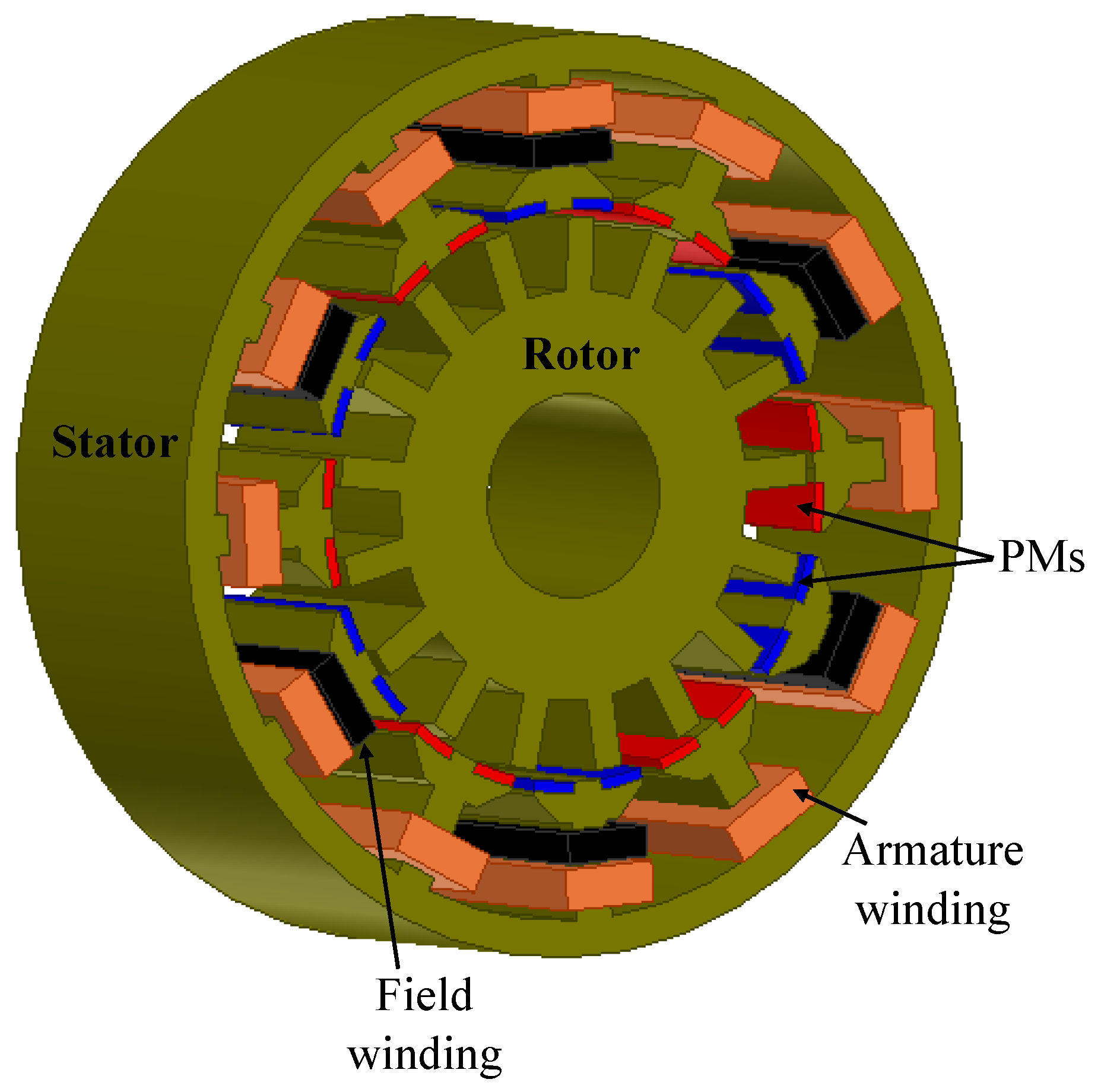
2.1.3. Doubly Salient Hybrid-Excited Machine (DSHEM)

Since DSPMMs and DSWFMs are limited in EV applications due to their poor field weakening and low efficiency, respectively, both machines were merged to form a new configuration called the doubly salient hybrid-excited machine (DSHEM) [64], where the excitation sources are from PMs and DC electromagnets, as shown in Figure 5.

Operating Principles

The PM torque and reluctance torque are two torques produced in DSHEM due to PMs and the double salient geometry of the machine [64]. PM torque is the most desirable and should be maximized using the appropriate control of the flux linkage variation.

Torque Ripple Minimization

At normal operating speeds, reluctance torque is the main source of torque ripple in DSHEMs, and it should be made as small as possible to have a smoother toque. This is possible by choosing magnitude and wave shape of inductances at the design stage to produce a special self-inductance wave shape that will cancel reluctant torque resulting from variations of self-inductance and ensure less torque ripple. By adjusting the field current, inductances can also be controlled to reduce torque ripple [64].

Field Weakening Capability

Reference [64] shows that the hybrid-excitation design of the doubly salient BSMM can achieve a field weakening of 100% and a high-torque density without compromising its performance. The superior torque capability (up to 2 p.u.) of the DSHEM makes it a very good candidate for EV applications.

2.2. Flux Reversal BSMM

The excitation source in the flux reversal BSMM can either be PMs viz., a flux reversal PM machine (FRPMM), DC wound field (FRWFM), or hybrid-excited (FRHEM).

2.2.1. Flux Reversal PM Machine (FRPMM)

FRPMM have the advantages of a robust rotor structure and stator-mounted excitation configuration for easy heat management, making them very promising for both low-speed and high-speed applications [54]. The basic topology of the FRPMM is shown in Figure 6a.

Operating Principles

FRPMMs have tooth concentrated winding with PMs placed on their surface, as shown in Figure 6a. Meanwhile, the phase PM flux-linkage of FRPMMs is bipolar, as shown in Figure 6b, in contrast to that of DSPMs. Notwithstanding, the suitable operation mode is BLDC.

Torque Ripple Minimization

Despite the advantages of FRPMMs over DSPMMs, their major drawback is their large torque ripple. Cogging torque is the major contributor of this torque ripple and can be minimize by optimizing the motor parameters or by skewing. In [65], it was shown that both variation in teeth depth and the rotor pole arc influenced the performance of FRPMMs significantly. There was a reduction of 37.31% and 5.36% of torque ripple and average torque, respectively, for the optimal teeth height with three teeth per rotor pole.
In [66], a rotor tooth pairing method was proposed to reduce cogging torque, while in [67], a small gap space was introduced between adjacent PMs in the same stator tooth. By this topology, the average torque was improved while cogging and torque ripples were suppressed.
In [68], the effect of rotor teeth shapes on the performance characteristics of FRPMMs was investigated, which showed that the most effective method for reducing cogging torque in FRPMM—keeping the average torque and back-EMF into consideration—was the proper degree of skew. As an alternative, rotor teeth chamfering can be considered when skewing is not possible.

Field Weakening Capability

As demonstrated in [69], the electromagnetic torque capability and flux weakening performance of FRPMMs strongly depend on their stator teeth number and rotor pole number combination. For 6/8-pole FRPMM, CSPR was extended to about three times the base speed.

2.2.2. Flux Reversal Wound Field Machine (FRWFM)

The FRWFM topology was developed from FRPMMs by modifying its stator pole to a three-tooth pole structure. In addition, a DC winding is wound on these teeth in such a way as to mimic PMs in the FRPMM, as shown in Figure 7a [70].

Operating Principles

When the rotor rotates from position (1) to (2) in Figure 7b, the polarities of its flux linkages interchange accordingly [70]. With the bipolar flux linkage characteristics of the topology shown in Figure 7, FRWFMs enjoy a higher power density compared to their unipolar flux-linkage counterparts.

Torque Ripple Minimization

The lower the torque ripple, the better the torque quality of any motor. To minimize the torque ripple in the FRWFM, the effect of the pole-arc ratio on cogging torque was investigated in [70]. Results show that a suitable pole-arc ratio minimizes the cogging torque of FRWFMs. For a pole-arc ratio of 1.5, cogging toque was reduced to 6.28% of the rated torque, which is within the acceptable range.

Field Weakening Capability and Efficiency

Just like in DSWFMs, flux control is also emphasized in FRWFM. By adjusting the field current, FRWFMs can provide constant torque when their motors are running at below the rated speed and at a constant power above the rated speed. However, there would be drop in efficiency due to additional copper losses from the field windings, which is a matter of great concern in EV drives.

2.2.3. Flux Reversal Hybrid-Excited Machine (FRHEM)

FRPMMs have a high torque density, and due to their small synchronous inductance, they exhibit a fast transient response. These advantages make FRPMMs a promising candidate for EV application. However, the constant nature of the PMs excited flux density makes wide-speed range operation very difficult without sacrificing the output torque. Therefore, the FRHEM topology tries to address this challenge by combining the merits of FRPMMs and FRWFMs.

Operating Principles

The configuration of the FRHEM is shown in Figure 8 [71]. Each stator tooth has PMs with an alternate polarity in its surface, while all the alternate stator teeth are wound with the DC field.

Torque Ripple Minimization

Reference [72] presented two-dimensional (2-D) finite element-based results for various methods of torque ripple reduction in a flux reversal motor. It was shown that a 60% reduction in the PM height increased the average torque by 73.84% and suppressed torque ripple by 59.84%. Proper skew angles, and an odd number of teeth on the rotor pole, also can also suppress torque ripple.

Field Weakening Capability

A parallel FRHEM is proposed in [71], as shown in Figure 8. The flux created by the field coil does not pass through the magnets, thereby offering superior flux weakening capabilities and reducing the risk of PM demagnetization. It is also shown that the torque achieves its maximum value when the ampere turns of the field windings are the same with that of the armature windings. Also, the ferromagnetic pole arc has a significant effect on the flux enhancing and weakening capability of the field windings, and its optimal value for maximum torque is around 0.45 [71].

2.3. Flux Switching BSMMs

Based on excitation sources, flux switching BSMMs could be PM-excited (FSPMMs), DC wound field-excited (FSWFMs), or hybrid-excited (FSHEMs).

2.3.1. Flux Switching PM Machine (FSPMM)

FSPMMs have inherent advantages, such as high power and torque densities, suitable heat dissipation, and a passive rotor structure suitable for high-speed traction motors [55,73]. However, economic issues are the main limitation of FSPM machines because of their relatively poor PM utilization factor. Furthermore, in view of the salient structure and high degree of saturation, FSPMMs may produce high torque ripple if a proper design is not adopted.
The basic topology of FSPMMs is shown in Figure 9a [73]. The rotor of a FSPM is similar to that of switched reluctance motors. While its stator is made of laminated “U-shaped segments”, PMs of alternative polarity are sandwiched between two segments. Each stator pole is wound with fractional slot concentrated winding.

Operating Principles

From Figure 9b, when the rotor is at position one, the phase A coil experiences maximum flux-linkage due to the alignment of the stator and rotor teeth resulting in the lowest reluctance path. When the rotor moves to position two, the phase A coil experiences zero flux-linkage due to the maximum reluctance of the flux path. At position three, the phase A coil attains a maximum flux-linkage again due to the same reason as in position one, but with the opposite polarity. Then, when the rotor finally moves to position four, rotor teeth align with the PMs, and the phase A coil experiences zero flux linkage due to the maximum reluctance of the flux path. The next movement of the rotor will be to position one, and then the electrical period is completed. The process will repeat again for a continuous rotation of the rotor. When phase current is applied, the idealized waveform of phase A back-EMF is shown Figure 9c.

Torque Ripple Minimization

Cogging torque dominates the whole torque ripples in FSPMMs because of their doubly salient structure and high air-gap PM flux density. To minimize this cogging torque, researchers have used several approaches, which are either based on design techniques [74,75,76,77,78] or control-based techniques [79,80]. In [74], tooth chamfering is proposed where it is shown that the combination of right angles in both stator and rotor teeth can reduce the cogging torque by 80% at a slight expense of electromagnetic torque loss of 1.6%. Cogging torque was mitigated in [75] by combining two structural variation techniques, namely rotor pole arc concentricity and asymmetric stator tooth-tip installation. In [76], teeth notching schemes were proposed where it was found that the cogging torque circle diagram of FSPMMs was determined by real flux density distribution rather than the stator or rotor pole number. It was also demonstrated that notching schemes can simultaneously reduce the cogging torque and torque ripple at the minor cost of the average output torque. Reference [77] proposed rotor shaping in cogging torque reduction, while it is shown in [78] that short magnets and stator lamination bridge structure are effective in reducing cogging torque in FSPMMs.
For control-based techniques, a specific series of harmonic currents are injected to counteract the corresponding harmonic components of cogging torque [79]. In [80], two algorithms based on harmonic current injection and iterative learning controls are proposed to compensate for cogging torque. Although the two schemes can suppress torque ripple, iterative learning control is more general while harmonic current injection is superior in torque pulsation reduction.

Field Weakening Capability and Efficiency

Flux weakening capability is one of the key performance characteristics of the machines used in traction applications. Generally, FSPMMs have a good flux weakening capability, as highlighted in [51,81,82,83].
As [81] illustrates, when the split ratio is smaller, the value of the flux weakening factor is higher, which results in a better flux weakening capability. For the 12/10 pole FSPMM, a theoretical infinite operating speed was achieved at the stator outer and inner radii of 45 mm and 21.5 mm, respectively.
In [82], the flux weakening performance of the conventional and the E-core variant of FSPMMs was investigated and compared. The results showed that when the machines operate as infinite speed drives, the much larger d-axis inductance of the E-core results in lower power at high current. Conversely, while at low currents the maximum output power is the same since it only depends on the maximum phase voltage and currents, but the E-core machine has a better overall power output with speed. It was also shown that both machines can have a similarly constant output power in the high-speed region with the appropriate current–voltage ratio.
A similar comparison was carried out in [83] for E-core, C-core, and multi-tooth FSPMM variants with the conventional FSPMM. The results showed that the flux weakening capabilities of these variants are much higher than those of the conventional FSPMM. The E-core has the best electromagnetic performance and flux weakening capability followed by the C-core. In [84], mechanically magnetic field regulated FSPMMs are designed with additional movable mechanical parts, known as flux adjusters, in the machine outer surface.
Generally, iron loss and eddy current losses in conductors increase with the rotor pole number in FSPMMs, while odd rotor pole numbers exhibit lower PM eddy current losses compared to their close even rotor counterpart [85]. E- and C-core FSPMMs display higher efficiencies compared to conventional types since they only require half the volume of PMs.

2.3.2. Flux Switching Wound Field Machine (FSWFM)

This is a configuration realized by replacing PM excitation in FSMMs with DC winding excitation, as shown in Figure 10a. Inheriting characteristics from FSPMMs, FSWFMs exhibit bipolar flux-linkage patterns. As a result, a higher power density can be potentially produced.

Operating Principles

To achieve the bipolar flux-linkage patterns, DC-field windings are arranged toroidally to produce flux, as shown in Figure 10c [86]; although, the DC field-windings can also be arranged with dual polarity DC-field concentrated windings, as shown in Figure 10b. Unlike the FRWFM that modulates flux within the stator tooth, the FSWFM regulates flux within the stator yoke instead. Even though the FSWM can potentially produce a higher torque density, it suffers from more severe saturation problems within its stator iron yoke [87].

Torque Ripple Minimization

Just like FSPMM, cogging torque dominates the torque ripple in FSWFMs because of their doubly salient structure and high air-gap flux density. In light of this, to minimize cogging torque, some of the techniques used in FSPMMs should be adopted. In [87], a stepped skewed rotor was suggested for the reduction of cogging torque and torque ripples under various load conditions. In [50], the openings of the field and armature winding slots of the FSWFM are equated to significantly reduce the torque ripple from 17% to 7% without suffering the average torque.

Field Weakening Capability and Efficiency

FSWFMs have a very suitable performance in terms of flux control, as was demonstrated in [88]. The flexible characteristic of the average torque, controllable by both the field and armature current, is one of their major advantages when compared to FSPMMs [88]. In [86], when rated armature current and voltage per phase are 70.7 A rms and 141.4 V rms, respectively, it was shown theoretically that FSWFMs can achieve an infinite range of speed regulation, although iron losses increase with speed. Thus, low efficiency performance is a cause for worry in EV application. FSWFMs are known to exhibit the highest efficiency among the other two wound field BSMM variants [87].

2.3.3. Flux Switching Hybrid-Excited Machine (FSHEM)

The advantages of FSPMMs, and those of FSWFMs, are unified to form a new configuration called ‘flux switching hybrid-excited machines’ (FSHEMs) [89], as shown in Figure 11.

Operating Principles

The operating principles of FSHEMs are shown in Figure 11b,c [89]. By controlling the magnitude and polarity of the applied currents of FSHEMs, the hybrid excitation function can easily be realized, whereby the airgap flux density of the machine can be strengthened or weakened as indicated in [89].

Torque Ripple Minimization

Torque ripples cause acoustic noise, fluctuations in speed, vibration, and could also reduce the lifespan of a motor. To reduce the torque ripple, a rotor step skewing method is employed in a 6/13-pole FSHEM, where it was demonstrated that this method can reduce the cogging torque from 0.018 Nm to about 0.004 Nm, while the torque ripple reduces to 1/4th by increasing the skewing step number from 1 to 5 [90]. However, it should be noted that the rotor skewing step number needs to be as small as possible to simplify the implementation.
Other methods of reducing cogging torque/torque ripple are variable tooth widths, auxiliary slots, and variable roto arcs, among others [91]. The rotor skewing method remains the best option because it does not only greatly reduce the cogging torque, it also optimizes the back-EMF waveforms.

Field Weakening Capability and Efficiency

Although, FSHEMs are a good candidate for EVs, they have some drawbacks. In [92], it was shown that due to saturation, field strengthening by means of excitation winding is almost impossible in FSHEMs if rare earth magnets are used, except with ferrite magnets.
In [93], FSPMMs were compared with FSHEMs, and the results showed that, due to reduced PM volume, the torque and power capabilities of the FSHEM decreased compared to the FSPMM. It was also shown that flux weakening, by means of excitation winding, has less advantages compared to the negative d-axis current method because the additional excitation winding increases the complexity of the motor. Extending the speed-regulation range without a significant reduction in efficiency is one of the key challenges for FSHEMs due to additional copper loss produced by the field excitation.
Reference [94] proposed a new control strategy for FSHEMs that can operate in both regions of flux enhancement and flux weakening. They utilize a novel feature in which the flux produced by the PMs can be inherently short-circuited through iron flux bridges. In this new strategy, the field excitation current is set to zero to avoid the copper loss of the field winding in the flux weakening region.

3. Brushless Stator Mounted Machines in EV Applications

In what has been discussed so far, the rated power and current density levels of BSMMs were in the low scale. However, in commercial EV and HEV motors the current density level at a maximum power rating is above 20 A/mm2, while the power is above 40 kW. Therefore, it is very important to validate performance characteristics of the doubly salient stator mounted motors using practical EV motor specifications to ascertain its suitability for EV applications.

3.1. Doubly Salient Stator Mounted Machines in EV Application

In [95], a DSPMM motor was quantitatively compared with a Prius-IPM. The two motors were designed with the same phase current, current density, and overall dimensions. The results for the Prius-IPM motor show that, at the base speed of 1200 rpm, the rms value of the back-EMF and the total harmonic distortion (THD) were approximately 67.78 V and 1.01%, respectively, whereas that of DSPMMs were 59.49 V and 1.46%, respectively. Also, the peak-to-peak cogging torque for the Prius and DSPMM were 3.7 Nm and 31.34 Nm, respectively, while the average airgap flux density were 0.487 T and 0.634 T for the Prius-IPM and DSPMM, respectively. The overall results of the comparison in [95] are summarized in Table 3 and show that Prius-IPMs have superior performances over DSPMMs in EV applications.

Emerging Trends in Doubly Salient Stator Mounted Machines

As the race to improve performance characteristics of doubly salient stator mounted machines for EV drives continue, new topologies are emerging, such as the axial flux doubly salient machine (AFDSM) in Figure 12a [96] and the partitioned stator doubly salient machine (PSDSM) in Figure 12b [97], among others. AFDSMs coordinate two complementary rotors with inset stator PMs circumferentially magnetized to construct an axially complementary flux return path in machines, as seen in Figure 12a. The excitation flux are transferred between the complementary rotors, therefore, are switched smoothly without being shorted or opened in the airgaps. This encourages the PM utilization factor of AFDSMs to double with reduced cogging torque and a higher winding utilization factor when compared to traditional DSPMMs.
In [97], the PSDSM was proposed. Compared to conventional DSPMMs with a single stator in which PMs are inserted in the yoke and armature windings are arranged on the teeth, the PSDSM motor has two stators with PMs and windings located separately, as shown in Figure 12b. With this partitioned stator configuration, an 8.49% increase in the torque density was achieved.

3.2. Flux Reversal Stator Mounted Machines in EV Application

Unlike flux switching machines, flux reversal stator mounted machines in EV applications have not been fully discussed in extant literature. However, there is some research that points to its potentials in this regard. As [98] illustrates, when under proper control FRPMMs can operate as a high-speed motor with a wide speed range and suitable torque performance. Two operation modes are available for motoring operation. Mode one operation is feasible when the required operation speed is not very high, especially when the DC link voltage is adjustable according to the desired speed, or a smooth torque is in high priority. Mode two operation provides the possibility for the FRPMM to be operating in the high-speed region when the available DC voltage or rated voltage of the FRPMM is not high enough to allow it to run in mode one.
The electromagnetic performance of the FRPMM is based on a partitioned stator topology and was quantitatively compared with a 2010 Prius-IPM in [99]; the result of the comparison is summarized in Table 4. With the exception of back-EMF THD, the Prius-IPM has a superior performance over the FRPMM, as shown in Table 4.

Emerging Trends in Flux Reversal Stator Mounted Machines

Consequent pole flux reversal permanent magnet machines, shown in Figure 13a, are among the emerging topologies of flux reversal BSMMs [100]. They feature more iron poles than PM poles under one stator tooth and can produce 67.6% higher torque than the conventional FRPMM, though with 48.7% higher torque ripple. In [101], asymmetric-stator-pole (ASP) configuration was proposed, as shown in Figure 13b. Different from the conventional FRPMM machine with its uniform “NS-NS-NS” PM sequence, the proposed ASP-FRPM machine is characterized by a “NSN-S-NSN” magnet arrangement. Hence, the inter-polar flux leakage is significantly reduced with the developed design, which can improve the torque capability.
Flux reversal BSMMs show a promising low-cost EV motor design with an axial flux structure. In [102], an axial flux-flux reversal high temperature superconducting machine was proposed, as shown in Figure 13c. The proposed machine inherently provides a bipolar flux linkage to enhance the performance so that its torque density can be comparable to the PM counterparts. Also, the proposed machine makes an improvement on the torque density and the flux regulating capability for the wide speed range operation through the external high temperature superconductor excitation.

3.3. Flux Switching Stator Mounted Machines in EV Application

In [103], a FSPMM was quantitatively compared with a 2004 Prius-IPM motor with very interesting results, as shown in Figure 14. At a peak armature phase current below 150 A, the FSPMM has a better average torque performance, but as the peak phase current increases above 150 A, the Prius-IPM exhibits a better average torque. On the other hand, the Prius-IPM has a higher torque ripple in all peak current range. This means that the FSPM motor has a better overall performance at a current bellow 150 A. It is worth noting the limited field weakening and poor PM utilization factor of the FSPM motor as evidenced by the results of this comparison. These are very serious concerns for EV motors in that a poor PM utilization factor will lead to more PMs in the design and a higher manufacturing cost. In addition, a poor field weakening limits the CPSR of the FSPM motor, making it unsuitable for EV traction motor application where wide CPSR is highly desirable. However, these concerns have be addressed in [81,82,83] with E-core, C-core, and multi-tooth variants that have infinite field weakening capabilities and a better PMs utilization, even though there are still needs for improvement in PMs utilization. The result of the comparison at an armature phase peak of 250 A is summarized in Table 5. From Table 5, it can be seen that FSPMMs can produce better performances than Prius-IPMs in terms of their lower torque ripple and higher efficiency.
In [104], the drive performance possibilities of a FSWFM for EV applications were examined. The design target of the motors has been set to the rated power more than 60 kW and the power density of 2.7 kW/kg. From the results, the designed machine achieved a maximum power and power density of 90.8 kW and 4.11 kW/kg, respectively. This points to feasible solutions for free rare earth magnet machines for a low-cost motor.

Emerging Trends in Flux Switching Stator Mounted Machines

Some of the recent designs of flux switching stator mounted machines are the double-stator/double rotor flux switching machine, the axial-field flux switching machine, the transverse-flux flux switching machine, and others, as shown in Figure 15.
A double-stator flux switching motor (DS-FSM) was presented in [105], as shown in Figure 15a. Compared to its conventional single-stator single-rotor, the double-stator version achieved a 21% increase in torque capability in the high phase current region. While in [106], DS-FSMs with a doubly salient rotor were investigated, as shown in Figure 15b. The results show that DS-FSMs with double salient rotors exhibit a higher torque density, though with a higher cogging torque as well.
Reference [107] presented a 6/4 axial field flux switching motor, as shown in Figure 15c, with a better back-EMF wave and reduced harmonic distortion. This makes it a suitable candidate for use in EV drivetrains. While in [108], it was shown that the transverse flux switching machine, shown in Figure 15d, offers a higher power density when compared to its radial and axial-flux switching machine counterparts, which makes it favorable for direct-drive applications with minimal weight, cost, and maintenance concerns.

3.4. Comparison of Brushless Stator Mounted Machines in EV Applications

A qualitative comparison of some design and performance issues of the three highlighted BSMMs are summarized, as shown in Table 6, based on their evaluation against the Prius-IPM motor in [95,99,103]. Among these, the desired key design issues for EV applications are high torque density, high efficiency, low acoustic noise viz., torque ripple, low cost, high CPSR viz., flux weakening, and high fault-tolerance, among others. From the compared characteristics in Table 6, FS-BSMMs display the best candidature for EV applications, although their prominent cogging torque remains every designer’s challenge. It is no wonder that it is receiving the highest attention among the three benchmarked BSMMs. It is worth nothing, though, that research on FR-BSMMs and DS-BSMMs for EV applications is currently limited.

3.5. Practical BSMM Motors

There are several studies highlighting some practical BSMM designs and EV motor experimental testing. For example, in [50], a 12/14-pole FS-BSMM prototype with dysprosium-free PM material was built and experimentally evaluated. The prototype was designed to enhance the radial thermal conductivity of the lamination stack using intermittent copper laminations. The stator is formed by C-cores which were etched into the inner part of the stator slots for the coils and PM blocks without using iron bridges. The PM blocks are laminated across the stack length to mitigate the eddy current losses. Also, Litz wire is used to reduce skin effect and proximity losses. The CPSR performance is then measured showing that the motor is capable of producing above the average 30 kW power specification from a based speed of 2800 r/min to around 10,000 r/min with efficiency range of 94 to 90%, since the iron losses increase with speed. Also, short-circuit tests were performed with peak current reaching 220 A RMS, an indication of excellent fault tolerant capability.
In [109], a prototype FSWFM was built to validate its effectiveness for use in EV applications. The test motor was assembled using 200 pieces of 35H210 steel stacked up to 70 mm. The motor was based on topology earlier elucidated in Figure 10b, where the armature and field windings were accommodated in 24 slots. A water-cooling jacket was implemented for thermal management. Static drive tests were conducted for induced voltage and average torque under varying ampere-turns of the field and armature currents, respectively. It was found that both measured and predicted data agreed to a great extent, with slight discrepancy caused by magnetic saturation and 3D effects.
In [52], a 12/10-pole FSHEM prototype was experimentally validated. The three-phase windings were powered using a voltage source inverter, while the excitation was powered using a DC source. The static phase and field currents, as well as mechanical speed, were measured and compared with simulations and found to be suitable. Due to absence of the torque transducer, the instantaneous torque could not be measured.
In [71], a 12/17-pole FRHEM prototype with a high torque density and low torque ripple was built and tested. There was slight discrepancy in the final airgap length, which was a bit larger by 0.05 mm compared to the original design. Based on thermal analysis, the PMs were demagnetized at about 132 °C under overload conditions, and the working temperature was set as 102 °C. The ability of the field windings to vary the back-EMF was simulated and compared to measurements. Also, the measured output torque was matched against simulations under varying load. Both results were well-matched.

4. Conclusions

An overview of three main types of BSMMs—DS-BSMMs, FR-BSMMs and FS-BSMMs—have been presented in this study, with an emphasis on their different excitation modes, operation principles, performance characteristics, and development trends. To evaluate the potential of these emerging electrical machine technologies for EV application, their performance capabilities, such as torque quality, efficiency, and flux weakening capability, are revisited. Also considered was the quantitative evaluation of the BSMMs in terms of their performance characteristics in actual EV motor scenarios, comparing all three motor variants to the well-established commercial Prius-IPM motor, as well as providing insights into some emerging design trends towards the commercialization of these motors. The broad classification of the BSMMs, based on excitation modes, resulted in nine unique BSMMs, of which the main research in terms of EVs are popular with two variants of one machine type—FSPMM and FSHEM. Though random studies are evolving on the rest, others like the DSWFM, DSHEM, and FRWFM are, to the best knowledge of the authors, yet to attract any interest in EV motor drives. While both DS-BSMMs and FR-BSMMs compare less favorably with the Prius-IPM motor, FS-BSMMs exhibit the greatest potentials for EV application due to their high torque density, high efficiency, wide speed operation, and suitable fault-tolerance, among other things. However, further developments in terms of newer design structures and experimental evaluations are still needed to make the FS-BSMM a pioneering candidate for commercial EV applications.

Author Contributions

Conceptualization, U.B.A. and H.C.I.; methodology, U.B.A., R.-J.W. and H.C.I.; software, U.B.A., O.P. and H.C.I.; validation, U.B.A., O.P. and R.-J.W.; formal analysis, H.C.I., U.B.A. and R.-J.W.; investigation, U.B.A. and H.C.I.; resources, U.B.A. and O.P.; data curation, U.B.A., R.-J.W. and H.C.I.; writing—original draft preparation, U.B.A. and H.C.I.; writing—review and editing, H.C.I., U.B.A., R.-J.W. and O.P.; visualization, H.C.I. and U.B.A.; supervision, U.B.A., O.P. and R.-J.W.; project administration, U.B.A.; funding acquisition, R.-J.W., U.B.A. and O.P. All authors have read and agreed to the published version of the manuscript.

Funding

This research received no external funding, but the APC is offset by IOAP institutional partner—Stellenbosch University, South Africa—of one of the authors, R.-J.W.

Data Availability Statement

The data for this study is presently archived with the first author, H.C.I., and can be made available.

Conflicts of Interest

The authors declare no conflict of interest.

Abbreviations

AFDSMAxial Flux Doubly Salient Machine
ASPAsymmetric Stator Pole
BLACBrushless Alternating Current
BLDCBrushless Direct Current
BSMMBrushless Stator Mounted Machine
CPSRConstant Power Speed Range
DCDirect Current
DSHEMDoubly Salient Hybrid-excited Machine
DSPMMDoubly Salient Permanent Magnet Machine
DSWFMDoubly Salient Wound Field Machine
DS-BSMMDoubly Salient-BSMM
DS-FSMDouble Stator Flux Switching Motor
EMFElectromotive Force
EVElectric Vehicle
FMFlux Modulation
FRHEMFlux Reversal Hybrid-excited Machine
FRPMMFlux Reversal Permanent Magnet Machine
FRWFMFlux Reversal Wound Field Machine
FSHEMFlux Switching Hybrid-excited Machine
FSPMMFlux Switching Permanent Magnet Machine
FSWFMFlux Switching Wound Field Machine
FR-BSMMFlux Reversal-BSMM
FS-BSMMFlux Switching-BSMM
GHGGreenhouse gas
HSMHybrid Synchronous Motor
IMInduction Motor
IPMInternal Permanent Magnet
PMPermanent Magnet
PMSMPermanent Magnet Synchronous Motor
PSDSMPartitioned Stator Doubly Salient Machine
RMSRoot Mean Square
SRMSwitched Reluctance Motor
THDTotal Harmonic Distortion
WRSMWound Rotor Synchronous Machine

References

  1. Todd, J.; Chen, J.; Clogston, F. Creating the Clean Energy Economy: Analysis of the Electric Vehicle Industry; International Economic Development Council (IEDC): Washington, DC, USA, 2013. [Google Scholar]
  2. Jahns, T. Getting rare–earth magnets out of EV traction machines. IEEE Electrif. Mag. 2017, 5, 6–18. [Google Scholar] [CrossRef]
  3. Barbosa, W.; Prado, T.; Batista, C.; Câmara, J.C.; Cerqueira, R.; Coelho, R.; Guarieiro, L. Electric Vehicles: Bibliometric Analysis of the Current State of the Art and Perspectives. Energies 2022, 15, 395. [Google Scholar] [CrossRef]
  4. Boldea, I.; Tutelea, L.N.; Parsa, L.; Dorrell, D. Automotive Electric Propulsion Systems with Reduced or No Permanent Magnets: An Overview. IEEE Trans. Ind. Electron. 2014, 61, 5696–5711. [Google Scholar] [CrossRef]
  5. Cai, W.; Wu, X.; Zhou, M.; Liang, Y.; Wang, Y. Review and Development of Electric Motor Systems and Electric Powertrains for New Energy Vehicles. Automot. Innov. 2021, 4, 3–22. [Google Scholar] [CrossRef]
  6. Tiseo, I. Breakdown of CO2 Emissions in the Transportation Sector Worldwide 2020, by Subsector; 14 December 2021. Global Transport CO2 Emissions Breakdown 2020 | Statista. Available online: https://www.statista.com/statistics/1185535/transport-carbon-dioxide-emissions-breakdown (accessed on 5 March 2022).
  7. Poullikkas, A. Sustainable options for electric vehicle technologies. Renew. Sustain. Energy Rev. 2015, 41, 1277–1287. [Google Scholar] [CrossRef]
  8. Yong, J.Y.; Ramachandaramurthy, V.K.; Tan, K.M.; Mithu-lananthan, N. A review on the state-of-the-art technologies of electric vehicle, its impacts and prospects. Renew. Sustain. Energy Rev. 2015, 49, 365–385. [Google Scholar] [CrossRef]
  9. Rind, S.J.; Ren, Y.; Hu, Y.; Wang, J.; Jiang, L. Configurations and Control of Traction Motors for Electric Vehicles: A Review. Chin. J. Electr. Eng. 2017, 3, 1–17. [Google Scholar]
  10. Riba, J.R.; López-Torres, C.; Romeral, L.; Garcia, A. Rare-earth-free propulsion motors for electric vehicles: A technology review. Renew. Sustain. Energy Rev. 2016, 57, 367–379. [Google Scholar] [CrossRef] [Green Version]
  11. Kumar, L.; Jain, S. Electric propulsion system for electric vehicular technology: A review. Renew. Sustain. Energy Rev. 2014, 29, 924–940. [Google Scholar] [CrossRef]
  12. Bilgin, B.; Emadi, A. Electric Motors in Electrified Transportation: A step toward achieving a sustainable and highly efficient transportation system. IEEE Power Electron. Mag. 2014, 1, 10–17. [Google Scholar] [CrossRef]
  13. Hassanin, M.A.; Abdel-Kader, F.E.; Amer, S.I.; Abu-Moubarka, A.E. Operation of Brushless DC Motor to Drive the Electric Vehicle. In Proceedings of the 2018 Twentieth International Middle East Power Systems Conference (MEPCON), Cairo, Egypt, 18–20 December 2018; pp. 500–503. [Google Scholar]
  14. Fodorean, D.; Husar, C.; Irimia, C. Noise and vibration behavior evaluation of DC motor and PMSM in electric traction application. In Proceedings of the 2016 International Symposium on Power Electronics, Electrical Drives, Automation and Motion (SPEEDAM), Anacapri, Italy, 22–24 June 2016; pp. 1184–1189. [Google Scholar]
  15. Dorrel, D.G.; Knight, A.M.; Evans, L.; Popesu, M. Analysis and design techniques applied to hybrid vehicle drive machines—Assessment of alternative IMP and induction motor topologies. IEEE Trans. Ind. Electron. 2012, 59, 3690–3699. [Google Scholar] [CrossRef]
  16. Tabbache, B.; Kheloui, A.; Benbouzid, M.E.H. Design and control of the induction motor propulsion of an Electric Vehicle. In Proceedings of the 2010 IEEE Vehicle Power and Propulsion Conference, Lille, France, 1–3 September 2010; pp. 1–6. [Google Scholar]
  17. González, M.A.; Escalante, M.F. Traction system for an EV based on induction motor and 3-level NPC inverter multilevel converters. In Proceedings of the 12th IEEE International Power Electronics Congress, San Luis Potosi, Mexico, 22–25 August 2010; pp. 73–77. [Google Scholar]
  18. Lumyong, P.; Sarikprueck, P. A Study on Induction Motor Efficiency Improvement for Implementing in Electric Vehicle. In Proceedings of the 2018 21st International Conference on Electrical Machines and Systems (ICEMS), Jeju, Korea, 7–10 October 2018; pp. 616–619. [Google Scholar]
  19. Miyama, Y.; Hijikata, H.; Sakai, Y.; Akatsu, K.; Arita, H.; Daikoku, A. Variable characteristics technique on permanent magnet motor for electric vehicles traction system. In Proceedings of the 2015 IEEE International Electric Machines & Drives Conference (IEMDC), Coeur d’Alene, ID, USA, 10–13 May 2015; pp. 596–599. [Google Scholar]
  20. Halder, S.; Agarwal, P.; Srivastava, S.P. Permanent magnet synchronous motor drive with wheel slip control in traction application. In Proceedings of the 2015 2nd International Conference on Recent Advances in Engineering & Computational Sciences (RAECS), Chandigarh, India, 21–22 December 2015; pp. 1–4. [Google Scholar]
  21. Zhang, Y.; Zhang, W.; Cao, P.; Morrow, J. Interior permanent magnet motor parameter and torque ripple analysis for EV traction. In Proceedings of the 2015 IEEE International Conference on Applied Superconductivity and Electromagnetic Devices (ASEMD), Shanghai, China, 20–23 November 2015; pp. 386–387. [Google Scholar]
  22. Mi, C.C. Analytical Design of Permanent-Magnet Traction-Drive Motor. IEEE Trans. Magn. 2006, 42, 1861–1866. [Google Scholar] [CrossRef]
  23. Kyoung-Soo, C.; Dong-Min, K.; Young-Hoon, J.; Myung-Seop, L. Wound field synchronous motor with hybrid circuit for neighborhood electric vehicle traction improving fuel economy. Appl. Energy 2020, 263, 114618. [Google Scholar]
  24. Lee, J.-J.; Lee, J.; Kim, K.-S. Design of a WFSM for an Electric Vehicle Based on a Nonlinear Magnetic Equivalent Circuit. IEEE Trans. Appl. Supercond. 2018, 28, 1–4. [Google Scholar] [CrossRef]
  25. Zhu, Z.Q.; Cai, S. Overview of Hybrid Excited Machines for Electric Vehicles. In Proceedings of the 2019 Fourteenth International Conference on Ecological Vehicles and Renewable Energies (EVER), Monte-Carlo, Monaco, 8–10 May 2019; pp. 1–14. [Google Scholar]
  26. Singh, S.K.; Tripathi, R.K. Minimization of torque ripples in SRM drive using DITC for electrical vehicle application. In Proceedings of the 2013 Students Conference on Engineering and Systems (SCES), Allahabad, India, 12–14 April 2013; pp. 1–5. [Google Scholar]
  27. Wada, N.; Momma, N.; Miki, I. Rotor position estimation method in high-speed region for 3-phase SRM used in EV. In Proceedings of the 2012 15th International Conference on Electrical Machines and Systems (ICEMS), Sapporo, Japan, 21–24 October 2012; pp. 1–5. [Google Scholar]
  28. Wang, Z.; Ching, T.W.; Huang, S.; Wang, H.; Xu, T. Challenges Faced by Electric Vehicle Motors and Their Solutions. IEEE Access 2021, 9, 5228–5249. [Google Scholar] [CrossRef]
  29. What is the Slot/Pole Combination of Main EV/HEV e-Powertrains? Slot/Pole Combination of EV HEV Electric Traction Motors. Available online: http://eomys.com (accessed on 21 February 2022).
  30. Agamloh, E.; von Jouanne, A.; Yokochi, A. An Overview of Electric Machine Trends in Modern Electric Vehicles. Machines 2020, 8, 20. [Google Scholar] [CrossRef] [Green Version]
  31. Ramesh, P.; Lenin, N.C. High Power Density Electrical Machines for Electric Vehicles—Comprehensive Review Based on Material Technology. IEEE Trans. Magn. 2019, 55, 1–21. [Google Scholar] [CrossRef]
  32. Chau, K.T.; Chan, C.C.; Liu, C. Overview of permanent-magnet brushless drives for electric and hybrid electric vehicles. IEEE Trans. Ind. Electron. 2008, 55, 2246–2257. [Google Scholar] [CrossRef] [Green Version]
  33. Liu, C. Emerging Electric Machines and Drives—An Overview. IEEE Trans. Energy Convers. 2018, 33, 2270–2280. [Google Scholar] [CrossRef]
  34. Li, D.; Qu, R.; Li, J. Topologies and analysis of flux-modulation machines. In Proceedings of the 2015 IEEE Energy Conversion Congress and Exposition (ECCE), Montreal, QC, Canada, 20–24 September 2015; pp. 2153–2160. [Google Scholar]
  35. Wang, Q.; Zhao, X.; Niu, S. Flux-Modulated Permanent Magnet Machines: Challenges and Opportunities. World Electr. Veh. J. 2021, 12, 13. [Google Scholar] [CrossRef]
  36. Fu, W.N.; Liu, Y. A unified theory of flux-modulated electric machines. In Proceedings of the 2016 International Symposium on Electrical Engineering (ISEE), Hong Kong, China, 14 December 2016; pp. 1–13. [Google Scholar]
  37. Chau, K.T. Overview of Electric Vehicle Machines—From Tesla to Tesla, and Beyond. In Proceedings of the 2016 International Conference of Asian Union of Magnetics Societies (ICAUMS), Taiwan, 1–5 August 2016; pp. 1–6. [Google Scholar]
  38. Zhu, X.; Lee, C.H.T.; Chan, C.C.; Xu, L.; Zhao, W. Overview of Flux-Modulation Machines Based on Flux-Modulation Principle: Topology, Theory, and Development Prospects. IEEE Trans. Transp. Electrif. 2020, 6, 612–624. [Google Scholar] [CrossRef]
  39. Al-Qarni, A.; EL-Refaie, A. Magnetic Gears and Magnetically Geared Machines with Reduced Rare-Earth Elements for Vehicle Applications. World Electr. Veh. J. 2021, 12, 52. [Google Scholar] [CrossRef]
  40. Han, M.P.; Du, Y.; Wen, H.; Li, X. A Tutorial on General Air-gap Field Modulation Theory for Electric Machines. IEEE J. Emerg. Sel. Top. Power Electron. 2021, 10, 1712–1732. [Google Scholar]
  41. Tlali, P.M.; Wang, R.; Gerber, S. Magnetic gear technologies: A review. In Proceedings of the 2014 International Conference on Electrical Machines (ICEM), Berlin, Germany, 2–5 September 2014; pp. 544–550. [Google Scholar]
  42. Zhu, Z.Q.; Evans, D. Overview of recent advances in innovative electrical machines—With particular reference to magnetically geared switched flux machines. In Proceedings of the 2014 17th International Conference on Electrical Machines and Systems (ICEMS), Hangzhou, China, 22–25 October 2014; pp. 1–10. [Google Scholar]
  43. Chai, F.; Yu, Y.; Doppelbauer, M. Overview of Permanent Magnet Vernier Machines: Topologies, Key Problems and Applications. In Proceedings of the 24th International Conference on Electrical Machines and Systems (ICEMS), Gyeongju, Korea, 31 October–3 November 2021; pp. 1359–1364. [Google Scholar]
  44. Wu, F.; El-Refaie, A.M. Permanent magnet vernier machine: A review. IET Electr. Power Appl. 2019, 13, 27–137. [Google Scholar] [CrossRef]
  45. Cheng, M.; Hua, W.; Zhang, J.; Zhao, W. Overview of Stator-Permanent Magnet Brushless Machines. IEEE Trans. Ind. Elect. 2011, 58, 5087–5101. [Google Scholar] [CrossRef]
  46. Hua, H.; Hua, W.; Zhao, G. General Principle of Symmetrical Flux Linkages in Stator-Permanent Magnet Machines. IEEE Trans. Magn. 2021, 57, 1–6. [Google Scholar] [CrossRef]
  47. Cheng, M.; Han, P.; Hua, W. General Airgap Field Modulation Theory for Electrical Machines. IEEE Trans. Ind. Electron. 2017, 64, 6063–6074. [Google Scholar] [CrossRef]
  48. Zhang, G.; Hua, W.; Cheng, M. Rediscovery of permanent magnet flux-switching machines applied in EV/HEVs: Summary of new topologies and control strategies. Chin. J. Electr. Eng. 2016, 2, 31–42. [Google Scholar]
  49. Akuru, U.B. An Overview on Cogging Torque and Torque Ripple Reduction in Flux Switching Machines. Int. J. Power Energy Syst. 2021, 41, 130–144. [Google Scholar] [CrossRef]
  50. Raminosoa, T.; El-Refaie, A.M.; Pan, D.; Huh, K.-K.; Alexander, J.P.; Grace, K.; Grubic, S.; Galioto, S.; Reddy, P.B.; Shen, X. Reduced rare-earth flux-switching machines for traction applications. IEEE Trans. Ind. Appl. 2015, 51, 2959–2971. [Google Scholar] [CrossRef]
  51. Fasolo, A.; Alberti, L.; Bianchi, N. Performance comparison between switching-flux and IPM machines with rare-earth and ferrite PMs. IEEE Trans. Ind. Appl. 2014, 50, 3708–3716. [Google Scholar] [CrossRef]
  52. Guang-Jin, L.; Zi-Qiang, Z.; Jewell, G. Performance investigation of hybrid excited switched flux permanent magnet machines using frozen permeability method. IET Electr. Power Appl. 2015, 9, 586–594. [Google Scholar]
  53. Liao, Y.; Liang, F.; Lipo, T.A. A novel permanent magnet motor with doubly salient structure. IEEE Trans. Ind. Appl. 1995, 31, 1069–1078. [Google Scholar] [CrossRef]
  54. Deodhar, R.P.; Anderson, S.; Boldea, I.; Miller, T.J.E. The flux reversal machine: A new brushless doubly salient permanent magnet machine. IEEE Trans. Ind. Appl. 1997, 33, 925–934. [Google Scholar] [CrossRef]
  55. Hoang, E.; Ben-Ahmed, A.H.; Lucidarme, J. Switching flux permanent magnet polyphased synchronous machines. In Proceedings of the Proceedings 7th European Conference on Power Electronics and Applications (EPE), Trondheim, Norway, 8–10 September 1997; Volume 3, pp. 903–908. [Google Scholar]
  56. Chau, K.T.; Sun, Q.; Fan, Y.; Cheng, M. Torque ripple minimization of doubly salient permanent-magnet motors. IEEE Trans. Energy Convers. 2005, 20, 352–358. [Google Scholar] [CrossRef] [Green Version]
  57. Gao, Y.; Chau, K.T. Design of permanent magnets to avoid chaos in doubly salient PM machines. IEEE Trans. Magn. 2004, 40, 3048–3050. [Google Scholar] [CrossRef]
  58. Zhang, J.; Cheng, M.; Hua, W.; Zhu, X. Influence of Winding Configuration on Characteristics of Doubly Salient Permanent Magnet Machine. In Proceedings of the 12th Biennial IEEE Conference on Electromagnetic Field Computation, Miami, FL, USA, 30 April–3 May 2006; p. 318. [Google Scholar]
  59. Ming, G.; Wu, L.; Zhang, L. Electromagnetic Performance Comparison of Doubly Salient PM Machines with different Stator Iron Core Segments. In Proceedings of the 22nd International Conference on Electrical Machines and Systems (ICEMS), Harbin, China, 11–14 August 2019; pp. 1–5. [Google Scholar]
  60. Du, Y.; Shi, X.; Xiao, F.; Zhu, X.; Quan, L.; Fan, D.; Li, G. Equivalent Magnetic Circuit Analysis of Doubly Salient PM Machine With Π-Shaped Stator Iron Core Segments. IEEE Trans. Appl. Supercond. 2020, 30, 1–5. [Google Scholar] [CrossRef]
  61. Zhu, X.; Cheng, M.; Chau, K.T.; Yu, C. Torque ripple minimization of flux-controllable stator-permanent magnet brushless motor using harmonic current injection. J. Appl. Phys. 2009, 105, 07F102. [Google Scholar] [CrossRef]
  62. Zhao, W.; Chau, K.T.; Cheng, M.; Ji, J.; Zhu, X. Remedial Brushless AC Operation of Fault-Tolerant Doubly Salient Permanent-Magnet Motor Drives. IEEE Trans. Ind. Electron. 2010, 57, 2134–2141. [Google Scholar] [CrossRef] [Green Version]
  63. Fan, Y.; Chau, K.T. Design, modelling, and analysis of a brushless doubly fed doubly salient machine for electric vehicles. IEEE Tans. Ind. Appl. 2008, 44, 727–734. [Google Scholar] [CrossRef] [Green Version]
  64. Yue, L.; Lipo, T.A. A doubly salient permanent magnet motor capable of field weakening. In Proceedings of the PESC ’95-Power Electronics Specialist Conference, Atlanta, GA, USA, 18–22 June 1995; pp. 565–571. [Google Scholar]
  65. Vakil, G.; Upadhyay, P.; Sheth, N.; Patel, A.; Tiwari, A.; Miller, D. Torque ripple reduction in the flux reversal motor by rotor pole shaping and stator excitation. In Proceedings of the 2008 International Conference on Electrical Machines and Systems, Wuhan, China, 17–20 October 2008; pp. 2980–2985. [Google Scholar]
  66. Kim, T.H.; Won, S.H.; Bong, K.; Lee, J. Reduction of cogging torque in flux-reversal machine by rotor teeth pairing. IEEE Trans. Magn. 2005, 41, 3964–3966. [Google Scholar]
  67. Zhu, X.; Hua, W. An Improved Configuration for Cogging Torque Reduction in Flux-Reversal Permanent Magnet Machines. IEEE Trans. Magn. 2017, 53, 1–4. [Google Scholar] [CrossRef]
  68. Yong-Su, K.; Kim, T.H.; Kim, Y.T.; Oh, W.S.; Lee, J. Various design techniques to reduce cogging torque in flux-reversal machines. In Proceedings of the 2005 International Conference on Electrical Machines and Systems, Nanjing, China, 27–29 September 2005; pp. 261–263. [Google Scholar]
  69. Štumberger, B.; Štumberger, G.; Hadžiselimović, M.; Hamler, A.; Goričan, V.; Jesenik, M.; Trlep, M. Performance comparison of three-phase flux reversal permanent magnet motors in BLDC and BLAC operation mode. J. Magn. Magn. Mater. 2008, 320, e896–e900. [Google Scholar] [CrossRef]
  70. Lee, C.H.T.; Chau, K.T.; Liu, C. Design and analysis of a cost-effective magnetless multiphase flux-reversal DC-field machine for wind power generation. IEEE Trans. Energy Convers. 2015, 30, 1565–1573. [Google Scholar] [CrossRef] [Green Version]
  71. Gao, Y.; Li, D.; Qu, R.; Fan, X.; Li, J.; Ding, H. A Novel Hybrid Excitation Flux Reversal Machine for Electric Vehicle Propulsion. IEEE Trans. Veh. Technol. 2018, 67, 171–182. [Google Scholar] [CrossRef]
  72. Vakil, G.; Sheth, N.K.; Miller, D. Methods of torque ripple reduction for flux reversal motor. J. Appl. Phys. 2009, 105, 07F122. [Google Scholar] [CrossRef]
  73. Shi, Y.; Jian, L.; Wei, J.; Shao, Z.; Li, W.; Chan, C.C. A new perspective on the operating principle of flux-switching permanent-magnet machines. IEEE Trans. Ind. Electron. 2016, 63, 1425–1437. [Google Scholar] [CrossRef]
  74. Zhu, X.; Hua, W.; Cheng, M. Cogging torque minimization in flux-switching permanent magnet machines by tooth chamfering. In Proceedings of the 2016 IEEE Energy Conversion Congress and Exposition (ECCE), Milwaukee, WI, USA, 18–22 September 2016; pp. 1–7. [Google Scholar]
  75. Yang, H.; Lin, H.; Zhuang, E.; Guo, Y.; Feng, Y.; Lu, X. Cogging torque minimisation of novel switched flux permanent magnet memory machine by structural variation. In Proceedings of the 7th IET International Conference on Power Electronics, Machines and Drives (PEMD 2014), Manchester, UK, 8–10 April 2014; pp. 1–6. [Google Scholar]
  76. Wang, D.; Wang, X.; Jung, S. Reduction on Cogging Torque in Flux-Switching Permanent Magnet Machine by Teeth Notching Schemes. IEEE Trans. Magn. 2012, 48, 4228–4231. [Google Scholar] [CrossRef]
  77. Sikder, C.; Husain, I.; Ouyang, W. Cogging Torque Reduction in Flux-Switching Permanent-Magnet Machines by Rotor Pole Shaping. IEEE Trans. Ind. Appl. 2015, 51, 3609–3619. [Google Scholar] [CrossRef]
  78. Gan, C.; Wu, J.; Shen, M.; Kong, W.; Hu, Y.; Cao, W. Investigation of Short Permanent Magnet and Stator Flux Bridge Effects on Cogging Torque Mitigation in FSPM Machines. IEEE Trans. Energy Convers. 2018, 33, 845–855. [Google Scholar] [CrossRef] [Green Version]
  79. Jia, H.; Cheng, M.; Hua, W.; Zhao, W.; Li, W. Torque Ripple Suppression in Flux-Switching PM Motor by Harmonic Current Injection Based on Voltage Space-Vector Modulation. IEEE Trans. Magn. 2010, 46, 1527–1530. [Google Scholar] [CrossRef]
  80. Huang, W.; Hua, W.; Zhu, X.; Fan, Y.; Cheng, M. Comparison of Cogging Torque Compensation Methods for a Flux-Switching Permanent Magnet Motor by Harmonic Current Injection and Iterative Learning Control. In Proceedings of the 2020 International Conference on Electrical Machines (ICEM), Gothenburg, Sweden, 23–26 August 2020; pp. 1971–1977. [Google Scholar]
  81. Pang, Y.; Zhu, Z.Q.; Howe, D.; Iwasaki, S.; Deodhar, R.; Pride, A. Comparative study of flux-switching and interior permanent magnet machines. In Proceedings of the International Conference on Electrical Machines and Systems (ICEMS), Seoul, Korea, 8–11 October 2007; pp. 757–762. [Google Scholar]
  82. Afinowi, I.A.A.; Zhu, Z.Q.; Wu, D.; Guan, Y.; Mipo, J.C.; Farah, P. Flux-weakening performance comparison of conventional and E-core switched-flux permanent magnet machines. In Proceedings of the 2014 17th International Conference on Electrical Machines and Systems (ICEMS), Hanghzhou, China, 22–25 October 2014; pp. 522–528. [Google Scholar]
  83. Zhu, Z.Q.; Al-Ani, M.M.J.; Liu, X.; Hasegawa, M.; Pride, A.; Deodhar, R. Comparative study of torque-speed characteristics of alternate switched-flux permanent magnet machine topologies. In Proceedings of the 6th IET International Conference on Power Electronics, Machines and Drives (PEMD 2012), Bristol, UK, 27–29 March 2012; pp. 1–6. [Google Scholar]
  84. Zhu, Z.Q.; Al-Ani, M.M.J.; Liu, X.; Lee, B. A Mechanical Flux Weakening Method for Switched Flux Permanent Magnet Machines. IEEE Trans. Energy Convers. 2015, 30, 806–815. [Google Scholar] [CrossRef]
  85. Chen, J.T.; Zhu, Z.Q.; Iwasaki, S.; Deodhar, R. Comparison of losses and efficiency in alternate flux-switching permanent magnet machines. In Proceedings of the XIX International Conference on Electrical Machines, Rome, Italy, 6—8 September 2010; pp. 1–6. [Google Scholar]
  86. Tang, Y.; Paulides, J.J.H.; Motoasca, T.E.; Lomonova, E.A. Flux-switching machine with DC excitation. IEEE Trans. Magn. 2012, 48, 3583–3586. [Google Scholar] [CrossRef]
  87. Lee, C.H.T.; Chau, K.T.; Liu, C.; Chan, C.C. Overview of magnetless brushless machines. IET Electr. Power Appl. 2018, 12, 1117–1125. [Google Scholar] [CrossRef]
  88. Balyovski, T.L.; Ilhan, E.; Tang, Y.; Paulides, J.J.H.; Wijnands, C.G.E.; Lomonova, E.A. Control of DC-excited flux switching machines for traction applications. In Proceedings of the 2014 Ninth International Conference on Ecological Vehicles and Renewable Energies (EVER), Monte-Carlo, Monaco, 25–27 March 2014; pp. 1–5. [Google Scholar]
  89. Hua, W.; Cheng, M.; Zhang, G. A Novel Hybrid Excitation Flux-Switching Motor for Hybrid Vehicles. IEEE Trans. Magn. 2009, 45, 4728–4731. [Google Scholar] [CrossRef]
  90. Sangdehi, S.M.K.; Abdollahi, S.E.; Gholamian, S.A. Cogging Torque Reduction of 6/13 Hybrid Excited Flux Switching Machine with Rotor Step Skewing. In Proceedings of the 5th Conference on Knowledge Based Engineering and Innovation (KBEI), Tehran, Iran, 28 February–3 March 2019; pp. 582–586. [Google Scholar]
  91. Hu, J.H.; Wang, L.; Zou, J.B.; Zhao, B. Cogging Torque Reduction of Hybrid Excitation Flux Switching Motor. In Proceedings of the 2015 Fifth International Conference on Instrumentation and Measurement, Computer, Communication and Control (IMCCC), Qinhuangdao, China, 18–20 September 2015; pp. 1889–1892. [Google Scholar]
  92. Krenn, J.; Krall, R.; Aschenbrenner, F. Comparison of flux switching permanent magnet machines with hybrid excitation. In Proceedings of the International Conference on Optimization of Electrical and Electronic Equipment (OPTIM), Bran, Romania, 22–24 May 2014; pp. 338–341. [Google Scholar]
  93. Hua, W.; Zhang, G.; Yin, X.; Cheng, M. Flux-regulation capability of hybrid-excited flux-switching machines. In Proceedings of the 2012 XXth International Conference on Electrical Machines, Marseille, France, 2–5 September 2012; pp. 2909–2913. [Google Scholar]
  94. Pothi, N.; Zhu, Z.Q. A new control strategy for hybrid-excited switched-flux permanent magnet machines without the requirement of machine parameters. In Proceedings of the 7th IET International Conference on Power Electronics, Machines and Drives (PEMD 2014), Manchester, UK, 8–10 April 2014; pp. 1–6. [Google Scholar]
  95. Li, J.; Mi, C. Quantitative comparison of doubly salient PM motor with interior PM motor for electric drive vehicle applications. In Proceedings of the 2015 IEEE International Magnetics Conference (INTERMAG), Beijing, China, 11–15 May 2015; p. 1. [Google Scholar]
  96. Niu, S.; Zhao, X.; Zhang, X.; Sheng, T. A Novel Axial-Flux-Complementary Doubly Salient Machine with Boosted PM Utilization for Cost-Effective Direct-Drive Applications. IEEE Access 2019, 7, 145970–145977. [Google Scholar] [CrossRef]
  97. Wu, Z.Z.; Zhu, Z.Q.; Shi, J.T. Novel Doubly Salient Permanent Magnet Machines with Partitioned Stator, and Iron Pieces Rotor. IEEE Trans. Magn. 2015, 51, 1–12. [Google Scholar] [CrossRef]
  98. Wang, C.; Nasar, S.A.; Boldea, I. High speed control scheme of flux reversal machine. In Proceedings of the IEEE International Electric Machines and Drives Conference. IEMDC’99. Proceedings (Cat. No.99EX272), Seattle, WA, USA, 9–12 May 1999; pp. 779–781. [Google Scholar]
  99. Yang, H.; Lin, H.; Fang, S.; Huang, Y.; Zhu, Z.Q. Novel Partitioned Stator Hybrid Magnet Memory Machines for EV/HEV Applications. In Proceedings of the 2016 IEEE Vehicle Power and Propulsion Conference (VPPC), Hangzhou, China, 17–20 October 2016; pp. 1–6. [Google Scholar]
  100. Qu, H.; Zhu, Z.Q.; Li, H.Y. Analysis of Novel Consequent Pole Flux Reversal Permanent Magnet Machine. In Proceedings of the 2019 IEEE Energy Conversion Congress and Exposition (ECCE), Baltimore, MD, USA, 29 September–3 October 2019; pp. 5223–5230. [Google Scholar]
  101. Yang, H.; Lin, H.; Zhu, Z.Q.; Lyu, S.; Liu, Y. Design and Analysis of Novel Asymmetric-Stator-Pole Flux Reversal PM Machine. IEEE Trans. Ind. Electron. 2020, 67, 101–114. [Google Scholar] [CrossRef] [Green Version]
  102. Lee, C.H.T.; Chau, K.T.; Liu, C.; Ching, T.W.; Chen, M. A New Magnetless Flux-Reversal HTS Machine for Direct-Drive Application. IEEE Trans. Appl. Supercond. 2015, 25, 1–5. [Google Scholar] [CrossRef] [Green Version]
  103. Cao, R.; Mi, C.; Cheng, M. Quantitative Comparison of Flux-Switching Permanent-Magnet Motors with Interior Permanent Magnet Motor for EV, HEV, and PHEV Applications. IEEE Trans. Magn. 2012, 48, 2374–2384. [Google Scholar] [CrossRef]
  104. Kano, Y. Design optimization of brushless synchronous machines with wound-field excitation for hybrid electric vehicles. In Proceedings of the 2015 IEEE Energy Conversion Congress and Exposition (ECCE), Montreal, QC, Canada, 20–24 September 2015; pp. 2769–2775. [Google Scholar]
  105. Kim, D.; Hwang, H.; Bae, S.; Lee, C. Analysis and Design of a Double-Stator Flux-Switching Permanent Magnet Machine Using Ferrite Magnet in Hybrid Electric Vehicles. IEEE Trans. Magn. 2019, 52, 1–4. [Google Scholar] [CrossRef]
  106. Zong, Z.; Quan, L.; Xiang, Z. Comparison of double-stator flux-switching permanent magnet machine and double-stator permanent magnet synchronous machine for electric vehicle applications. In Proceedings of the 2014 17th International Conference on Electrical Machines and Systems (ICEMS), Hangzhou, China, 22–25 October 2014; pp. 234–239. [Google Scholar]
  107. Kim, J.; Li, Y.; Sarlioglu, B. Novel Six-Slot Four-Pole Axial Flux-Switching Permanent Magnet Machine for Electric Vehicle. IEEE Trans. Transp. Electrif. 2017, 3, 108–117. [Google Scholar] [CrossRef]
  108. Yan, J.; Lin, H.; Feng, Y.; Zhu, Z.Q.; Jin, P.; Guo, Y. Cogging Torque Optimization of Flux-Switching Transverse Flux Permanent Magnet Machine. IEEE Trans. Magn. 2013, 49, 2169–2172. [Google Scholar] [CrossRef]
  109. Sulaiman, E.B.; Kosaka, T.; Matsui, N. Design study and experimental analysis of wound field flux switching motor for HEV applications. In Proceedings of the 2012 XXth International Conference on Electrical Machines, Marseille, France, 2–5 September 2012; pp. 1269–1275. [Google Scholar]
Figure 1. Typical CPSR characteristics curve for EV drivetrains.
Wevj 13 00093 g001
Figure 2. Classification of brushless stator mounted machines.
Wevj 13 00093 g002
Figure 3. DSPMM with 6/4-pole: (a) topology; (b) operating principle.
Wevj 13 00093 g003
Figure 4. DSWFM with 12/8-pole: (a) topology; (b) operating principle.
Wevj 13 00093 g004
Figure 5. A 6/4-pole doubly salient hybrid-excited motor.
Wevj 13 00093 g005
Figure 6. 2/3-pole single-phase FRPMM: (a) basic topology; (b) flux linkage, back-emf, phase current waveforms.
Wevj 13 00093 g006
Figure 7. 8/10-pole four-phase outer rotor FRWFM: (a) basic topology; (b) operating principle.
Wevj 13 00093 g007
Figure 8. Flux reversal hybrid-excited machine (FRHEM).
Wevj 13 00093 g008
Figure 9. 12/10-pole, 3-phase FSPMM: (a) motor topology; (b) rotor at four different positions; (c) idealized waveforms of flux-linkage, back-EMF, and phase current for the rotor positions.
Wevj 13 00093 g009
Figure 10. 3-phase FSWFM: (a) 12/10-pole design; (b) 24/10-pole design; (c) principle of polarity switching.
Wevj 13 00093 g010
Figure 11. 12/10-pole 3-phase FSHEM: (a) design topology; (b) flux strengthening activity; (c) flux weakening activity.
Wevj 13 00093 g011
Figure 12. Emerging designs of doubly salient BSMMs: (a) axial-flux doubly salient motor [96]; (b) partitioned stator doubly salient motor.
Wevj 13 00093 g012
Figure 13. Emerging designs of flux reversal BSMMs: (a) consequent pole FRPMM; (b) asymmetry stator pole FRPMM; (c) Axial flux high temperature superconductor FRM.
Wevj 13 00093 g013aWevj 13 00093 g013b
Figure 14. The torque performance of the Prius-IPM and FSPM motor [103]: (a) Average output torque; (b) Peak-to-peak torque ripple.
Wevj 13 00093 g014
Figure 15. Emerging designs of flux switching stator mounted machines: (a) double-stator flux switching motor; (b) double-stator flux switching motor with doubly salient rotor; (c) axial field flux switching motor; (d) transverse flux switching motor.
Wevj 13 00093 g015aWevj 13 00093 g015b
Table 1. Industrial uptake of EV and HEV traction motors [9,11,29,30,31].
MakeModelPower (kW)Traction MotorYear
HondaEV Plus49DC Motor1997
NissanLeaf80PMSM2017
HondaAccord135PMSM2017
ToyotaPrius 60PMSM2010
ToyotaAvalon105PMSM2013
ToyotaCamry70PMSM2007
FordFusion SE Hybrid88PMSM2020
FordC Max Hybrid SEL88PMSM2016
HyundaiIoniq88PMSM2016
ChevroletBolt150PMSM2017
RenaultKangoo44IM2011
TeslaRoadster185IM2008
HondaFit EV105IM2014
FordFocus Electric106IM2018
FordTransit Connect121IM2020
GMEV1102IM1998
BWMi3125IM2013
Audie-Tron 55 quattro300IM2018
GMChevy Bolt150IPMSM2017
MercedesEQC 300IM2019
Mitsubishii-MiEV47PMSM2010
OpelAmpera110PMSM2012
PorscheTaycan440PMSM2019
RenaultZoe80WRSM2018
Lexus-110PMSM2008
SmartForTwo60PMSM2019
KiaSoul81.4PMSM2018
JaguarI-Pace294PMSM2018
Fiat 500 e83PMSM2017
MINI Cooper SE Countryman65HSM2017
Audie-tron300IM2019
Tata IndicaVista Ev55PMSM2010
Mahindra e2o Plus19–30IM2016
VWe-up60PMSM2019
Table 2. Traction motor performance evaluation [2,5,9].
Motor Characteristics DCIMPMSMSRM
Power density2.5453.5
Efficiency2.5454.5
Controllability5543
Reliability3545
Robustness3545
Torque density3454
Speed range2.544.54.5
Required maintenance3444
Torque ripple/noise2.54.54.53
Over load capability3444
Technical maturity54.543.5
Life time3.5544.5
Size and weight3454
Cost4454
Total46.5616256.5
Table 3. Quantitative comparison of Prius-IPM and DSPMM.
ParameterPrius-IPMDSPMM
Base speed (r/min)12001200
RMS Back-EMF (V)67.7859.49
Back-EMF THD (%)1.011.46
Cogging torque (Nm)3.731.34
Air-gap flux density (T)0.480.634
Imax (A)250250
Tav (Nm) 374.55145.93
Table 4. Quantitative comparison of Prius-IPM and FRPMM.
ParameterPrius-IPMFRPMM
Base speed (r/min)30003000
RMS Back-EMF (V)161.54165.38
Back-EMF THD (%)17.559.87
Current density (A/mm2)26.826.8
Tav (Nm) 245.2134.7
Torque ripple (%)11.326.2
Table 5. Quantitative comparison of Prius-IPM and FSPMM [103].
ParameterPrius-IPMFSPMM
Base speed (r/min)12001200
RMS Back-EMF (V)71.5104.1
Imax (A)250250
Pout (kW)48.1643.58
Efficiency (%)8689
Cogging torque (Nm)3.75.14
Tav (Nm) 383.4347
Tripple (%)20.75.9
Table 6. Comparison of the three BSMMs for EV applications against Prius-IPM motor benchmark.
Design IssueDS-BSMMsFR-BSMMsFS-BSMMs
CPSRLowMediumHigh
Torque densityLowMediumHigh
Flux-weakening capabilityLowMediumHigh
Fault-tolerant capabilityLowMediumHigh
Cogging torqueMediumMediumLow
PMs consumptionLowMediumHigh
EfficiencyLowMediumHigh
Publisher’s Note: MDPI stays neutral with regard to jurisdictional claims in published maps and institutional affiliations.

