1. Introduction
In recent years, there has been a surge of vehicle holdings for the convenience of private transportation; traditional fuel cars will bring tremendous pressure to the ecological environment and non-renewable resources for lots of exhaust is emitted. Therefore, vigorously developing electric vehicles (EV) to reduce environmental pollution has been widely supported around the world. However, the industrialization and popularization of EV still restricted by charging technology and electromagnetic safety [
1]. It is worth noting that wireless power transfer (WPT) has become a pivotal trend in the development of EV power supply technology with advantages of convenience, flexibility, high security, low maintenance cost and adaptability driven by the innovative development strategy of intelligent vehicles.It is well known that the charging efficiency will be greatly reduced if EV offsets the effective charging area, so abundant research, such as coil structure improvement [
2,
3,
4], compensation circuit change [
5,
6,
7] and control strategy optimization [
8,
9] has been carried out to improve the anti-misalignment of magnetic couplers [
10], however, it is limited in practical application. Thus, adopting a combination of positioning and parking to deal with these major technological difficulties is mentioned in standard J2964 [
11], which indicates that vehicle positioning under the condition of misalignment is one of the key problems to be solved in the wireless charging systems of EV.
Numerous methods have been proposed in the past for electric vehicle wireless power transfer systems to realize positioning for improving charging efficiency, such as adding external communication equipment, utilizing pad characteristics and using auxiliary pads. Among the external equipment adopted for EV positioning, camera, RFID and a ferrite counter were presented as viable options. The camera-based method can easily identify EV position by matching the landmarks with premeasured map information [
12], but the sensitivity to obstructions in an identifiable area is too fuzzy to apply in actuality. In order to enhance detection accuracy, RFID is introduced to the WPT system by Bell Labs to achieve reliable and stable EV positioning [
13]; however, the tags are prone to abrasion resulting in high cost. Most power pads are equipped with corresponding ferrites to improve magnetic coupling, KAIST proposed the method of adding a ferrite position counter on the primary side to identify the position of the secondary pad [
14], but it will be limited by the ferrite distribution. Thus, we can draw a conclusion that the overall operating cost of the system will be increased and the existing vehicle structure will be changed through the above methods to achieve positioning.
In terms of utilizing pad characteristics for positioning, the coupling coefficient between the primary pad and secondary pad is detected to obtain the position of the primary pad [
15], which effectively avoids the complication of WPT systems caused by additional detection sensors, but the accuracy needs to be more improved and it only applies when the power pads are circular. Moreover, considering the data fitting methods still have uncertainty, Yanling Li presented a coil self-positioning method based on mutual inductance by deducing the mathematical relationship between mutual inductance and secondary pad position, and the positioning accuracy can reach 1 mm [
16], but it is limited to the specific pad and hardly suitable for other typical structures, such as double-D pad (DDP), bipolar pad (BP).
It is obvious that positioning by adding sensors or combining with the coupler’s inherent characteristics will be limited to the practical application of wireless charging systems, and there are still urgent problems to be solved in its industrialization and commercialization. Therefore, a detection method based on positioning auxiliary pads has been widely concerned by researchers at home and abroad.In the aspect of using auxiliary pads, existing studies mainly combine the corresponding positioning algorithm with the rebuilt primary or secondary pads to realize EV positioning. In order to enhance the detection accuracy, a novel coupler of four circular auxiliary pads that are symmetrically distributed around the periphery of the power secondary pad is proposed by Wang [
17], and on the basis of electromagnetic balance, through collecting the differential voltage of two groups of pads, then combining the parameter fitting to realize positioning, even though the precision is 1 cm, this method needs to rebuild the secondary pad and the overall volume is too large to extensive application. Aiming at the complexity of the auxiliary positioning system, Gao proposed that four circular pads of a tiny radius embedded symmetrically in the circular secondary pad internal form a magnetic coupler for realizing positioning [
18], which reduces the overall volume of the auxiliary system; the positioning height is limited due to the specific auxiliary pads. A wireless charging positioning system that divided eight additional pads into four groups and wound them on the side of the secondary pad, respectively, was put forward to widen the identification area [
19], which realized positioning by comparing each voltage through extremum gradient enhancement algorithm, but the secondary pad needs to be rebuilt. It can be seen that most of the positioning methods introduced with auxiliary pads are needed to change the existing structure of the secondary pad and hardly satisfy the positioning height requirements of various vehicles, which also brings some difficulties to the practical application of it.
Hence, this paper proposes a novel auxiliary pad structure and corresponding positioning method that utilizes the inverter and secondary pad configured in the vehicle system to realize the positioning of the secondary pad. Firstly, to satisfy the practical positioning requirements of the broad scope in the magnetic field, we designed an auxiliary pad that consists of three U pads (triple-U auxiliary pad), which is based on the magnetic field characteristic of the solenoid pad. Secondly, according to the magnetic field variation of the U pad, direction guidance and a secondary pad detection algorithm are obtained to modify the vehicle location in real-time. On the one hand, unlike the sensor-based positioning approach, the proposed method has excellent environmental adaptation for hardly being influenced by severe weather like mud and snow. On the other hand, compared with the existing positioning methods utilizing the planar auxiliary pads, the magnetic field of the triple-U auxiliary pad proposed in this paper is superior to the planar pad in both height and range.
The contribution of the proposed triple-U positioning auxiliary pad and corresponding positioning method is mainly reflected in the engineering application of wireless power transfer systems, which can be concluded as follows. First of all, it is needless to install other auxiliary pads at the secondary pad or change the structure of the secondary pad; the triple-U auxiliary pad is located in the underground transmitting subsystem. Secondly, it fulfills the actual positioning requirements of various vehicles with different chassis heights because the auxiliary structure is consist of three U pads, whose magnetic field is wide in horizontal and high in vertical. Thirdly, it adapts multiple couplers, such as rectangular pad, circular pad, double-D pad (DDP), etc., on account of the auxiliary pad being distributed on the periphery of the primary pad. Finally, it has a limited influence on the work of the primary pad as each U pad is decoupled from the primary pad.
2. WPT Positioning System Based on Triple-U Positioning Auxiliary Pad
2.1. Positioning System Model
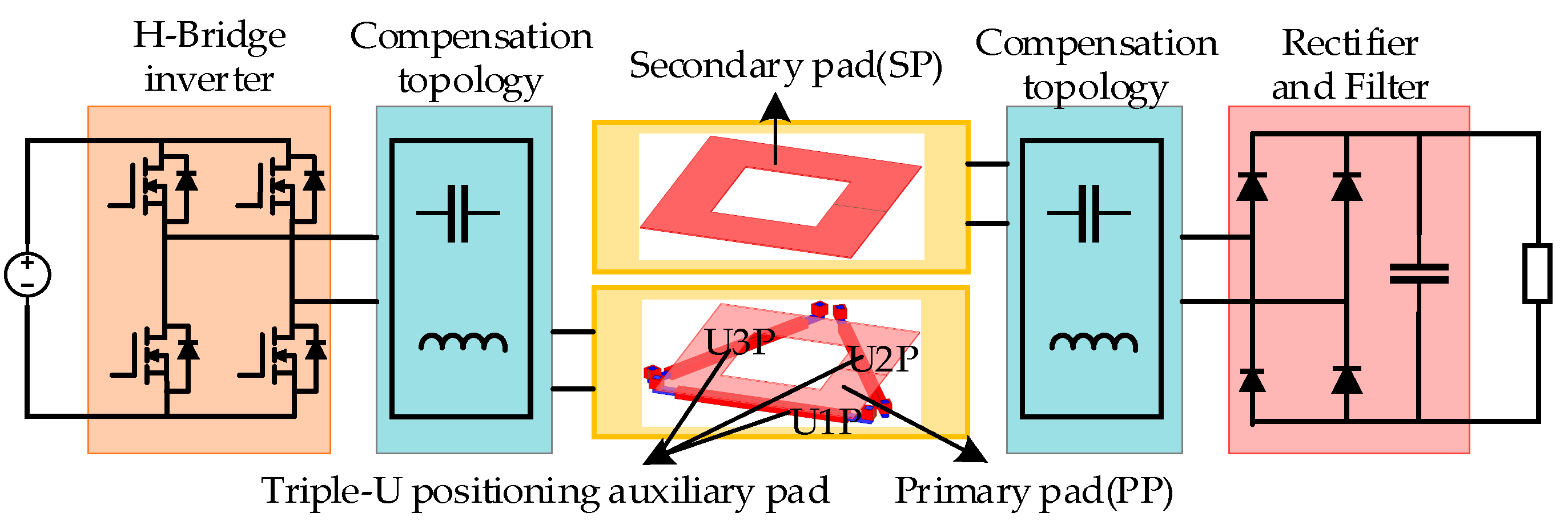
The WPT system can be divided into two parts, as shown in
Figure 1.
A transmitting and positioning subsystem, consisting of a power supply, an inverter, a compensation circuit, a primary pad (PP) and the triple-U positioning auxiliary pad; the proposed triple-U positioning auxiliary pad consists of three U pads U1P, U2P, and U3P. Moreover, the transmitting subsystem could provide power while in the charging state, and the positioning subsystem could realize the detection of the secondary pad position.
An on-board subsystem consists of a secondary pad (SP), a compensation circuit, a rectifier circuit, a voltage regulator circuit, and a load.
Figure 2 shows the structure of the triple-U auxiliary pad involved in the typical magnetic coupler, where both the primary pad and secondary pad are rectangular.
The proposed triple-U auxiliary pad is distributed at the bottom of the primary pad with an equilateral triangle, which can realize both positioning and support. The transmitting and positioning subsystem share the H-Bridge inverter, and the specific work pattern is realized according to the frequency control; the three U pads, U1P, U2P, U3P are controlled at different operating frequencies. During positioning, the three U pads work, respectively, and the corresponding load output voltages VO1, VO2, VO3 are collected in real-time and used as the positioning signals. On the one hand, when the primary pad and secondary pad are aligned, the secondary pad will be in the center of the triple-U auxiliary pad, which indicates that the mutual inductances between the secondary pad and each U pad MU1P-SP, MU2P-SP, MU3P-SP are zero, thus, the corresponding output voltages VO1, VO2, VO3 are zero too. On the other hand, when the primary pad and secondary pad are misaligned, the mutual inductance MU1P-SP, MU2P-SP, MU3P-SP and corresponding output voltages VO1, VO2, VO3 will be different; therefore, positioning can be realized by identifying the trajectory of the three load output voltages.
2.2. Mathematical Model Analysis
The circuit of the WPT positioning system based on triple-U positioning auxiliary pad and LCC-S resonant network is shown in
Figure 3. Where
MU1P-PP,
MU2P-PP,
MU3P-PP are the mutual inductance between the primary pad and the three U pads, respectively;
MU1P-SP,
MU2P-SP,
MU3P-SP are the mutual inductance between the secondary pad and the three U pads, respectively;
MPP-SP represents the mutual inductance between the primary pad and secondary pad,
R and
Req are the load and equivalent load, respectively;
CO represents the filter capacitor,
V1,
V2,
V3, and
VO1,
VO2,
VO3 are the input voltages and load output voltages under the three U pads U1P, U2P, U3P work, respectively.
The fundamental wave analysis method is used for mathematical modeling of the system [
20,
21], and the corresponding circuit resonance conditions are as follows:
During positioning, taking the U1P work as an example, the corresponding circuit in other U pads U2P, U3P, and the primary pad is disconnected. At this time, the system equivalent circuit is shown in
Figure 4.
Under the condition of ignoring the cross-coupling of
Lp1,
L1,
L2,
L3, and combining with (1), it can be concluded from Kirchhoff’s law that the relevant current is:
Considering the influence of the rectifier circuit and the filter capacitor, the equivalent resistance at the secondary side is:
As can be seen from (2) and (3), when the inherent parameters of the pads and the input voltage V1 are determined, the output current IS and the corresponding load output voltage VO1 are positively proportional to the mutual inductance between U pad and secondary pad.
During power transmitting, only the primary pad is at work, and according to the above analysis process, the corresponding loop current is:
The transmission efficiency of the coupler is:
The loss of the WPT positioning system is:
where
PC is the heat loss of the control circuit.
The transmission efficiency of the system is:
4. Positioning Algorithm Based on Feature Trajectory
4.1. Equivalent Mutual Inductance Feature Trajectory Corresponding to U Pad
The frequency control method is adopted to control the triple-U positioning auxiliary pad, and the switching frequency of the three U pads are set as 94.5 kHz, 95.5 kHz and 96 kHz to avoid an influence on the transmission efficiency; meanwhile, the system coupling frequency is set to 95 kHz.
Taking U1P work as an example, the variation of
MU1P-SP with horizontal offset when the gap distance
d = 120 mm is shown in
Figure 7.
MU1P-SP is the mutual inductance between U1P and secondary pad; the
X1O1Y1 shown in
Figure 7 is the sub-coordinate centered on U1P. It can be seen that in any quadrant of the
X1O1Y1 plane,
MU1P-SP will increase and then drop down with the offset of ΔY, and gradually decrease with the offset of ΔX; meanwhile, the value is approximately zero when the secondary pad is located on the
X-axis. Due to the spatial distribution characteristics of the triple-U auxiliary pad,
MU1P-SP,
MU2P-SP and
MU3P-SP generally show a rotation symmetry variation of 120°. Therefore, when the primary pad is aligned with the secondary pad, there is decoupling between the secondary pad and each U pad, which is
MU1P-SP =
MU2P-SP =
MU3P-SP = 0. Moreover, when the primary pad and secondary pad are in misalignment, the mutual inductances are different, that is,
MU1P-SP ≠
MU2P-SP ≠
MU3P-SP.
In addition, taking U1P work as an example, the obtained
MU1P-SP at a certain moment will correspond to the various horizontal offset situations between the primary pad and secondary pad, under these situations, if we project the secondary pad’s center O to the sub-coordinate
X1O1Y1 centered on the U pad, two trajectories with axisymmetric distribution will be formed, which is represented as the equivalent mutual inductance feature trajectory. As shown in
Figure 8, when the projection of the secondary pad’s structure center O is located on the feature trajectory of equivalent mutual inductance,
MU1P-SP is consistent in this case. Moreover, for the sake of a simpler description, we define the corresponding equivalent mutual inductance trajectories of U1P, U2P and U3P to be A, B, and C, respectively.
4.2. Guidance of Optimal Direction under Dynamic Movement
Once the vehicle enters into the recognizable scope, the corresponding load output voltage
VO2 and
VO3 can be detected based on U2P and U3P working, respectively. If
VO2 >
VO3, the secondary pad is located in the second quadrant of the
XOY plane centered on the triple-U pad structure; if
VO2 <
VO3, it is in the third quadrant. The equivalent mutual inductance feature trajectories B and C are obtained relying on
VO2 and
VO3 if B and C intersect at two points, which represents the secondary pad structure center O and exist in two suspicious positions (
x1,
y1) and (
x2,
y2), so the suspect guidance trajectory can be generated according to the position with further distance and then feed back to the driver. On the one hand, the driver modified the position in real-time according to the guidance trajectory B and C, on the other hand, the corresponding output voltage
VO2 and
VO3 are detected by MCU in real time to correct the guidance trajectory B and C. Until the load output voltage
VO1 under U1P working is detected by MCU, which represents that the vehicle has entered the precise positioning area and the specific position (
x,
y) can be obtained to precisely modify the guidance trajectory until the vehicle is in the optimal charging area. The guidance of optimal direction under a dynamic trajectory is shown in
Figure 9.
4.3. Positioning Algorithm Based on Feature Trajectory
The precise detection of vehicle position is realized by comparing the real time measurements with the database built by fitting curves. Combined with the flowchart shown in
Figure 10, the positioning algorithm procedure based on equivalent mutual inductance feature trajectories A, B and C is explained as follows:
Step 1: When the vehicle enters the parking space, the system is switched to positioning mode.
Step 2: Control the specific working status of U1P, U2P, U3P through different frequencies, MCU is working to detect the corresponding load output voltage VO1, VO2 and VO3 in real time. Then the equivalent mutual inductance feature trajectories A, B and C are obtained based on VO1, VO2 and VO3, which are used to determine the current optimal guidance trajectory and judge whether the vehicle is in the precise positioning area. Lastly, feeding back the guidance trajectory to the driver to modify the current position.
Step 3: Repeat Step 2 until the load output voltage VO1 under U1P working is detected by MCU, at this time, there is a unique intersection point (x, y) between the trajectories A, B, and C, from which the vehicle’s specific position (x, y) can be obtained.
Step 4: Modifying the guidance trajectory precisely according to (x, y) until the vehicle is in the effective charging area and then terminates the positioning mode.
5. Experimental Validation
As shown in
Figure 11, a positioning prototype device of the wireless power transfer system with a 120 mm gap distance has been established to verify the scope of identification and accuracy of positioning in the proposed triple-U auxiliary pad. In addition,
Table 1 shows the configuration parameters of the WPT system.
5.1. Mutual Inductance and Load Output Voltage Verification of U Pad
In order to verify the influence of mutual inductance
MU1P-SP,
MU2P-SP,
MU3P-SP between each U pad and secondary pad variation on corresponding load output voltage
VO1,
VO2 and
VO3, we measured the value of
VO1,
VO2 and
VO3 under typical positions; the results are shown in
Figure 12. Meanwhile, for a more intuitive expression of the corresponding load output voltage variation under the three U pads working, respectively, we defined the sub-coordinate
X1O1Y1,
X2O2Y2, and
X3O3Y3, which centered on the corresponding U pad. It can be concluded that the corresponding load output voltage variation of each U pad is consistent with its mutual inductance variation of it. Meanwhile, due to U1P being separate from the ferrite in the primary pad and the other two pads partially coinciding with the ferrite of the primary pad in space, the value of
VO1 is smaller than
VO2 and
VO3 at these positions, while the variation of
VO2 and
VO3 is similar.
5.2. Mutual Inductance and Output Voltage Verification of Typical Coupler with Triple-U Pad
The measurement results of
MU1P-SP,
MU2P-SP,
MU3P-SP,
VO1,
VO2 and
VO3 under the horizontal offset of the
XOY plane centered on the triple-U auxiliary pad are shown in
Figure 13. On the one hand, the maximum relative errors of
MU1P-SP,
MU2P-SP,
MU3P-SP between the measurement and simulation are 9.28%, 9.79%, 9.86%, the minimum relative errors are zero, and the average relative errors are 2.51%, 5.58%, 4.78%. On the other hand, the maximum relative errors of
VO1,
VO2,
VO3 between the measurement and simulation are 9.48%, 9.73%, 9.75%, the minimum relative errors are zero, and the average relative errors are 3.38%, 4.77%, 4.55%. Thus, we can conclude that the measurement of these mutual inductances and load output voltages are consistent with the expected variation, so the proposed triple-U auxiliary pad could be perfectly applied in the positioning and guidance of vehicles.
5.3. Verification of Optimal Direction Guidance
In order to verify the feasibility of an optimal direction-guided trajectory, the initial position of the secondary pad under three conditions is considered in this paper, and the guidance of optimal direction is shown in
Figure 14.
Scenario 1: The secondary pad is located in the second quadrant of the XOY plane centered on the triple-U auxiliary pad, and VO2 > VO3. Firstly, when a vehicle comes into the recognizable range, the three U pads work, respectively, and VO1 = 0 V, VO2 = 14.5 V, VO3 = 11 V are detected in the initial state, so there are blind spots in the secondary pad’s position at this time, and the suspicious position points (−200 mm, 50 mm) and (−190 mm, 30 mm) are obtained by curve fitting. Then the guidance trajectory of the current position is defined, relying on the further point (−200 mm, 50 mm), which is used for modifying the current parking position. During the secondary pad movement, the VO1 is detected, that is, VO1 ≠ 0 V, which indicates that the secondary pad has entered the precise positioning area; we measured the values of VO1, VO2 and VO3 which are, respectively, 0.2 V, 12.03 V, 13.3 V. Therefore, the guidance trajectory is modified in real time according to the dynamic position of the secondary pad until it is aligned with the primary pad.
Scenario 2: The secondary pad is located in the third quadrant of the XOY plane centered on the triple-U auxiliary pad, and VO2 < VO3. When the vehicle drives into the recognizable range, we get the parameters of the corresponding load output voltage that VO1 = 0 V, VO2 = 12.86 V, VO3 = 13 V, and the suspicious position points (−220 mm, −80 mm) and (−160 mm, 20 mm) are obtained by analyzing the corresponding mutual inductance feature trajectory and fitting with the database. Then the guidance trajectory of the current position is defined relying on (−220 mm, 80 mm) to modify the current parking position. Once VO1 ≠ 0 V is detected, the correct position of the secondary pad is determined, and then the guidance trajectory is modified according to the precise position of the secondary pad until it is aligned with the primary pad.
Scenario 3: The secondary pad is located on the −X axis of the XOY plane centered on the triple-U auxiliary pad, and VO2 ≈ VO3. Similarly, when the vehicle drives into the recognizable range, we get the parameters of load output voltage that VO1 = 0 V, VO2 = 13.5 V, VO3 = 13.47 V, and then the suspicious position points (−210 mm, 0 mm) and (−180 mm, 0 mm) are obtained by analyzing the corresponding mutual inductance feature trajectory and fitting with the database. Then guidance trajectory of the current position is defined relying on (−210 mm, 0 mm) to correct the current parking position. The three load output voltages satisfy VO1 = VO2 = VO3 = 0 V, which represents the secondary pad being aligned with the primary pad.
5.4. Positioning Results
The positioning results in the second quadrant of the
XOY plane centered on the triple-U auxiliary pad are shown in
Figure 15. The positioning range is 200 mm × 200 mm with an accuracy of 50 mm and 10 mm, respectively. As shown, 42 cases (68.8% of the 61 samples) have an error of less than 5 mm, 17 cases (27.9%) have an error ranging from 5 mm to 10 mm; 2 cases (3.3%) have an error ranging from 10 mm to 20 mm. These results indicate that more than 95% of the test cases have been well positioned with test errors less than 10 mm and the positioning results are basically consistent with the actual. However, when the secondary pad deviates from the origin in the
XOY plane within 50 mm, the accuracy of positioning has declined due to the tiny variation of mutual inductance in such a position.
The relevant comparison between existing research which uses a camera and auxiliary pad and this paper is shown in
Table 2. Through the structure design of the triple-U positioning auxiliary pad, the magnetic field height and range of positioning auxiliary pad are enhanced and meet the positioning height requirements of different vehicle chassis. The symmetrical distribution of the triple-U auxiliary pad adapts to different magnetic couplers and cannot influence the primary pad. It is obvious that the structure of the triple-U auxiliary pad and the positioning method in this paper has advantages in the wireless power transfer systems of electric vehicles.
6. Conclusions
Intelligent positioning without modification in the secondary pad is one of the pivotal technologies that restrict the practical application of electric vehicle wireless power transfer systems. This paper proposes a novel positioning auxiliary pad and corresponding positioning method that utilizes the inverter and secondary pad configured in the vehicle to achieve positioning. By designing the auxiliary pad with a triple-U structure and analyzing the magnetic field characteristics of a typical magnetic coupler under the intervention of this structure, we obtained the direction guidance trajectory and positioning method. Then, the proposed triple-U auxiliary pad was placed in a rectangular magnetic coupler to verify its positioning feasibility. The results show that the positioning accuracy under this structure is 10 mm, and the recognition range can reach 300 mm × 300 mm. Meanwhile, each U pad is decoupled from the primary pad due to its symmetrical structure, which indicates that the auxiliary pad is suitable for other magnetic couplers. In addition, the proposed triple-U auxiliary pad can effectively solve the limitations of the current positioning methods, such as being too sensitive about obstructions when using the sensor, and too complicated about adding additional pads in the secondary pad, or modifying the secondary pad when utilizing auxiliary pads. In conclusion, the advantages of the proposed triple-U positioning auxiliary pad and corresponding positioning method are mainly reflected in engineering applications, such as: without adding additional pads in the secondary pad or modifying the secondary pad, adapting to a variety of magnetic couplers, which does not affect the primary pad work, and fit for the vehicles with different chassis heights.


