
Design and Performance Analysis of Super Highspeed Flywheel Rotor for Electric Vehicle


Abstract
:1. Introduction
2. Design of Flywheel Rotor Energy and Power Parameters
- (1)
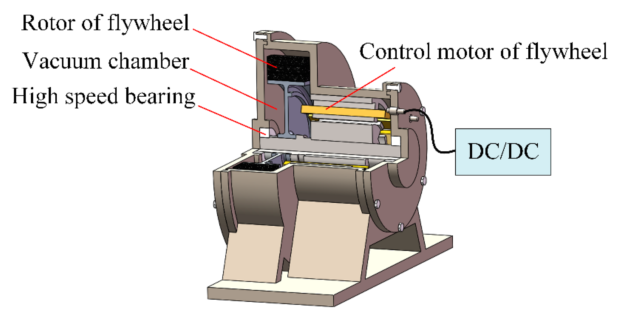
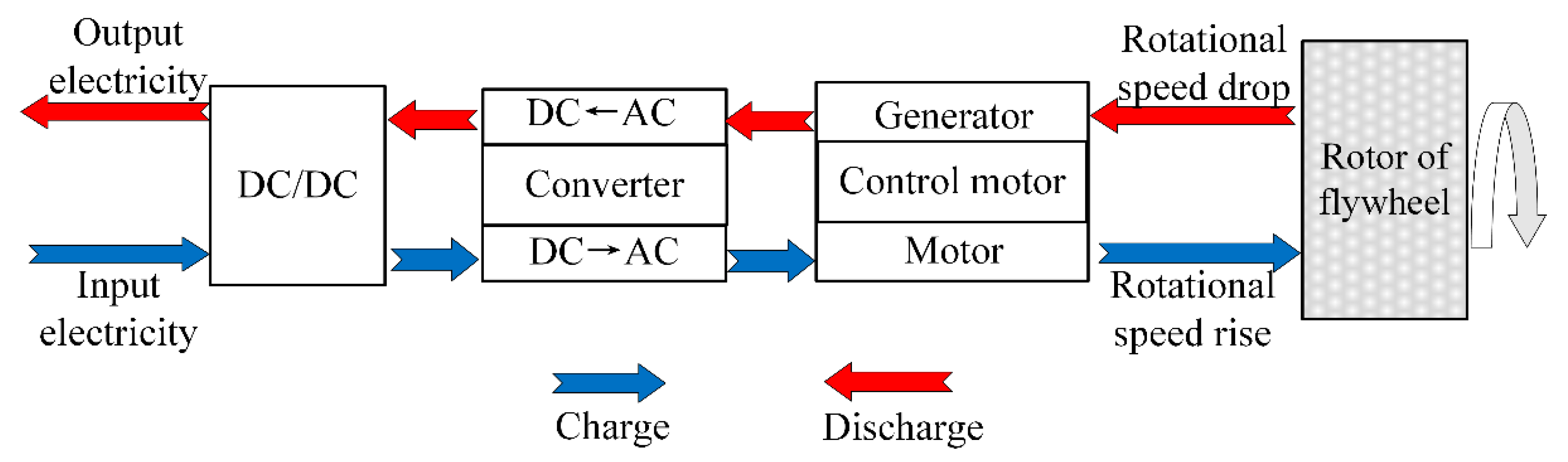
- Charge mode. The flywheel control motor works in the state of the motor. After the DC/DC device processes the electric energy, the flywheel control motor is driven, and the coaxial flywheel rotor is accelerated. The electric energy is transformed into the kinetic energy of the flywheel rotation. The flywheel rotor reaches the maximum design speed and can be filled.
- (2)
- Storage mode. The system has neither energy input nor energy output. Due to the use of a vacuum chamber and electromagnetic bearings, the energy loss is very small, and the flywheel is almost maintained at a certain speed.
- (3)
- Discharge mode. The flywheel control motor works in the state of power generation. When the external load has power demand, the high-speed rotating flywheel drives the coaxial flywheel control motor to rotate. The flywheel control motor generates alternating current, and the kinetic energy of the flywheel rotor is converted into electrical energy. The electrical energy is supplied to the load after rectification and transformation. In this process, the flywheel decelerates. The system no longer releases energy when the flywheel speed reaches the minimum design speed.
2.1. Design of Flywheel Rotor Energy Parameters
2.2. Design of Flywheel Rotor Power Parameters
3. Design of Flywheel Rotor Structure and Material
4. Modeling of Flywheel Rotor Stress with Interference Fit
4.1. Modeling Analysis of Single Layer Composite Wheel Flange Stress
4.2. Modeling of Composite Wheel Flange Stress in Multilayer Interference Assembly
4.3. Flywheel Rotor Stress Analysis
4.3.1. Analysis of Factors Influencing Stress of Flywheel Rotor
4.3.2. Flywheel Rotor Stress Check
5. Conclusions
- (1)
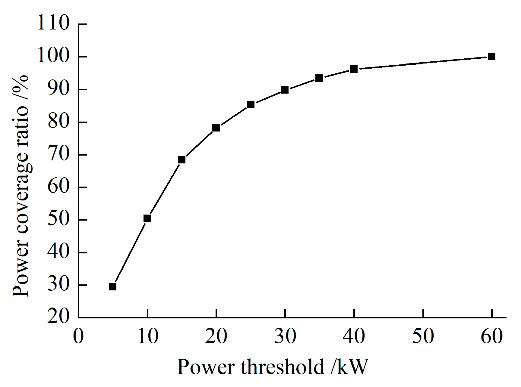
- The selection of the power threshold should try to make the power cover most of the required power of the whole vehicle. If the power threshold is too small, the workload of the flywheel battery will be too heavy. If the threshold value is too high, the flywheel battery will not be able to “cut peaks and make up valleys” for the output power of the lithium battery.
- (2)
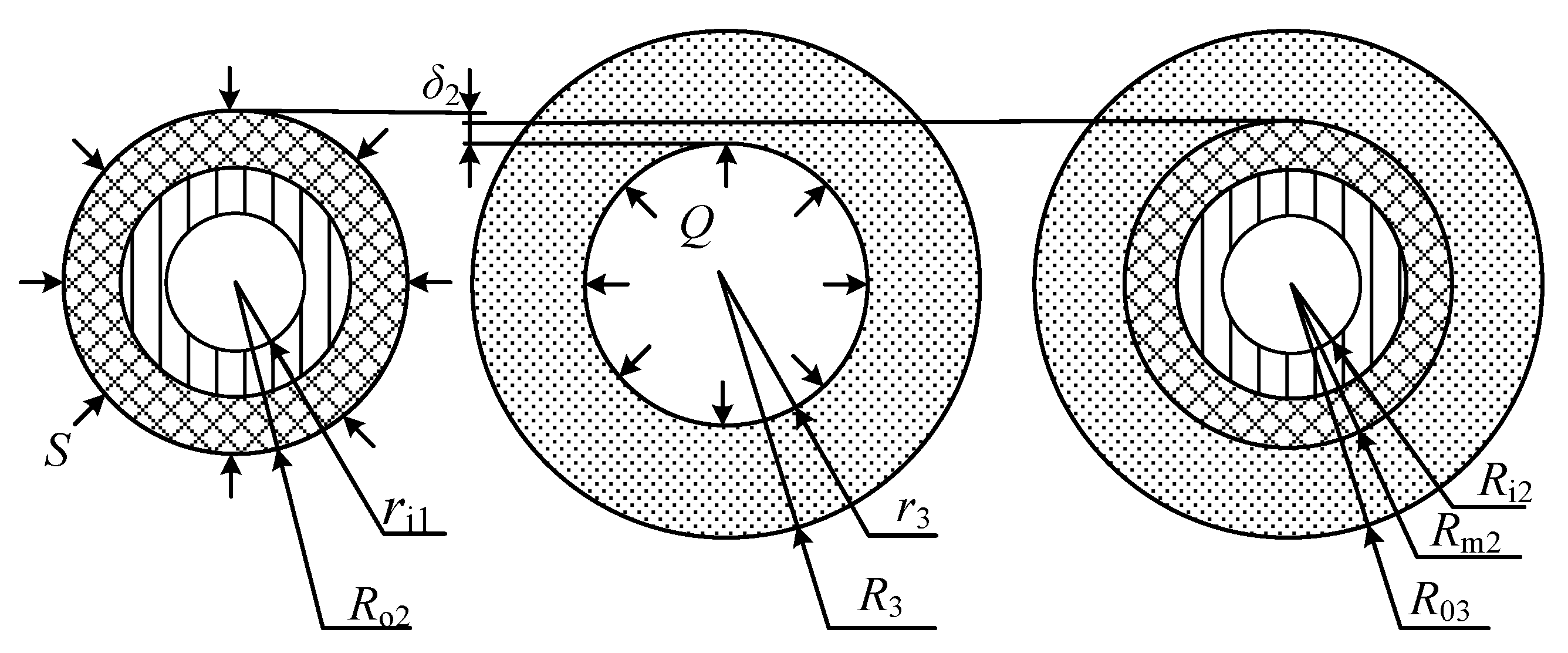
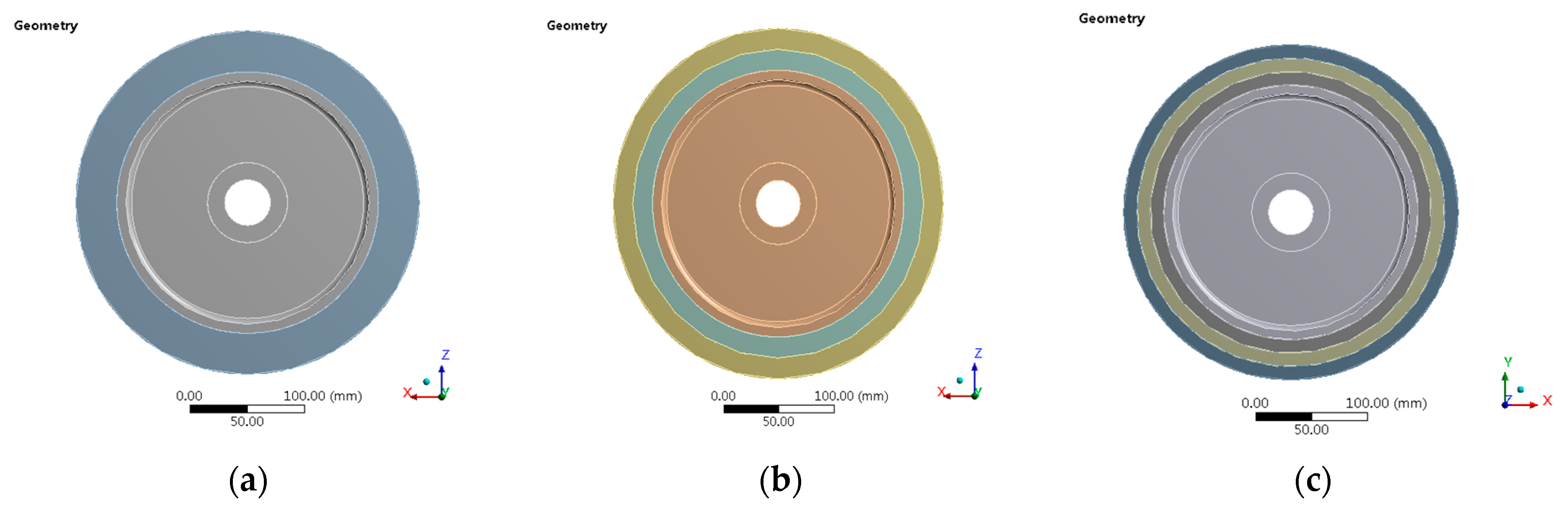
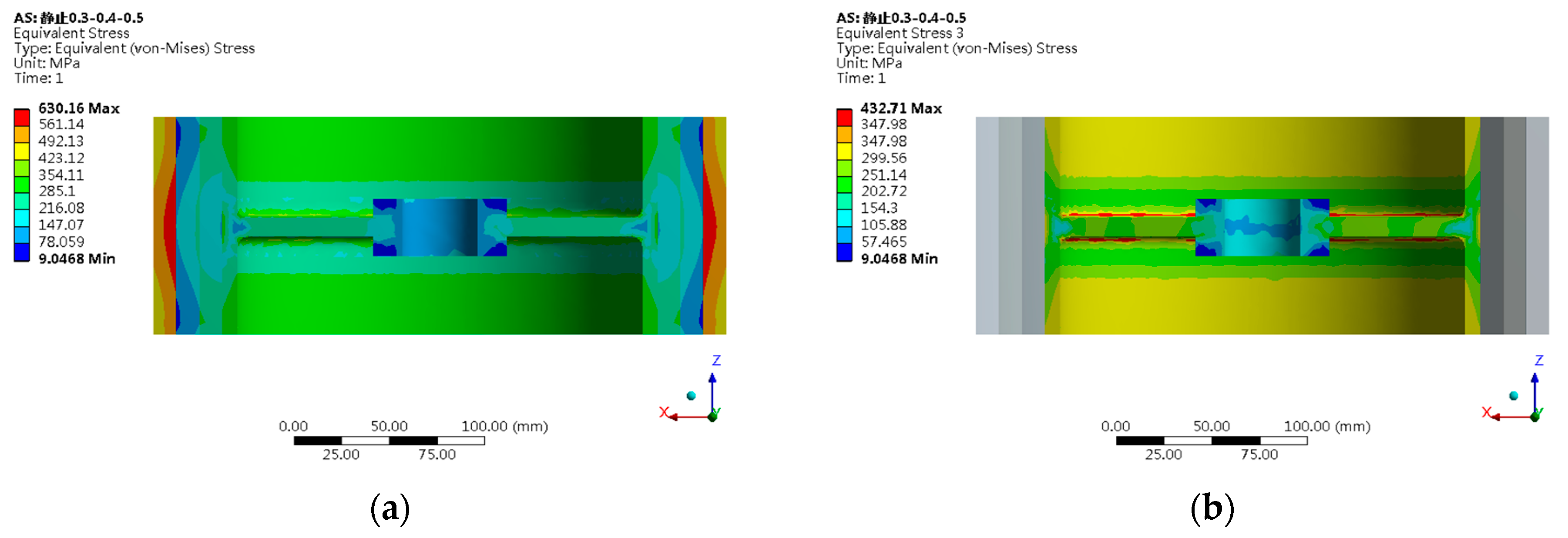
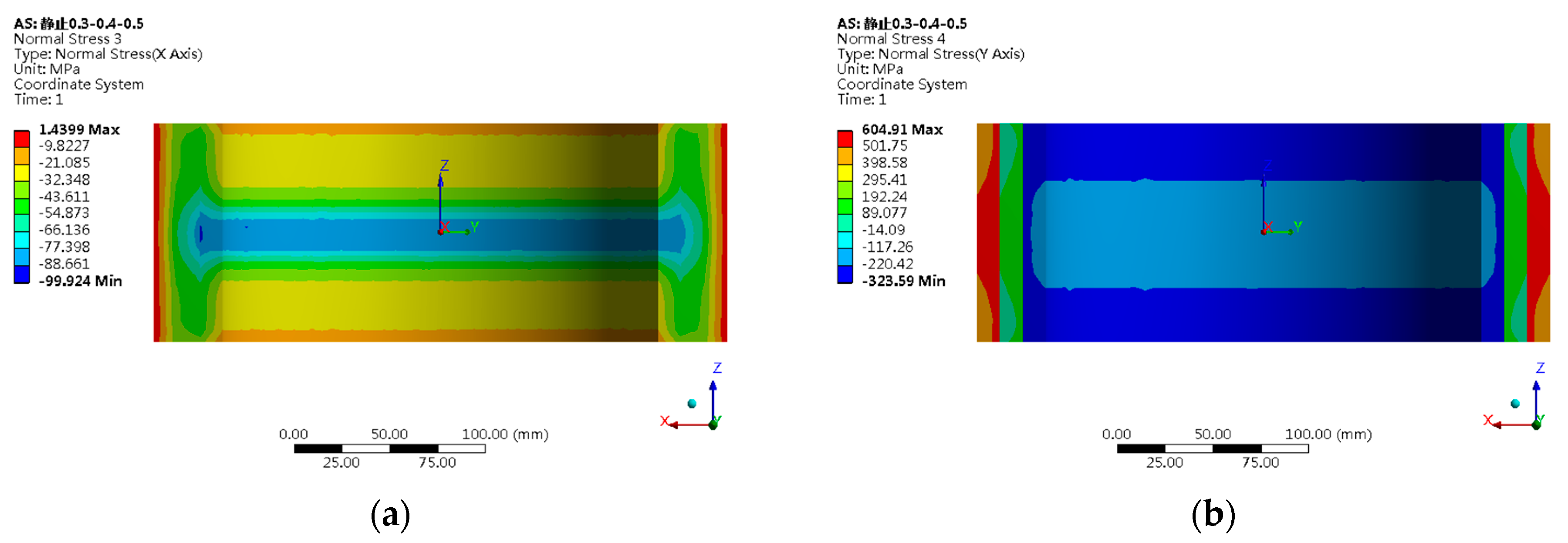
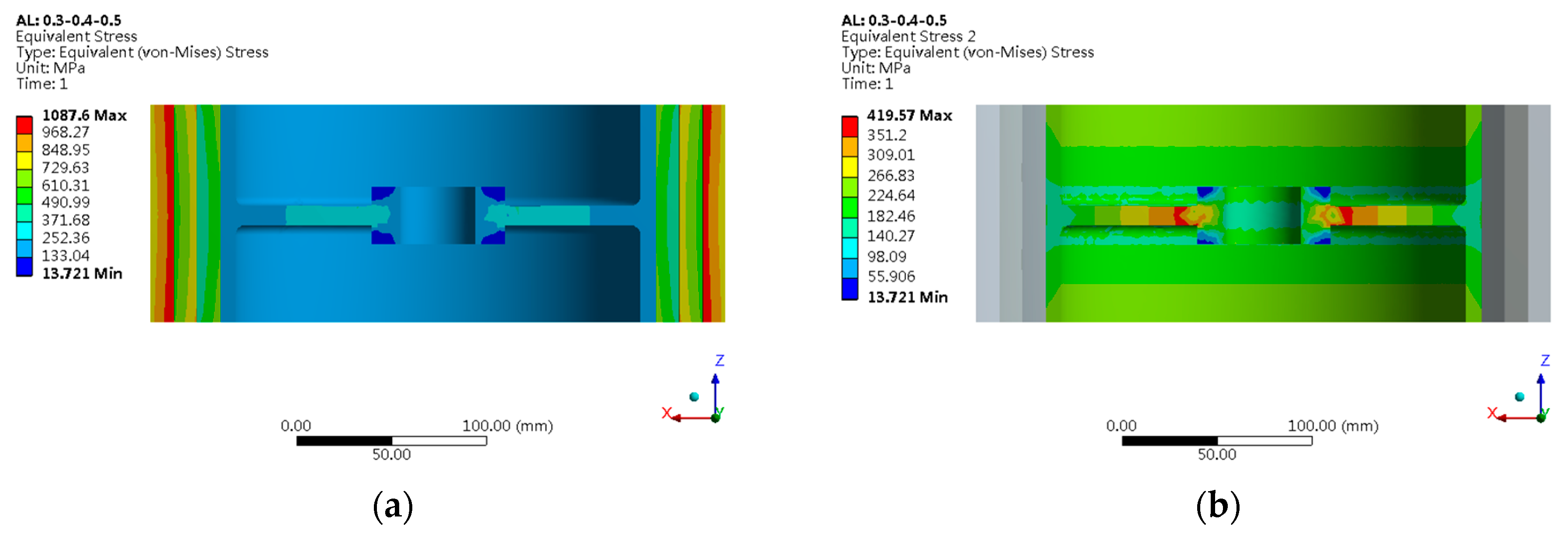
- The radial compressive stress can be generated in the flywheel rotor by using the interference assembly method to improve the radial strength of the flywheel rotor. Still, the increase of the radial strength will sacrifice some of the circumferential strength. Multi-layer interference assembly can improve the flywheel rotor’s stress level, improve the flywheel rotor’s strength, and reduce the machining difficulty of the flywheel rotor. However, the wheel flange cannot be infinitely layered. When there are too many layers, material failure occurs due to excessive radial compressive stress. The three layers interference assembly with a layer thickness of 12 mm is adopted, which can meet the assembly stress requirements of a super highspeed flywheel rotor.
- (3)
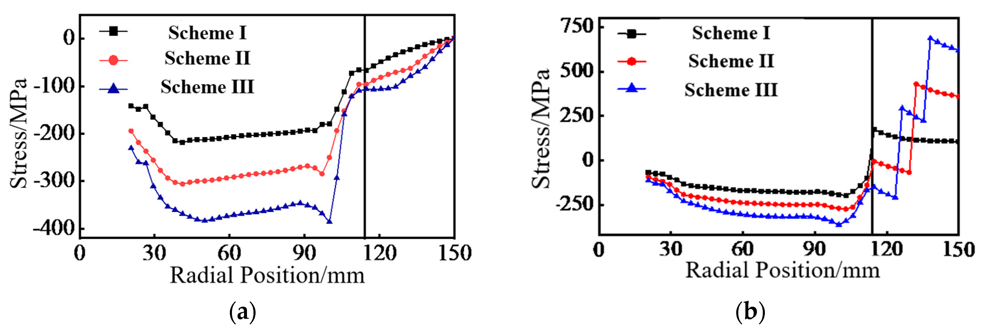
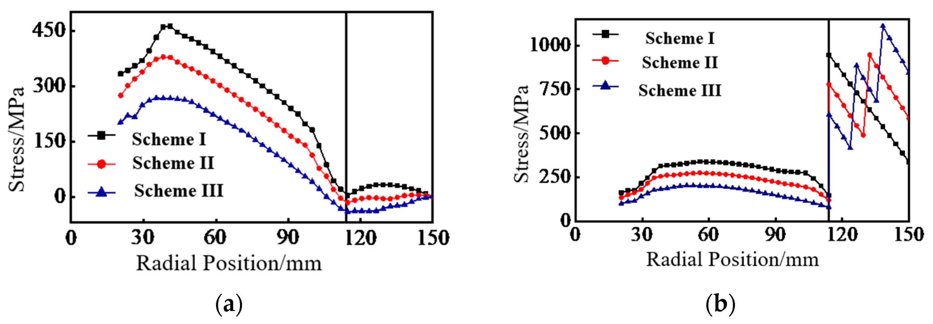
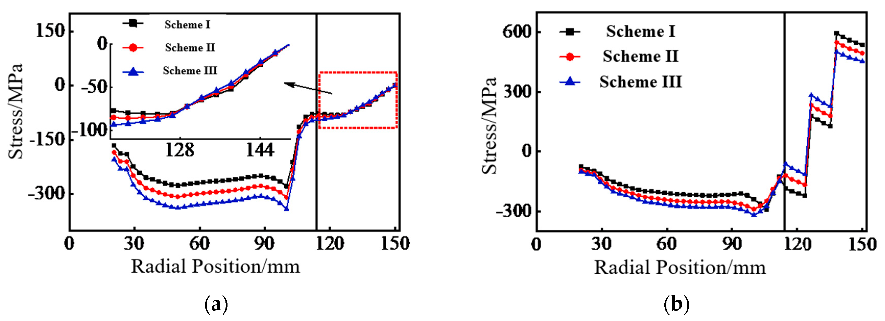
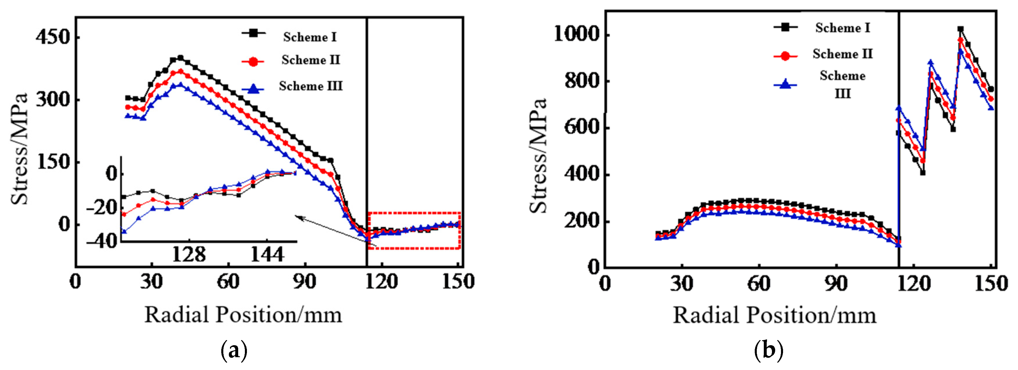
- The hoop stress will jump at the junction of the two layers, and the jump amplitude is proportional to the interference at the junction. The interference between the outer layer and the middle layer will have a great impact on the peak hoop stress. Therefore, it is necessary to decrease the interference at the junction to avoid fatigue failure caused by the long-term stress of the wheel hub.
- (4)
- From the point of view of improving the stress level of the flywheel rotor, when selecting the interference between wheel flange layers of the flywheel rotor, the smaller interference should be selected in the inner layer of the wheel flange, and the larger interference should be selected in the outer layer. The interference between inner layer and wheel hub, middle layer and inner layer, and outer layer and middle layer are designed to be 0.3, 0.4 and 0.5 mm, respectively, which can meet the design requirements.
Author Contributions
Funding
Data Availability Statement
Conflicts of Interest
References
- Hedlund, M.; Lundin, J.; De Santiago, J.; Abrahamsson, J.; Bernhoff, H. Flywheel energy storage for automotive applications. Energies 2015, 8, 10636–10663. [Google Scholar] [CrossRef] [Green Version]
- Yongjie, H.A.; Chong, L.I.; Haoyu, W.A.; Zhengyi, R.E. Analysis of the stresses and displacements for a composites interference fit multi-rim flywheel. Energy Storage Sci. Technol. 2018, 7, 815–820. [Google Scholar]
- Xingjian, D.A.; Kunpeng, W.E.; Xiaozhang, Z.H.; Xinjian, J.I.; Kai, Z.H. A review on flywheel energy storage technology in fifty years. Energy Storage Sci. Technol. 2018, 7, 765–782. [Google Scholar]
- Rupp, A.; Baier, H.; Mertiny, P.; Secanell, M. Analysis of a flywheel energy storage system for light rail transit. Energy 2016, 107, 625–638. [Google Scholar] [CrossRef]
- Wang, Q.; Mah, J.S. The Role of the Government in Development of the Electric Vehicle Industry of China. China Rep. 2022, 58, 194–210. [Google Scholar] [CrossRef]
- Ma, S.C.; Xu, J.H.; Fan, Y. Characteristics and key trends of global electric vehicle technology development: A multi-method patent analysis. J. Clean. Prod. 2022, 338, 130502. [Google Scholar] [CrossRef]
- Sun, B.B.; Gu, T.Q.; Wang, P.W.; Zhang, T.Z.; Wei, S.B. Optimization Design of Powertrain Parameters for Electromechanical Flywheel Hybrid Electric Vehicle. IAENG Int. J. Appl. Math. 2022, 52, 450–457. [Google Scholar]
- Wu, J.; Zhang, J.; Tian, Y.; Li, L. A Novel Adaptive Steering Torque Control Approach for Human–Machine Cooperation Autonomous Vehicles. IEEE Trans. Transp. Electrif. 2022, 7, 2516–2529. [Google Scholar] [CrossRef]
- Kachhwaha, A.; Rashed, G.I.; Garg, A.R.; Mahela, O.P.; Khan, B.; Shafik, M.B.; Hussien, M.G. Design and Performance Analysis of Hybrid Battery and Ultracapacitor Energy Storage System for Electrical Vehicle Active Power Management. Sustainability 2022, 14, 776. [Google Scholar] [CrossRef]
- Ehsani, M.; Gao, Y.; Emadi, A. Modern Electric, Hybrid Electric, and Fuel Cell Vehicles: Fundamentals, Theory, and Design; CRC Press: Boca Raton, FL, USA, 2017. [Google Scholar]
- Itani, K.; De Bernardinis, A.; Khatir, Z.; Jammal, A. Comparative analysis of two hybrid energy storage systems used in a two front wheel driven electric vehicle during extreme start-up and regenerative braking operations. Energy Convers. Manag. 2017, 144, 69–87. [Google Scholar] [CrossRef]
- Huang, C.N.; Chen, Y.S. Design of magnetic flywheel control for performance improvement of fuel cells used in vehicles. Energy 2017, 118, 840–852. [Google Scholar] [CrossRef]
- Hansen, J.G.R.; O’Kain, D.U. An Assessment of Flywheel High Power Energy Storage Technology for Hybrid Vehicles; Oak Ridge National Laboratory: Oak Ridge, TN, USA, 2011. [Google Scholar]
- Arani, A.K.; Karami, H.; Gharehpetian, G.B.; Hejazi, M.S. Review of flywheel energy storage systems structures and applications in power systems and microgrids. Renew. Sustain. Energy Rev. 2017, 69, 9–18. [Google Scholar] [CrossRef]
- Sun, B.B.; Gao, S.; Ma, C. System Power Loss Optimization of Electric Vehicle Driven by Front and Rear Induction Motors. Int. J. Automot. Technol. 2018, 19, 121–134. [Google Scholar] [CrossRef]
- Tutuncu, N. Effect of anisotropy on stresses in rotating discs. Int. J. Mech. Sci. 1995, 37, 873–881. [Google Scholar] [CrossRef]
- Wang, X.C. Design of Carbon Fiber Composite Flywheel; Wuhan University of Technology: Wuhan, China, 2013. [Google Scholar]


| Parameter | Value | Parameter | Value |
|---|---|---|---|
| Circumferential modulus/GPa | 150.7 | Circumferential shear strength/GPa | 5.5 |
| Radial modulus/GPa | 7 | Radial shear strength/GPa | 4.9 |
| Circumferential Poisson’s ratio | 0.3 | Density/kg m−3 | 1590 |
| Radial Poisson’s ratio | 0.33 | Circumferential strength/MPa | 3206 |
| Ultimate Strength/MPa | Elastic Modulus/MPa | Density/kg·m−3 | Yield Strength/MPa |
|---|---|---|---|
| 588 | 2800 | 2760 | 455 |
| Component | Moment of Inertia/kg m2 | External Diameter/mm | Internal Diameter/mm | Height/mm | Quality/kg |
|---|---|---|---|---|---|
| Wheel flange | 0.093 | 300 | 228 | 114 | 5.28 |
| Wheel hub | 0.027 | 228 | 212 | 114 | 2.85 |
| Scheme | Scheme I | Scheme II | Scheme III |
|---|---|---|---|
| Interference between the inner layer and the wheel hub/mm | 0.3 | 0.4 | 0.5 |
| Interference between the middle layer and the inner layer/mm | 0.4 | 0.4 | 0.4 |
| Interference between the outer layer and the middle layer/mm | 0.5 | 0.4 | 0.3 |
Publisher’s Note: MDPI stays neutral with regard to jurisdictional claims in published maps and institutional affiliations. |
© 2022 by the authors. Licensee MDPI, Basel, Switzerland. This article is an open access article distributed under the terms and conditions of the Creative Commons Attribution (CC BY) license (https://creativecommons.org/licenses/by/4.0/).
Share and Cite
Wang, P.; Gu, T.; Sun, B.; Liu, R.; Zhang, T.; Yang, J. Design and Performance Analysis of Super Highspeed Flywheel Rotor for Electric Vehicle. World Electr. Veh. J. 2022, 13, 147. https://doi.org/10.3390/wevj13080147
Wang P, Gu T, Sun B, Liu R, Zhang T, Yang J. Design and Performance Analysis of Super Highspeed Flywheel Rotor for Electric Vehicle. World Electric Vehicle Journal. 2022; 13(8):147. https://doi.org/10.3390/wevj13080147
Chicago/Turabian StyleWang, Pengwei, Tianqi Gu, Binbin Sun, Ruiyuan Liu, Tiezhu Zhang, and Jinshan Yang. 2022. "Design and Performance Analysis of Super Highspeed Flywheel Rotor for Electric Vehicle" World Electric Vehicle Journal 13, no. 8: 147. https://doi.org/10.3390/wevj13080147
APA StyleWang, P., Gu, T., Sun, B., Liu, R., Zhang, T., & Yang, J. (2022). Design and Performance Analysis of Super Highspeed Flywheel Rotor for Electric Vehicle. World Electric Vehicle Journal, 13(8), 147. https://doi.org/10.3390/wevj13080147