Abstract
This paper focuses on the performance analysis, modeling, and control of permanent magnet synchronous generator (PMSG)-based wind energy conversion. This work analyzes controllers for the machine-side converter (MSC) and grid-side converter (GSC) and presents a new direct torque control (DTC) scheme based on a 12-sectors polygonal DTC for variable speed control of the PMSG. The proposed method solves the drawbacks faced by conventional six-sectors DTC control. The proposed method utilizes 12 sectors of 30° each compared to 60° in the conventional 6-sectors DTC. The 12-sectors technique was applied to voltages and flux vectors to increase the degrees of freedom for the selection of optimal vectors and, thus, reduce the torque ripple. This work analyzed the aforementioned DTC methods using MATLAB/Simulink, comparing the dynamic response of the proposed 12-sectors DTC with the conventional 6-sectors DTC control, and the results verified the effectiveness of the proposed DTC control.
1. Introduction
With the global climate problem becoming increasingly prominent, the demand for renewable energy resources is rising. Due to having lower operating costs than other green energy sources, wind energy is considered the most promising form of renewable energy [1].
The double-fed induction generator (DFIG) and the direct-drive permanent magnet synchronous generator (PMSG) are widely used for variable speed wind energy conversion systems (VS-WECS). The PMSG has many advantages and is considered a significant competitor to DFIG. The absence of a gearbox and its full decoupling from the grid, high power density, and easy control mechanism are the main benefits of using the PMSG in VS-WECS [1,2].
The PMSG is connected to the grid by means of a grid-side converter (GSC) and a machine-side converter (MSC). In terms of the control, different control techniques for PMSG-based wind power have been discussed in the literature. Direct torque control (DTC) and field-oriented control (FOC) are the most popular control strategies used in VS-WECS. These two control strategies have been studied and analyzed in previous research [3,4,5], which compared the performance of DTC and FOC based on the space vector modulation (SVM) technique. Prior work introduced an optimized DTC-PWM with constant switching frequency and a dead-time compensation [6].
Furthermore, a previous study introduced a simplified model predictive-DTC (MP-DTC) for PMSG [7], which significantly minimizes the computational effort [8,9]. Moreover, different types of sliding-mode control (SMC) applied to VS-WECS, such as second-order SMC, fuzzy SMC (F-SMC), and integral SMC (I-SMC), have previously been discussed [10,11,12,13]. The results were compared with conventional control strategies and indicated good control effects of the SMCs.
Reference [14] proposed a control strategy for the PMSG wind energy generation system based on vector control theory (VC) for the MSC and GSC. The results showed a good dynamic and steady-state performance. A new control for a grid-connected PMSG-based wind turbine structure was introduced in [15] by using the predictive controllers and state estimators. However, this method needs more parameter tuning efforts. The authors of [16] proposed a new adaptive perturb and observe (AD-PO) and hybrid P&O (HB-PO) for a grid-connected PMSG. A fast-tracking speed with low ripples was achieved using this strategy.
Another previous study proposed a direct power control (DPC) based on SMC for the grid-connected WECS [17] in which the active and reactive power compensation components were simply calculated without engaging the decomposition of positive-sequence voltage and negative-sequence stator current.
Another study proposed a new robust variable-step perturb-and-observe (RVS-P&O)-based MPPT algorithm [18]. The proposed approach was applied to a wind-turbine-based PMSG. The results showed the superiority of the robust variable-step P&O over the competing-based P&O techniques.
This paper focused on the performance analysis, modeling, and control of a PMSG-based WECS, introduced a mathematical model of the complete WECS, and analyzed the MSC and GSC controllers. The six-sectors DTC was applied to the MSC, and some drawbacks that affect system reliability and performance were noticeable, such as high ripples in the electromagnetic torque, current, and flux. To overcome this problem, a 12-sectors DTC control was proposed. This work used a DTC with 12 sectors of 30° each compared to 60° in the conventional 6-sectors DTC and, thus, the switching became more accurate. The proposed controller was verified on a PMSG-based VS-WECS. The simulations were carried out in the MATLAB/Simulink environment, and the characteristics of the PMSG for two different DTC algorithms are discussed and compared to satisfy the best topology in relation to torque, flux ripple calculations, and the spectrum analysis of the stator current.
2. WECS System Modeling
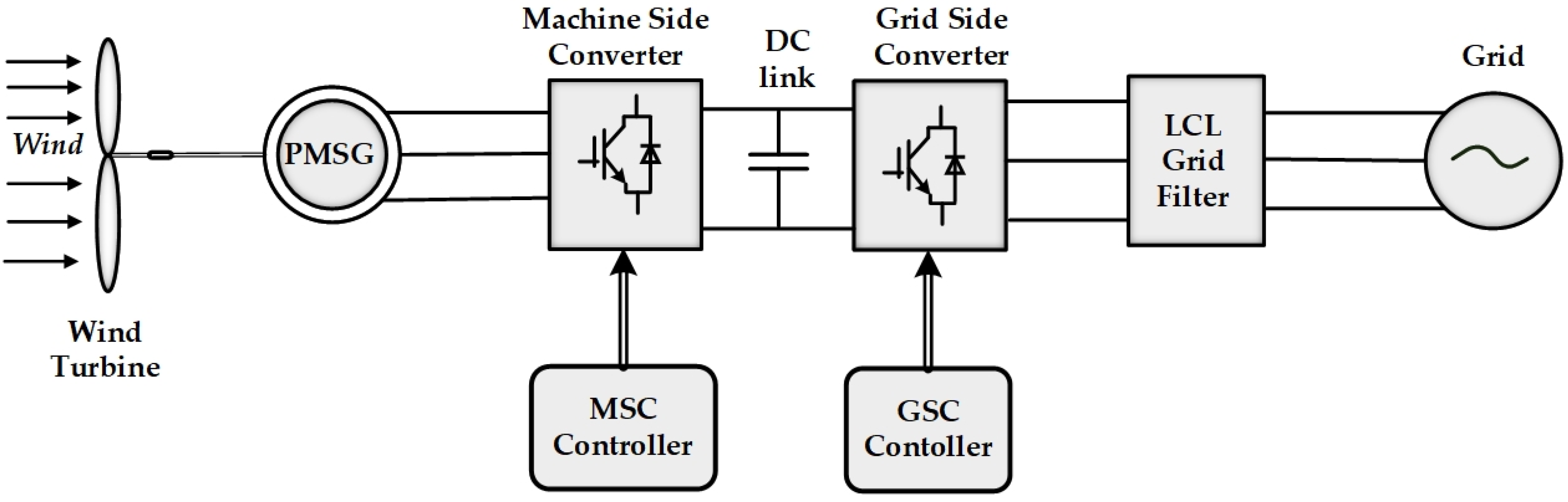
The system configuration of the PMSG-based WECS is presented in Figure 1. The system consisted of a direct-driven PMSG connected to the grid through a back-to-back (BTB) power converter. The BTB power converter had two converters, an MSC, which was designed to achieve the maximum power point tracking (MPPT), and a GSC, which was designed to stabilize the direct current (DC) link voltage at the rated value and control the reactive power.
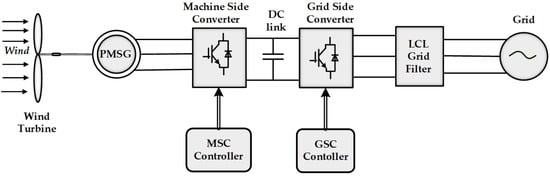
Figure 1.
Configuration of a gearless PMSG-based WECS connected to a grid through a BTB power converter.
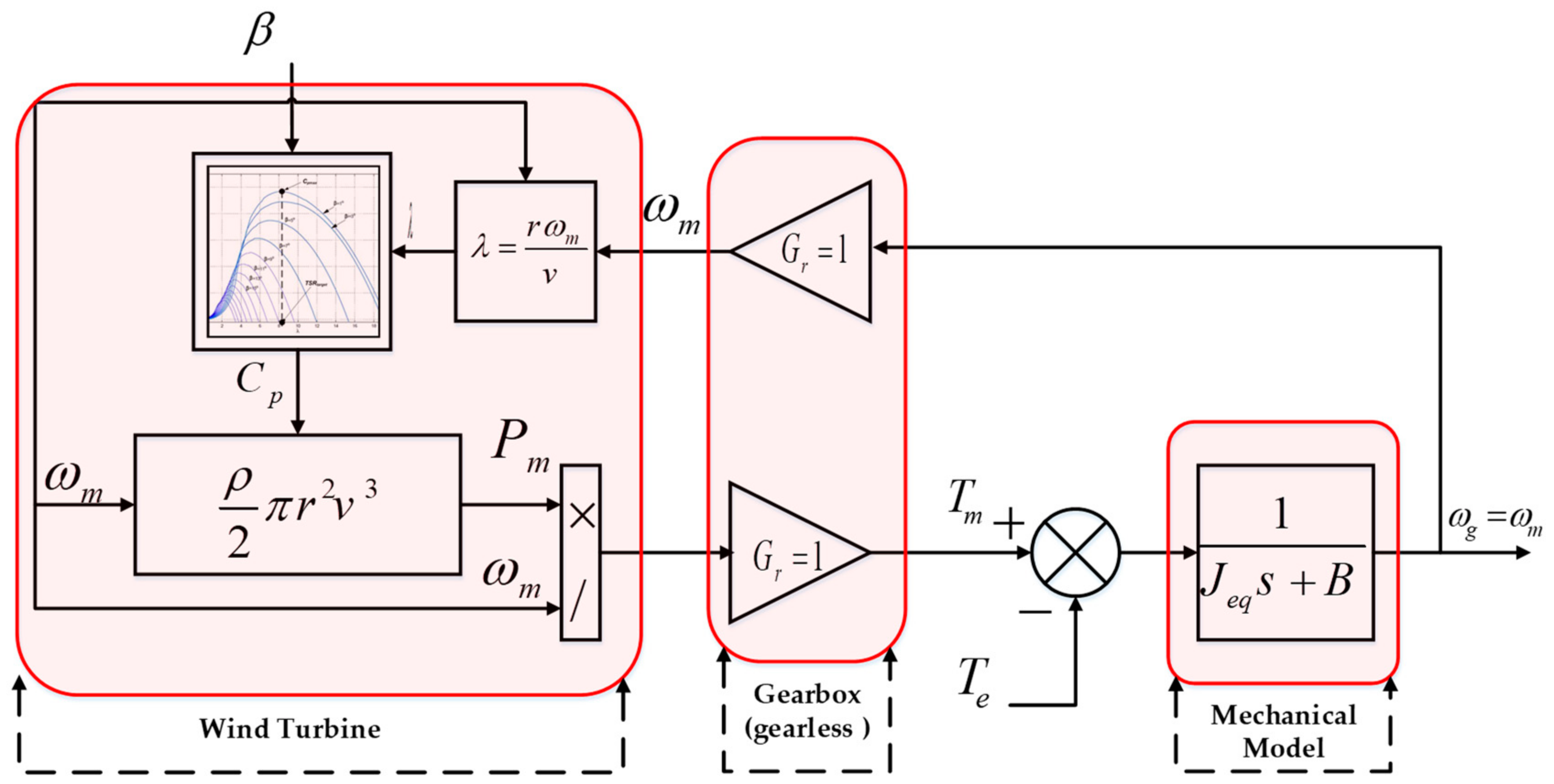
2.1. Mechanical Model of a Wind Turbine
The aerodynamic mechanical power (Pm) as a function of the effective wind speed (v) can be described as follows [19,20]:
where ρ is the air density (1.225 kg/m3); Cp is the coefficient of power conversion; r is the blade tip radius (m); λ is the tip speed ratio (TSR); β is the blade pitch angle in degrees.
The coefficient Cp is a function of (λ, β) and can be expressed as follows [20]:
where ωm is the mechanical rotational speed of the PMSG; ωt is the turbine rotational speed; Gr is the gear ratio (Gr = 1, gearless PMSG); the coefficients c1 to c6 [20] are c1 = 0.5176; c2 = 116; c3 = 0.4; c4 = 5; c5 = 21; c6 = 0.0068.
Assuming a single mass model of the drive train system, the mechanical equation of the wind turbine can be defined as follows:
where Tm is the turbine-driving torque (N·m); Jeq is the total equivalent inertia of the turbine and generator (kg·m2); B is the damping coefficient representing the turbine and generator rotational losses (N·m·s); Te is the electromagnetic torque of the generator (N·m).
The complete block diagram of the dynamic model of the wind turbine is summarized in Figure 2.

Figure 2.
Dynamic block diagram of the wind turbine.
2.2. PMSG Modeling
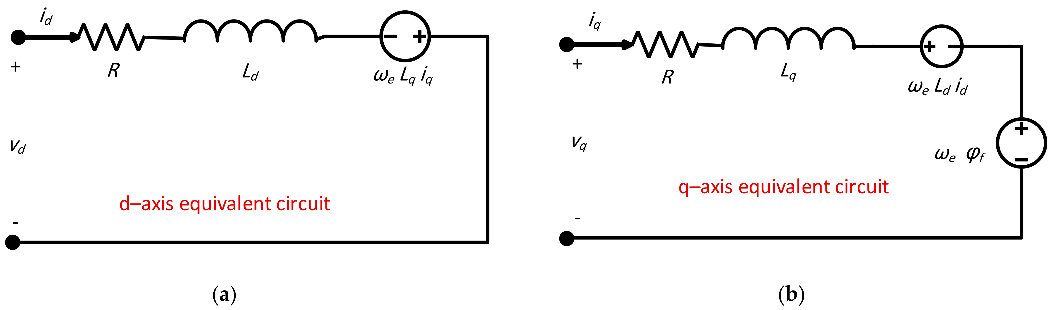
The dynamic model of the PMSG has been reviewed in previous research [21,22,23]. The equivalent circuit of PMSG in the d–q axis reference frame is shown in Figure 3. Based on that, the dynamic voltage equations, vq and vd, expressed in the d–q frame can be written as follows:
where, vq, vd, iq, and id are the d–q axis components of the stator voltages and currents, respectively; R is the stator resistance; Lq and Ld are the d–q axis inductance; φf is the permanent flux linkage; ωe is the electrical rotating speed of the generator. In addition, the electromagnetic torque can be expressed as follows:
where P is the number of pole pairs.

Figure 3.
Equivalent dynamic model of PMSG in (a) d–axis and (b) q–axis.
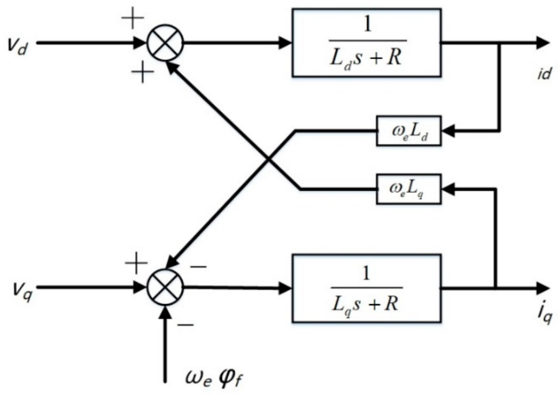
The final dynamic model of the PMSG in the d–q reference frame can be expressed as follows:
According to Equation (8), the block diagram of the dynamic model of the PMSG was derived as shown in Figure 4.
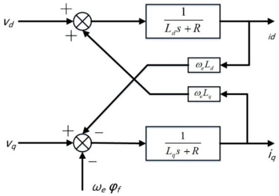
Figure 4.
Dynamic block diagram of the PMSG.
2.3. LCL Filter
Due to the fact of its compact size and better performance in the attenuation of switching ripples, the LCL filter has received significant attention, especially in high-power applications. However, the LCL configuration can lead to resonance and, thus, instability problems [24,25]. Therefore, to ensure stable operation, the controller parameters should be carefully designed.
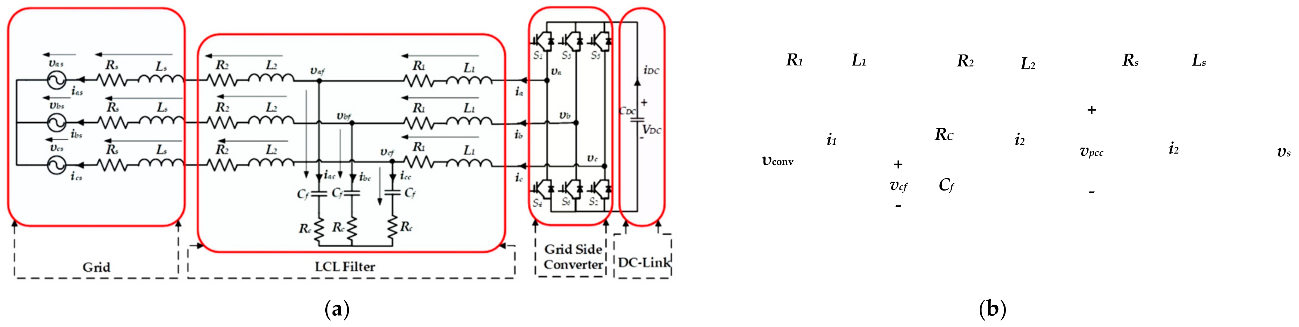
2.3.1. Two-Level Converter with LCL Filter
A three-phase, two-level voltage source converter (VSCs) with an LCL filter is shown in Figure 5a, while Figure 5b presents the equivalent single-phase LCL filter. The LCL filter is composed of the converter-side inductance (L1) and its parasitic resistance (R1), the grid-side inductance (L2) and its parasitic resistance (R2), the filter capacitance (Cf), the capacitor series resistance, and any added damping resistance (Rc). Vconv is the inverter output voltage, vs is the grid-side voltage, Ls and Rs are the inductance and resistance of the source impedance of the grid bus to the point of common coupling (PCC), respectively, and vpcc is the vector of the PCC phase voltage.
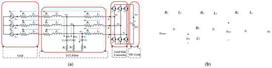
Figure 5.
(a) A three-phase, two–level VSC with an LCL filter and (b) a single–phase LCL filter equivalent circuit.
The dynamic equations for the LCL filter can be written as follows:
Rearranging the differential equations, the state-space model of the LCL filter can be written as follows:
where
and
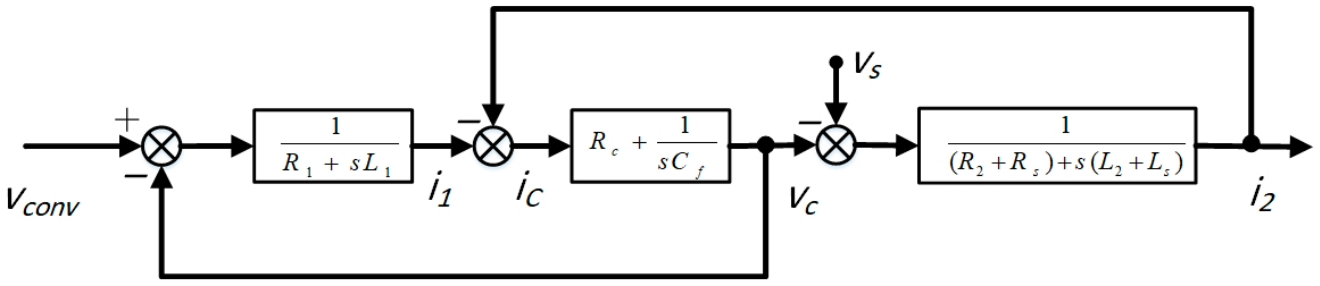
Based on the previous mathematical model, the block diagram of the LCL filter was built as shown in Figure 6.
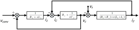
Figure 6.
Laplace domain model of a grid converter with an LCL filter.
2.3.2. Filter Parameters Design
The parameter design of the LCL filter plays an essential role in transmitting high-quality power to the grid. In this paper, the design framework of the LCL filter had three main determinants:
- The converter-side inductor was calculated based on the desired current ripple attenuation;
- The filter capacitance (Cf) was designed based on the filter’s resonance frequency;
- The capacitor series resistance (Rc) was selected based on the required damping factor.
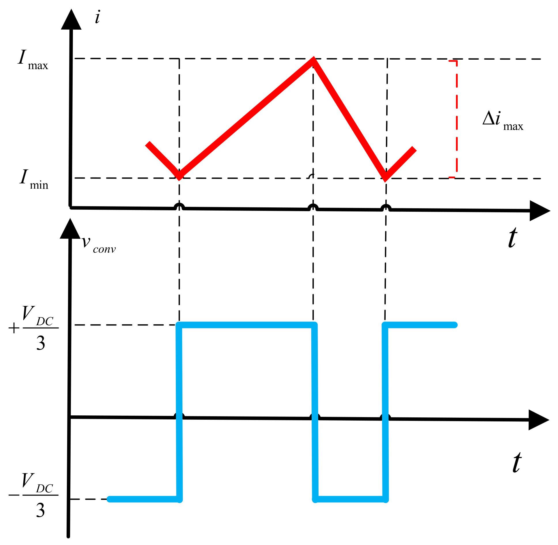
The ripple current (ΔILmax) was derived based on the worst case, where the maximum converter current ripple was obtained during the zero-crossing of the phase voltage [26,27], i.e., when the applied converter voltage varied from to (see Figure 7):
where fsw is the switching frequency and m is the inverter modulation factor.
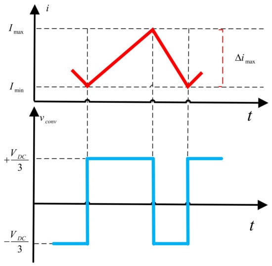
Figure 7.
Current ripple by phase voltage zero-crossing.
By selecting a maximum permissible current ripple (e.g., (ΔILmax = 10%)), the required minimum converter-side inductor can be calculated according to the following equation:
The capacitor (Cf) was designed with the assumption that the reactive power (Q) was less than α% of the rated power (Prat), and α was a positive factor [28,29,30]:
where vs is the stator RMS voltage, and ωg is the grid angular frequency.
The filter capacitor can be calculated as follows:
where Cb is the base capacitance calculated based on the nominal values of the voltage (Vnom), power (pnom), and frequency (ωnom) and x is the percentage of the reactive power absorbed under rated conditions (e.g., x ≤ 5%):
The grid-side inductor L2 was selected according to the grid code requirements related to the harmonic current limits. It can be calculated based on the current ripple attenuation (δ). The current ripple attenuation was defined as the ratio of grid current (i2) to the converter output current (i1):
where .
To avoid resonance problems, the resonance frequency (fres) should be in the range of 10 times the grid frequency (fg) and one-half of the switching frequency (fsw) [31]:
where
Finally, adding a passive damping resistor (Rc) ensures a more stable operation of the LCL filter. According to previous work [31,32], the damping resistor was chosen as one-third of the impedance of the capacitors at resonant frequency:
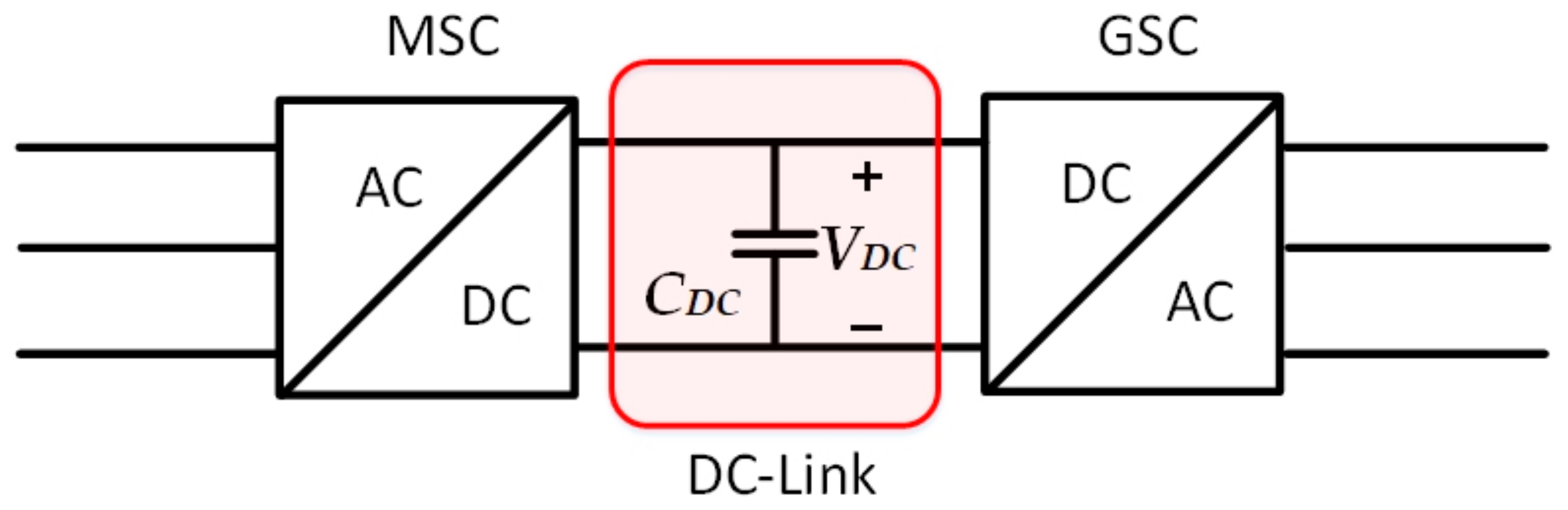
2.4. Modeling of the DC Link
The DC link is represented as a shunt capacitance connected between the MSC and GSC as depicted in Figure 8.
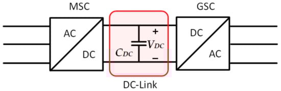
Figure 8.
DC-link model.
The energy stored (WDC) in the DC-link can be estimated as follows:
Based on the maximum permissible voltage ripple, the DC-link capacitance can be selected. The voltage ripple (∆VDC) depends on the DC-link capacitor size and switching frequency. The DC-link capacitor (CDC) is expressed as follows [33]:
where Pnom is the nominal power of the voltage source converter (VSC), and f is the fundamental frequency of the AC power supply. In this work, the allowed DC-link voltage ripple was ∆VDC ≈ 5% of VDC.
3. Control of the GSC
The main purpose of a GSC controller is to stabilize the DC-link voltage and control the reactive power flowing from or to the grid, i.e., the unity power factor [34]. The active and reactive power can be controlled by the direct and quadratic current using grid voltage-oriented control (VOC). On the VOC, the grid voltage is aligned to the d-axis, as depicted in Figure 9, allowing for decoupled control of the active and reactive power flowing between the GSC and the grid.
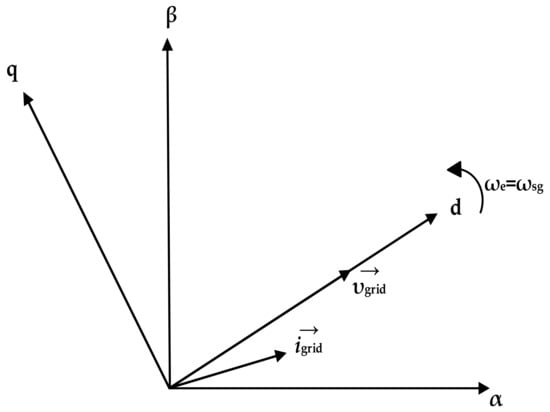
Figure 9.
Schematic of the space vectors.
The detailed control structure of the VOC is shown in Figure 10. Two inner and outer loops were used to control the GSC. The outer loop was used to adjust the DC-link voltage and the reactive power for the grid side, while the inner loop was used to control the power at the grid side.
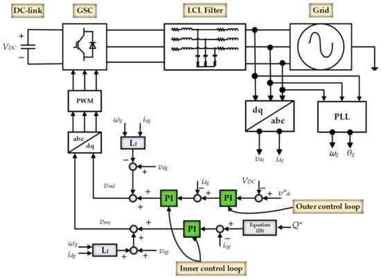
Figure 10.
Voltage-oriented control of the GSC.
Assuming the LCL filter resonance frequency was much lower than the switching frequency, the LCL filter can be considered an RL filter [24,35]. Based on this approximation, the resistance and inductance of the modified model of the LCL filter can be expressed as:
where Rf and Lf are the resistance and inductance of the equivalent RL filter, respectively.
Using the modified filter model, the voltage and current relationship between the grid and the converter output can be expressed as follows:
where vdg and vqg are the dq-axis components of the grid voltages; idg and iqg are the dq-axis components of the grid currents; vdi and vqi are the dq-axis components of the converter voltages.
While decoupled active and reactive power control was performed by aligning the grid voltage to the d-axis (i.e., ), the active and reactive power was solely related to the d-axis and q-axis current through the grid filter:
where Pgrid and Qgrid are the active and reactive powers of the grid-side converter, respectively.
The DC-link voltage can be easily controlled through the d-axis current, idg, as follows:
Furthermore, the synchronous reference frame phase-locked loop (SRF-PLL) was used to calculate the grid-side phase angle (θg) and grid angular frequency (ωg). As the d-axis grid voltage was aligned to the d-axis, the calculated angle was adjusted until the q-axis grid voltage became zero.
As previously mentioned, the GSC controller scheme was implemented with two current-control loops. Firstly, the d-axis current was used to regulate the DC-bus voltage. The difference between the reference and the measured values of the DC-link voltage was amplified by the PI regulator, resulting in the d-axis current reference (). Subsequently, the igd was controlled to track the through the PI regulator. A compensation (decoupling) was used to eliminate the coupling between the d-axis and q-axis current controls. Based on that, the output of the PI regulator was added to a compensation term and, thus, the d-axis reference voltage of the converter vmd was obtained.
The second control loop was the reactive-power control loop, which was controlled through the q-axis current, iqg, see Figure 10. The q-axis current reference () was calculated based on (28). A PI regulator was used to control the q-axis current (igq). Finally, the q-axis reference voltage of the converter (vmq) was obtained by adding the output of the PI regulator to the compensation term. Once the reference voltages vmq and vmd were obtained and transformed into the abc frame, the PWM pulses were generated and fed to the grid converter.
4. Direct Torque Control (DTC)
4.1. Conventional 6-Sectors DTC
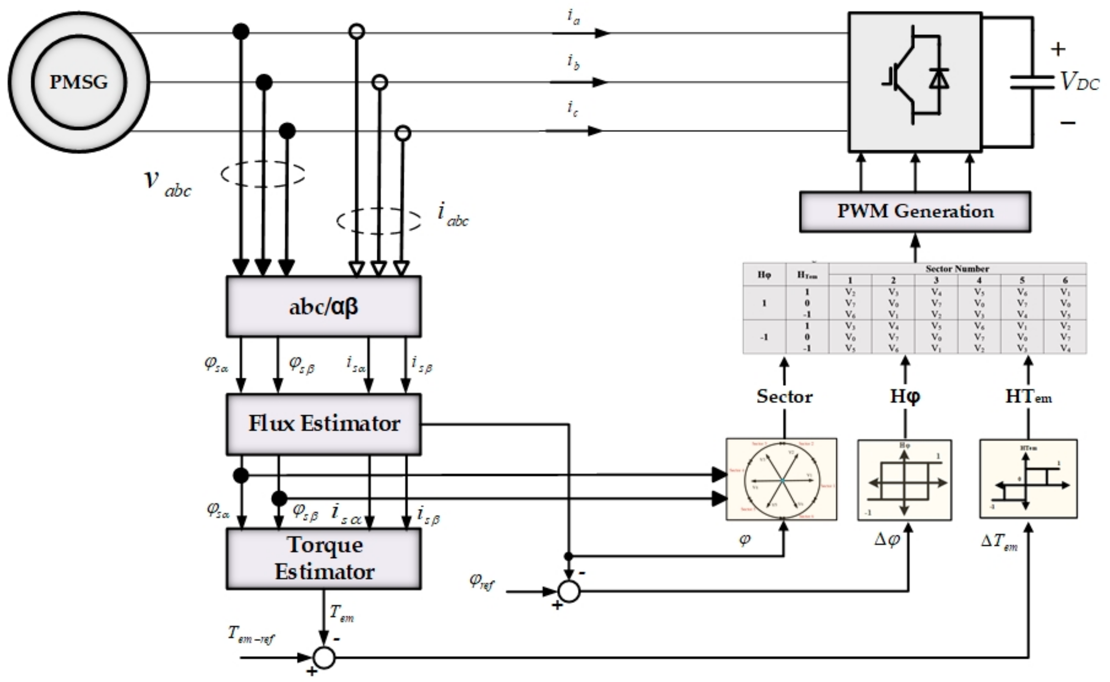
DTC directly controls the stator flux and electromagnetic torque by selecting the appropriate converter state. A complete block diagram of the DTC is shown in Figure 11. As shown, the reference values for the stator flux and electromagnetic torque were compared to the estimated values to produce the error of the stator flux and torque, which were transferred to their respective hysteresis comparators.
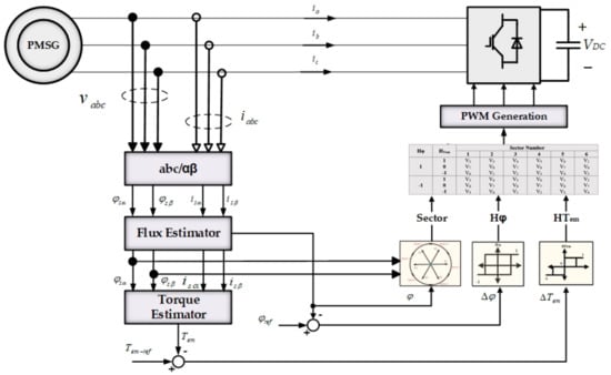
Figure 11.
Conventional 6-sectors DTC.
The stator flux was controlled through a two-level hysteresis comparator, while the electromagnetic torque was controlled using a three-level hysteresis comparator as shown in Figure 12.
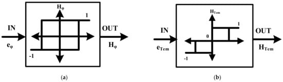
Figure 12.
(a) A two-level hysteresis comparator for stator flux control and (b) a three-level hysteresis comparator for torque control.
The hysteresis comparators generate the required hysteresis band of flux and torque, and then the optimal vector voltage is selected. In this case, the optimal vector voltage was generated by the MSC to track the required increase or decrease in the torque and flux variables.
As shown in Figure 12, the output of the torque hysteresis band controller is represented by the variable HTem, which refers to increased (HT = 1), decreased (HT = −1), or constant (HT = 0), depending on the input.
Since the DTC keeps the amplitude of the stator flux vector at a near-constant value for fixed time intervals, and assuming that the stator resistance (R) voltage drop was neglected (i.e., the stator voltage remained constant), the stator voltage directly affected the stator flux according to the following equation:
By selecting the right voltage vector () for each time interval (∆t), it is possible to estimate the flux () and, thus, the electromagnetic torque can be calculated as a result of the equation presented below (34). The voltage vector plane was divided into six sectors, as shown in Figure 13, while the optimal voltage vector was selected based on the switching table shown in Table 1.
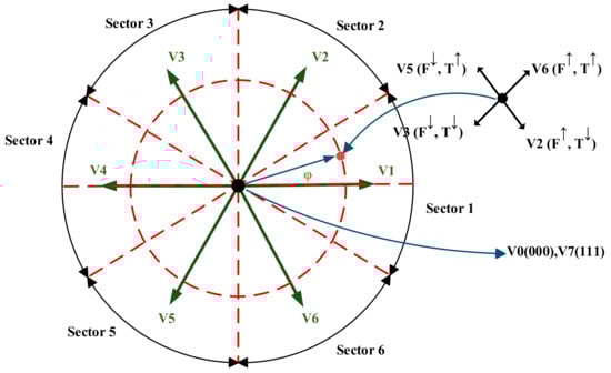
Figure 13.
Voltage vectors in the 6-sectors DTC.

Table 1.
Switching Table of the 6-sectors DTC.
4.2. Torque and Flux Reference Values Definition
It is well known that the stator flux can be estimated through the voltage and current of the stator [1].
where φsα and φsβ are the αβ-axis components of the stator fluxes; vsα and vsβ are the αβ-axis components of the stator voltages; isα and isβ are the αβ-axis components of the stator currents, see Figure 9.
Based on Equation (31), the magnitude ( and angle position of the stator flux vector () can be calculated as follows:
The flux reference (φref) was obtained using a lookup table. The lookup table provides the φref as a function of the speed (ωr). In this work, the flux was assumed as a constant value, rated value (φrated), during the operation in the range of the nominal speed (ωnom). Conversely, as the speed becomes higher than the base speed, the flux should be reduced:
The torque reference is generated from the speed controller and then compared to the estimated torque. In this paper (see Section 5), the torque reference was assumed to be constant over a certain interval of time and modeled as a time step function. According to previous research [1,36], the electromagnetic torque can be estimated as follows:
4.3. Proposed 12-Sectors DTC of the PMSG
The main disadvantages of the conventional 6-sectors DTC are the variable switching frequency, the high-current total harmonic distortion (THD), the high torque ripples, and the problem of flux drop at low speeds [37,38].
Furthermore, in conventional DTC, two states of presented torque are not used (see Table 1). The voltage vectors V1 and V4 do not exist in the first sector, and that is right for the other sectors with different voltage vectors. This leads to inaccuracy in the torque and flux within a 60° sector. In this paper, to overcome these drawbacks, a 12-sectors DTC is proposed, where the sector number is increased to 12 sectors of 30° for each sector rather than 60°.
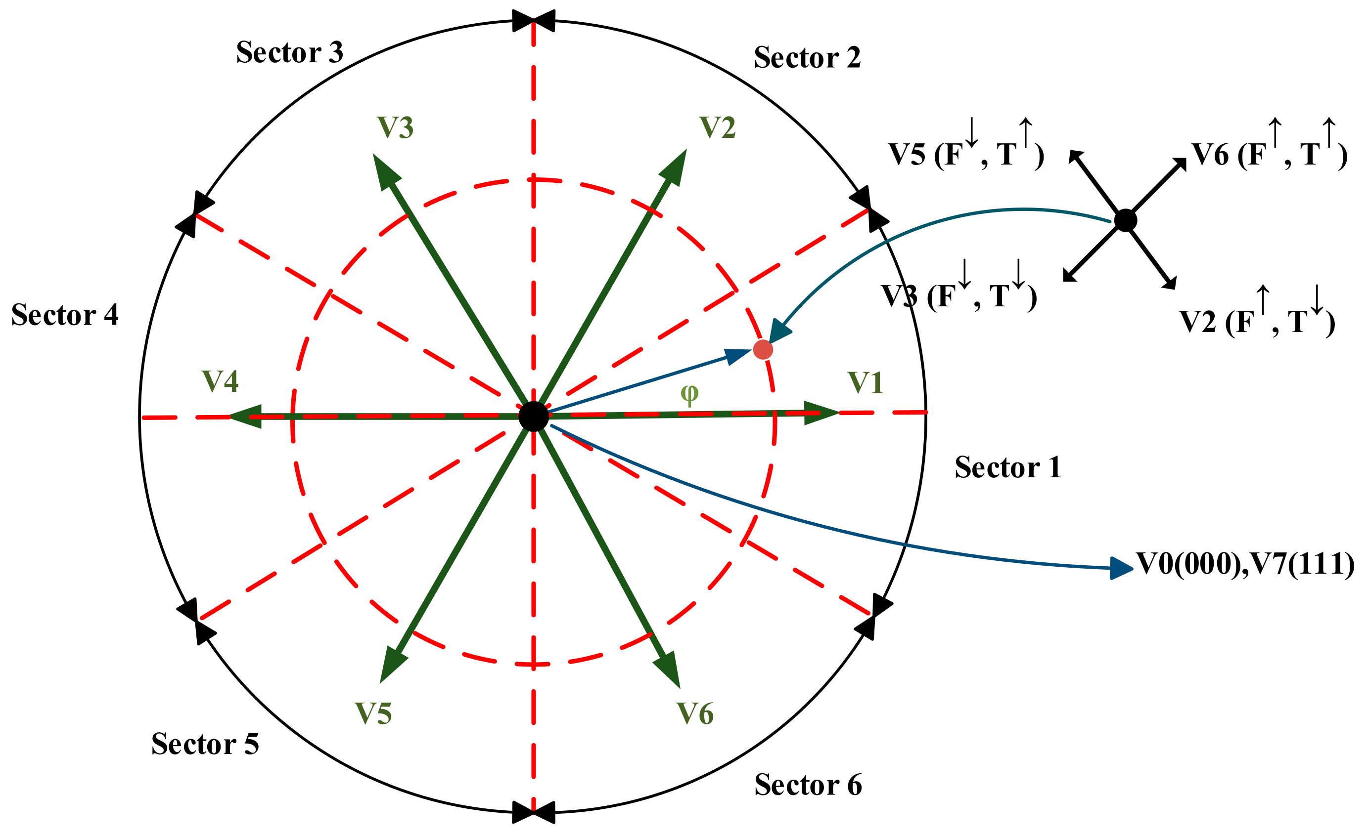
Table 2 shows the possible voltage vector combinations in the proposed 12-sectors DTC technique, where HTem = 2,−2 (T↑↑, T↓↓) represents a large increase and decrease in torque; HTem = 1, −1 (T↑, T↓) represents a small increase and decrease in torque; Hφ = 1, −1 (φ↑, φ ↓) represents an increase and decrease in flux. The voltage vector plane was divided into 12 sectors, as illustrated in Figure 14.
Table 2.
Switching table for the proposed 12-sectors DTC.
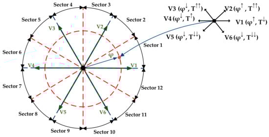
Figure 14.
Voltage vectors in the proposed 12-sectors DTC.
Generally, the sector (sx) can be determined as follows:
where m is the sector number (m = 1, 2, …, 12).
In this approach, a four-level hysteresis comparator was applied to the torque, and a two-level was used for the flux. The following conditions were used in the torque comparator:
where HTem is the torque status signal; ΔTem is the difference between the reference and actual values of electromagnetic torque (; HBT is the hysteresis band of the torque.
5. Results and Discussion
To verify the proposed 12-sectors DTC control strategy, a MATLAB/Simulink-based simulation was carried out. The nominal parameters of the 3.5 kW system are listed in Table 3.
Table 3.
3.5 kW PMSG parameters.
In the simulation, the torque hysteresis band was selected as 5% Tn, and the flux hysteresis band value was set at 2%φ. The DC-link was kept at approximately 1200 V. The sampling time of both DTC algorithms was 50 μs.
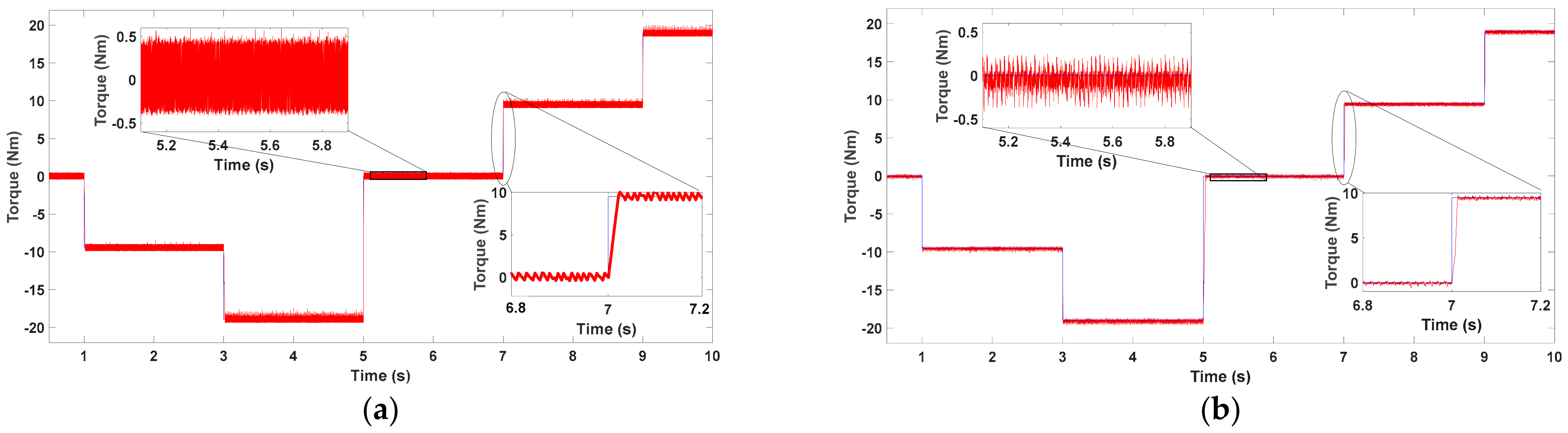
The reference torque was selected as a function of time, as depicted in Figure 15. As shown, for the conventional 6-sectors DTC and the proposed 12-sectors DTC, the simulated torque followed its reference well, with notable ripples. Conversely, the reference was reached quickly, i.e., settling time ≈ 810 μs for the 6-sectors DTC and ≈700 μs for the 12-sectors DTC. This confirms the advantages of the fast torque response of DTC techniques.
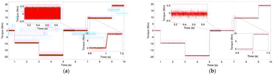
Figure 15.
Electromagnetic torque response with (a) 6−sectors and (b) 12−sectors DTC control strategies.
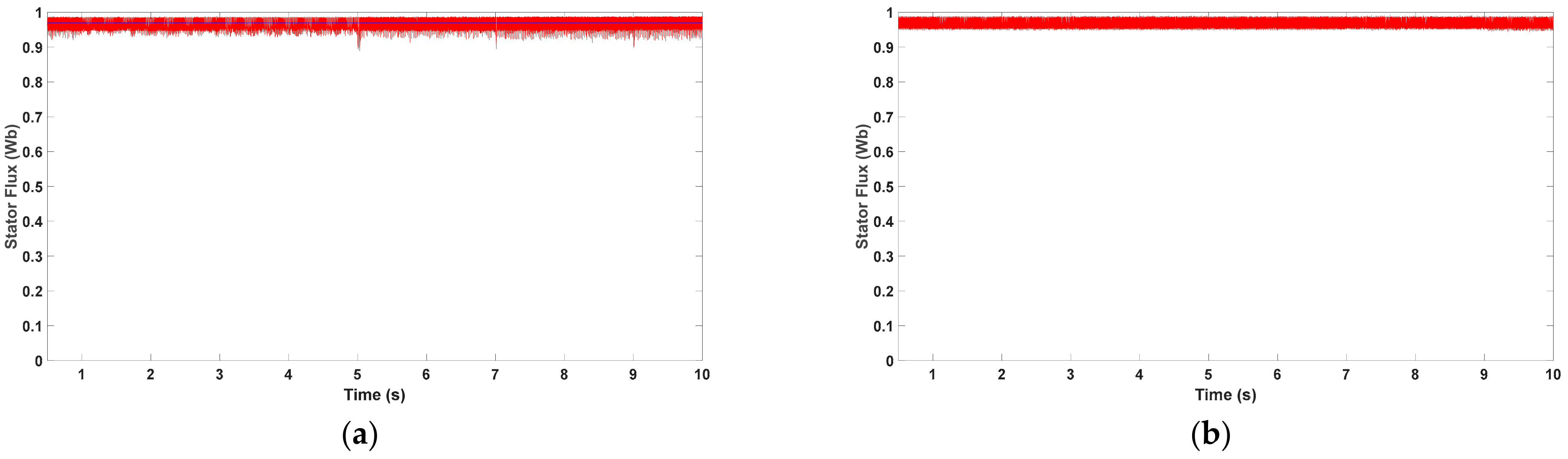
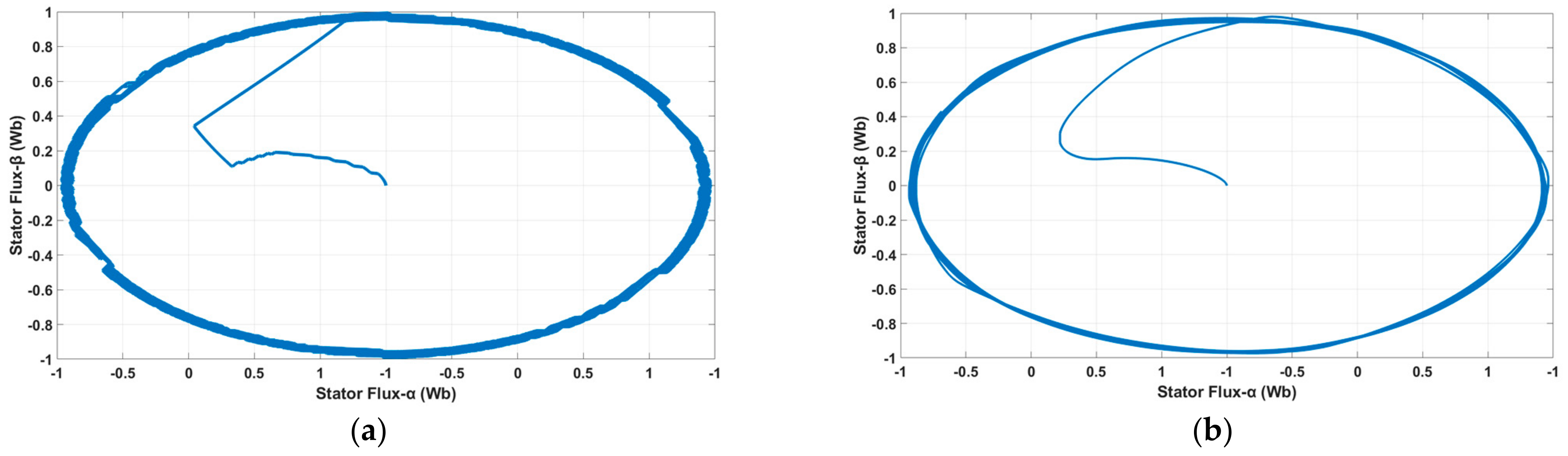
Further, Figure 16 depicts the stator flux, which attracted its reference well. The trajectory of the stator flux vector is presented in Figure 17. From Figure 17, it is clear that the stator flux vector rotated with a constant magnitude and small oscillation.

Figure 16.
Stator flux response with (a) 6-sectors and (b) 12-sectors DTC control strategies.
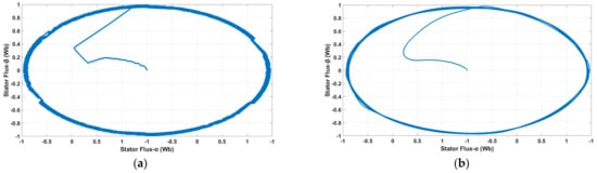
Figure 17.
Stator flux trajectory with (a) 6−sectors and (b) 12−sectors DTC control strategies.
However, the main drawback of DTC is the ripple in torque and flux due to the variable switching frequency. As shown in Figure 15, in the comparative results between the 6-sectors and 12-sectors DTCs, the dynamic responses were almost the same, but the torque and flux ripples during transient and steady-state were clearly reduced in the proposed 12-sectors method.
Table 4 presents the ripples percentage of torque and flux at different reference torque values. As expected, both DTC algorithms had ripples in torque and flux, and it is clear that the 12-sectors DTC had the best performance, as the ripples were significantly reduced over a wide operation range.
Table 4.
Comparative analysis of torque and flux ripples for different DTC algorithms.
In the conventional 6-sectors DTC, and due to the fact that two states of the presented torque were not used, the torque control was ambiguous. This resulted in high ripples in the torque and flux, see Table 4.
Conversely, applying the 12-sectors strategy guaranteed that all voltage vectors were used and, therefore, the switching was more accurate and had a good dynamic response.
Further, using twelve 30° sectors for voltage and flux vectors and applying the four-level hysteresis comparator (i.e., a large increase and decrease, a small increase and decrease in torque) provided additional degrees of freedom to select the optimal voltage vectors. This was mainly because the number of sectors was the most influential factor in reducing ripples and, hence, smooth operation.
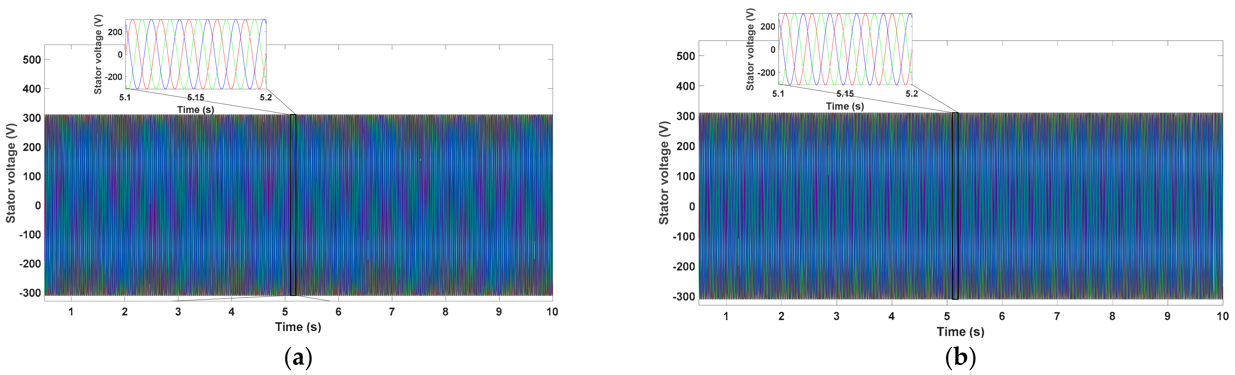
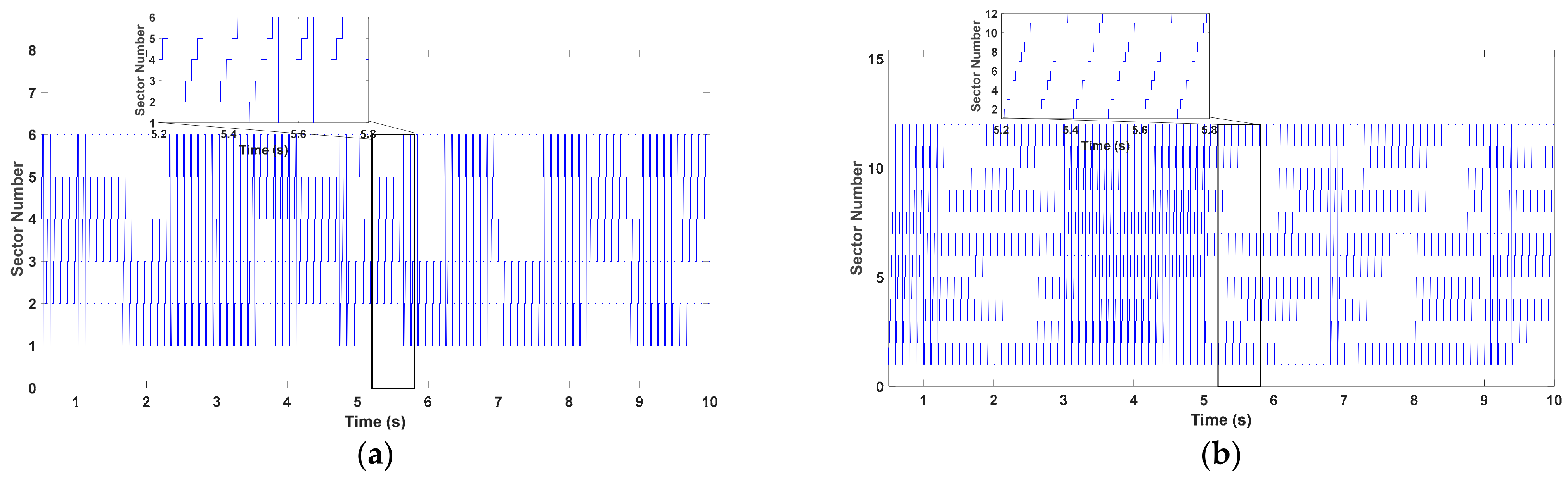
The steady-state response of the stator voltages is presented in Figure 18. Figure 19 presents the stator flux sectors for both techniques, where the main difference is the sectors’ division with respect to time.

Figure 18.
Stator voltage response with (a) 6−sectors and (b) 12−sectors DTC control strategies.
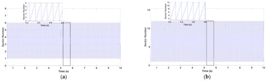
Figure 19.
Stator flux sectors with (a) 6−sectors and (b) 12−sectors DTC control strategies.
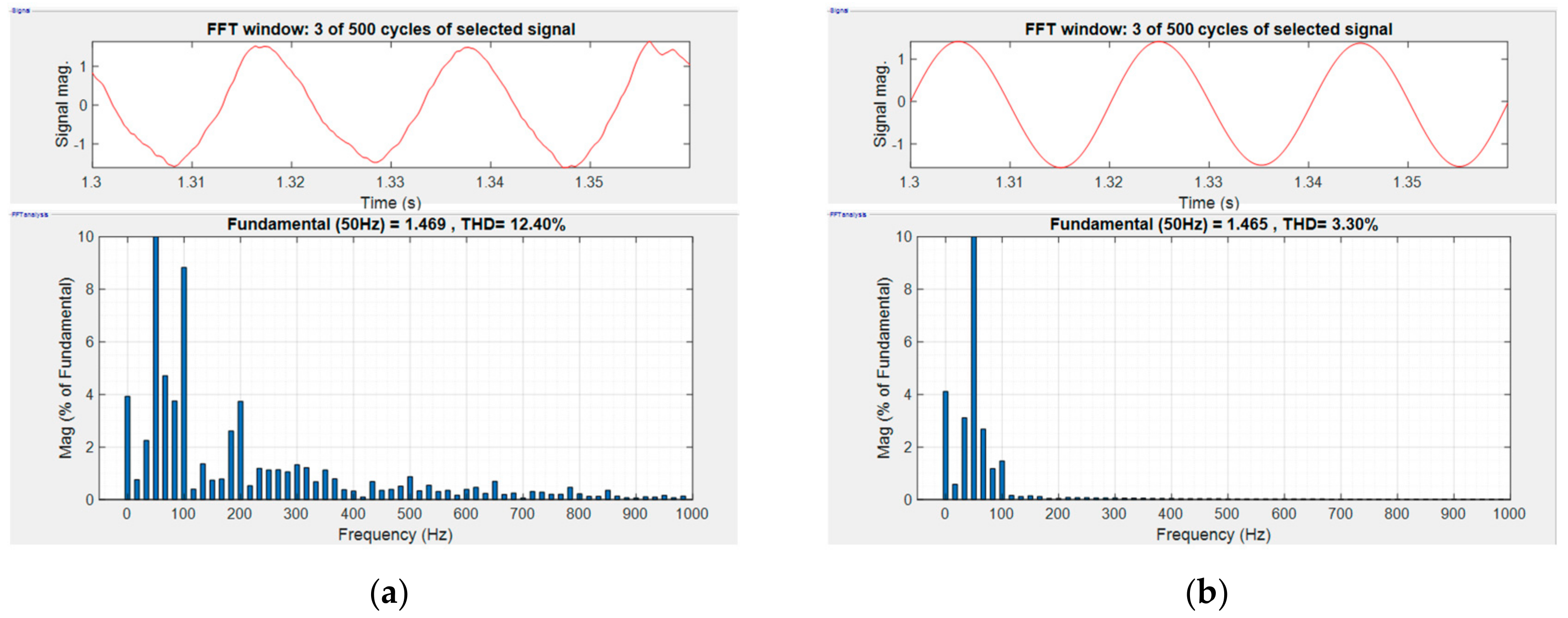
To achieve a deeper analysis of the discussed DTC techniques, the fast Fourier transform (FFT) was applied to the stator currents in order to determine the current total harmonic distortion (THD). The results are presented in Figure 20, and they show that the THD of the stator current was 12.40% and 3.30% for the 6-sectors and 12-sectors DTC, respectively.

Figure 20.
The FFT analysis of the phase-a stator current with (a) 6−sectors and (b) 12−sectors DTC control strategies.
It is clear from the analysis that the 12-sectors DTC had the best performance and the least number of ripples when compared to the conventional 6-sectors DTC. The considerable simplicity, reduction in torque and flux ripples, good dynamic responses, and low THD of the 12-sectors controller verify its effectiveness. Conversely, due to the increase in the size of the switching table, the computational complexity was prominent when using the 12-sectors control scheme.
6. Conclusions
The dynamic modeling and control approach of a WECS with a variable-speed direct-driven PMSG was presented in this paper. Through this, a new 12−sectors DTC control technique for PMSG-based wind turbines was proposed. The principle of the 6-sectors DTC control algorithm was first investigated, and, subsequently, the proposed DTC technique was presented in order to improve the performance and overcome the disadvantages of the conventional method. The simulations were carried out in the MATLAB/Simulink environment, and the characteristics of the PMSG for both the DTC algorithms were discussed and compared.
Compared to the conventional 6−sectors method, the proposed 12−sectors DTC showed more satisfactory performance with a considerable reduction in flux and torque ripples, good dynamic performance, low THD and, thus, the best output characteristics.
Future work can extend the current study by implementing the proposed control technique in an FPGA-based control system.
Funding
This research received no external funding.
Institutional Review Board Statement
Not applicable.
Informed Consent Statement
Not applicable.
Data Availability Statement
Not applicable.
Conflicts of Interest
The authors declare no conflict of interest.
References
- Rasul, M.G.; Azad, A.K.; Sharma, S.C. Clean Energy for Sustainable Development Comparisons and Contrasts of New Approaches; Academic Press is an imprint of Elsevier: Amsterdam, The Netherlands, 2017; ISBN 978-0-12-805423-9. [Google Scholar]
- Polinder, H.; van der Pijl, F.; de Vilder, G.-J.; Tavner, P.J. Comparison of Direct-Drive and Geared Generator Concepts for Wind Turbines. IEEE Trans. Energy Convers. 2006, 21, 725–733. [Google Scholar] [CrossRef] [Green Version]
- Wu, B.; Xu, D.; Ji, J.; Zhao, W.; Jiang, Q. Field-oriented control and direct torque control for a five-phase fault-tolerant flux-switching permanent-magnet motor. Chin. J. Electr. Eng. 2018, 4, 48–56. [Google Scholar] [CrossRef]
- Busca, C.; Stan, A.-I.; Stanciu, T.; Stroe, D.I. Control of Permanent Magnet Synchronous Generator for large wind turbines. In Proceedings of the 2010 IEEE International Symposium on Industrial Electronics (ISIE 2010), Bari, Italy, 4 July 2010–7 July 2010; pp. 3871–3876. [Google Scholar]
- Abosh, A.H.; Zhu, Z.Q.; Ren, Y. Reduction of Torque and Flux Ripples in Space Vector Modulation-Based Direct Torque Control of Asymmetric Permanent Magnet Synchronous Machine. IEEE Trans. Power Electron. 2017, 32, 2976–2986. [Google Scholar] [CrossRef]
- Kim, S.J.; Kim, J.-W.; Park, B.-G.; Lee, D.-H. A Novel Predictive Direct Torque Control Using an Optimized PWM Approach. IEEE Trans. Ind. Appl. 2021, 57, 2537–2546. [Google Scholar] [CrossRef]
- Guo, L.; Zhang, X.; Yang, S.; Xie, Z.; Wang, L.; Cao, R. Simplified model predictive direct torque control method without weighting factors for permanent magnet synchronous generator-based wind power system. IET Electr. Power Appl. 2017, 11, 793–804. [Google Scholar] [CrossRef]
- Preindl, M.; Bolognani, S. Model Predictive Direct Torque Control With Finite Control Set for PMSM Drive Systems, Part 1: Maximum Torque Per Ampere Operation. IEEE Trans. Ind. Inf. 2013, 9, 1912–1921. [Google Scholar] [CrossRef]
- Yaramasu, V.; Wu, B. Predictive Control of a Three-Level Boost Converter and an NPC Inverter for High-Power PMSG-Based Medium Voltage Wind Energy Conversion Systems. IEEE Trans. Power Electron. 2014, 29, 5308–5322. [Google Scholar] [CrossRef]
- Golnary, F.; Moradi, H. Dynamic modelling and design of various robust sliding mode controls for the wind turbine with estimation of wind speed. Appl. Math. Model. 2019, 65, 566–585. [Google Scholar] [CrossRef]
- Beltran, B.; Benbouzid, M.E.H.; Ahmed-Ali, T. Second-Order Sliding Mode Control of a Doubly Fed Induction Generator Driven Wind Turbine. IEEE Trans. Energy Convers. 2012, 27, 261–269. [Google Scholar] [CrossRef] [Green Version]
- Do, T.D. Disturbance Observer-Based Fuzzy SMC of WECSs Without Wind Speed Measurement. IEEE Access 2017, 5, 147–155. [Google Scholar] [CrossRef]
- Watil, A.; El Magri, A.; Raihani, A.; Lajouad, R.; Giri, F. Multi-objective output feedback control strategy for a variable speed wind energy conversion system. Int. J. Electr. Power Energy Syst. 2020, 121, 106081. [Google Scholar] [CrossRef]
- Errami, Y.; Ouassaid, M.; Maaroufi, M. A performance comparison of a nonlinear and a linear control for grid connected PMSG wind energy conversion system. Int. J. Electr. Power Energy Syst. 2015, 68, 180–194. [Google Scholar] [CrossRef]
- Zhang, Z.; Wang, F.; Si, G.; Kennel, R. Predictive encoderless control of back-to-back converter PMSG wind turbine systems with Extended Kalman Filter. In Proceedings of the 2016 IEEE 2nd Annual Southern Power Electronics Conference (SPEC), Auckland, New Zealand, 5 December 2016–8 December 2016; pp. 1–7. [Google Scholar]
- Mousa, H.H.; Youssef, A.-R.; Mohamed, E.E. Hybrid and adaptive sectors P&O MPPT algorithm based wind generation system. Renew. Energy 2020, 145, 1412–1429. [Google Scholar] [CrossRef]
- Shang, L.; Hu, J. Sliding-Mode-Based Direct Power Control of Grid-Connected Wind-Turbine-Driven Doubly Fed Induction Generators Under Unbalanced Grid Voltage Conditions. IEEE Trans. Energy Convers. 2012, 27, 362–373. [Google Scholar] [CrossRef]
- Toumi, I.; Meghni, B.; Hachana, O.; Azar, A.T.; Boulmaiz, A.; Humaidi, A.J.; Ibraheem, I.K.; Kamal, N.A.; Zhu, Q.; Fusco, G.; et al. Robust Variable-Step Perturb-and-Observe Sliding Mode Controller for Grid-Connected Wind-Energy-Conversion Systems. Entropy 2022, 24, 731. [Google Scholar] [CrossRef]
- Fateh, F.; White, W.N.; Gruenbacher, D. A Maximum Power Tracking Technique for Grid-Connected DFIG-Based Wind Turbines. IEEE J. Emerg. Sel. Top. Power Electron. 2015, 3, 957–966. [Google Scholar] [CrossRef]
- Abdellatif, W.S.E.; Hamada, A.M.; Abdelwahab, S.A.M. Wind speed estimation MPPT technique of DFIG-based wind turbines theoretical and experimental investigation. Electr Eng 2021, 103, 2769–2781. [Google Scholar] [CrossRef]
- Nasiri, M.; Milimonfared, J.; Fathi, S.H. A review of low-voltage ride-through enhancement methods for permanent magnet synchronous generator based wind turbines. Renew. Sustain. Energy Rev. 2015, 47, 399–415. [Google Scholar] [CrossRef]
- Ashourianjozdani, M.; Lopes, L.A.C.; Pillay, P. Power Electronic Converter Based PMSG Emulator: A Testbed for Renewable Energy Experiments. IEEE Trans. Ind. Applicat. 2018, 54, 3626–3636. [Google Scholar] [CrossRef]
- Prakash, M.; Joo, Y.-H. Fuzzy Event-triggered Control for Back to Back Converter involved PMSG-based Wind Turbine Systems. IEEE Trans. Fuzzy Syst. 2021, 30, 1409–1420. [Google Scholar] [CrossRef]
- Said-Romdhane, M.; Naouar, M.; Belkhodja, I.; Monmasson, E. An Improved LCL Filter Design in Order to Ensure Stability without Damping and Despite Large Grid Impedance Variations. Energies 2017, 10, 336. [Google Scholar] [CrossRef] [Green Version]
- Teodorescu, R.; Liserre, M.; Rodríguez, P. Grid Converters for Photovoltaic and Wind Power Systems. Wiley: Chichester, UK, 2011; ISBN 047066 7052. [Google Scholar]
- Reznik, A.; Simoes, M.G.; Al-Durra, A.; Muyeen, S.M. LCL Filter Design and Performance Analysis for Grid-Interconnected Systems. IEEE Trans. Ind. Appl. 2014, 50, 1225–1232. [Google Scholar] [CrossRef]
- Lu, M.; Al-Durra, A.; Muyeen, S.M.; Leng, S.; Loh, P.C.; Blaabjerg, F. Benchmarking of Stability and Robustness Against Grid Impedance Variation for LCL -Filtered Grid-Interfacing Inverters. IEEE Trans. Power Electron. 2018, 33, 9033–9046. [Google Scholar] [CrossRef] [Green Version]
- Sanatkar-Chayjani, M.; Monfared, M. Design of LCL and LLCL filters for single-phase grid connected converters. IET Power Electron. 2016, 9, 1971–1978. [Google Scholar] [CrossRef] [Green Version]
- Xue, C.; Zhou, D.; Li, Y. Hybrid Model Predictive Current and Voltage Control for LCL-Filtered Grid-Connected Inverter. IEEE J. Emerg. Sel. Top. Power Electron. 2021, 9, 5747–5760. [Google Scholar] [CrossRef]
- Rockhill, A.A.; Liserre, M.; Teodorescu, R.; Rodriguez, P. Grid-Filter Design for a Multimegawatt Medium-Voltage Voltage-Source Inverter. IEEE Trans. Ind. Electron. 2011, 58, 1205–1217. [Google Scholar] [CrossRef] [Green Version]
- Liserre, M.; Blaabjerg, F.; Hansen, S. Design and Control of an LCL-Filter-Based Three-Phase Active Rectifier. IEEE Trans. Ind. Appl. 2005, 41, 1281–1291. [Google Scholar] [CrossRef]
- Zhan, P.; Lin, W.; Wen, J.; Yao, M.; Li, N. Design of LCL filters for the back-to-back converter in a Doubly Fed Induction Generator. In Proceedings of the IEEE PES Innovative Smart Grid Technologies—Asia (ISGT Asia), Tianjin, China, 21 May 2012–24 May 2012; pp. 1–2. [Google Scholar]
- Bansal, R.C. Handbook of Distributed Generation: Electric Power Technologies, Economics and Environmental Impacts; Ramesh, B., Ed.; Springer: Cham, Switzerland, 2017; ISBN 9783319513430. [Google Scholar]
- Xu, D.a.; Xu, D.; Blaabjerg, F.; Chen, W.; Zhu, N. Modelling and Control of Doubly Fed Induction Generator Wind Power System under Non-Ideal Grid, 1st ed.; Wiley-IEEE Press: Hoboken, NJ, USA, 2016; ISBN 978-1-119-17208-6. [Google Scholar]
- Al-Quteimat, A. Control Layout of Doubly Fed Induction Generator with Respect to Low Voltage Ride through for Wind Energy Conversion System. 2018. Available online: https://depositonce.tu-berlin.de//handle/11303/8209 (accessed on 1 February 2022). [CrossRef]
- Xu, Z.; Rahman, M.F. Direct torque and flux regulation of an IPM synchronous motor drive using variable structure control approach. In Proceedings of the IECON 2004, 30th Annual Conference of the IEEE Industrial Electronics Society, Busan, South Korea, 2–6 November 2004; IEEE: Piscataway, NJ, USA, 2004; pp. 2487–2498. [Google Scholar]
- Rahman, M.F.; Zhong, L.; Lim, K.W. A direct torque-controlled interior permanent magnet synchronous motor drive incorporating field weakening. IEEE Trans. Ind. Appl. 1998, 34, 1246–1253. [Google Scholar] [CrossRef]
- Al-Quteimat, A.; Roccaforte, A.; Schafer, U. Performance improvement of direct torque control for doubly fed induction generator with 12 sector methodology. In Proceedings of the 2016 IEEE International Conference on Renewable Energy Research and Applications (ICRERA), Birmingham, UK, 20–23 November 2016; pp. 242–246. [Google Scholar] [CrossRef]


Publisher’s Note: MDPI stays neutral with regard to jurisdictional claims in published maps and institutional affiliations. |
© 2022 by the author. Licensee MDPI, Basel, Switzerland. This article is an open access article distributed under the terms and conditions of the Creative Commons Attribution (CC BY) license (https://creativecommons.org/licenses/by/4.0/).