Article

Application of Simulation Analysis for Thermal Management Technology on Main Parts of Pouch Cells

College of Automotive and Rail, Anhui Technical College of Mechanical and Electrical Engineering, Wuhu 241002, China
*
Author to whom correspondence should be addressed.
World Electr. Veh. J. 2023, 14(5), 124; https://doi.org/10.3390/wevj14050124
Submission received: 23 March 2023 / Revised: 25 April 2023 / Accepted: 9 May 2023 / Published: 11 May 2023

Abstract

:
The technology of large surface thermal management of pouch cells was studied and discussed by means of simulation. With thermal management, two cells are managed by a single cold plate. First, the pressure drop of the cold plate was simulated and the velocity distribution of the flow field was observed. The cooling performance of the cold plate to the cell was then studied, and the low-temperature heating ability of the cold plate to the cell was analyzed. Through analysis, it can be concluded that large surface thermal management technology can effectively and quickly control the temperature rise of the cell when the cell is charging and discharging and the temperature difference is less than 5 °C. Finally, a control strategy for low-temperature heating of the cell by the cold plate was proposed.

1. Introduction

Exhaust emissions from fuel vehicles are one of the main sources of air pollution [1]. Compared with traditional fuel vehicles, new energy vehicles can effectively reduce the emissions of vehicle exhaust. Therefore, new energy vehicles have received strong support from the government, they have been rapidly developed, and ownership has been rapidly increased. At the present stage, new energy vehicles mostly use lithium-ion batteries as their driving power. However, lithium-ion batteries have their own suitable temperature range, and low battery temperature will make the lithium battery activity decrease. Lithium-ion batteries generate a great deal of heat in the process of high-rate charging and discharging, and high temperature will cause lithium-ion batteries to produce gas, life decay, or even cause thermal runaway. Lithium-ion batteries also have more stringent requirements for temperature difference, and unbalanced temperature distribution among single cells can seriously affect the service life and power performance of the battery pack. Thermal management of lithium-ion batteries has become a hot spot for research and application. Engineering simulations are more often used for research. Computer engineering simulation is to determine the distribution of the battery under different working conditions by establishing a mathematical physical relationship model that determines the liquid flow condition, heat transfer, and each physical quantity and then gives a qualitative and quantitative description of the temperature characteristics of the battery system. Computer simulation has many advantages, such as flexibility, speed, and cost saving.
Lang et al. [2] studied the low-temperature performance of ternary material lithium-ion batteries, and the results showed that when the ambient temperature is lower than 0 °C, the end voltage, internal resistance, capacity, and other performance of ternary material lithium-ion battery will be decreased to different degrees. When the ambient temperature is lower than −10 °C, the charging and discharging voltage curves all show non-linear changes, and the internal resistance changes are more drastic, which seriously affects the battery life. When the ambient temperature is lower than −20 °C, the battery cannot be discharged at a large rate. When the ambient temperature is below −30 °C, the large and small multiplier discharge cannot be carried out, and the charging capacity drops significantly. Deng et al. [3] reviewed the latest research results on battery liquid cooling systems in terms of coolant performance, liquid cooling system classification, and battery pack design. In the work of Li et al. [4], a battery thermal management system design process was proposed based on the battery performance model. The experimental analysis of the lithium-ion battery temperature rise, low-temperature performance, and the adaptability of the battery performance model was carried out, and a battery thermal analysis modeling method was proposed using the battery thermoelectric coupling and heat conduction theory. Deng et al. [5] proposed a multi-objective optimization design method for a double-layer reversible cooling plate for lithium-ion batteries. Zhao et al. [6] designed a new hybrid vehicle battery thermal management system using the air conditioning system and engine exhaust system to regulate the temperature of the battery pack. The structure of the battery pack was designed by joint optimization using FLUENT simulation software and DesignXplorer module. Du et al. [7] used the CFD solver to simulate the liquid-cooled heat dissipation model of an electric vehicle lithium-ion battery pack to analyze the effects of the cold plate structure, the coolant flow rate, and the choice of coolant on the heat dissipation effect of the liquid-cooled heat dissipation structure. The results showed that the cold plate structure of a spiral channel can make the cold plate temperature more uniform, but the velocity flow line inside the tube is not stable; the larger the flow rate of coolant, the lower the maximum temperature of the battery pack, and the larger the temperature difference. Wang et al. [8] introduced and analyzed the research progress of phase change materials in the thermal management of power batteries in recent years, especially introducing the research progress of high thermal conductivity phase change materials and their practical application effects and making an outlook on the future development direction in this field. Lian et al. [9] established the thermal structure model of a three-dimensional power lithium-ion battery module based on the COMSOL Multiphysics simulation platform and the corresponding thermal modeling theory of lithium-ion battery was verified and studied under a fixed 5C multiplier discharge condition. Li et al. [10] used CFD software to study the thermal effects of serial air-cooled 18,650 cylindrical Li-ion power packs. The effects of cell arrangement, cell spacing, and air inlet velocity on the temperature distribution of the pack were investigated, and the simulation model was validated by designing experiments. Sheng et al. [11] developed a new serpentine channel liquid cooling plate with dual inlets and dual outlets. By simplifying the cell module model and using FloEFD software for numerical analysis, the effects of flow direction, flow rate, and cooling plate channel width on the cell temperature distribution under different operating conditions were investigated, and the power consumption ratio was defined as a factorless number to analyze the hydrodynamic performance of the developed cooling plate. The results show that the inlet and outlet locations, as well as the flow direction, have a significant effect on the cell temperature distribution and the power consumption ratio of the cooling plate. Increasing the fluid flow rate significantly reduces the maximum temperature rise of the cell assembly but has little effect on the temperature distribution. In the work of Lai et al. [12], a compact and lightweight liquid-cooled thermal management system was proposed to control the maximum temperature and temperature difference of a lithium-ion power battery pack. In this liquid-cooled solution, a thermally conductive structure (TCS) with three curved contact surfaces was developed to cool the cylindrical cells. The effects of mass flow rate, inner diameter, contact surface height, and contact surface angle on the performance of the TCS were investigated by numerical simulations. Liu et al. [13] analyzed the working structure, operating principle, and heat production of lithium-ion batteries, studied the heat transfer theory of lithium-ion batteries, and established the thermal model of lithium-ion batteries. The heat source UDF of the battery monomer is written in Fluent to illustrate that the heat generation rate of the battery shows dynamic changes. A new thermal management system based on phase change material was proposed for the power battery pack. Xu et al. [14] conducted an experimental study on the liquid cooling system of electric vehicles using the cold plate liquid cooling method to analyze the effects of different water cooling plate flow diameters, liquid inlet flow, and ambient temperature on its thermal performance. Wang et al. [15] used the standard k-ε turbulence model and D-O radiation model to numerically simulate the flow and temperature fields in the liquid-cooled battery module of electric vehicles according to the heat generation characteristics of lithium batteries. Based on a systematic analysis of the battery pack heat dissipation system structure and the fluid dynamics theory, the work of Xue [16] showed the liquid-cooled battery pack heat dissipation simulation was revealed by ANSYS software The temperature field distribution of the battery pack during the charging and discharging process was likewise clearly understood, and the battery pack heat dissipation structure could be optimized on this basis to improve the performance of the power battery pack. Lv et al. [17] used a lithium iron phosphate LiFePO_4 battery as the research object to measure the heating temperature of battery packs with different cell numbers and to study the thermal effect law combined with the analysis of the cooling effect of different liquid cooling systems. The design idea of a new integral cooling plate was proposed, and a conceptual design diagram was drawn. Deng et al. [18] established the thermal model of lithium batteries and analyzed the heat generation of lithium batteries at different multiplier discharges. The thermal design of the Li-ion battery pack was carried out under the liquid cooling method to simulate the heat dissipation performance of the heat sink under the change of fluid temperature and flow rate when the battery pack is discharged. The simulation results show that liquid cooling can effectively reduce the temperature of the battery pack so that the temperature uniformity between the cells is good, but the temperature difference between the inside and outside of a single cell is relatively large when discharging at a large multiplier. By changing the inlet mass flow rate and optimizing the design under different working conditions, the temperature difference between the inside and outside of the cell can be reduced so the cell can work in a reasonable temperature range.
Li-ion battery thermal management methods include natural cooling, air cooling, liquid cooling, direct refrigerant cooling, and phase change cooling. Compared with natural cooling and air cooling, liquid cooling has higher cooling efficiency and better temperature uniformity control. Refrigerant direct cooling is used in foreign high-end models, its control is more complex, and the technology is still immature for domestic use, which needs to be further studied. Phase change cooling is more difficult to apply to power lithium-ion battery packs due to space constraints. Now the market provides more active cooling methods for liquid cooling. The current lithium-ion battery liquid cooling is more often used in the bottom of the battery module arrangement of the large cold plate through the module of the aluminum plate to export heat to the cold plate; thermal path thermal resistance is therefore high, so the cell temperature control response is slow. The cold plate introduced in this paper is in contact with the large surface of the pouch cell, thus reducing the thermal resistance and facilitating heat export.
In this paper, a systematic study is conducted for the thermal management method of the pouch cell body. Simulation is carried out by Fluent software to study the flow resistance and flow rate distribution of this cold plate under different flow rates. In addition, the temperature distribution of the battery and antifreeze under different operating conditions is analyzed by coupling the flow field and thermal field. Finally, the low-temperature heating process of the battery under this thermal management method is simulated and discussed.

2. Mathematical Models and Boundary Conditions

2.1. Geometric Models

Calculation formula of thermal resistance:
R = l λ · A
where R is the thermal resistance; l is the heat transfer spacing; A is the heat transfer area; and λ is the thermal conductivity of the heat transfer substance.
From Equation (1), it can be seen that increasing the heat transfer area is an effective way to reduce thermal resistance and increase heat transfer. In this paper, the large surface contact method is chosen for the thermal management of the pouch cell. The cold plate model used in this study is shown in Figure 1a. The thermal management of two cells is carried out by one cold plate, and the specific installation is shown in Figure 1b; each cold plate is connected in parallel.

2.2. Mathematical Models

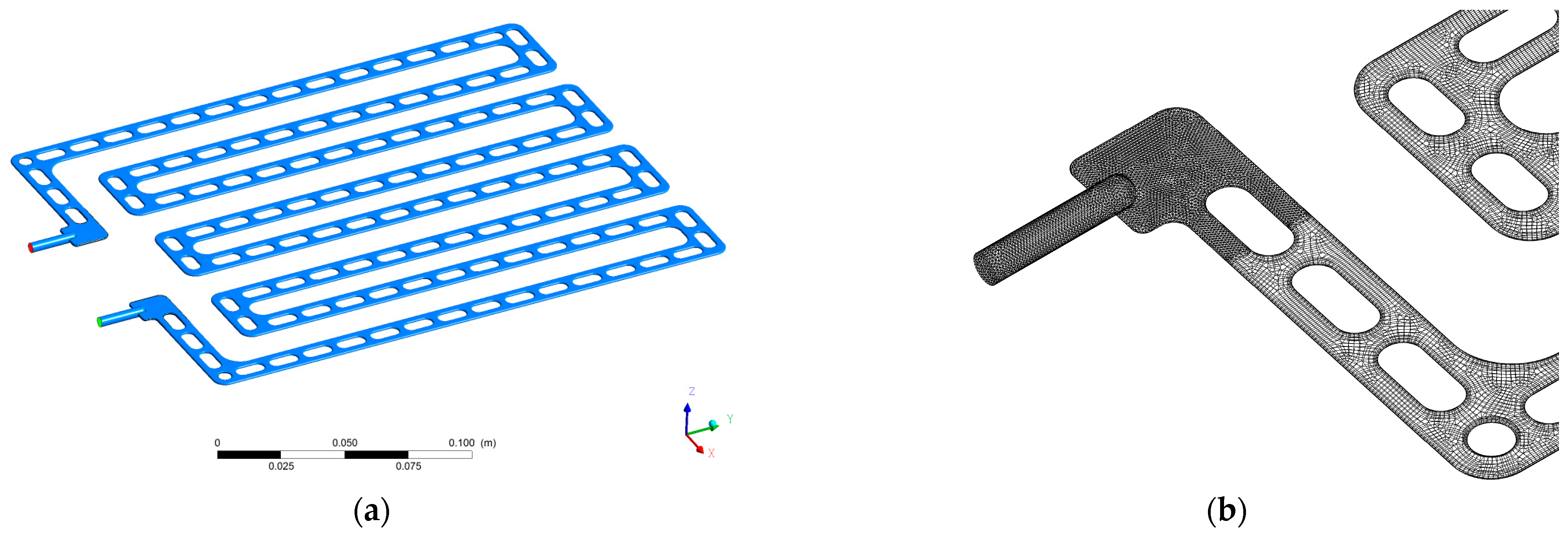
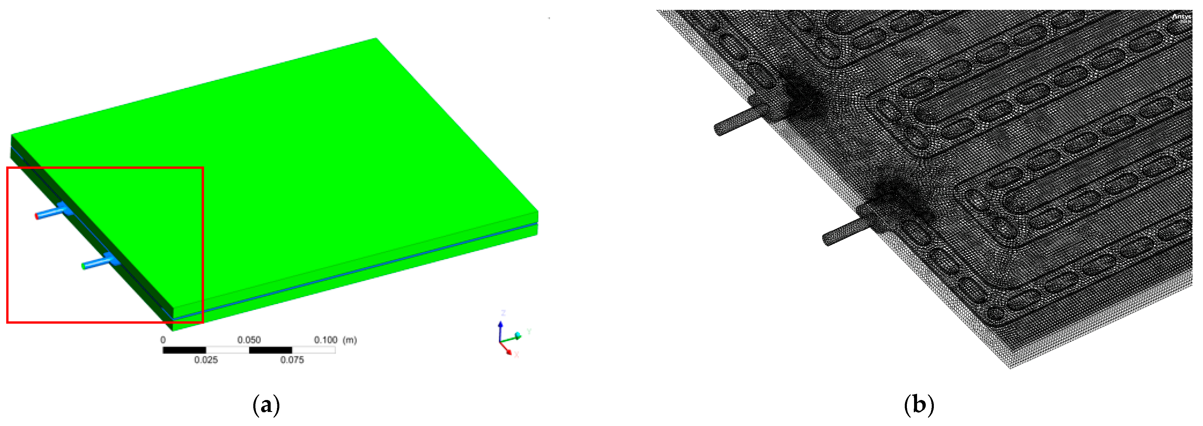
The study focuses on two main aspects: the flow field inside the cold plate and the temperature field of the cell. In the flow field part, the flow channel model is created and gridded according to the geometric model of the cold plate. Due to the complex flow channel entrance and exit, the local grid diagram is divided into tetrahedral grids, the other area grid is divided into hexahedral grids, and the total number of grids is 372,311, as shown in Figure 2. For the temperature field, a mathematical model of a single cold plate cooling two cells is created and gridded. Due to the complex flow channel at the entrance and exit, the local area grid is divided into tetrahedral grids, the other area grid is divided into hexahedral grids, and the cell is a hexahedral grid, The total number of grids is 675,887, as shown in Figure 3. It is verified that there is basically no difference in simulation results when the above grid quantity is increased by 10 times, so the grid size is reasonable.

2.3. Basic Control Equations

After calculating the Reynolds number, the flow field inside the cold plate is laminar flow, and the continuity and momentum equations need to be used in the calculation. The energy equation is used for the heat transfer [19].
(1)
Reynolds number
The Reynolds number formula is as follows. In this study, the maximum flow rate is 0.2 L/min, the inlet diameter is 4 mm, and the cross-sectional area is 12.6 mm2. The Reynolds number is calculated to be 2.98, which is less than 2300, so it is a laminar flow state.
R e = ρ V l μ
where ρ is density, kg/m3; μ is viscosity, Pa·s; V is characteristic velocity, m/s; and l is characteristic length, m.
(2)
Continuity equation
The continuity equation is also known as the mass conservation equation, and any problem of flow must satisfy the law of mass conservation [20]. The differential equation of continuity for a fluid is as follows:
ρ t + ( ρ V x ) x + ( ρ V y ) y + ( ρ V z ) z = 0
where V i is the velocity vector, m/s; ρ is the density, kg/m3; t is the time, s.
(3)
Momentum equation
The essence of the momentum equation is to satisfy Newton’s second law [21]. The differential equation of motion of the fluid is given here:
ρ V i t + ( ρ V x V i ) x + ( ρ V y V i ) y + ( ρ V z V i ) z = ρ g i P i + R i + x ( μ e V i x ) + y ( μ e V i y ) + z ( μ e V i z )
where g i is the component of gravitational acceleration in direction i, m/s2; μ e is the effective viscosity, Pa·s; P is the pressure, Pa; R i is the distributed resistance; i = x , y , z .
(4)
Energy equation
The essence of the law of conservation of energy is the first law of thermodynamics, which must be satisfied by a flow system containing heat exchange [22]. The differential equation of energy for its fluid follows
t ( ρ E ) + [ u ( ρ E + ρ ) ] = [ k d f f T j h j J j + ( τ e f f u ) ] + S h
where E is the total energy of the fluid as a microcluster, J/kg; h is the enthalpy, J/kg; hj is the enthalpy of component j, J/kg; k d f f is the effective heat transfer coefficient, W/(m·K); Jj is the diffusion flux of component j; and Sh is the volumetric heat source term that includes the heat of chemical reaction, as well as others defined by the user.

2.4. Boundary Conditions and Material Properties

Cold plate inlet: In order to analyze the flow resistance and core temperature distribution of the cold plate under different flow rates, the inlet flow rate is set to 0.05 L/min, 0.1 L/min, 0.15 L/min, and 0.2 L/min with inlet temperature 5 °C, 25 °C. The cold plate outlet is set as pressure outlet, and static pressure is 0 Pa. Core heat generation is set at 5.4 W according to the core heat generation rate at 1 C charging. Wall heat dissipation: the large surface of contact between the core and cold plate is set according to normal heat conduction, the contact surface between adjacent cores is set as adiabatic condition, and other exposed surfaces of the core are set as convection and radiation heat exchange with the environment. The properties of each material are shown in Table 1.

3. Results Analysis

3.1. Flow Field Simulation Analysis

The flow resistance must be considered comprehensively in the cold plate design process, which is related to the flow rate selection and pump selection. In general, the normal temperature flow resistance needs to be controlled below 50 kPa. This paper first analyzes the room temperature flow resistance of the cold plate at different flow rates, as shown in Figure 4. It can be seen that the flow resistance increases with the increase of flow rate, showing parabolic growth. The following equation can be obtained by fitting the curve:
y = 150 x 2 + 217.1 x 0.025
The above Formula (6) conforms to the law of change of flow resistance, which can be divided into two aspects: along-range head loss and local head loss.
Δ P f = λ l d ρ u 2 2
where λ is the friction factor, unitless; l is the length of the straight pipe, m; d is the diameter of the straight pipe, m; u is the flow rate of fluid in the pipe, m/s.
Formula (7) is known as the Fanning formula. The general formula for calculating the head loss along a circular straight pipe flow for incompressible fluid steady flow. The local head loss is calculated using the following equation.
h m = ς u 2 2 g
where ς is the local resistance coefficient, unitless.
Therefore, the flow resistance is a quadratic function of the flow velocity in the absence of a change in the flow state.
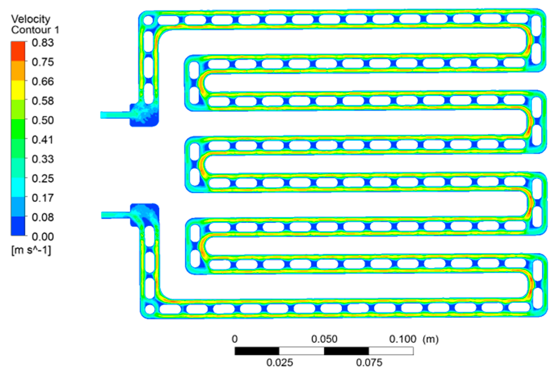
Figure 5 shows the flow rate distribution in the cold plate at a flow rate of 0.15 L/min. It can be seen that there is no large continuous flow dead zone in the flow process. There are only some dead zones at the corners of the entrance and exit and in the area between the islands of reinforcement in the flow channel. Because the cold plate material is aluminum alloy, it has good thermal conductivity and temperature equalization, which can transfer the heat from the dead zone to the surrounding antifreeze quickly. Therefore, the impact of the dead zone on the thermal conductivity of the cold plate can be ignored.

3.2. Simulation Analysis of Cooling of Electric Cell by Cold Plate

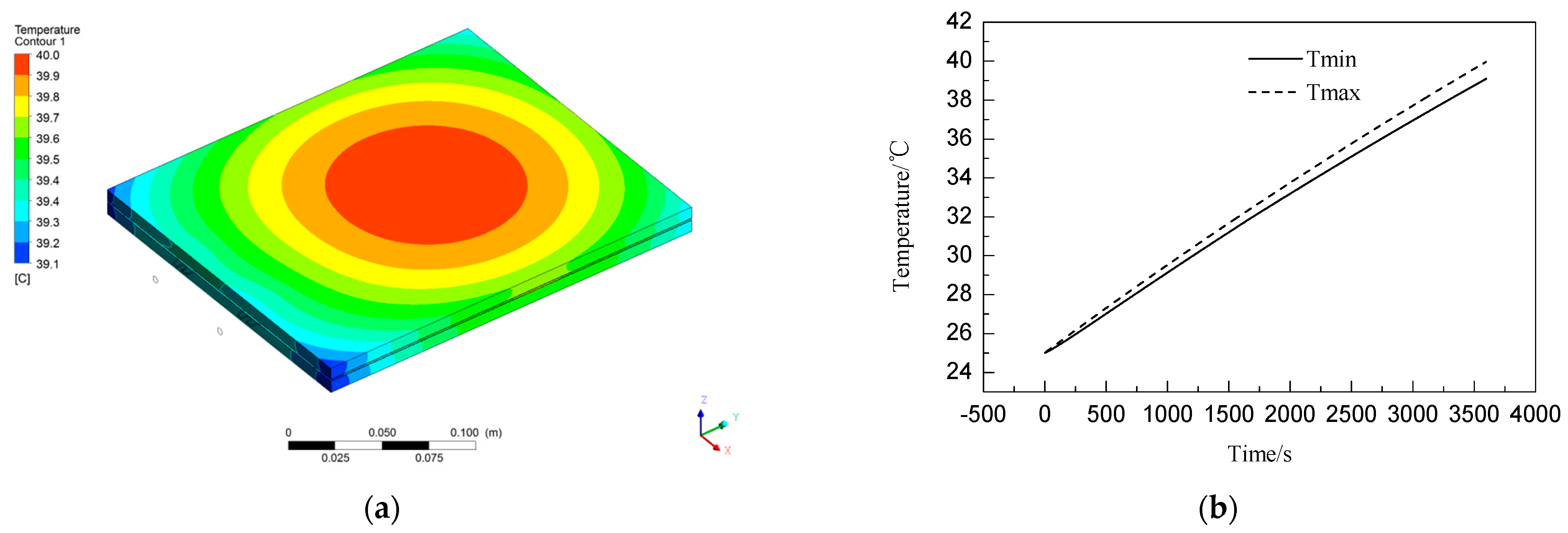
In the cooling simulation of the cold plate on the cell, for comparative analysis, the simulation is first performed for the case of antifreeze flow rate of 0 L/min. The initial ambient and core temperature is 25 °C, the core heat production rate is 5.4 W, and the time is 3600 s. The final core temperature distribution and the core temperature change curve are shown in Figure 6. After 1 h of 1C charging, the core rises from 25 °C to 40 °C with a temperature rise of 15 °C. Due to the heat dissipation from the edge of the core to the environment, the highest temperature position is located in the middle of the core and the lowest position is located at the corners of the core, with a maximum temperature difference of 0.9 °C. The higher the temperature, the more heat is transferred from the edge of the core to the outside through convection and radiation, and the temperature rise rate gradually decreases.
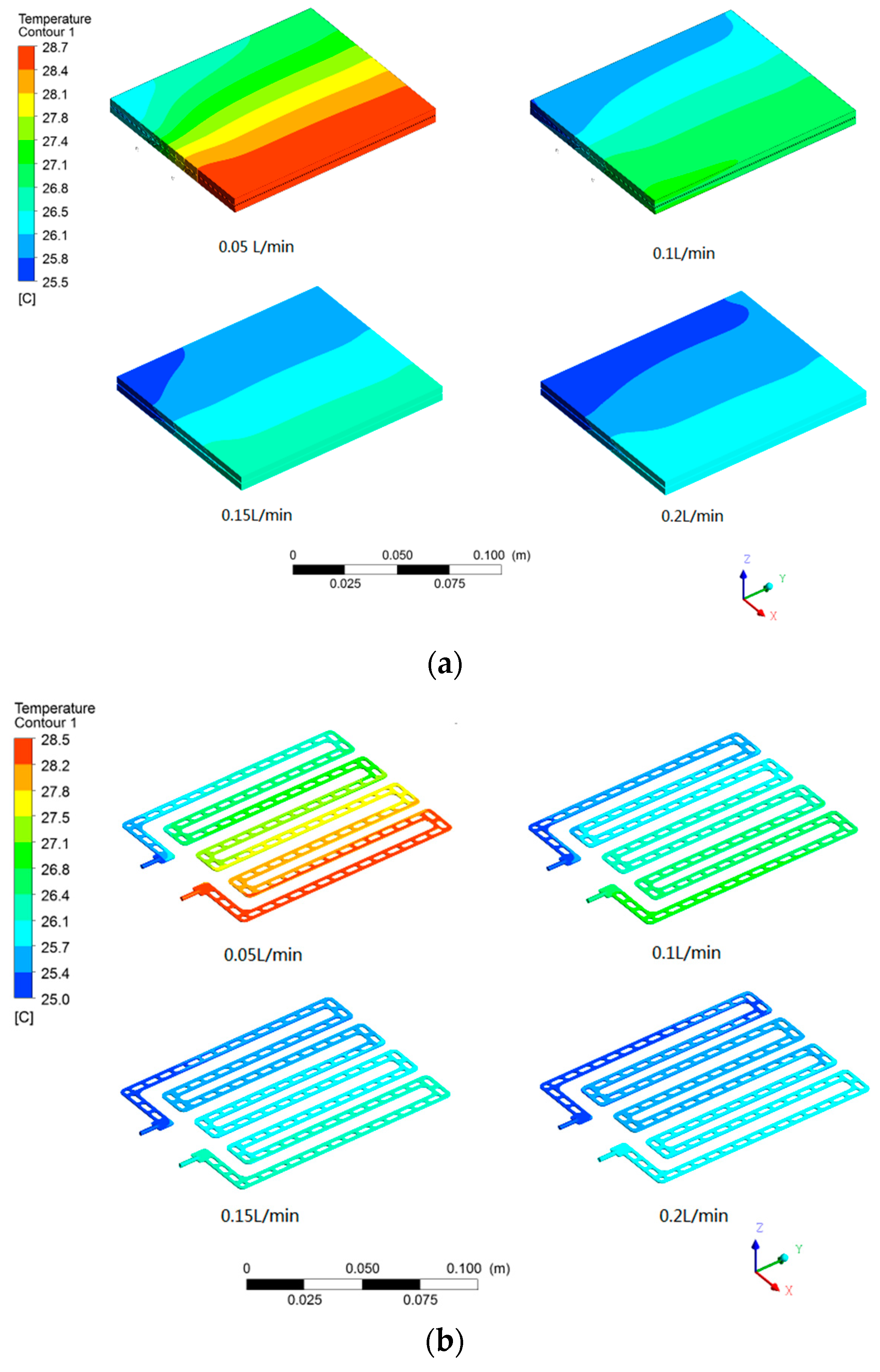
Next, simulations are performed for the cases of antifreeze flow rate of 0.05 L/min, 0.1 L/min, 0.15 L/min, and 0.2 L/min, respectively. The temperature distribution of the core is shown in Figure 7a, which shows the initial ambient and core temperature of 25 °C, the heat generation rate of the core is 5.4 W, and the time is 3600 s. It can be seen that the core temperature decreases significantly with respect to the case where the flow rate of antifreeze is 0 L/min, and the larger the flow rate, the more the temperature decreases. The larger the flow rate, the smaller the temperature difference between the cold plate entrance and exit, as shown in Figure 7b. This is because the heat exchange between the core and the environment is much lower than the heat exchange between the core and the antifreeze, and the approximation can be considered that all the heat generated by the core is taken away by the antifreeze. Finally, the core temperature has reached a stable level and will not change anymore. The temperature difference between the cold plate entrance and exit in this case is in accordance with the following equation:
d P d t = c d q d t Δ T
That is
P = c q Δ T
where P is the heat producing power of the core, W; c is the specific heat, J/(kg·K); q is the flow rate, kg/s.
For this core cooling process, P and c are constant values, so the higher the flow rate q, the lower the temperature difference between the inlet and outlet. The temperature of antifreeze gradually increases during the flow from the inlet into the cold plate to the outlet side. The temperature in homogeneity of antifreeze causes the uneven temperature distribution of the core, and the temperature near the inlet side is smaller than the temperature on the outlet side. The greater the flow rate, the smaller the temperature rise of antifreeze, and the temperature difference of the core will be reduced.
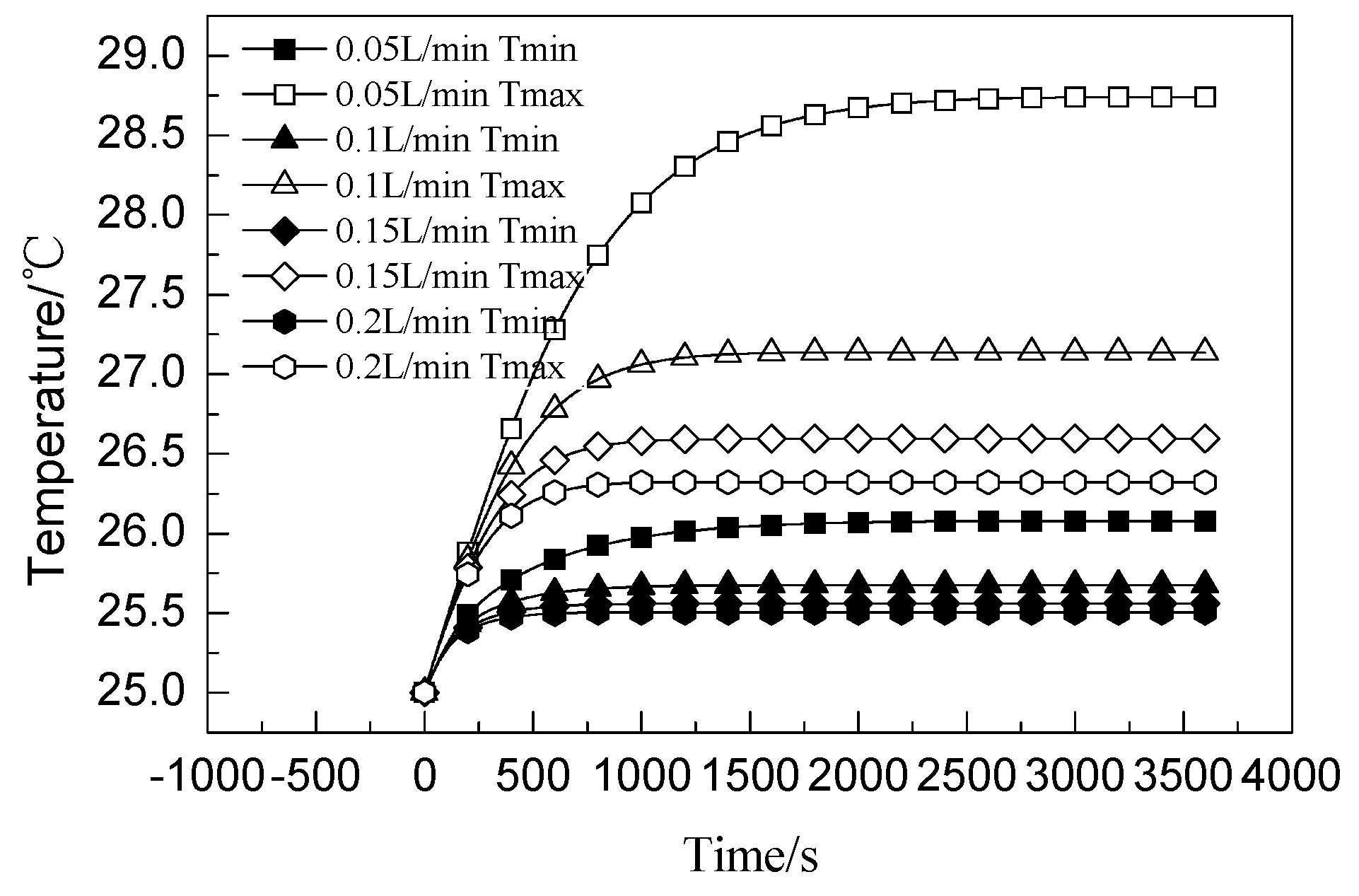
Figure 8 shows the temperature change curve of the core at different flow rates. The thermal resistance between the core and the cold plate is a constant value, and the thermal resistance equation is shown as follows:
R = Δ T P
where P is heat flux, W.
Therefore, the heat taken away by liquid cooling is proportional to the temperature difference. At the beginning of the test, due to the small temperature difference between the core and the cold plate, the heat taken away by the liquid cooling is smaller than the heat produced by the core, and the temperature of the core gradually increases. When the temperature difference between the core and the cold plate increases, the heat taken away by the cold plate is the same as the heat produced by the core, and the temperature reaches stability and no longer changes. The higher the flow rate, the slower the temperature rise rate of the core and the lower the maximum temperature. The reason for this trend is that the higher the flow rate, the slower the temperature rise of the antifreeze, which increases the temperature difference between the core and the antifreeze; the higher the flow rate, the higher the convective heat transfer coefficient and the corresponding lower the thermal resistance. It can be seen that the temperature of the core is effectively controlled, and the temperature difference is controlled within 3 °C.

3.3. Simulation Analysis of the Heating of the Core by the Cold Plate

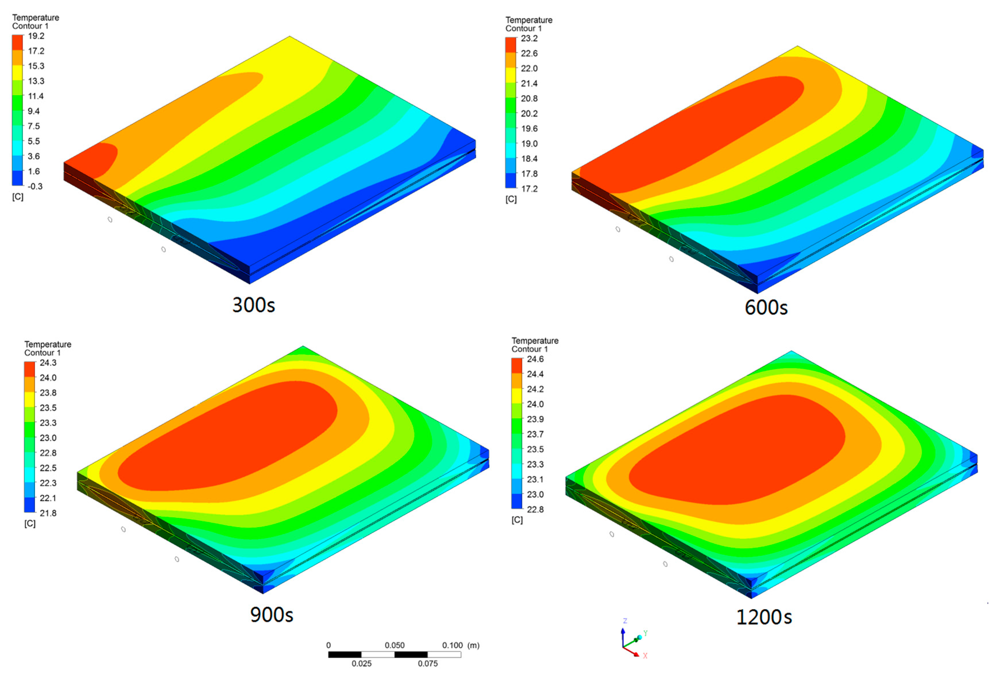
Thermal management is to achieve both cooling of the cell during charging and discharging to maintain the optimal operating temperature of the cell and heating in a low-temperature environment so the temperature of the cell is above 0 °C during charging. In this paper, the simulation analysis is also carried out for the low temperature heating of the cell by the cold plate. The simulation conditions are ambient and initial cell temperature of 30 °C; antifreeze temperature of 25 °C and 5 °C; flow rates of 0.05 L/min, 0.1 L/min, 0.15 L/min, and 0.2 L/min respectively. Figure 9 shows the variation of cell temperature with time for an antifreeze temperature of 25 °C and a flow rate of 0.2 L/min. The core starts to warm up from the inlet side, and the outlet side has the lowest temperature. The temperature difference is large at 300s, which is due to the large temperature difference between the antifreeze and the core, reaching 55 °C. In the initial stage of the test, heat is absorbed by the core at the inlet, and the rapid drop of the antifreeze temperature is not enough to warm up the area afterward. However, as the temperature of the core at the entrance rises over time, the heat absorbed at this location decreases. There can be enough heat to warm up the subsequent location, so the temperature of the low-temperature side rises, and the temperature difference gradually decreases.
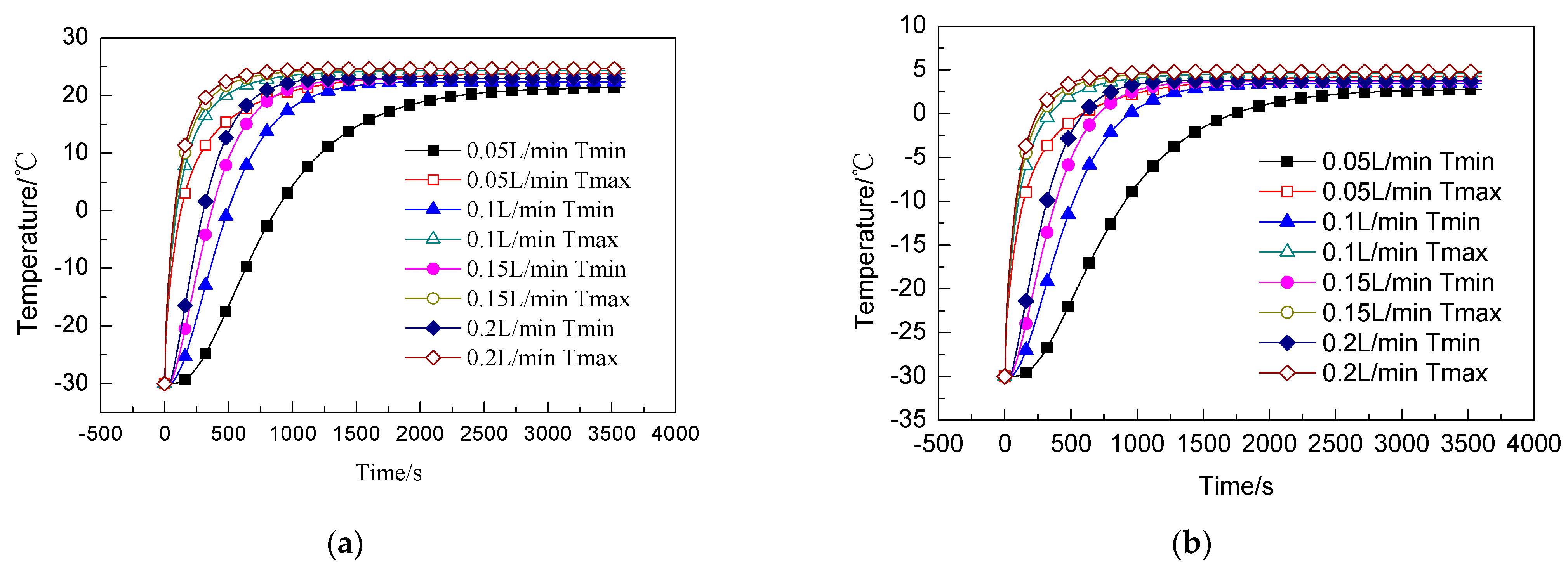
Figure 10 shows the change of core temperature over time for different antifreeze temperature and different flow rates. Figure 11 shows the change curve of core temperature differences corresponding to Figure 10. Because the core temperature gradually increases, the higher the flow rate, the higher the heat provided to the core per unit time, and the faster the temperature rise rate of the core, though all will be closer and closer to the temperature of the antifreeze. The higher the temperature of antifreeze, the greater the temperature difference between the core and the cold plate, and the more heat transfer, resulting in a faster temperature rise of the core but the greater the temperature difference. The core temperature difference rises first and then decreases. Under the same conditions of antifreeze temperature, the smaller the flow rate, the larger the temperature difference.
It is assumed that the minimum temperature of the core rises above 0 °C when the heating of the core is stopped, and the charging starts. After analysis, the maximum temperature difference of a single cell when heating is stopped at antifreeze temperature of 25 °C is 20.0 °C (0.05 L/min), 20.3 °C (0.1 L/min), 19.7 °C (0.15 L/min), and 19.1 °C (0.2 L/min) respectively. When the heating condition is carried out with antifreeze temperature of 5 °C, the maximum temperature difference of individual cells when heating is stopped is 3.8 °C (0.05 L/min), 4.0 °C (0.1 L/min), 4.0 °C (0.15 L/min), and 3.9 °C (0.2 L/min), respectively. Therefore, this heating method should set the temperature of the antifreeze 5 °C higher than the minimum temperature allowed for charging (assuming the design target temperature difference is within 5 °C) as a reference when setting the heating strategy.

4. Conclusions

In this paper, the large surface thermal management technology of pouch cells is investigated mainly through simulation methods. The following conclusions are drawn.
(1)
For the cold plate used in this study, the flow resistance is a quadratic function of the flow rate, y = 150 x 2 + 217.1 x 0.025 . Under the condition that the flow rate is less than 0.2 L/min, the general design requirement of flow resistance < 50 kPa is satisfied.
(2)
The large surface thermal management technology of pouch cells can effectively and quickly control the temperature rise of the core when the core is charged and discharged. The greater the flow rate, the slower the temperature rise rate of the core, and the lower the maximum temperature. The temperature difference of the core is below 3 °C.
(3)
When heating the core at low temperature, the temperature of the core gradually increases. The result is that the higher the flow rate, the faster the temperature rise rate of the core that finally reaches close to the temperature of the antifreeze. The higher the temperature of the antifreeze, the faster the temperature rise of the core, but the greater the temperature difference. The temperature difference of the core rises first and then decreases. Under the same condition of antifreeze temperature, the smaller the flow rate, the larger the temperature difference.
(4)
When setting the heating strategy for the low temperature heating method in this study, the antifreeze temperature should be set with a design target temperature difference higher than the minimum temperature allowed for charging as a reference.

Author Contributions

Conceptualization, B.W. and F.D.; data curation, B.W.; funding acquisition, B.W. and Q.Z.; methodology, B.W. and F.D.; project administration, M.L.; supervision, M.L.; visualization, M.T.; writing original draft preparation, B.W.; writing—review and editing, B.W. and F.D. All authors will be informed about each step of manuscript processing including submission, revision, revision reminder, etc. All authors have read and agreed to the published version of the manuscript.

Funding

The authors would like to thank the financial supports for the key natural science research projects of colleges and universities in the Anhui Province, Nos. KJ2020A1101, KJ2020A1116 and 2022AH052354, and Anhui Province New Energy Vehicle Technology Professional Teaching Team Project, No.2021jxtd064.

Data Availability Statement

Not applicable.

Conflicts of Interest

The authors declare no conflict of interest.

References

  1. Cheng, Y.B.; Jin, Y.L.; Liu, Y.C. National institute for environmental health and related product safety. J. Hyg. Res. 2003, 32, 504–507. (In Chinese) [Google Scholar]
  2. Lang, C.Y.; Luo, B. Research on cryogenic properties of NCM batteries. Mach. Electron. 2016, 34, 7–12. (In Chinese) [Google Scholar]
  3. Deng, Y.W.; Feng, C.L.; Jiaqiang, E.; Zhu, H.; Chen, J.; Wen, M.; Yin, H. Effects of different coolants and cooling strategies on the cooling performance of the power lithium ion battery system: A review. Appl. Therm. Eng. 2018, 142, 10–29. [Google Scholar] [CrossRef]
  4. Li, J.Q.; Wu, P.E.; Zhang, C.N. Study and implementation of thermal management technology for the power batteries of electric vehicles. Automot. Eng. 2016, 38, 22–27+35. (In Chinese) [Google Scholar]
  5. Deng, T.; Ran, Y.; Yin, Y.L.; Chen, X.; Liu, P. Multi-objective optimization design of double-layered reverting cooling plate for lithium-ion batteries. Int. J. Heat Mass Transf. 2019, 143, 118580. [Google Scholar] [CrossRef]
  6. Zhao, G.Z.; Li, L.; Zhao, X.H.; Zhou, T.B. Lithium battery thermal management system for hybrid electric vehicles. Energy Storage Sci. Technol. 2018, 7, 1146–1151. (In Chinese) [Google Scholar]
  7. Du, M.H.; Zheng, X.W.; Jiang, Z.W.; Du, H.D. Analysis on the influence factors of liquid cooling performance of electric vehicle battery pack. Guangdong Chem. Ind. 2018, 45, 48–50+23. (In Chinese) [Google Scholar]
  8. Wang, Y.H.; Zhang, C.L.; Yu, H.G.; Sheng, J.; Song, J.; Cao, Y.J. The progress of phase change materials applied in battery thermal management. J. Funct. Mater. 2013, 44, 3213–3218. (In Chinese) [Google Scholar]
  9. Lian, L.L. Based on COMSOL Multiphysics platform, simulation of heat dissipation structure of power lithium ion battery module. Autom. Instrum. 2017, 37, 170–172+175. (In Chinese) [Google Scholar]
  10. Li, K.J.; Tan, X.J.; Chu, Y.Y.; Fan, Y.T. A research on the air cooling thermal management system of lithium-ion traction battery pack in electric vehicles. Chin. J. Power Sources 2019, 43, 1975–1978+2035. (In Chinese) [Google Scholar]
  11. Sheng, L.; Su, L.; Zhang, H.; Li, K.; Fang, Y.; Ye, W.; Fang, Y. Numerical investigation on a lithiumion battery thermal management utilizing a serpentine-channel liquid cooling plate exchanger. Int. J. Heat Mass Transf. 2019, 141, 658–668. [Google Scholar] [CrossRef]
  12. Lai, Y.X.; Wu, W.X.; Chen, K.; Wang, S.; Xin, C. A compact and lightweight liquid-cooled thermal management solution for cylindrical lithium-ion power battery pack. Int. J. Heat Mass Transf. 2019, 144, 118581. [Google Scholar] [CrossRef]
  13. Liu, Q. Performance Optimization of Lithium-Ion Battery Thermal Management System Based on Phase Change Materials. Master’s Thesis, Chongqing Jiaotong University, Chongqing, China, 2017. (In Chinese). [Google Scholar]
  14. Xu, X.M.; Zhao, Y.Q. Experimental Research on Heat Dissipation Performance of Cold Plate Liquid Cooling System for Electric Vehicle under Different Working Conditions. Automot. Eng. 2014, 36, 1057–1062+1092. (In Chinese) [Google Scholar]
  15. Wang, X.S.; Liang, J.; Wang, D.P. Numerical Simulation and Structural Optimization of Liquid-Cooled Modules for Electric Vehicle Battery Packs. In Proceedings of the 19th Asia-Pacific Automotive Engineering Annual Conference and 2017 China Automotive Engineering Society Annual Conference, Shanghai, China, 24–26 October 2017. (In Chinese). [Google Scholar]
  16. Xue, L. Simulation of Liquid Cooling for Power Lithium Battery Pack. Sci. Technol. Wind. 2018, 31, 162+168. (In Chinese) [Google Scholar]
  17. Lv, M.; Chen, C.; Chen, Z.X.; Jin, B.H.; Luo, H.R.; Fan, Y.T. Research on Optimization of Water Cooling System for lithium iron phosphate Power Battery. Automot. Electr. Appl. 2017, 58, 5–8. (In Chinese) [Google Scholar]
  18. Deng, Y.W.; Zhang, S.A.; Zhong, J.F.; Wang, B.J. Structure design of Liquid Cooling Radiator for Lithium Battery for Hybrid Electric Vehicle. Power Supply Technol. 2015, 39, 454–457. (In Chinese) [Google Scholar]
  19. Xing, Z.B. Engineering Simulation and Verification of Molten—Glass Stirring and Forming Behavior of Float Glass. Ph.D. Thesis, Yanshan University, Qinhuangdao, China, 2017. (In Chinese). [Google Scholar]
  20. Zhang, P.F. Optimization Design Research of Mine Submersible Pump Impeller Based on CFD Technology and Orthogonal Test Method. Master’s Thesis, Henan Polytechnic University, Jiaozuo, China, 2014. (In Chinese). [Google Scholar]
  21. Kang, B.C.; Guo, Z.J.; Feng, L.N. Hydrodynamic parameters calculation and trajectory simulation of aircraft. Ordnance Ind. Autom. 2019, 38, 29–34. (In Chinese) [Google Scholar]
  22. Liu, B.T. Research on Control System of Arc Spraying Marking Equipment Based on Siemens PLC. Master’s Thesis, Tianjin University of Science & Technology, Tianjin, China, 2017. (In Chinese). [Google Scholar]
Figure 1. Schematic diagrams of the cold plate. (a) Geometry model. (b) Battery cooling mode.
Wevj 14 00124 g001
Figure 2. Schematic diagram of the flow field in the cold plate and local grid diagram. (a) Diagram of the flow field in a cold plate. (b) Local grid diagram.
Wevj 14 00124 g002
Figure 3. Schematic diagram of a cold plate cooling cell model and local grid diagram. (a) Diagram of a cold plate cooling cell model. (b) Local grid diagram.
Wevj 14 00124 g003
Figure 4. Relationship between flow resistance and flow rate.
Wevj 14 00124 g004
Figure 5. Velocity distribution in the cold plate at flow rate of 0.15 L/min.
Wevj 14 00124 g005
Figure 6. Cell temperature distribution and cell temperature change curve (flow rate is 0 L/min). (a) Cell temperature distribution. (b) Cell temperature change.
Wevj 14 00124 g006
Figure 7. Temperature distribution of cell and cold plate at typical flow rates. (a) Cell, (b) cold plate.
Wevj 14 00124 g007
Figure 8. Temperature curve of cell at different flow rate.
Wevj 14 00124 g008
Figure 9. Cell temperature distribution at different times with an antifreeze flow rate of 0.2 L/min and temperature of 25 °C.
Wevj 14 00124 g009
Figure 10. Cell temperature change curve during low temperature heating process. (a) Antifreeze temperature 25 °C, (b) antifreeze temperature 5 °C.
Wevj 14 00124 g010
Figure 11. Time-varying curve of temperature difference.
Wevj 14 00124 g011
Table 1. Physical parameters of materials.
Aluminum PlateCellAntifreeze
(50% Ethylene Glycol Aqueous Solution)
Density/kg·m−327192365ρ = −0.0024T2 − 0.3381T + 1081.1
Specific heat/J·(kg·K)−18711140C = 0.0039T + 3.2034
Thermal conductivity/W·(m·K)−1202.4λx = λy = 19.6; λz = 3.9λ = 0.0009T + 0.3624
Viscosity/mPa·s————μ = 9.1954e − 0.044T
Note: The unit of T is °C in the table.
Disclaimer/Publisher’s Note: The statements, opinions and data contained in all publications are solely those of the individual author(s) and contributor(s) and not of MDPI and/or the editor(s). MDPI and/or the editor(s) disclaim responsibility for any injury to people or property resulting from any ideas, methods, instructions or products referred to in the content.