Article

A Welding Fatigue Analysis of a Quick-Replacement Battery Box for Electric Vehicles

1
School of Mechanical and Automotive Engineering, Zhaoqing University, Zhaoqing 526061, China
2
School of Mechanical and Electrical Engineering, Jiangxi University of Science and Technology, Ganzhou 341000, China
*
Author to whom correspondence should be addressed.
World Electr. Veh. J. 2023, 14(9), 246; https://doi.org/10.3390/wevj14090246
Submission received: 12 July 2023 / Revised: 9 August 2023 / Accepted: 28 August 2023 / Published: 4 September 2023

Abstract

:
In order to counter the problems of cracks and large area fractures in the welding points of quick-replacement battery boxes for electric vehicles (which may lead to the concentration of stress), in this study, a fatigue analysis of the welding points, based on a load spectrum, was used to predict welding points’ fatigue and improve the structural life of quick-replacement battery boxes. Firstly, a model of the quick-replacement battery box was established in SolidWorks software; secondly, the welding points’ fatigue was analyzed using the Optistruct module of HyperMesh software, and the topology of the quick-replacement battery box was optimized according to the results of the analysis; finally, for testing purposes and to achieve a lighter weight and an improved structural life, the fatigue of the welding points of the optimized battery box was analyzed. The results of the analysis showed that the force of the quick-replacement battery box was primarily concentrated at the connection between the middle bottom plate and the partition. Additionally, retaining the number of welding points at the hanging ear was shown to be beneficial for maintaining stiffness during electric vehicle operation; however, the number of welding points at the partition connection could be appropriately reduced. Before optimization, the maximum fatigue damage values of the welding points were 2.763 × 10⁻⁶, 3.833 × 10⁻⁶, and 6.728 × 10⁻⁶, respectively, satisfying the criteria of fatigue damage to the welding points. After optimization, the fatigue damage values of the welding points in the quick-replacement battery box were significantly reduced to 4.431 × 10⁻⁸, 4.562 × 10⁻⁸, and 8.885 × 10⁻⁸, respectively, compared with their pre-optimized levels. Consequently, the stress concentration was alleviated effectively, thereby meeting the conditions for fatigue damage. These results have important theoretical and engineering significance for the design and optimization of quick-replacement battery boxes for electric vehicles.

1. Introduction

Amid pressing global concerns regarding energy and the environment, there has been a remarkable surge in the adoption of electric vehicles [1]. Regarding the energy supply needed for electric vehicles, charging and quick-replacement battery modes have become the main solutions. Quick-replacement battery technology has advantages such as the ability to eliminate range issues, extend battery life, and reduce costs. This technology has been further strengthened by the development of lightweight technology [2]. However, the lightweight design of quick-replacement battery boxes presents challenges for its technologies of connection, such as welding.
Scholars have carried out some meaningful research on quick-replacement battery boxes for electric vehicles; for example, Lu et al. [3] analyzed the various modes of quick-replacement battery boxes to investigate possible resonance in each order mode. They used finite element analysis software to assess acceleration sweep frequency and thus identify vibration failure, and proposed an optimization scheme for the quick-replacement battery box. Lu et al. [4] employed modal analysis to investigate the structure of quick-replacement battery boxes for electric vehicles, and analyzed their free and constraint modes. Wang et al. [5] assessed the structural strength and stiffness of quick-replacement battery systems, as well as their ability to meet the mechanical performance requirements of electric vehicles. According to requirements for waterproof, fire prevention, and heat dissipation abilities, Qiu [6] designed a quick-replacement battery box and established its three-dimensional (3D) model. Additionally, finite element software to was used to analyze the force of electric vehicles under special working conditions, such as sharp braking and sharp turning, alongside a modal analysis of the battery box. Li et al. [7] used the finite element method to analyze the mechanical and constraint modes and carry out frequency response and vibration tests on quick-replacement battery boxes for electric buses. Through the analysis, they obtained the distribution of the weak spots, the failure modes, and the most failure-strengthening test conditions of these battery boxes. Hou [8] established a 3D model of a battery box and analyzed the static and mode characteristics of the quick-replacement battery box structure using finite element software. According to the statics and heat dissipation simulation results of the battery box, its the structure was optimized and improved to increase the strength and natural frequency. Li et al. [9] analyzed the static and modal characteristics of a quick-replacement battery box for electric vehicles under sharp braking and sharp turning, and optimized the structure of the quick-replacement battery box. After optimizing the design, the quick-replacement battery box did not resonate with electric vehicles. In Ref. [10], Li et al. analyzed the fatigue life of the quick-replacement battery box in changeable operating environments and driving conditions. The fatigue characteristics and life prediction of the quick-replacement battery box were investigated by Xu et al. [11] using finite element simulation analysis software, with random vibration power spectral density as the excitation load.
An analysis of the aforementioned references showed that current research on quick-replacement battery boxes for electric vehicles primarily focuses on statics, modal, and random vibration analyses. However, there are a few references concerning welding fatigue, and scholars have explored the welding of battery boxes. Wu et al. [12] used the finite element method to calculate the fatigue life of a battery box for electric vehicles and found that the welding area between the tray and lower bracket had a low fatigue life. To solve this, they optimized the arrangement of welding points by increasing their density in regions with lower fatigue life, thereby enhancing the overall fatigue life without increasing the total fatigue life. Ji [13] utilized the variable density method to optimize the arrangement of welding points in a battery box, aiming to minimize its weighted strain capacity for design purposes, while satisfying a 30% volume reduction constraint during optimization. Lv et al. [14] evaluated the static strength and welding fatigue of a battery box for rail vehicles using the finite element method. The study found that the welds had a fatigue life that satisfied the load requirement of 10 million cycles. Xu et al. [15,16] analyzed the sequence scheme of stirring friction welding for the bottom plate of a battery box. The welding sequence direction for the melting inert gas (MIG) protection of the battery box and the preferred schemes were analyzed; the optimal scheme was determined according to the principle of the minimum mean value of equivalent deformation. Liu [17] used the outcomes of a random vibration analysis as input, and integrated them with the S–N curve and acceleration power spectral density values. Subsequently, nCode software was used to analyze the fatigue life and predict any damage to the welding points in the battery box.
For the problems of cracks and large area fractures in the welding points of quick-replacement battery boxes for electric vehicles (which may lead to stress concentration), in this paper, a fatigue analysis method for welding points, based on a load spectrum, was used to reduce the number of welding points and minimize the overall risk of damage to the quick-replacement battery box. The research method in this paper can effectively predict the fatigue of welding points, improve the structural life of quick-replacement battery boxes, and provide theoretical guidance for their design.

2. Fatigue Generation Mechanism and Finite Element Modeling

2.1. Mechanism of Welding Fatigue Generation

The fatigue failure of materials results from stress concentration, which is caused by various defects in the parts. Defects such as stomata, microcracks, macrocracks, atomic dislocation, and environmental factors can all result in the concentration of stress under cyclic loading. The concentration point may exceed the material strength limit by multiple times as a result of stress concentration, thus leading to fatigue damage, even when the external stress is significantly below the strength limit [18]. Welding stress refers to the residual stress within the workpiece, which results from uneven arc heating during the welding process. During welding, the weld and its adjacent area metal are heated to high temperatures and then rapidly cooled. Owing to variations in temperature and cooling speed across different parts, thermal expansion, cold shrinkage, and plastic deformation inevitably lead to welding stress formation. It has been found that effective control of welding stress can be achieved through the design of the welding structure, wherein reverse forces can be used to counterbalance contraction forces. These reverse forces may be generated by other contraction forces, fixtures, binding forces among assembly members, or even reverse pressure caused by downward shifts in the members’ center of gravity [19].

2.2. Quick-Replacement Battery Box Modelling

A quick-replacement battery box is divided into upper and lower shells, with the lower shell serving as the main force component. An analysis of various pieces of research on power battery boxes found that the steel lower shell is mainly formed using merchant steel welding and sheet metal welding, with a subset of lower shells using both sheet metal welding and merchant steel welding. Merchant steel welding was more commonly used in early battery boxes because of its relative simplicity, while sheet metal welding has been preferred in later battery boxes, because it offers more advantages in its manufacturability. To simplify the 3D model of the quick-replacement battery box and facilitate the establishment and calculation of welding points in HyperMesh, we partitioned it into battery modules using face units, set corresponding material attributes, and assigned a shell unit thickness of 5 mm (as shown in Figure 1).

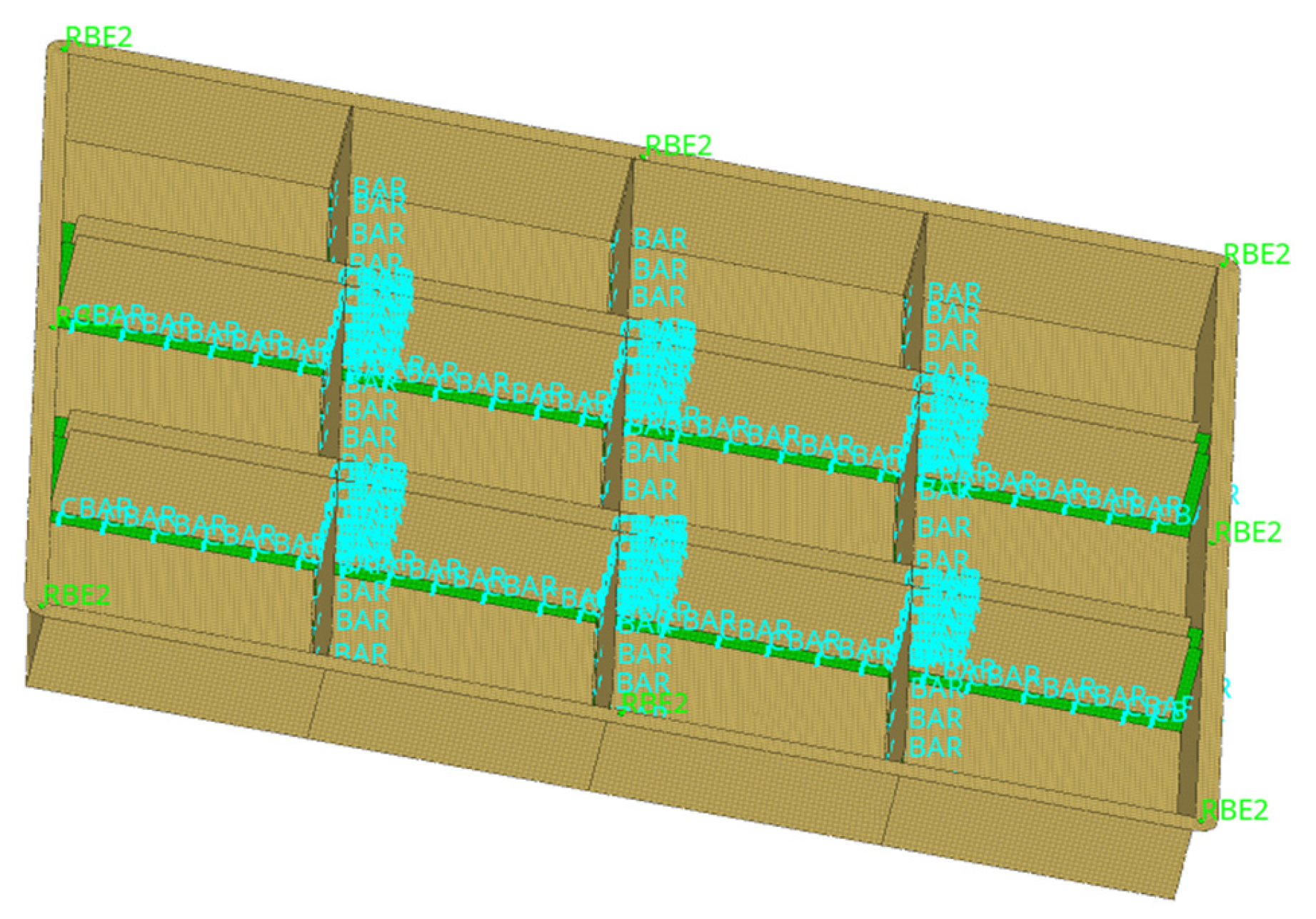
2.3. Modelling the Quick-Replacement Battery Box Welding Points

To improve the accuracy of analysis, the cell of bar (Cbar) was used for simulation. The cross-sectional forces and torques of the beam unit are computed through computer-aided engineering (CAE) while determining the nominal stress of the local structures at welding points [20]. This mainly connects the two grid nodes and sets a beam unit (with a diameter of 4 mm) to simulate the welding connection form. Then, the fatigue on the welding points is analyzed, resulting in an evaluation value. After analyzing the structure of the quick-replacement battery box, it was found that the required number of welding points and their distribution area are mainly concentrated at the junction of the sheet metal parts between the upper and lower boxes, as well as at the contact surface between the beam and bottom plate. This is also the area wherein stress concentration occurs in the connection of the quick-replacement battery box (as shown in Figure 2).

3. Analysis of Welding Point Characteristics of the Quick-Replacement Battery Box

3.1. Grid Division

Before analyzing the characteristics of the quick-replacement battery box, it is necessary to optimize grid quality in order to satisfy its requirements in terms of grid size, unit properties, and density. The number of grids has a significant impact on both the accuracy and speed of calculations. Generally, increasing the number of grids leads to improved accuracy, but also results in longer computation times [13]. When setting model properties, stress in the thickness direction can be ignored to facilitate calculation. Therefore, shell units can be effectively used to simulate the box model’s thickness. Ultimately, 77,398 grids and 77,232 nodes were divided, and the divided grids had to be checked and corrected (as shown in Figure 3).

3.2. Selection of Material Parameters

Aluminum alloy and carbon fiber materials are ideal choices for meeting the lightweight requirements of quick-replacement battery boxes for electric vehicles. However, the most widely used is still steel stamping. The basic material parameters of the quick-replacement battery box are shown in Table 1 [10].

3.3. Static Properties and Modal Analysis

To understand the static characteristics and modal characteristics of the quick-replacement battery box and its welding points, for electric vehicles, five particular working conditions of electric vehicles were analyzed: sharp braking, sharp turning, bumpy road, sharp braking on a bumpy road, and sharp turning on a bumpy road [13].

3.3.1. Working Condition 1: Sharp Braking

The vehicle load during sharp braking is mainly represented by an acceleration of 5 g in the X direction. A stress cloud map of the quick-replacement battery box and welding points is shown in Figure 4a. It can be seen from Figure 4a that the stress value of the quick-replacement battery box and welding points is small, indicating that the welding points are not affected by this stress. The displacement cloud map of the quick-replacement battery box and welding points is shown in Figure 4b. It can be seen from Figure 4b that the deformation of the quick-replacement battery box and welding points is mainly concentrated in the partition, and shows a forward bulging trend.

3.3.2. Working Condition 2: Sharp Turning

The vehicle load during sharp turning is mainly represented by an acceleration of 3 g in the Y direction. The stress cloud map of the quick-replacement battery box and welding points is shown in Figure 5a. It can be seen from Figure 5a that the main bearing stress of the quick-replacement battery box occurs on the top of the partition parts, while there is no obvious stress concentration at the welding points. The displacement cloud map of the quick-replacement battery box and welding points is shown in Figure 5b. It can be seen from Figure 5b that the main bearing stress of the quick-replacement battery box is on the top of the partition piece, while the deformation at the welding point is not obvious.

3.3.3. Working Condition 3: Bumpy Road

The vehicle load when moving on a bumpy road is mainly represented by an acceleration of 11 g in the Z direction. The stress cloud map of the quick-replacement battery box and welding points is shown in Figure 6a. It can be seen from Figure 6a that the stress is concentrated at the middle bottom of the quick-replacement battery box, while the welding points in the middle partition are under great pressure. The displacement cloud map of the quick-replacement battery box and welding points is shown in Figure 6b. It can be seen from Figure 6b that the middle bottom of the quick-replacement battery box is significantly deformed relative to the partition, but the welding points in the middle partition maintain a stable connection.

3.3.4. Working Condition 4: Sharp Braking on a Bumpy Road

When sharply braking on a bumpy road, the vehicle load is mainly represented by an acceleration of 5 g in the X direction and an acceleration of 11 g in the Z direction. The cloud map of the quick-replacement battery box and welding points is shown in Figure 7a. It can be seen from Figure 7a that the stress of the quick-replacement battery box is mainly concentrated at the welding points in the middle bottom and the middle plate. The displacement cloud map of the quick-replacement battery box and welding points is shown in Figure 7b. As can be seen from Figure 7b, the deformation of the quick-replacement battery box mainly occurs at the boundary and the bottom partition, and sufficient stiffness is needed in the welding points to avoid cracking.

3.3.5. Working Condition 5: Sharp Turning on a Bumpy Road

When sharply turning on a bumpy road, the vehicle load is mainly represented by an acceleration of 3 g in the Y direction and an acceleration of 11 g in the Z direction. The stress cloud map of the quick-replacement battery box and welding points is shown in Figure 8a. It can be seen from Figure 8a that a large concentration of stress is shown at the welding points between the middle partition of the quick-replacement battery box. The displacement cloud map of the quick-replacement battery box and welding points is shown in Figure 8b. It can be seen from Figure 8b that the bolt connection is depressed, resulting in the corresponding deformation of the partition; the support function of the partition maintains the overall shape. In this condition, the welding points must have a certain stiffness to resist fatigue damage.
As can be seen from Figure 4, Figure 5, Figure 6, Figure 7 and Figure 8, the stress concentration and displacement of the quick-replacement battery box and welding points are different under various working conditions. Under the condition of sharp braking on a bumpy road or sharp turning on a bumpy road, the welding points of the quick-replacement battery box show significant stress concentration and noticeable deformation. Particularly, during sharp turning on a bumpy road, the welding points require sufficient stiffness to maintain the overall shape of the quick-replacement battery box and resist fatigue damage. The maximum stress value is 2.038 × 10⁻¹, with a maximum displacement of 3.954 × 10⁻³.

3.4. Welding Fatigue Analysis

3.4.1. Welding Fatigue Analysis Theory [21]

The fatigue assessment of the welding points needs to consider damage in three areas: the welding points themselves, the main board connection, and the welding core.
(1)
The radial stress method was used to assess the damage between the welding points and the main board connection. n critical planes were selected cyclically along the welding point, and the radial stress in each plane was calculated. The damage value was then determined using the S–N fatigue assessment method, with the maximum damage value representing the damage at that position. The radial stress can be determined using the axial force fx, fy, fz and bending moments my, mz. The radial stress on different critical surfaces depends on the angle θ of the critical surface, as shown in Equation (1).
σ ( θ ) = σ max ( f x ) cos θ σ max ( f z ) sin θ + σ ( f x ) σ max ( m y ) sin θ σ max ( m z ) cos θ
where D is the diameter of the welding point and T is the thickness of the connected plate. σ max ( f y ) = f y π D T , σ max ( f z ) = f z π D T , σ max ( m y ) = κ 1.872 m y D T 2 , σ max ( m z ) = κ 1.872 m z D T 2 , κ = 0.6 T . when f x > 0.0 , σ ( f x ) = κ 1.744 f x T 2 ; when f x 0.0 , σ ( f x ) = 0.0 .
(2)
The damage assessment of the welding core requires the calculation of the positive stress and shear stress in the critical plane, as well as the determination of the maximum principal stress on that plane, using them, as shown in Equations (2) and (3).
τ ( θ ) = τ max ( f y ) sin θ + τ max ( f z ) cos θ
σ ( θ ) = σ ( f x ) σ max ( m y ) sin θ σ max ( m z ) cos θ
where τ max ( f y ) = 16 f y 3 π D 2 , τ max ( f z ) = 16 f z 3 π D 2 , σ max ( m y ) = 32 m y π D 3 , σ max ( m z ) = 32 m z π D 3 . When f x > 0.0 , σ ( f x ) = 4 f x π D 2 ; when f x 0.0 , σ ( f x ) = 0.0 .
After obtaining the shear stress and positive stress on the critical surface, the maximum principal stress on the critical surface is calculated using Equation (4).
σ 1 , 3 = σ 2 ( σ 2 ) 2 + τ 2
Stresses with large absolute values in σ1 and σ3 were considered for stress assessment, and the S–N stress assessment method was used to assess the damage on this critical surface. The maximum damage on all critical surfaces represents the damage at that point.

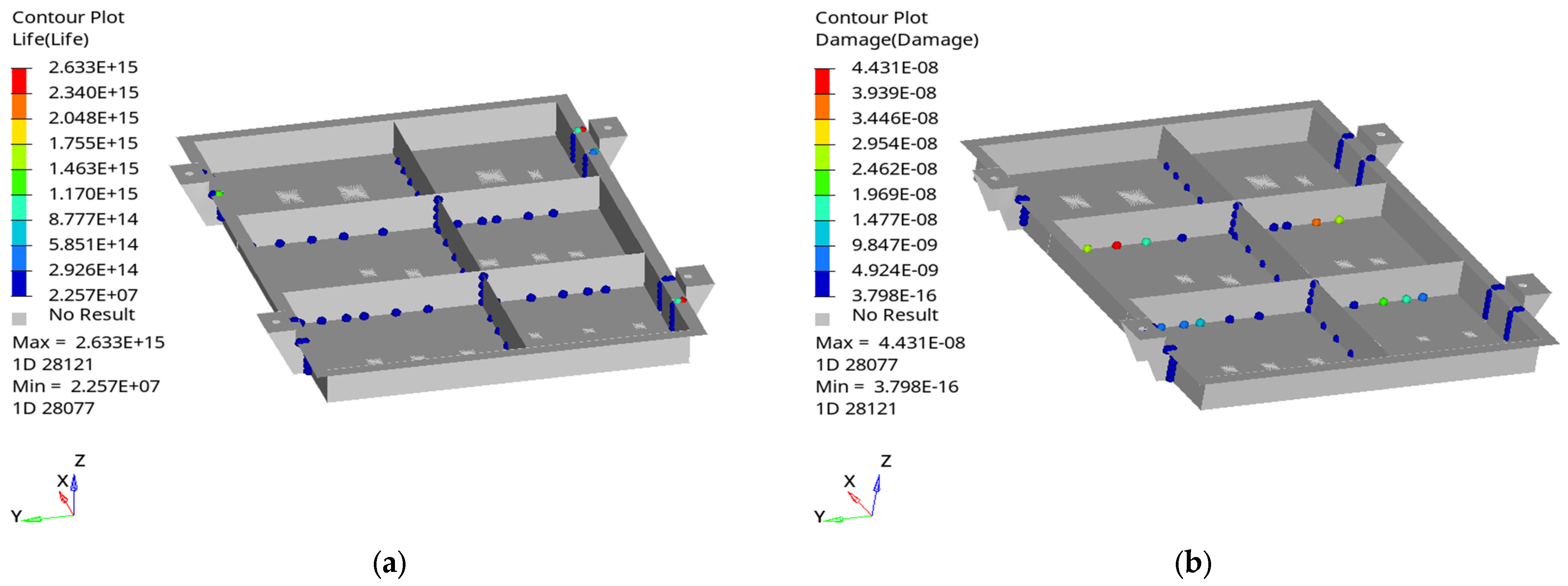
3.4.2. Welding Fatigue Analysis Results

This paper studies the fatigue reliability of the stress concentration in a quick-replacement battery box. Using Rupp’s equivalent structural stress as an example, the structural stress value can be directly calculated by combining the diameter of the welding core and plate thickness, after obtaining various loads on the welding core. This method is suitable for various types of specimens [22]. During the process of fatigue analysis, different fatigue events can be obtained by combining the load spectrum under various working conditions [21], allowing for the simulation of the effect of fatigue analysis on the welding points of the quick-replacement battery box. Finally, a cloud map of the fatigue life of and damage to the quick-replacement battery box and its welding points were obtained, as shown in Figure 9, Figure 10 and Figure 11.
As shown in Figure 9, Figure 10 and Figure 11, the largest fatigue damage of welding points is incurred at the junction of the middle compartment of the quick-replacement battery box. Three fatigue events resulted in maximum fatigue damages of 2.763 × 10⁻⁶, 3.833 × 10⁻⁶, and 6.728 × 10⁻⁶, respectively, with the maximum fatigue life reaching 9.421 × 10¹⁶, 2.904 × 10¹⁶, and 2.001 × 10¹⁶, respectively. This damage was equally distributed at the junction of the floor plate and the divider. This indicates that stress is concentrated at the junction of the middle partition of the quick-replacement battery box, which can easily lead to fatigue damage and cracking, thereby affecting the working life of the battery module.

4. Fatigue Analysis of Welding Points after Quick-Replacement Battery Box Optimization

4.1. Topological Optimization of Welding Points

The objective of topology optimization is to minimize the volume of welding points while satisfying the constraints of bending stiffness, torsional stiffness, and mode frequency. The design variable is the density of the welding point unit, and a mathematical topological optimization model of the quick-replacement battery box is shown in Equations (5)–(7).
Design   variable :   x j , j = 1 , 2 , 3 m
Objective   function :   f ( x i )
Constraint   condition :   g i min ( x ) g ( x ) g i max ( x )
where xj is the design variable; m is the number of design variables; f(xi) is the objective function of welding point volume; g i ( x ) is the constraint function; g i min ( x ) and g i max ( x ) are the upper and lower limit of constraint; and n is the number of constraint functions [23].
Relying on experience to arrange the welding points in the quick-replacement battery box may result in an inadequate number, which hinders the full utilization of structure and material properties, leading to increased material and cost. Furthermore, the unreasonable arrangement of welding points may also result in excessive local stress on the quick-replacement battery box and connection failure, and may even impact the safety performance of electric vehicles [24]. Therefore, the welding points of the quick-replacement battery box should be rearranged to improve performance before fatigue analysis on the optimized welding points. This may be achieved by setting multiple welding points with consistent performance at each connection and spacing each welding point between six and seven grids to avoid stress concentration, thereby ensuring firmness and reliability. The new layout has been further optimized through topology optimization to achieve a stable and robust structure, as shown in Figure 12.
As can be seen in Figure 12, the welding points at the lifting ear of the quick-replacement battery box cannot be ignored, and the number of welding points between the partition can be appropriately reduced. The topological optimization of welding points was analyzed for stiffness and volume; however, the results were not very rigorous. Therefore, further fatigue analysis was used in the simulation to improve the layout optimization of welding points and accomplish a fatigue life analysis of the quick-replacement battery box.

4.2. Optimized Welding Points Fatigue Analysis

A characteristics analysis of the welding points in the quick-replacement battery box showed that the top junction of the partition board has the largest damage fatigue evaluation value. This indicates that the welding method or structure needs to be optimized. Next, the fatigue tolerance of the optimized quick-replacement battery box will be analyzed to evaluate the battery box’s resistance to fatigue damage and to achieve further optimization. The detailed results of this analysis are shown in Figure 13, Figure 14 and Figure 15.
As shown in Figure 13, Figure 14 and Figure 15, the optimized structural material is more suitable for fixing the welding points. Compared with the pre-optimized structures, the maximum fatigue damage was reduced to 4.431 × 10⁻⁸, 4.562 × 10⁻⁸, and 8.885 × 10⁻⁸, respectively, with a corresponding increase in the maximum fatigue life of 2.633 × 10¹⁵, 1.235 × 10¹⁶, and 2.617 × 10¹⁵, respectively. This indicates that the optimized welding points operated within the fatigue range enabled by the quick-replacement battery box’s life safety, and they can effectively reduce its fatigue damage.

5. Conclusions

In this paper, a model of a quick-replacement battery box for electric vehicles was established using SolidWorks software, and the welding points’ fatigue was analyzed using the Optistruct module of HyperMesh software. The topology of the quick-replacement battery box was optimized according to the results of the analysis; finally, to achieve the goals of lightweight and an improved structural life, the fatigue of the welding points of the optimized battery box was analyzed for testing purposes.
(1)
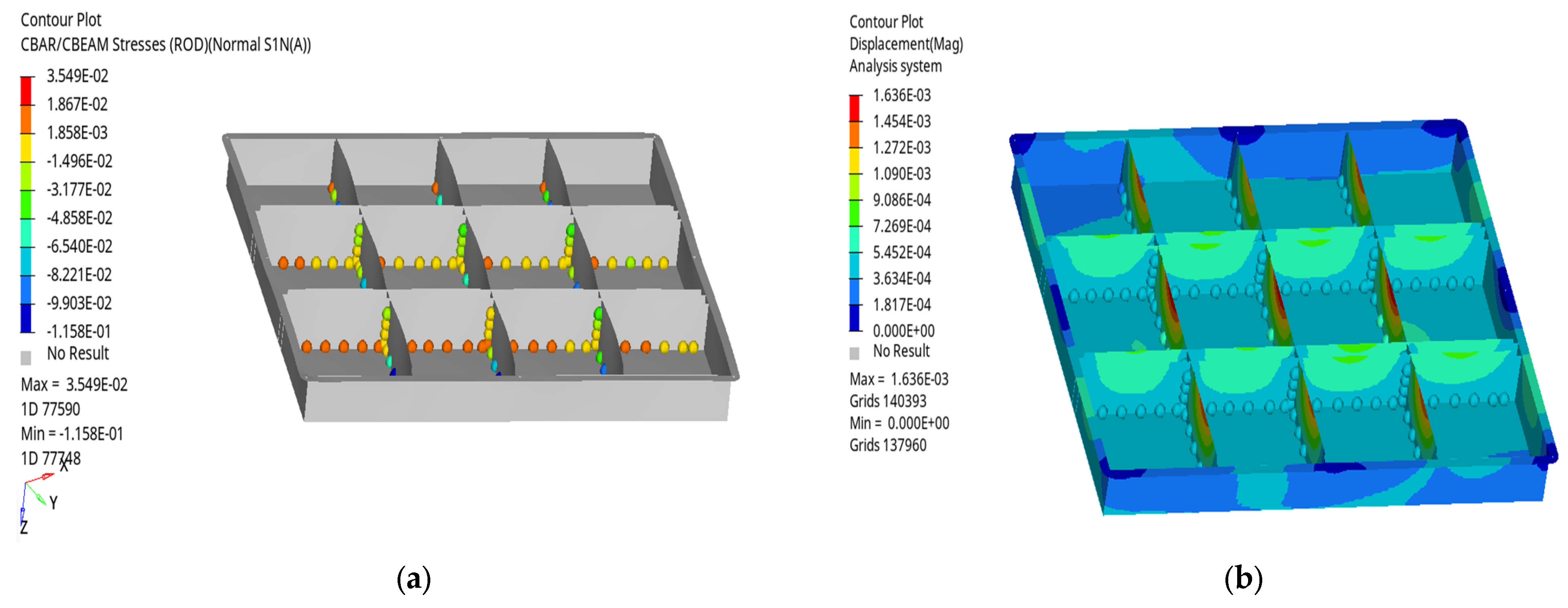
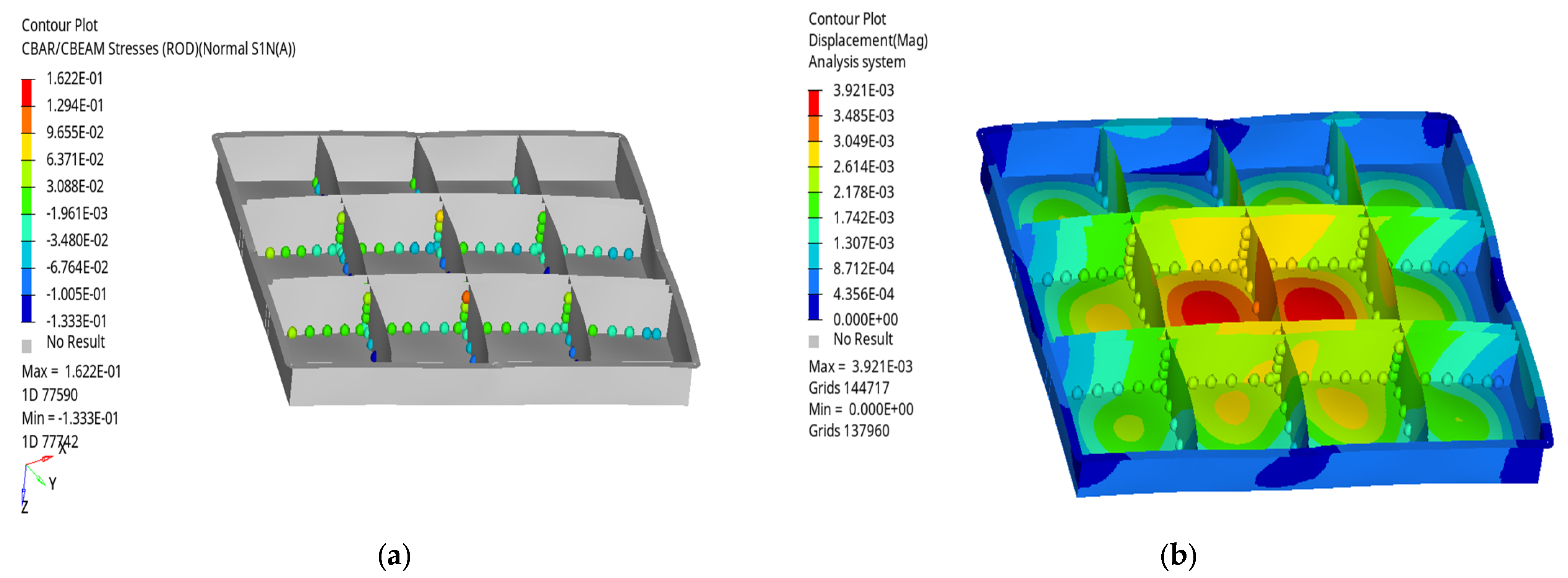
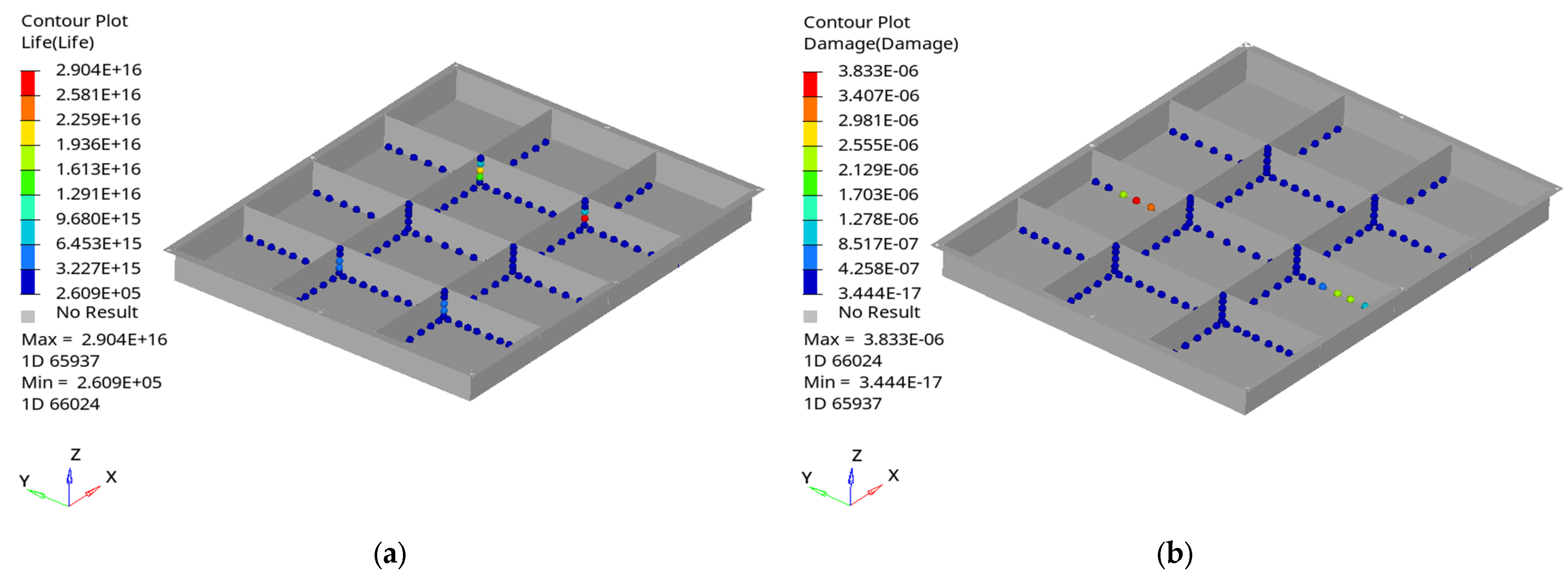
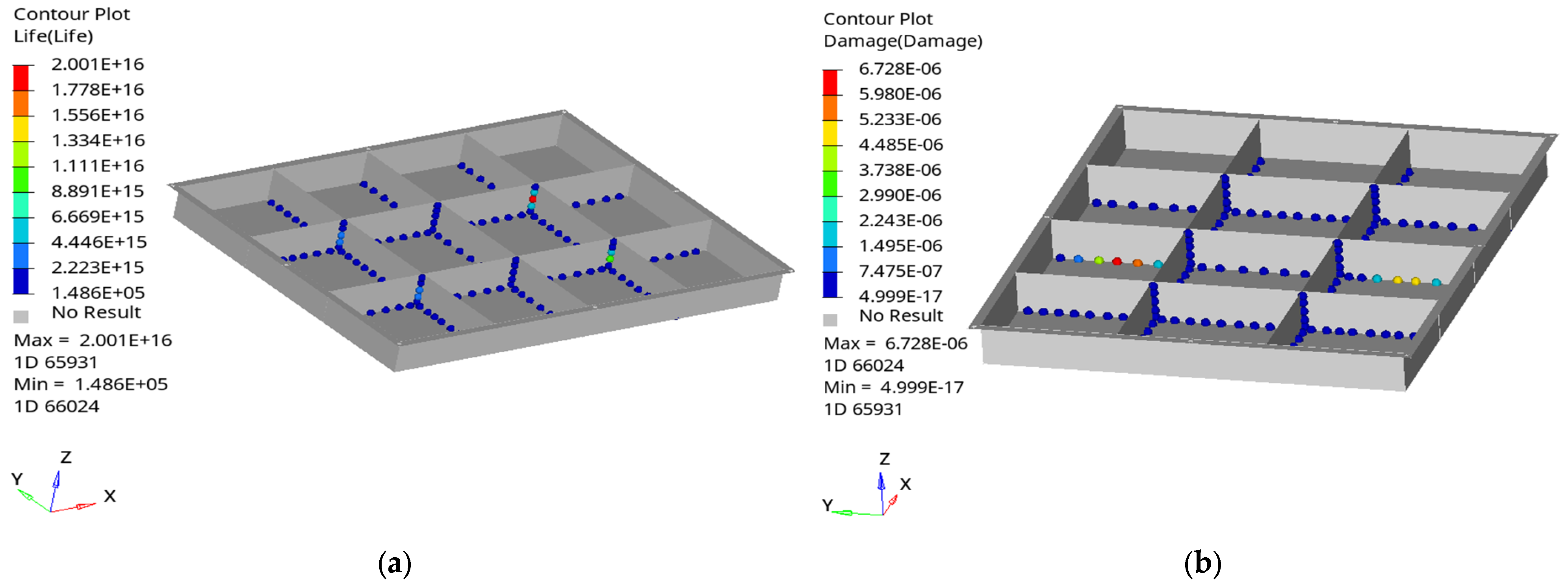
The static and mode analysis of the pre-optimized quick-replacement battery box revealed significant stress concentration and deformation occurring in the quick-replacement battery box and welding points during sharp turning on a bumpy road. The maximum stress value was 2.038 × 10⁻¹, with a maximum displacement of 3.954 × 10⁻³. However, these values fully satisfied the allowable stress and deformation requirements under various working conditions of the material. Additionally, the maximum fatigue damage of the welding points was 6.728 × 10⁻⁶ and the fatigue life was 9.421 × 10¹⁶, which far exceeds the required fatigue life for a quick-replacement battery box.
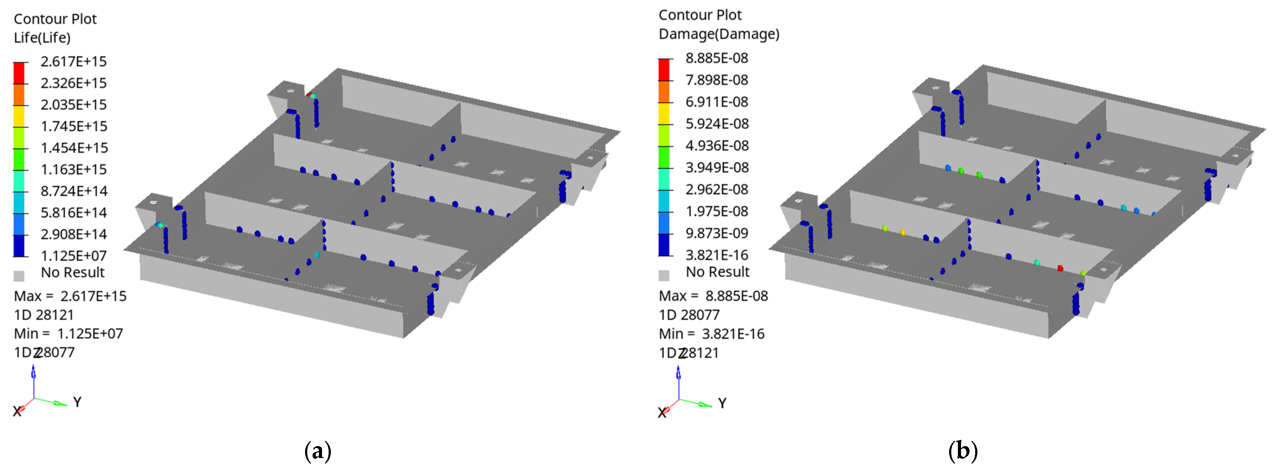
(2)
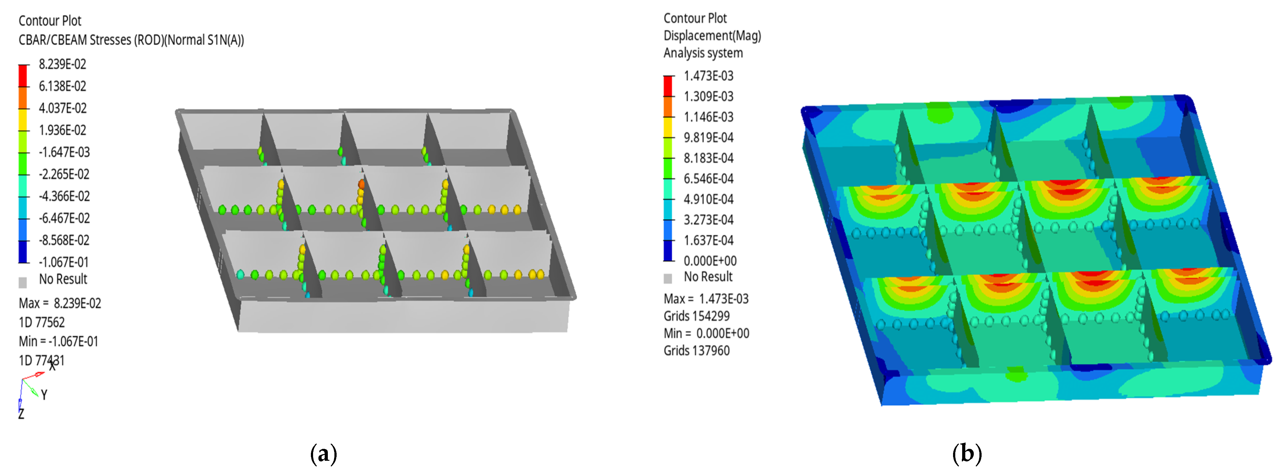
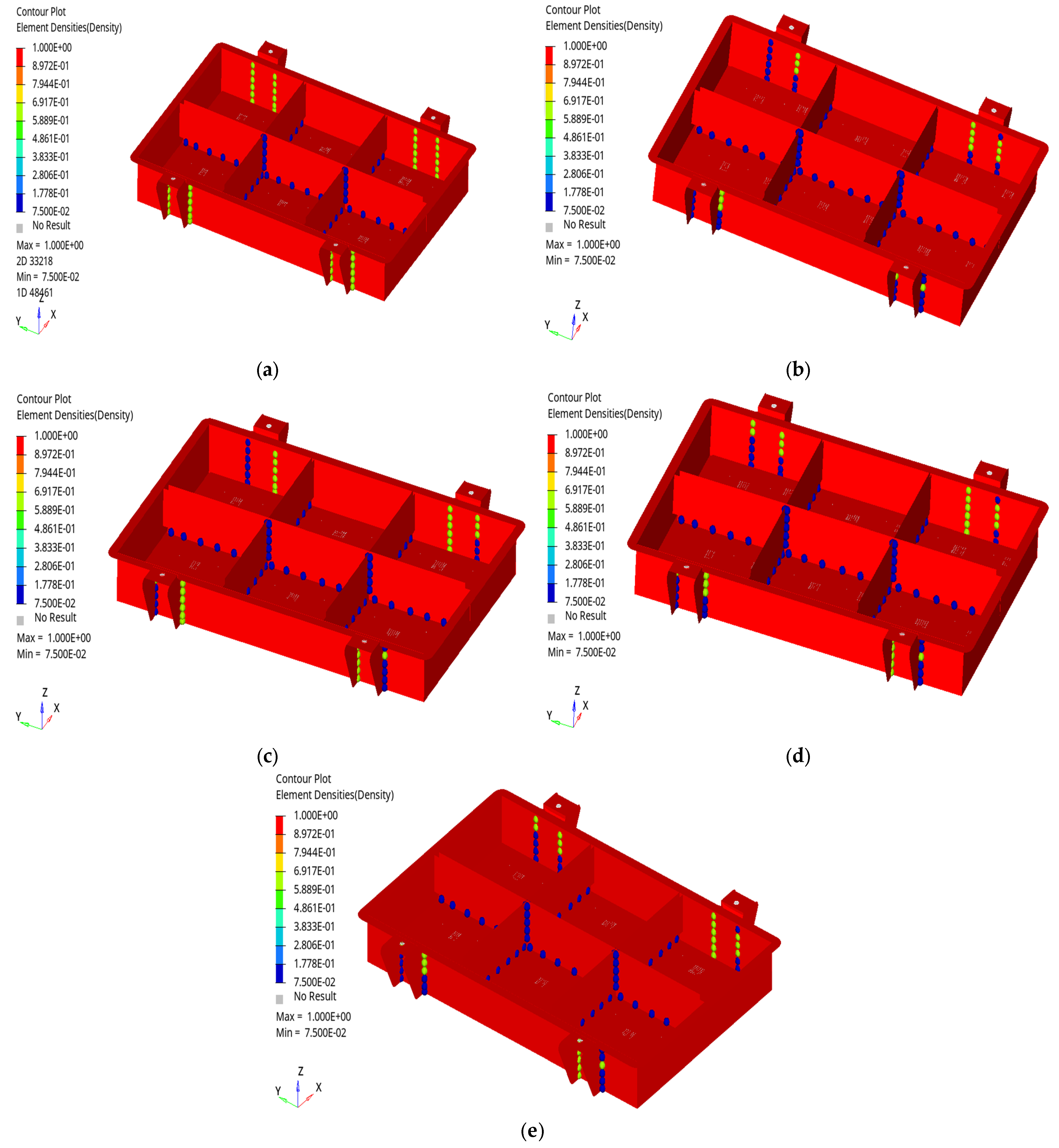
The stress concentration of the optimized quick-replacement battery box was relatively reduced, and the number of welding points was appropriately decreased. The fatigue analysis of the optimized welding points shows that the maximum fatigue damage was 8.885 × 10⁻⁸. Compared with that of the pre-optimized welding points, the maximum fatigue was 1.235 × 10¹⁶, which far exceeds the overall service life of the quick-replacement battery box; therefore, the layout of the optimized quick-replacement battery box and the welding points meets the requirements.
(3)
From the results of the fatigue analysis of the welding points, it can be seen that the quick-replacement battery box experiences maximum fatigue damage at its connections and in the center of the thin plate, which are areas vulnerable to potential damage. Furthermore, the analytical technique presented in this paper can be applied to analyze the welding fatigue of electric vehicles and to enhance their safety performance.

Author Contributions

J.L.: Writing—review and editing, methodology, investigation, formal analysis. J.Z.: Modeling, data curation and analysis. J.C.: Supervision, conceptualization. All authors have read and agreed to the published version of the manuscript.

Funding

This research was funded by the financial support of the Ministry of Education’s Collaborative Education Project, grant number 220603950174204; the Guangdong University Student Climbing Program, grant number pdjh2022b0554; and the Innovation and Entrepreneurship Projects for College Students, grant number 202210580009.

Data Availability Statement

Not applicable.

Conflicts of Interest

The authors declare no potential conflict of interest concerning the research, authorship, and/or publication of this article.

References

  1. Kalkan, O.; Colak, A.B.; Celen, A.; Bakirci, K.; Dalkilic, A.S. Prediction of experimental thermal performance of new designed cold plate for electric vehicles’ Li-ion pouch-type battery with artificial neural network. J. Energy Storage 2022, 48, 103981. [Google Scholar] [CrossRef]
  2. Wang, X.R. Analysis of the development, current research status and challenges of battery exchange modes for electric vehicles. J. Sichuan Vocat. Tech. Coll. 2021, 31, 163–168. [Google Scholar]
  3. Lu, Z.Y.; Zhang, W.G.; Zhao, M.Y.; Zhang, H. The simulation and optimization of fast-swap battery pack of EV based on frequency sweeping. Mod. Manuf. Eng. 2013, 63–68. [Google Scholar]
  4. Lu, Z.Y.; Zong, Y.Y.; Zhao, M.Y.; Zhang, H. Modal analysis and optimization of electric vehicle’s fast-swap battery box. Appl. Mech. Mater. 2013, 241, 1992–1999. [Google Scholar] [CrossRef]
  5. Wang, W.N.; Li, B.; Wang, Y. Design of battery fast-swap system for electric vehicle. Appl. Mech. Mater. 2014, 628, 190–194. [Google Scholar] [CrossRef]
  6. Qiu, C. The Research on Stowing of Fest-Exchange Battery Pack of Electric Vehicles. Master’s Thesis, Lanzhou University of Technology, Lanzhou, China, 2014. [Google Scholar]
  7. Li, S.Y.; Chen, Y.; Jiang, F.C.; Zhao, J.Z.; Wang, G.Y. Research on the finite element analysis and failure strengthening test of electric bus quick-change battery box. In Proceedings of the 2015 8th International Conference on Intelligent Computation Technology and Automation, Nanchang, China, 14–15 June 2015. [Google Scholar]
  8. Hou, W.N. Research on Structure and Thermal Performance for Fast-Exchange Battery Box of Electric Vehicle. Master’s Thesis, Chang’an University, Xi’an, China, 2018. [Google Scholar]
  9. Li, J.Y.; Lu, Z.D. Finite element analysis and optimization design of electric vehicle quick replacement battery box. Mod. Manuf. Eng. 2020, 31–38. [Google Scholar]
  10. Li, J.; Hu, G.; Chen, J. Analysis and Optimization of Fatigue Caused by Vibrations in the Quick-Replacement Battery Box for Electric Vehicles. World Electr. Veh. J. 2023, 14, 226. [Google Scholar] [CrossRef]
  11. Xu, Y.J.; Yang, L.; Lan, Z.B. Study on the fatigue characteristics of quick-change battery box in electric passenger car. Machinery 2023, 61, 1–6. [Google Scholar]
  12. Wu, C.D.; Dai, J.L.; Tang, W.; Yu, G.J.; Li, Y. Fatigue life prediction and optimization of welding spot based on battery box of a electric car. J. Mech. Strength 2013, 35, 663–667. [Google Scholar]
  13. Ji, Y.C. Research on Lightweight and Solder Joint Optimization Design of an Electric Vehicle Battery Case. Master’s Thesis, Anhui University of Technology, Ma’an shan, China, 2019. [Google Scholar]
  14. Lv, Z.D.; Zeng, J.X. Finite element analysis of the structural strength of the battery box in rail vehicles. Sci. Technol. Innov. 2021, 48–49. [Google Scholar]
  15. Xu, J.; Meng, X.W.; He, G.Q.; Li, G.Y. Numerical simulation and welding sequence optimization of friction stir welding for power battery enclosure’s bottom plate. J. Xi’an Jiaotong Univ. 2021, 55, 88–96. [Google Scholar]
  16. Xu, J.; Deng, F.; Su, T.; Li, G.Y. Research on numerical simulation and deformation control of melt inert-gas welding in power battery enclosure. Acta Sci. Nat. Uinversitatis SunYatseni 2021, 60, 50–58. [Google Scholar]
  17. Liu, S. Connection Analysis of Battery Box of Pure Electric Vehicle under Random Vibration Conditions. Master’s Thesis, Nanchang University, Nanchang, China, 2021. [Google Scholar]
  18. Cen, J.P. Understanding of the destruction mechanism on metal fatigue. Chin. J. Nat. 1980, 42–43. [Google Scholar]
  19. Tian, G.Z.; Yang, H.J.; Song, W.C. The production and prevention of welding stress. J. Tangshan Teach. Coll. 2010, 32, 45–46. [Google Scholar]
  20. Huang, Z.J.; He, L.; Zhang, H.W.; Liu, S.Y. Car body spot welding fatigue analysis based on the actual road spectrum. Intern. Combust. Engine Parts 2022, 49–52. [Google Scholar]
  21. Liu, Y.; Chen, B.; Luo, F. OptiStruct Structure Analysis and Engineering Application; Machinery Industry Press: Beijing, China, 2021. [Google Scholar]
  22. Zhao, J.W.; Feng, S.Z.; Tao, Y.R.; Li, Z.X. Stable node-based smoothed extended finite element method for fracture analysis of structures. Comput. Struct. 2020, 240, 106357. [Google Scholar] [CrossRef]
  23. Feng, S.; Xu, J.C.; Li, D.; Yang, L. Study on optimization of welding spot layout of automobile body. Agric. Equip. Veh. Eng. 2021, 59, 70–75. [Google Scholar]
  24. Yu, C. Research on Layout Optimization of Welding Spot for Automobile Body on the Topology Optimization. Master’s Thesis, Dalian University of Technology, Dalian, China, 2017. [Google Scholar]
Figure 1. A simplified model of the quick-replacement battery box: (a) lower box face unit model; (b) upper face unit model.
Wevj 14 00246 g001
Figure 2. Modelling the welding points of the quick-replacement battery box Cbar unit.
Wevj 14 00246 g002
Figure 3. Quick-replacement battery box grid division.
Wevj 14 00246 g003
Figure 4. Cloud map of stress and displacement of the welding points and quick-replacement battery box during sharp braking: (a) cloud map of stress; (b) cloud map of displacement.
Wevj 14 00246 g004
Figure 5. Cloud map of stress and displacement of the welding points and quick-replacement battery box during sharp turning: (a) cloud map of stress; (b) cloud map of displacement.
Wevj 14 00246 g005
Figure 6. Cloud map of stress and displacement of the welding points and quick-replacement battery box when moving on a bumpy road: (a) cloud map of stress; (b) cloud map of displacement.
Wevj 14 00246 g006
Figure 7. Cloud map of stress and displacement of the welding points and quick-replacement battery box during sharp braking on a bumpy road: (a) cloud map of stress; (b) cloud map of displacement.
Wevj 14 00246 g007
Figure 8. Cloud map of stress and displacement of the welding points and quick-replacement battery box during sharp turning on a bumpy road: (a) cloud map of stress; (b) cloud map of displacement.
Wevj 14 00246 g008
Figure 9. Fatigue analysis of the quick-replacement battery box and welding points at the first fatigue event: (a) fatigue life cloud map; (b) fatigue damage cloud map.
Wevj 14 00246 g009
Figure 10. Fatigue analysis of the quick-replacement battery box and welding points at the second fatigue event: (a) fatigue life cloud map; (b) fatigue damage cloud map.
Wevj 14 00246 g010
Figure 11. Fatigue analysis of the quick-replacement battery box and welding points at the third event: (a) fatigue life cloud map; (b) fatigue damage cloud map.
Wevj 14 00246 g011
Figure 12. Topological optimization cloud map of welding points of the quick-replacement battery box: (a) sharp braking; (b) sharp turning; (c) bumpy road; (d) sharp braking on a bumpy road; (e) sharp turning on a bumpy road.
Wevj 14 00246 g012
Figure 13. Fatigue analysis of the optimized quick-replacement battery box and welding points at the first fatigue event: (a) fatigue life cloud map; (b) fatigue damage cloud map.
Wevj 14 00246 g013
Figure 14. Fatigue analysis of the optimized quick-replacement battery box and welding points at the second fatigue event: (a) fatigue life cloud map; (b) fatigue damage cloud map.
Wevj 14 00246 g014
Figure 15. Fatigue analysis of the optimized quick-replacement battery box and welding points at the third fatigue event: (a) fatigue life cloud map; (b) fatigue damage cloud map.
Wevj 14 00246 g015
Table 1. Basic material parameters of the quick-replacement battery box.
MaterialDensity (g/mm3)Poisson’s RatioElasticity Modulus (Mpa)Yield Limit (Mpa)Anti-Pull Limit (Mpa)
DC017.850 × 10−90.32.07 × 105195340
Disclaimer/Publisher’s Note: The statements, opinions and data contained in all publications are solely those of the individual author(s) and contributor(s) and not of MDPI and/or the editor(s). MDPI and/or the editor(s) disclaim responsibility for any injury to people or property resulting from any ideas, methods, instructions or products referred to in the content.

