1. Introduction
In recent years, wireless power transmission technology has been increasingly used in industrial fields such as rail transit [
1,
2,
3,
4] and electric vehicles [
5,
6,
7,
8]. Resonant topology is the basis of the efficient transmission of wireless power systems. Reference [
9] compares the advantages and disadvantages of different compensation topologies and also compares their load characteristics as well as their open-circuit and short-circuit performances. The magnetic coupling mechanism of the primary side and the secondary side is the most important part of the wireless power transfer system. In order to improve the performance of wireless power transmission, a lot of literature has carried out a lot of research on it. Reference [
10] proposes using a DDQ coil and a BP coil to enhance the anti-offset ability, but this will use more copper and reduce the coupling coefficient. The H-core proposed in [
11] can have higher tolerance and efficiency in a larger air gap, but the magnetic flux leakage is more serious. The cause of the AC resistance of the coil is analyzed and the calculation of the AC resistance is studied in reference [
12,
13]. Reference [
14] analyzes the influence of increasing the coupling coefficient on the transmission performance of the system, points out that increasing the coupling coefficient can reduce the sensitivity of the system, and puts forward a method to optimize the coil to improve the coupling coefficient. The relationship between the coupling coefficient and the inner and outer radius of the coil is analyzed in [
15], and it is concluded that there is a small relationship between the coupling coefficient and the inner radius of the coil; however, with the gradual increase of the inner radius, its influence on the coupling coefficient cannot be ignored in practical application. Reference [
16] points out that mutual inductance is independent of wire diameter, puts forward a new method for calculating mutual inductance, which is verified through experiments, and provides certain methods to optimize the coupling coefficient when the size of the receiving coil is limited by space. The influence of the coupling mutual inductance parameters on the performance of radio energy transmission systems is analyzed in reference [
17]. It is pointed out that increasing mutual inductance can improve system efficiency, and the optimization conditions are given. In this paper, a new, comprehensive evaluation index of the system is proposed, which considers many factors such as efficiency, cost, and so on. Modeling research on wireless charging systems has also been carried out. Reference [
18] deeply studied the finite element modeling of a 5 KW system, provided calculation methods for power loss, equivalent circuits, and stray fields, and experimentally verified the obtained finite element simulation results, concluding that the error was less than 5%.
In order to increase the charging power, the high-current wireless charging coil can use multiple coils that are in parallel to improve the current level. Currently, a lot of research has been carried out on the application of multiple coils in the coupling mechanism. In [
19], using multiple receiving coils is proposed to improve overall system efficiency, but it does not consider the influence of coupling between multiple coils on the secondary side of the system. In [
20,
21], through the study of the coupling effect between multiple receiving coils and multiple transmitting coils in the wireless charging system, it is concluded that the resonant frequency of the system shifts under the coupling effect. It is necessary to re-adjust the compensation network parameters to improve efficiency. In [
22], a scheme using the parallel connection between double-layer coils on the original and secondary sides is put forward, the compensation capacitance of the current sharing coil is derived through the phase difference, and the current sharing effect is verified through experiments. However, a general model of the
n coils that are in parallel is not deduced in it, and the expression of compensation capacitance is a little complicated in it too.
A high-current wireless charging system uses a high-power density coil, which has high loss and causes the coil temperature to rise. If the temperature of the system is too high, it will affect the material properties of the magnetic core, reduce the coupling of the primary and secondary side coils, affect the transmission efficiency of the system, and cause a lot of security risks [
23,
24,
25]. The loss of the system is obtained through finite element simulation, and then the temperature of the coupling mechanism can be obtained through thermal simulation. Combined with the thermal simulation results, the coupling mechanism can be further optimized.
In this paper, the current sharing measure of multi-coils and multi-capacitors is proposed. First, the basic principle of the SS structure for wireless power transmission is deduced, then the current sharing model is derived for the parallel coils of the high-current wireless charging system, and the expression form of the compensation capacitor is obtained. Afterward, taking the parallel connection between the three coils as an example, the detailed current sharing equation is derived. The single capacitor compensation and the multi-capacitor compensation are simulated, and the simulation results are compared and analyzed to verify the effectiveness of the current sharing measure. The coils using the abovementioned two capacitance compensation methods are compared through disturbance simulation and thermal simulation, and the effect of current sharing measures on improving the anti-disturbance ability of the system and reducing the maximum temperature of the coil is analyzed. Finally, an experimental platform is set up to sample the current of each wire in the coil under two conditions as follows: no current sharing measures and current sharing measures. Furthermore, the effects of the current sharing measures are compared and verified.
2. Principle of Wireless Power Transmission in a SS Structure
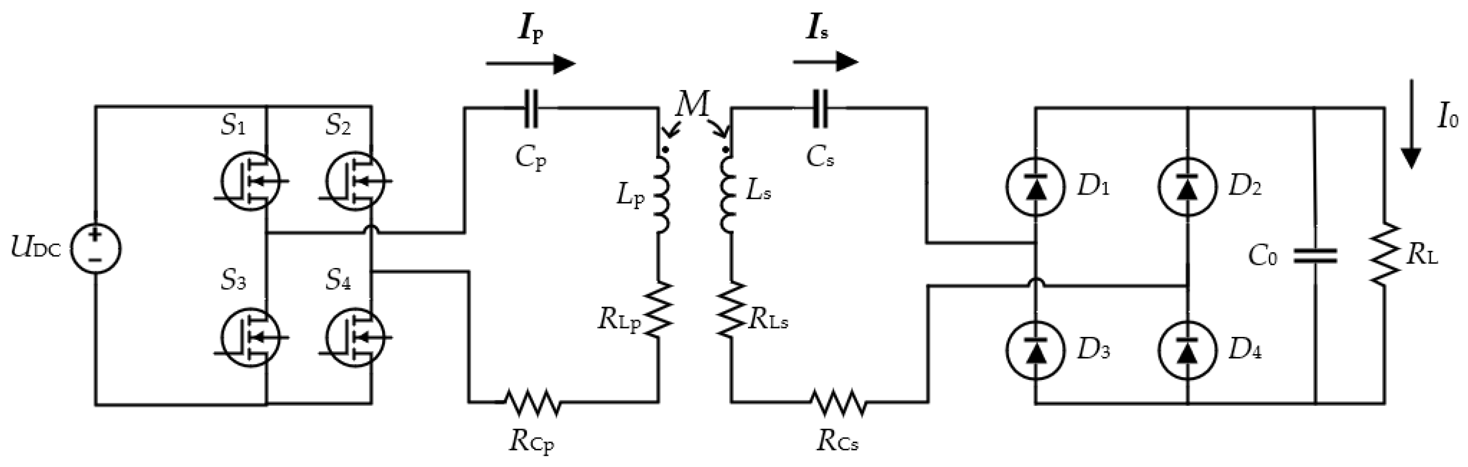
Figure 1 shows a schematic diagram of the SS structure for the wireless power transmission system. The DC power supply outputs a high-frequency AC voltage after passing through the inverter circuit. The primary side resonant circuit is composed of
Cp and
Lp, and the secondary resonant circuit is composed of
Cs and
Ls.
Lp and
Ls are energy transmission coils.
RL and
RC are the internal resistance of the inductor and capacitor, respectively.
Ip and
Is are the currents flowing through the primary and secondary coils, respectively. The alternating current is output through the SS compensation structure, which is passed through the uncontrollable rectification circuit composed of the diodes
D1,
D2,
D3, and
D4 and then filtered through the capacitor
C0 to obtain a stable direct current
I0 to supply power to the load
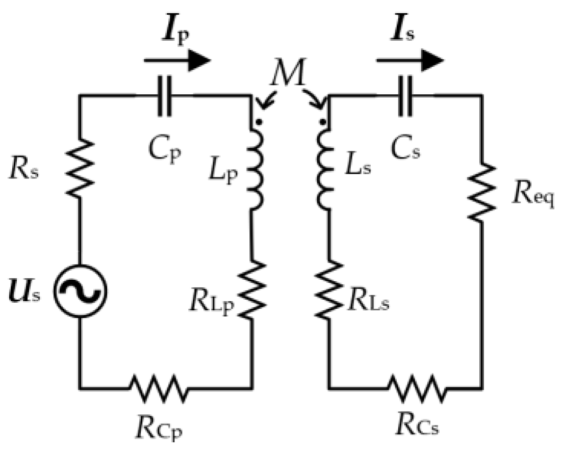
RL. The output of the inverter is equivalent to an AC current source
US and an AC source’s internal resistance
Rs, and the rectifier and load are equivalent to
Req in order to analyze its basic characteristics in which
Req = 8
RL · (π
2)
−1 [
26], as shown in
Figure 2.
According to
Figure 2 and Kirchhoff’s laws, the primary side current
Ip and the secondary side current
Is at resonance are obtained as follows:
where
If the internal resistance of the power supply, inductor, and capacitor is ignored, after simplifying Equations (1) and (2), the following current equation can be obtained:
The simplified current equation can effectively reduce the difficulty of system parameter matching, and these two formulas are used to determine parameters such as that of coil inductance.
According to the equivalent circuit above and Equations (1) and (2), the efficiency of the SS structure is obtained, and the expression of this is as follows:
Ignoring the internal resistance of the power supply and capacitor, the efficiency can be expressed in the form of a quality factor, as shown in Equation (7) and through the quality factor that is shown in Equation (8).
Qs is the quality factor of the receiving side. To improve efficiency, it is necessary to improve the value of the quality factor. However, in order to ensure the stability of the system, the quality factor of the receiving side should not exceed 10 as much as possible [
27]. The load of the high-current wireless charging system is relatively small, and the inductance of the receiving coil should also be low in order to limit the value of
Qs. To wind a receiving coil with a small inductance value that can withstand high currents, it is necessary to use multiple wires in parallel. However, the current inequality of multiple wires requires thicker wires, and the problem of local overheating of wires occurs. Therefore, it is necessary to study the current sharing measures among multiple wires.
3. Model of the Current Sharing of Coils and Efficiency Analysis
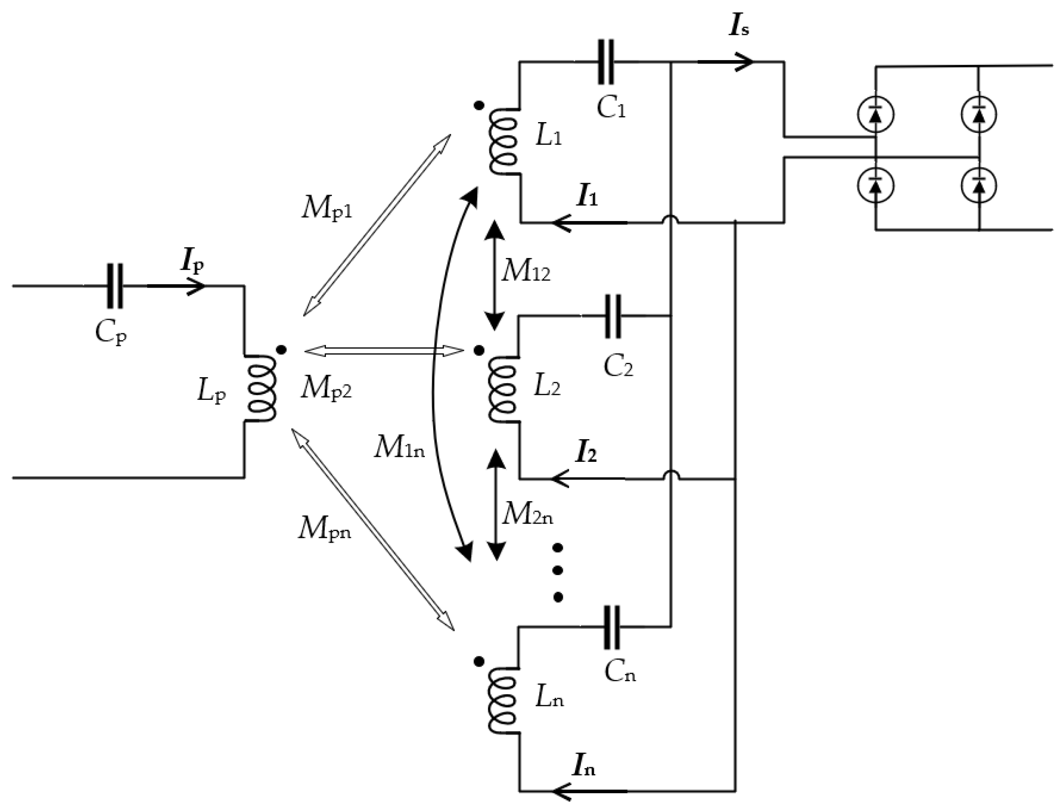
3.1. Analysis of n Branches Parallel to One Capacitor
With
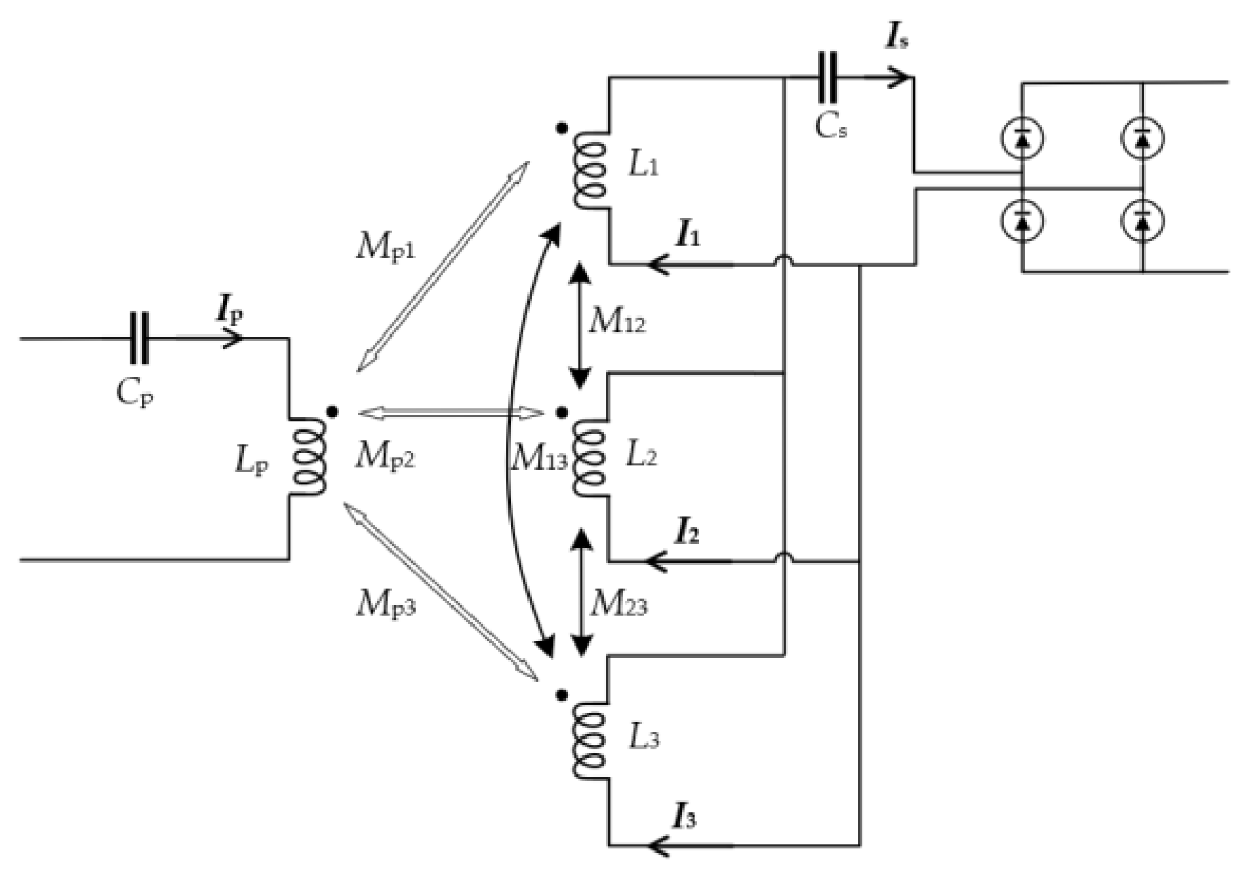
n branches being connected in parallel, the schematic diagram of the coil is shown in
Figure 3.
Lp and
Cp are the self-inductance and compensation capacitance of the transmitting coil, respectively.
Ii (I = 1, 2, …, n) is the current of the receiving coil
i.
Li is the self-inductance of the receiving coil
i, and
Cs is the compensation capacitor of the whole receiving coil.
Mpi is the mutual inductance between the transmitting coil and receiving coil
i, and
Mij (
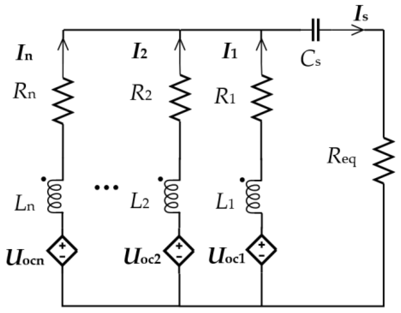
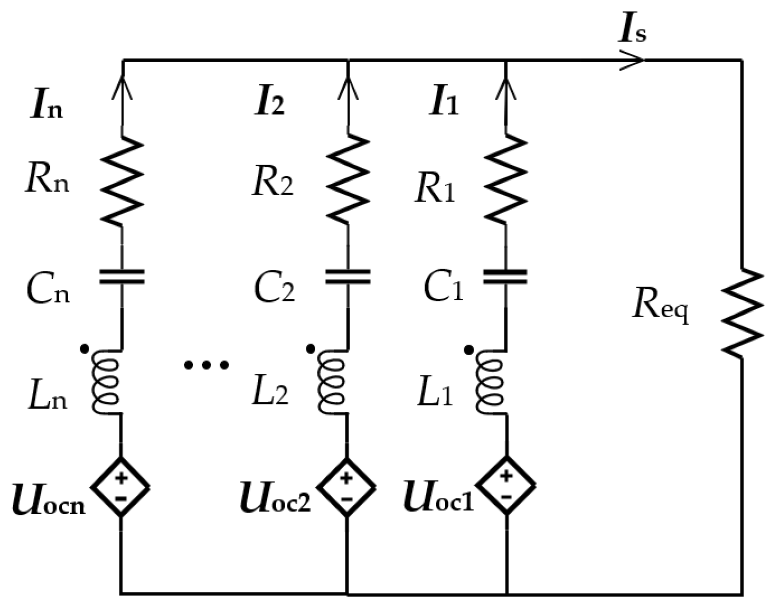
j = 1, 2, …, n) is the mutual inductance between the receiving coils. The coil diagram above is equivalent to the equivalent circuit diagram with a controlled source, as shown in
Figure 4.
Uoci is the induced voltage of the original side coil on the secondary side coil
i.
Ri is the AC resistance of each branch.
The calculation process of a capacitor compensation circuit is too complicated. The calculation form cannot accurately express the unequal current of each branch, so the unequal current state is expressed by simulation later.
3.2. Analysis of n Branches Parallel to Three Capacitors
With
n branches being compensated with n capacitors, the diagram is shown in
Figure 5.
Li and
Ci are, respectively, the self-inductance and compensation capacitance of the receiving coil
i. Other parameters are described above. The equivalent circuit diagram is shown in
Figure 6.
According to
Figure 6 and Kirchhoff’s laws, Equation (9) is obtained as follows:
Complete resonance compensation is adopted, and the capacitance is calculated according to the following:
By substituting Equation (10) into Equation (9) and letting
k11 =
I1/
I1,
k12 =
I2/
I1,
k13 =
I3/
I1, …,
k1n =
In/
I1, Equation (11) can be obtained:
The matrix form of Equation (11) can be expressed as follows:
where
The n formulas on the left side of Equation (11) are equal. I0 is allowed to be the effective value of the average current of n branches, namely that of I0 = (I1 + I2 + … + In)/n. When I1 is greater than I0, with I2, I3, …, and In being smaller than I0, the k12, k13, …, and k1n decrease. As a result, the left side of the first equation of Equation (11) becomes lower, and the left side of other equations becomes higher. Afterward, subject to the constraints of the equation, I1 needs to be reduced, and the currents of the other circuits need to be increased, thereby maintaining the current sharing state.
3.3. Analysis of Efficiency
The calculation equation, constraint condition, and extreme value of coil loss are as follows:
In Equation (17),
λ is a derivable parameter in the extreme value formula, and the extreme point of power can be obtained from Equation (18).
The unique extreme value point can be obtained, and the formula for calculating the
n current values of the extreme value point is shown in Equation (19).
The expression of the current value of the extreme point is similar to the expression of the resistance form of the parallel shunt with n paths. By comparing the special value of the boundary and the magnitude of the extreme value, it can be determined that the extreme value is the minimum value. For a coil wound with n parallel wires, the AC resistance of the n wires is basically equal, so the current value of the extreme value point is basically equal to the current value of the average current, thus achieving higher efficiency.
In the high-frequency Litz wire coil of a wireless power transmission system, the AC resistance [
12] includes a conductive resistance (
Rcond) and an induced resistance (
Rind), as shown in Equation (20).
The conductive resistance consists of the DC resistance and the equivalent resistance of the skin effect. For the system determined by frequency, its size is only related to wire parameters such as wire thickness and length [
13]. The induced resistance is the equivalent resistance of the proximity effect, which is related to the magnetic induction intensity of the adjacent wire to this wire [
28]; therefore, its size is not only affected by the parameters of the wire itself but is also related to the distance of the adjacent conductor. The higher the number of turns of the wire is or the closer the distance between the wires is, the stronger the magnetic field and the higher the resistance are.
For the coils in which two wires are connected in parallel, what affects the resistance is the conductive resistance because the induced resistance is the same, so there should be no gap between the two wires (the turn spacing between different turns of the same wire cannot be affected by this); therefore, the AC resistance of the two wires is basically the same. In the case that three or four wires are in parallel, the conductive resistance of the outer wire is higher, and the induced resistance of the middle wire is higher too. If the distance between the wires is zero, the influence of the induced resistance may be higher than that of the conductive resistance. Therefore, the distance between the parallel wires should be appropriately increased to reduce the induced resistance so that the resistance of the other wires except the innermost wire may be as close to the same as possible. If the number of parallel wires is more than four, the conductive resistance and inductive resistance of each wire can be basically equal according to transposition.
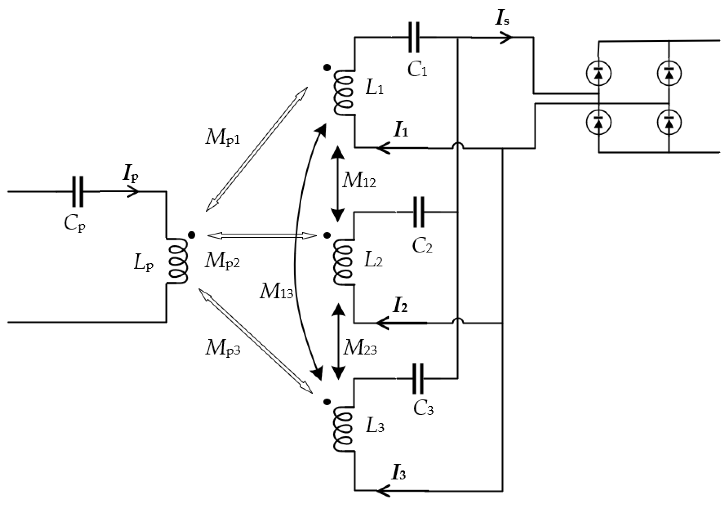
3.4. Analysis of Three Parallel Branches
Taking the three-coil example, the three capacitors are separated, and the resonant compensation is adopted, as shown in
Figure 7. The coil schematic diagram above is equivalent to the circuit of the sub-sideband-controlled source, as shown in
Figure 6, and the parameters are the same as those in
Section 3.1.
Through
Figure 8 and Kirchhoff’s laws, the equation is as follows:
The formula for calculating the capacitance value is as follows:
With
k12 =
I2/
I1,
k13 =
I3/
I1 being permitted, Equation (22) is substituted into Equation (21) to obtain the following:
Then, there is the following:
and then
A =
B =
C. When
I1 is higher than the average
I0 and the other circuit currents are less than
I0,
k12 decreases and
k13 decreases. Afterward,
A decreases,
B increases, and
C increases. Being subject to equality constraints,
I1 decreases, and other currents increase and maintain the current sharing state.
4. Simulation Verification of Parallel Current Sharing
The theoretical part of current sharing is derived above, and the simulation verification is carried out in this section. The simulation tools use Maxwell and Simulink, and the coupling mechanism is simulated in Maxwell to obtain the coil self-inductance and mutual inductance. Then, they are substituted into the Simulink simulation module to simulate the current sharing effect, and finally the Icepack simulation is used to compare the coil temperatures of the current sharing and uneven current sharing. The 100 A system is taken as an example. At the same power, increasing the primary voltage level can reduce the current level of the primary coil, thus reducing the loss of the primary coil and improving the efficiency. In addition, considering the voltage withstand level of the inverter, the primary DC voltage is 500 V. According to Equation (6), increasing the system frequency can improve the efficiency, but a higher system frequency will also lead to higher coil AC resistance loss and magnetic core loss. A single strand of thinner Litz wire is needed to reduce AC resistance. Considering the cost, a system frequency of 120 k and a Litz wire with a single-strand diameter of 0.05 mm are selected. According to the characteristics of the SS structure, the 100 A current at the load end is equivalent to 112 A in the AC circuit before rectification [
26]. In order to leave a certain margin, the effective value is 120 A. The coupling coefficient can be selected as 0.2. From the previous analysis, in order to ensure the stability of the system, the quality factor of the secondary coil should not be too high. After selecting the inductance of the secondary coil, the primary inductance can be calculated using Equation (4), and the compensation capacitance can be calculated according to the resonance of the capacitance and inductance. The selected system parameters are shown in
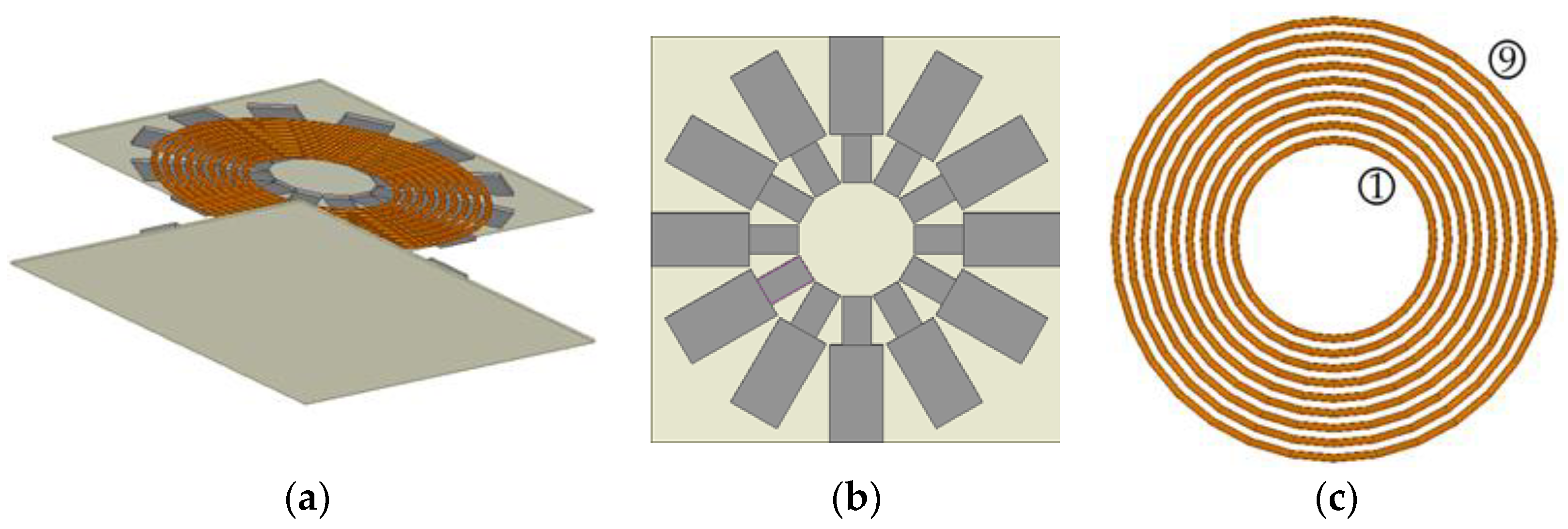
Table 1. The Maxwell simulation model includes coils, magnetic cores, and aluminum plates, and the three coils are coplanar and centered, as shown in
Figure 9a. The magnetic core used in
Figure 9a is a strip core, the schematic diagram is shown in
Figure 9b, the core parameters are calculated in reference [
29], and the strip core parameters are shown in
Table 2. The core material is PC95, and the thickness of the magnetic core is 5 mm [
30]. The aluminum plate is close to the magnetic core. The schematic diagram of the receiving coil is shown in
Figure 9c. The coil winding adopts the winding method whereby the pitch of coil is equal to the wire diameter [
31].
In
Figure 9c, the turns are numbered 1–9 from the inside to the outside. The first, fourth, and seventh turns are the first wires, which are connected in series and wound into coil 1. Similarly, the second, fifth, and eight ones are the second wires, which are wound into coil 2. The third, sixth, and ninth ones are the third wires, which are wound into coil 3. Then, the three coils are connected in parallel to form the receiving coil.
The mutual inductance between the transmitting coil and each coil on the receiving side and its resistance can be obtained by simulating the above model, as shown in
Table 3. The self-inductance of each coil on the receiving side and the mutual inductance between them are shown in
Table 4.
After the inductance value is obtained by MAXWELL and the capacitance value is then obtained by calculation, the current values of different wires can be obtained by Simulink. When using single capacitor compensation, the secondary side compensation capacitor
Cs is 349 nF. When using three capacitors for compensation, the value of the three capacitors on the secondary side can be calculated through
Table 4 and Equation (22). The calculation result is
C1 = 120 nF,
C2 = 114 nF, and
C3 = 115 nF. The Simulink model is built according to
Figure 6, and the simulated self-inductance, mutual inductance, and corresponding capacitance values are brought into the model.
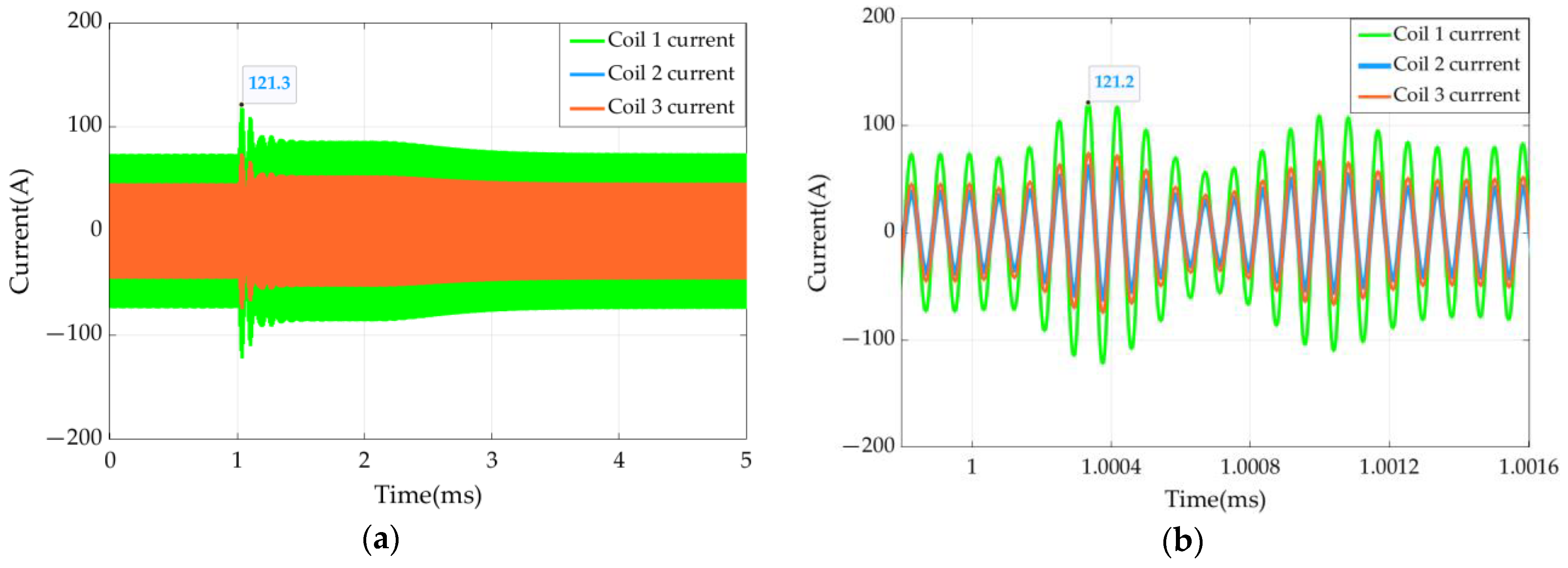
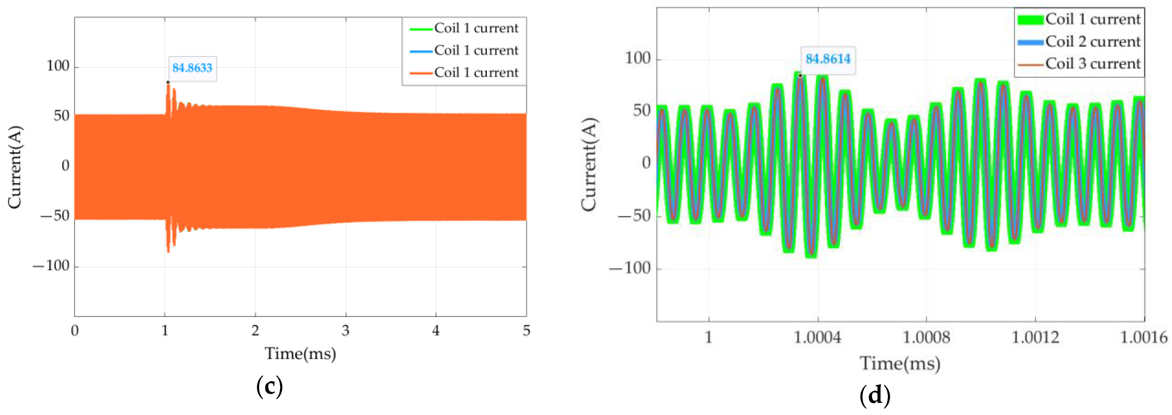
Figure 10 shows the currents when one capacitor is compensated, and
Figure 11 shows the currents when three capacitors are compensated.
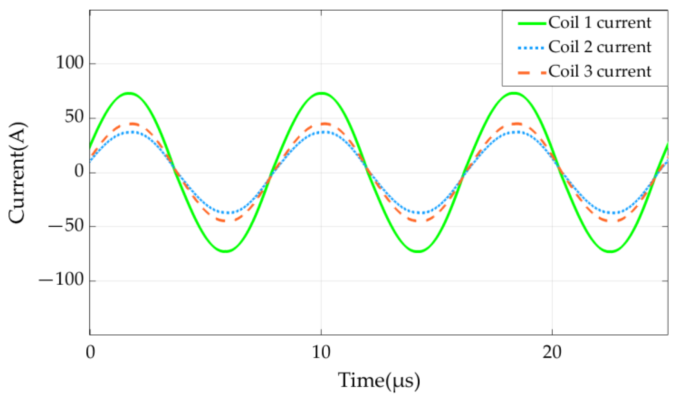
In
Figure 10, the effective values of the current of receiving coil 1, the current of receiving coil 2, and the current of receiving coil 3 are 52 A, 27 A, and 32 A, respectively. According to the previous Simulink simulation, this is caused by the different mutual inductance of the primary and secondary coils and the cross-coupling of the secondary coils. The abscissas of the three current waveforms in
Figure 11 have the same time. The peak currents of the three coils are 54 A, 53 A, and 53 A (effective value: 37 A), respectively. Therefore, the currents of the three coils have the same frequency and phase, and their magnitudes are basically equal. By comparison, the use of multi-capacitor compensation can effectively avoid the problem of the uneven distribution of the multi-coil current and prevent the coil from being damaged by an excessive coil current.
7. Conclusions
In this paper, a current sharing method of multi-branch and multi-capacitor compensation is proposed to solve the problem of the non-uniform current of multiple coils on the receiving side of a high-current wireless charging system, which leads to a poor anti-disturbance ability and a high local temperature. The calculation formulas of the compensation capacitance of each branch are derived and compared by simulation, and the following conclusions are obtained:
(1) The difference in the mutual inductance between the primary and secondary coils and the cross-coupling between the receiving coils leads to the non-uniform current of the secondary coils. By adding capacitors to each coil, the resonant compensation for the self-inductance of the coil, and the mutual inductance of the secondary multiple coils, the influence of an uneven current that is caused by different mutual inductance and cross-coupling can be eliminated.
(2) The current of the innermost coil is the highest, and its value is more than twice that of the coil with the smallest current, so the danger of an overload in the innermost coil is high when the load is disturbed. When the current sharing measure of multi-coil and multi-capacitor compensation is adopted, the current of each coil is basically equal, and the current of the innermost wire is obviously reduced.
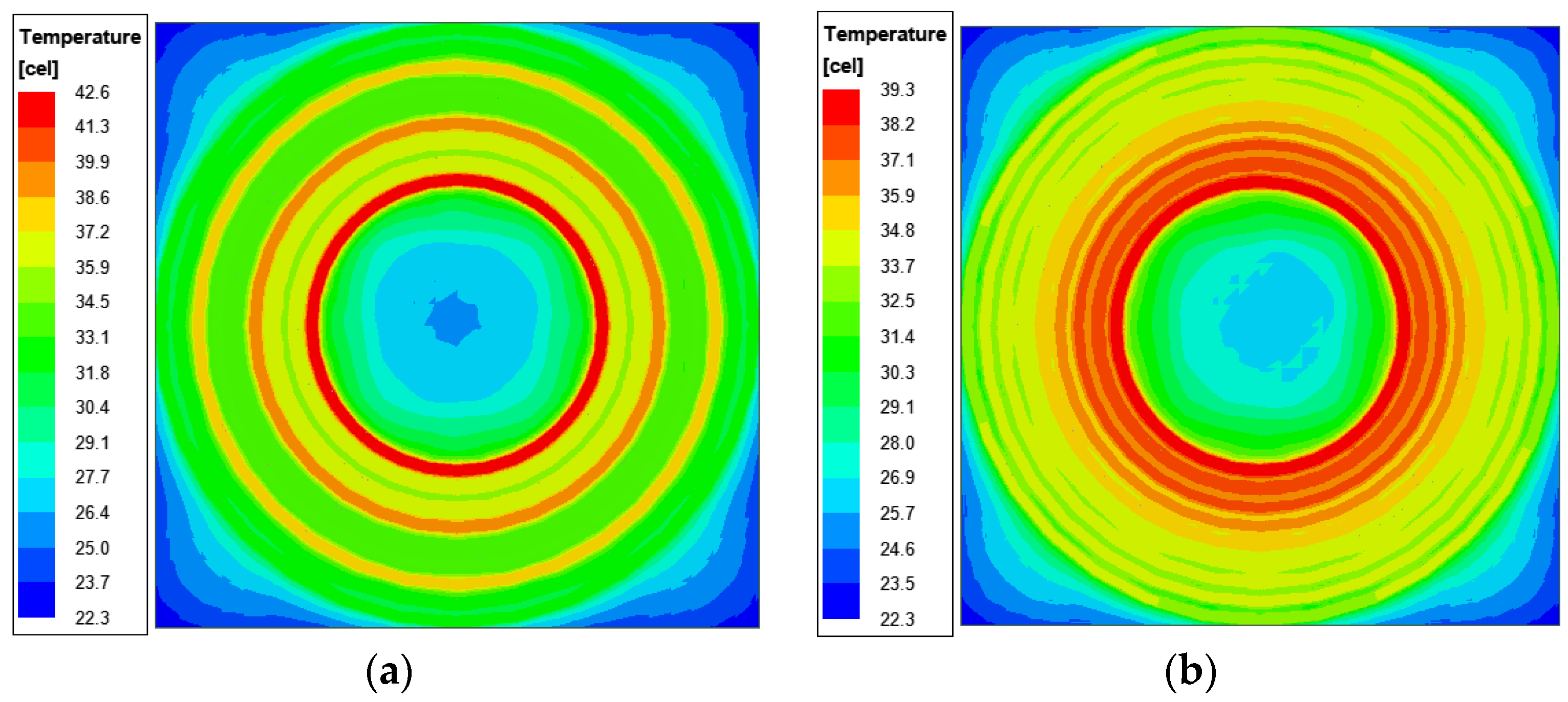
(3) When the current is uneven, because the innermost coil has the highest current, the temperature of the innermost coil is as high as 23 °C. After the current equalization measure is adopted, the current of the coil is significantly reduced, and its temperature is also reduced by 4 °C, which is a drop of up to 17%, thereby preventing the coil from overheating and effectively improving the safety of the system.
Finally, the effectiveness of the current sharing measure is verified through experiments, which provides a solution for the system design with a higher current level.


