Article

The Design and Optimization of a Novel Hybrid Excitation Generator for Vehicles

1
Department of Automotive Engineering, Hebei Vocational University of Technology and Engineering, Xingtai 054000, China
2
Hebei Special Vehicle Modification Technology Innovation Center, Xingtai 054000, China
3
School of Automobile and Transportation, Tianjin University of Technology and Education, Tianjin 300222, China
4
Department of Industrial Engineering, Arak University, Arak 38156879, Iran
*
Author to whom correspondence should be addressed.
World Electr. Veh. J. 2024, 15(4), 139; https://doi.org/10.3390/wevj15040139
Submission received: 26 February 2024 / Revised: 24 March 2024 / Accepted: 26 March 2024 / Published: 28 March 2024

Abstract

:
Silicon rectifier generators, which are single-excitation generators, are commonly used in vehicles. However, a traditional single-excitation generator cannot satisfy the requirements of modern vehicles due to its low efficiency, high failure rate and large excitation loss; a hybrid excitation generator is more suitable for a wide range of applications in vehicles because of its many advantages. In this study, a novel, high-efficiency and energy-saving hybrid excitation generator with a claw-pole series magnetic circuit for vehicles was designed. The magnetic circuit and principle of operation were analyzed. The structure parameters of the hybrid excitation generator were initially designed according to motor design theory. The model of the hybrid excitation generator was built based on the finite element method, and the no-load characteristic was analyzed. Furthermore, the influences of the permanent magnet thickness and core slot width on the performance of the generator were analyzed. According to the results, the structural parameters were optimized. The no-load output characteristics and load characteristics were compared between the generator and a silicon rectifier generator, and the test results show that the design, simulation and optimization methods were reasonable. This provides theoretical support and research methods for the development of a hybrid excitation generator.

1. Introduction

As the main power supply device, a generator provides the needed electric energy to many types of electric equipment, except starter motors, and undertakes the function of charging the battery. Without generators, the advancement and comfort of modern vehicles is impossible [1,2,3,4]. With the development of vehicle technology, increasingly more types of electrical equipment are used in vehicles, which greatly increases electricity consumption. Therefore, it is necessary to develop a new generator with better performance. A hybrid excitation generator (HEG) is a kind of generator that combines a permanent magnet and electrical excitation, an integrating motor, power electronics technology, new materials and other technologies so that the performance is significantly improved. An HEG uses the magnetic energy of a permanent magnet for the excitation, which reduces the excitation loss, and at the same time, the output voltage can be adjusted by the excitation current. Therefore, it not only has the good adjustment characteristic of a silicon rectifier generator but also has the advantages of high-power density, high efficiency and high reliability of a permanent magnet generator. It is suitable for operating conditions with variable speeds and loads [5,6,7,8].
Because an HEG has many advantages, many experts and scholars globally have carried out research in this field, and the structure and performance of HEGs have been continuously improved and innovated. Some scholars studied a type of stator chute built-in permanent magnet and salient pole electromagnetic compound excitation generator [9]. The magnetic flux per pole of the generator is only provided by a permanent magnet with a low magnetic field intensity. The structure used for the electric excitation is a traditional salient pole electric excitation rotor. It affects the service life of the generator to provide electric energy for an electric excitation winding using a carbon brush and a slip ring.
In [10], a HEG with a surface-mounted permanent magnet and claw-pole electromagnet was studied. The excitation part of the generator was a modified claw structure. The electric excitation winding was placed in the center of the flange and there was a margin on both sides. The permanent magnet part adopted a surface-mounted rotor structure. The additional air gap was large such that as the magnetic resistance increased, it tended to generate a leaked magnetic field between the top of both sides of the claw pole and the inner side of the permanent magnet yoke.
Some scholars studied a HEG with double-ended magnetic modulation. The permanent magnet part of the structure was a traditional built-in permanent magnet rotor, and two sets of electric excitation windings were placed on both sides of the stator to realize the compound excitation [11].
In [12,13], a type of HEG with a permanent magnet and electromagnetic parallel structure was proposed. In the structure, the electric excitation winding was placed on the stator, which realized no-carbon-brush slip ring excitation. The main air gap corresponding to the electric excitation rotor was less than the main air gap of the permanent magnet part, but the air gap between the electric excitation winding and the rotor was large, and the excitation efficiency was reduced.
In [14], a mathematical model of an HEG that considered the eddy current effect was established. Then, a three-dimensional finite element method was used to analyze the frequency characteristics of the generator. In [15], the finite element field–circuit coupling model of an HEG with tooth harmonic excitation and a rectifier load was established. The stator core loss under no load and two working conditions was calculated by using finite element simulation software.
In [16], a hybrid excitation generator structure with a slender salient pole called SSP-HEG was proposed. The magnetic circuit was analyzed using the finite element method. The main parameters of the permanent magnet excitation and electric excitation were designed. In [17], a HEG with a suspended brushless claw-pole electrical excitation rotor and combined magnetic pole PM rotor was proposed. The main structure parameters and the design method were analyzed, and a simulation analysis of the no-load magnetic field distribution and flux regulation ability was carried out using finite element software to verify the rationality of the hybrid excitation parallel magnetic circuit design.
In summary, many scholars have conducted in-depth research on the mechanisms and principles of HEGs, which provides valuable references for their development [18,19,20,21]. On this basis, first, a novel kind of HEG with a claw-pole series magnetic circuit for a vehicle is proposed in this paper; the magnetic circuit was analyzed and the main parameters of the HEG were determined. Second, a three-dimensional finite element model was established, finite element analysis was conducted based on finite element theory and the structure and performance of the HEG were optimized according to the simulation results. Finally, a prototype was manufactured and tested to verify the rationality of the design’s topology and theoretical analysis. This research provides theoretical and practical support for the improvement of a vehicle generator.

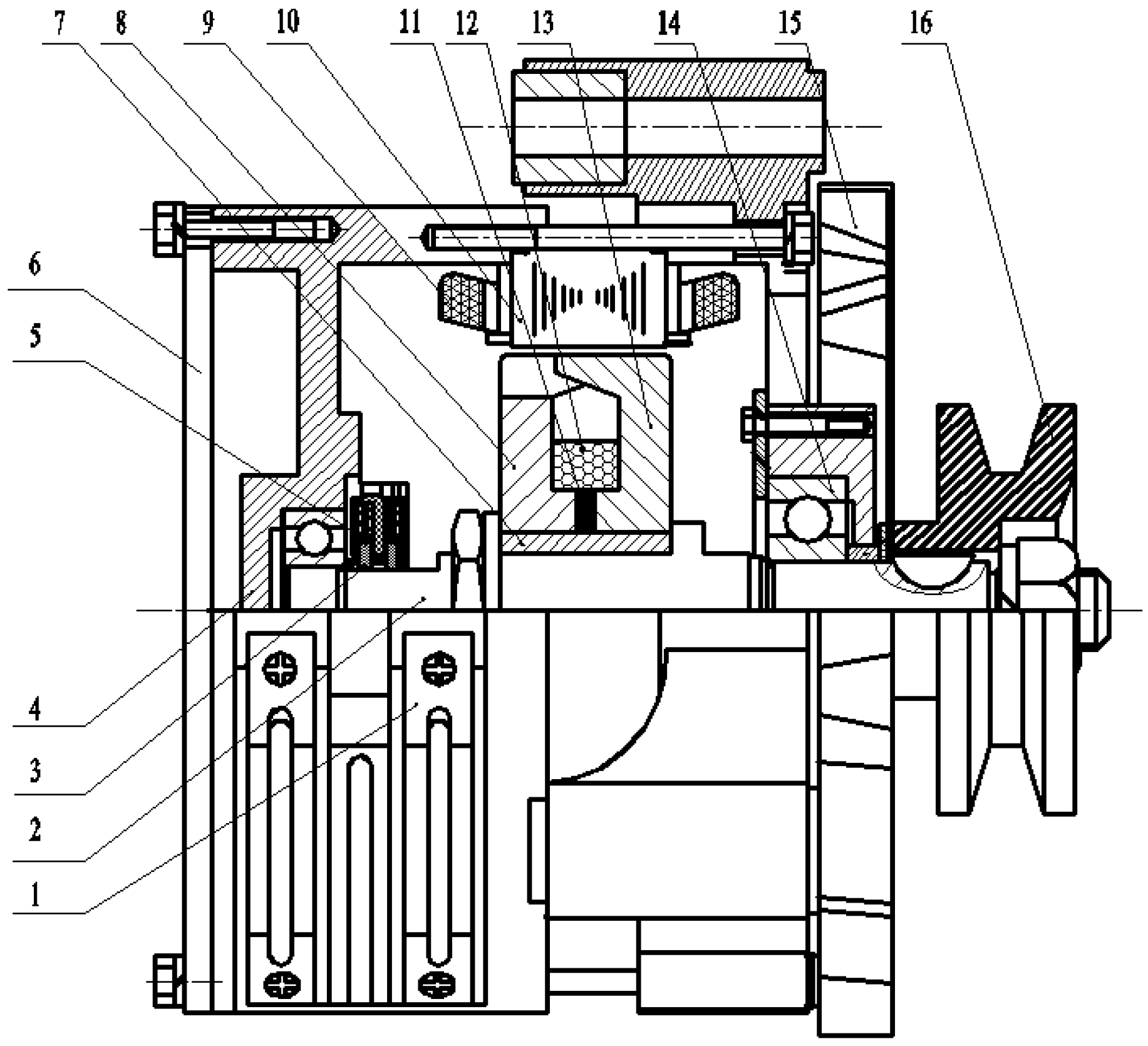
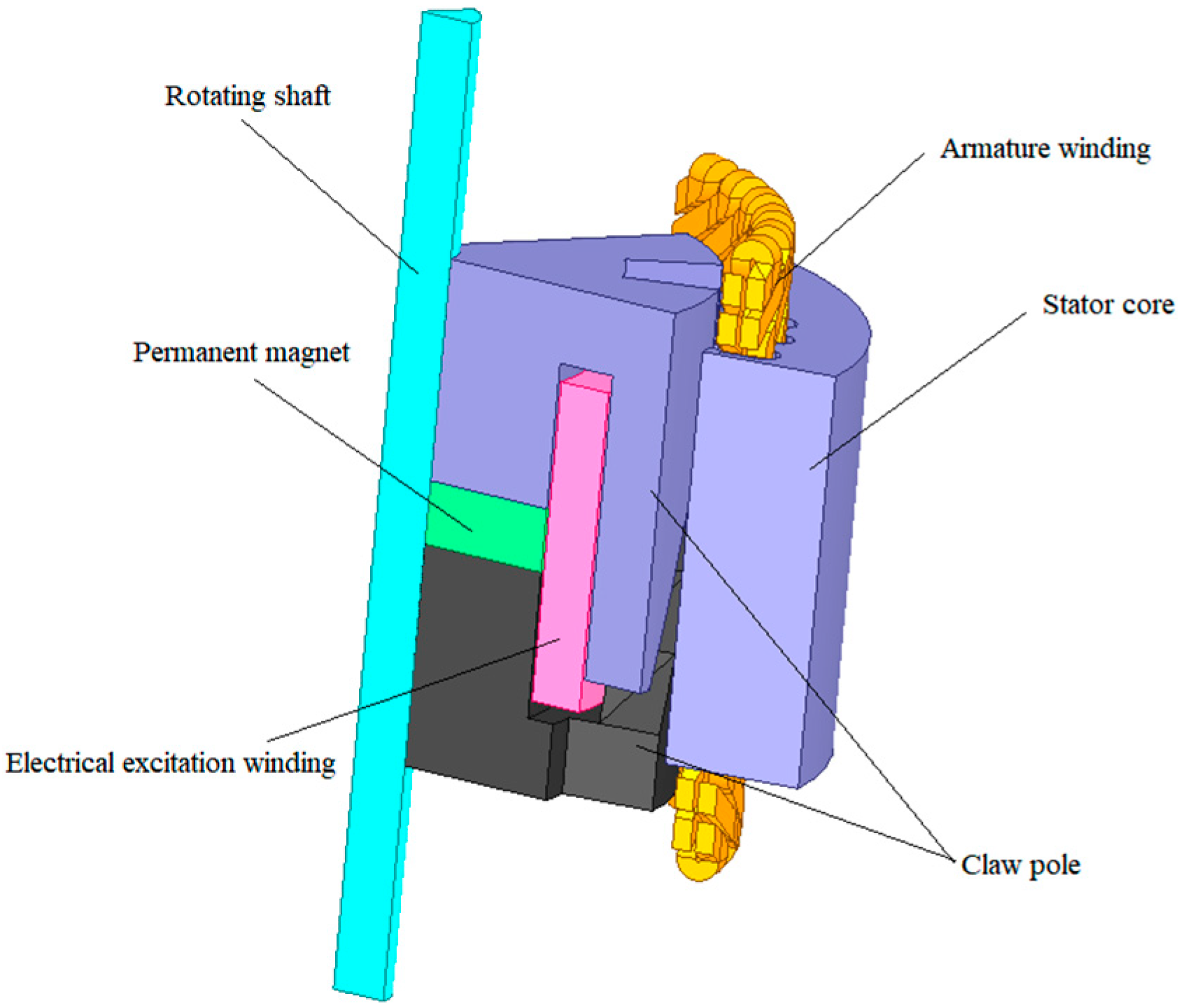
2. Overall Structural Design

In a claw-pole series magnetic circuit HEG, the permanent magnet circuit and the electrical excitation circuit share the same magnetic circuit. The permanent magnet is placed in the excitation winding and is axially magnetized. This arrangement is convenient for manufacture and the assembly is relatively simple. Furthermore, since the permanent magnet is arranged between the claw poles and surrounded by the excitation coil, its safety performance during operation is guaranteed, and accidents caused by the permanent magnet falling off will not occur [22]. A claw-pole series magnetic circuit HEG consists of two flange claw poles, a shaft, a ring-shaped permanent magnet, an armature winding with a plastic bracket, carbon brushes and slip rings, an electrical excitation winding, a cooling fan, etc. Its structure is shown in Figure 1. A ring-shaped rare earth permanent magnet is placed between the two flange claw poles, the convex part of the flange claw pole is surrounded by an electric excitation coil with a plastic tray and the magnetic isolation sleeve is equipped between the flange claw pole and shaft to reduce the leakage flux. The magnetic isolation sleeve is inserted into the hole of the claw-pole flange plate. The permanent magnet is placed between the front claw pole and the rear claw pole. The central hole of the permanent magnet is concentric with the hole of the claw pole. Cooling fans force the air into the generator to increase the heat dissipation efficiency. The metal slip ring is fixed at the end of the shaft and coordinates with the brush in the generator housing to transmit the current to the armature winding. The stator consists of a stator core and an armature winding. The armature winding is embedded in the slots of the stator core. The stabilizing controller is fixed on the surface of the rear-end cover.

3. Principle of Operation Analysis

The magnetic field in the air gap is established by a permanent magnet and an electric excitation winding, where the synthetic magnetic field in the air gap determines the output voltage; therefore, to keep the stability of the output voltage, the synthetic magnetic field must be adjusted. However, the load and speed of the generator are constantly changing; therefore, to maintain the output voltage stability, the synthetic magnetic field must be constantly changing according to the variation of load and speed [23].
When the speed of the engine reduces or the load of the generator increases, the output voltage reduces to below the rated voltage; to meet the demand for electric equipment in vehicles, the current passing through the excitation winding will increase appropriately, the electromagnetic field increases, the magnetic field density of the synthetic magnetic field increases and the output voltage increases to the rated voltage.
When the speed of the engine increases or the load of the generator reduces, the output voltage increases above the rated voltage; to protect the electric equipment and battery of the vehicle, the current passing through the excitation winding will reduce appropriately, the electromagnetic field increases, the magnetic field density of the synthetic magnetic field reduces and the output voltage reduces to the rated voltage.
In short, by adjusting the value and direction of the excitation current, the synthetic magnetic field in the air gap can be controlled to stabilize the output voltage of the generator.

4. Magnetic Circuit Analysis

The total flux of a generator is divided into the main flux and the leakage flux. The main flux is the part of the flux that passes through the stator core and generates electricity, while the rest is the leakage flux [24]. The leakage flux does not pass the stator core but goes through the air gap between the claw poles. Since the permeability of ferromagnetic materials is much higher than that of air, most of the magnetic flux passes through the stator core. The magnetic circuit of a claw-pole series magnetic circuit HEG is divided into a permanent magnetic circuit and an electromagnetic circuit, and they share the same path [25]. The magnetic circuit of the generator is shown in Figure 2.
Electro-excitation magnetic circuit: The excitation current is fed into the excitation winding. Due to the structural characteristics, an axial magnetic flux is generated, which is converted into a radial magnetic flux due to the action of the claw pole. The flux passes through the N pole of the claw pole and through the air gap to reach the stator. The stator teeth and stator slots are used to guide the magnetic field lines. The magnetic field lines pass through the stator teeth, the stator yoke, the air gap between rotor and stator, and return to the adjacent S pole of the claw poles; then, the radial flux is converted into an axial flux, returns to the N pole of the claw pole through the rotor yoke and the loop is formed.
Permanent magnet magnetic circuit: The magnetic flux starts at the N pole of the permanent magnet and passes through a claw pole. The axial magnetic flux is converted into a radial magnetic flux, passes through the air gap, reaches the stator teeth and the stator yoke, arrives at the stator teeth corresponding to the adjacent polarity claw pole, passes through the air gap again, returns adjacent to the claw pole and then the S pole of the permanent magnet, and the loop is formed [26,27].

5. Determination of the Main Parameters

5.1. Parameters of the Permanent Magnet

Regarding the requirements of electrical equipment for vehicles, the main technical indexes are shown in Table 1.
The short-circuit triangle method, shown in Formula (1), was used to preliminarily estimate the required volume of the permanent magnet [28]:
V M = ( P N ) cos ϕ = 0 σ 0 C F K a d 3.54 k B f B M 0 H M h k i 2 k i 1 × 10 8
where PN is the rated capacity of the generator, σ0 is the magnetic leakage coefficient, CF is the magnetic potential coefficient, Kad is the longitudinal armature reaction magnetic-potential-referring coefficient, KB is the transverse armature reaction magnetic-potential-referring coefficient, f is the frequency, BM0 is the magnetic induction of the generator with no load ( B M 0 = 0.85 B r ), Br is the remanent magnetic induction, HMh is the magnetic field intensity of a permanent magnet with a steady-state short circuit ( H Mh = 0.65 H CB ), ki is the short-circuit current multiple ( k i = 4 ) and cosφ is the power factor ( c o s φ = 0.85 ).
Δ V M = 0.125 V M
V M = ( 1 Δ V M ) V M
When the value of the power factor cosφ is greater than 0, the demagnetization effect of the longitudinal armature reaction to the permanent magnet decreases, and, thus, the volume of the required permanent magnet can be appropriately reduced according to the proportion. According to the relationship between the volume reduction percentage of the permanent magnet and the power factor in Figure 3, the percentage reduction in the volume of the permanent magnet was 12.5% when the value of cosφ was 0.85, and the volume of the permanent magnet was calculated using Formula (3).
Formula (4) was used for calculating the volume of a circular object:
V M = λ M D M [ π 4 ( D M 2 λ D M i 2 ) ]
where λM is the ratio of the thickness to the outside diameter of circular ( λ M = L M D M ), LM is the annular permanent magnet thickness, λD is the ratio of the inner diameter and the outer diameter of ring ( λ D = D M i D M ), DM is the outer diameter of the permanent ring magnet and DMi is the inner diameter of the permanent ring magnet.
The formula for the outer diameter of a ring permanent magnet can be derived to obtain the following:
D M = 4 V M π λ M ( 1 λ D 2 ) 3
Since the main flux of the rotor passes through the permanent magnet axially, and the magnetic resistance of the rare earth permanent magnet is large, the permanent magnet thickness should be minimized to reduce the magnetic field loss. The ratio of the thickness to the outer diameter of the annular permanent magnet λM was 0.04, and the ratio of the inner and outer diameter λD was 0.45. The calculated parameters of the permanent magnet are shown in Table 2.

5.2. Parameters of the Excitation Coil

According to Ohm’s law for a magnet circuit [29],
N I = BL μ I
Formula (7) can be deduced according to Kirchhoff’s second law of magnetic circuits:
  HL =   N I
In Formula (7), H is the magnetic field intensity, L is the length of each magnetic circuit, I is the current in the electromagnetic winding and N is the number of turns of the electrical excitation winding. Formula (8), which is used for calculating the number of turns of the excitation winding, can be obtained by combining Formulas (6) and (7):
N = B μ I ( 2 σ ) + B μ F e I ( L 1 + L 2 )
where NL is the number of turns, B is maximum magnetic induction ( B = 1.5 T ), σ is the air gap, I is the current intensity in the field winding, μ0 is the permeability of a vacuum, μFe is the permeability of steel, L1 is the length of the magnetic circuit in the silicon steel sheet and L2 is the length of the magnetic circuit in the claw pole.
According to Formula (8), the number of turns of the excitation winding was calculated and its value was 334.

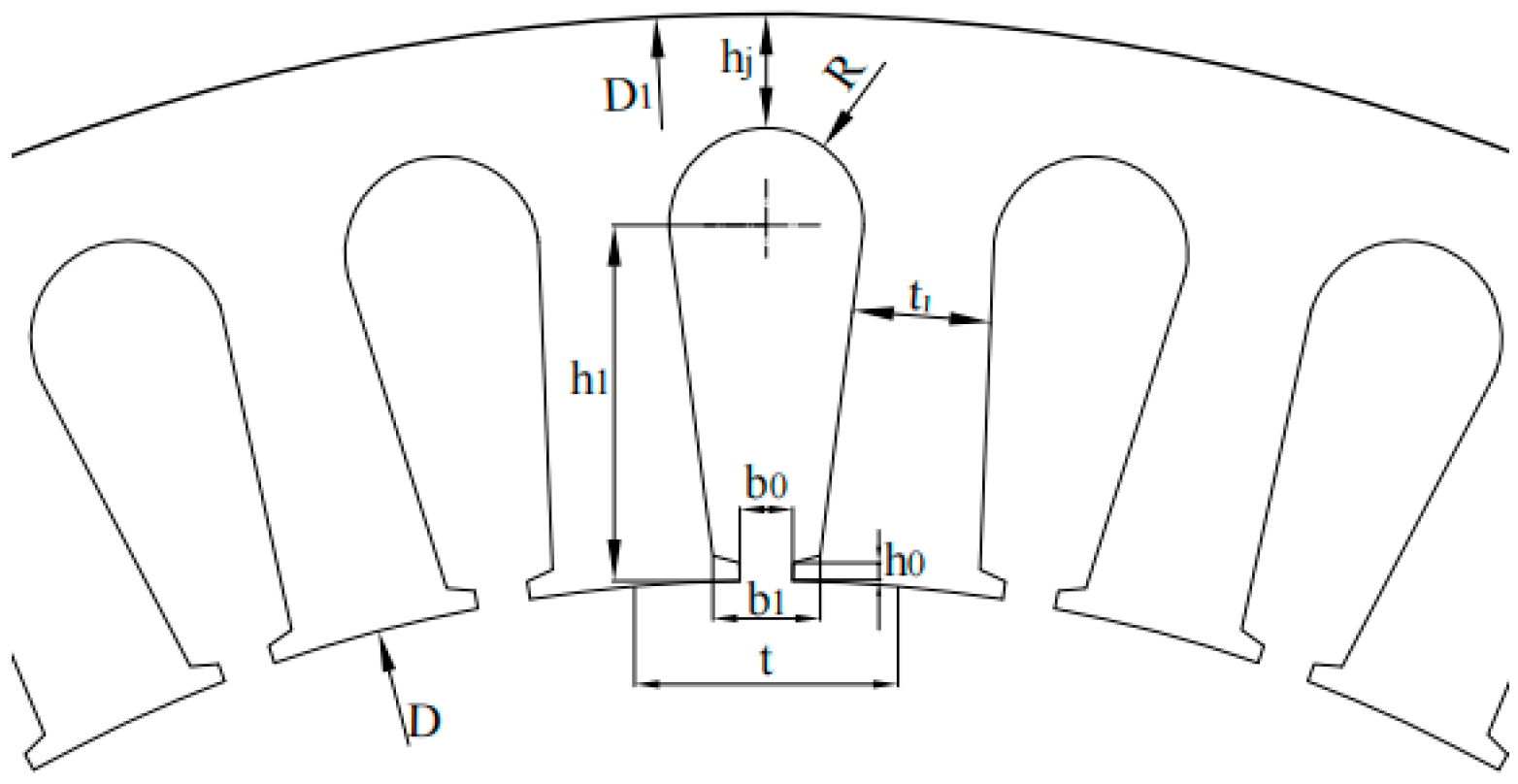
5.3. Parameters of the Stator

The stator winding is embedded in the stator slot. The generator for a vehicle generally adopts a pear-shaped or trapezoidal slot. A pear-shaped slot was adopted in this design.
The number of turns of each phase armature winding can be obtained from Formula (9):
W = E 0 4 f K B K w Φ u 0 × 10 8
where KB is the transverse armature reaction magnetic potential reduction coefficient, f is the frequency, KW is the winding coefficient and Φu0 is the no-load effective flux.
The number of turns of each phase of armature winding was taken as 42; since one turn of the armature winding contains two conductors, the number of conductors in each phase in the series was 84, and there were seven conductors in each slot.
QZ-2 insulating polyester enameled flat copper wire was selected, and the double-laminated winding with two wires was adopted. The pitch of the winding was 3 mm, and the number of stator slots was 36.
Because the alternating magnetic field exists in the stator when running, an alternating current is induced in the stator core, and thus, the core will become hot, which causes energy loss, reduces the sectional area of vortex flow pathways and increases the resistance. Making the core into a sheet and adding silicon can increase the resistance of the magnetic circuit; therefore, the stator core was made of 0.5 mm thick stacked D42 silicon steel sheets. After the calculations, the main parameters of the stator core are shown in Table 3, and the stator punching slot is shown in Figure 4.
According to the theory of permanent magnet generators and the design method of electric excitation generators, the structural parameters of the series magnetic circuit HEG were initially designed. The main design parameters are shown in Table 4.

6. Establishment of the Finite Element Model

The mathematical model for the magnetic field analysis was established according to Maxwell’s equations [30,31], as shown in Equation (10):
{ l H d l = S J d S + t S D d S l E d l = t S B d S S B d S = 0 S D d S = V ρ d V
In Equation (10), the relationships between the field quantities are as follows:
{ D = ε E B = μ H J = σ E
The wave equation of an electromagnetic field is obtained from the wave equation of the magnetic vector potential A and the wave equation of the scalar potential function φ, both as field variable functions, as shown in Formula (12):
{ A μ ε 2 A t 2 = μ J ϕ μ ε 2 ϕ t 2 = ρ ε
Because the rotor structure of the generator has 3D spatial structural features, its magnetic density in the air gap changes not only in the axial direction but also in the radial direction; therefore, the magnetic field distribution has three-dimensional characteristics [32,33]. Because there were 36 winding slots and 12 claw poles, a one-sixth model of the generator is shown in Figure 5.
After the geometric model was established, a series of pretreatments were carried out. For the transient finite element simulation, the calculation accuracy was affected by the mesh generation. Different meshing precisions were set according to the generator model structure. In particular, the air gap section needed to be more finely divided. If the computer performance is excellent, the air gap can be divided into several layers, which will greatly improve the accuracy. However, if the degree of meshing is too fine, a lot of simulation time and computer resources are wasted to achieve only a small precision gain. If the degree of meshing is too sparse, the accuracy will be lower [34]. The meshes of the permanent magnets, windings, stator, rotor and air gap were different. The meshing results are shown in Figure 6.
Figure 6 shows that the meshing of a permanent magnet, stator and rotor were relatively uniform. The mesh at the air gap was obviously denser and finer.

7. No-Load Characteristics Analysis

When the result of the meshing met the precision requirement, boundary conditions needed to be loaded, and the synchronous speed of the rotor needed to be set up. After the setup was completed, the moving parts were determined. After adding the solution and step settings, and then conducting the self-test, the self-test analysis was completed. The finite element calculation and post-processing could continue [35].
When a generator runs without a load, there is no current in the stator armature winding, i.e., i a = i b = i c = 0 . When the three-dimensional finite element model is calculated, if the whole generator is simulated, the calculation amount is too large. However, due to the symmetry of the claw-pole series generator, the one-sixth model could be used for the calculations.
The magnetic field distribution of the generator was obtained under no-load operation, as shown in Figure 7. The magnetic density vector distribution of the generator is shown in Figure 8.
The magnetic density of each part of the generator was obtained and judged to examine whether it approached saturation. If the magnetic density is too high and the magnetic circuit becomes saturated, the efficiency of the generator will reduce. However, the magnetic density cannot be too little. Figure 7 shows that the magnetic density of each part of the generator conformed to the magnetic flux trend, and the distribution of the magnetic field was reasonable. At the root of the claw pole, the color was darker, which indicates that the magnetic flux density could approach saturation. Therefore, it was necessary to increase the thickness of the root of the claw appropriately to avoid its saturation. Figure 8 shows that the magnetic flux of the magnetic circuit was generated by the permanent magnet. The red is excitation winding, the green is the permanent magnet, the black is the claw pole, the blue above the permanent magnet is the other side of the claw pole, the outer blue is the stator core, and the yellow is the armature winding, it was completely consistent with the theoretical analysis. The distribution of the magnetic field lines was relatively uniform, and a small amount of magnetic leakage existed between the claw poles.
The speed of the generator was set to 4000 r/min. By changing the value and direction of the current in the excitation winding, the magnetic field distribution of the generator and magnetic induction in the air gap are shown in Figure 9 and Figure 10, respectively.
Figure 9 shows that the magnetic field density changed according to the current when the current increased from −10 A to 10 A; corresponding to the color of the model on the left side, the size of the magnetic field density decreased from Figure 9a to Figure 9e. The change in current influenced the magnetic field density significantly. From Figure 10, it can be observed that when the value of the excitation current was 10 A, the synthetic magnetic induction in the air gap was at the maximum, and when the value of the excitation current was −10 A, the synthetic magnetic induction in the air gap was at the minimum. The synthetic magnetic induction in the air gap could be effectively regulated by changing the excitation current. When the direction of the magnetic flux generated by the excitation winding was the same as the direction of the permanent magnetic flux, the synthetic magnetic induction in the air gap increased, providing magnetic enhancement, and vice versa. Therefore, through changing the value and direction of the excitation current, the synthetic magnetic induction in the air gap was changed, and, thus, the output voltage was controlled.

8. Influence of the Structural Parameters on Performance

8.1. Influence of the Slot Width

The slot width affects the cogging torque of the generator. When the slot width increases, the leakage reactance decreases. When the slot width decreases, the generator loss decreases. In the case of the manufacturing process, the slot width should be chosen appropriately to design a smooth-running and high-performance generator [36].
If the slot width was less than 1 mm, it was difficult to embed the stator winding, and if it was more than 3 mm, there was no room to arrange 36 slots in the stator core; therefore, the slot widths were set to 1, 1.5, 2, 2.5 and 3 mm.
The real-time waveform of the cogging torque at different slot widths is shown in Figure 11a, and the relationship between the peak cogging torque and the slot width is shown in Figure 11b. The flux linkage real-time waveform of phase A is shown in Figure 12a, and the relationship between the average flux linkage of phase A and the slot width is shown in Figure 12b. The iron loss real-time waveform at different slot widths is shown in Figure 13a, and the relationship between the slot width and the average iron loss is shown in Figure 13b. The specific values are shown in Table 5.
Table 5 shows that the maximum value of the average cogging torque was 25.5914 N·m and the minimum value was 16.8071 N·m, with a difference of nearly 52%, while the average flux and average iron loss fluctuated only by 4% and 9.3%, respectively. Since excessive cogging torque results in an increase in generator vibrations, the influence of the slot width on the average cogging torque was the greatest when this occurred. Therefore, taking the cogging torque as the optimization target, the slot width was set to 2 mm to make the generator run smoothly.

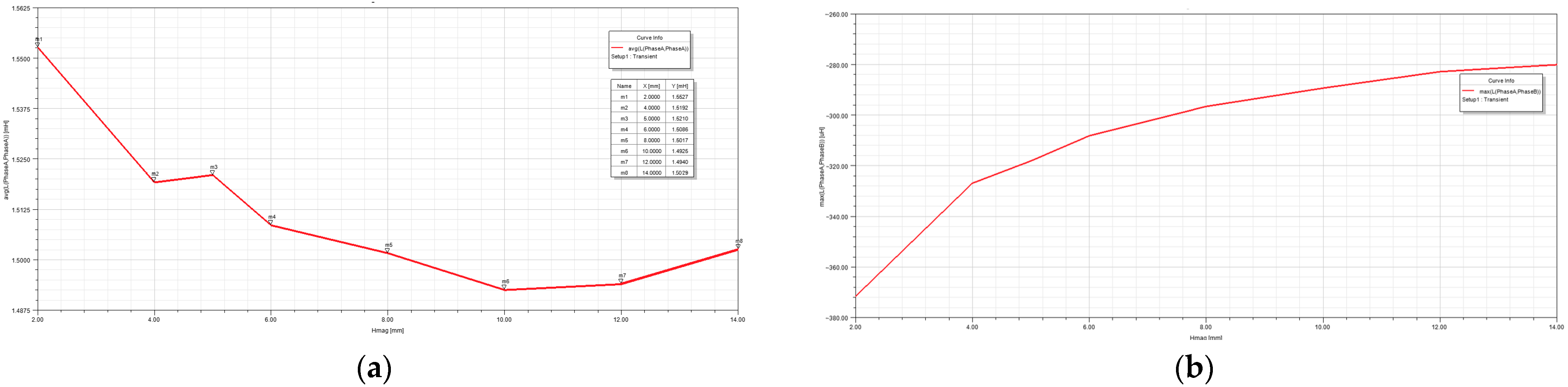
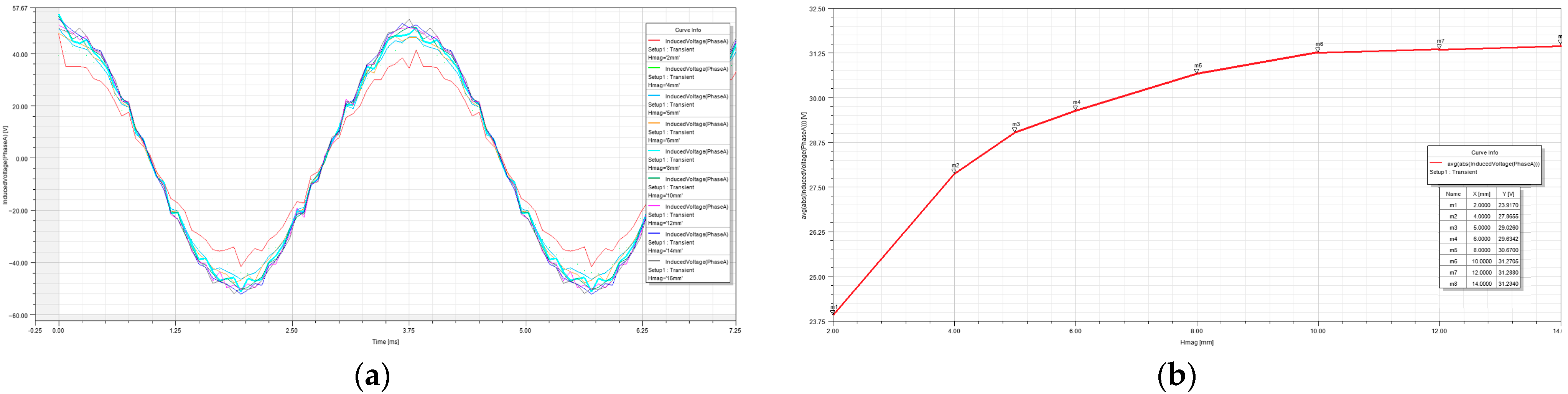
8.2. Influence of the Permanent Magnet Thickness

The optimization of the permanent magnet parameters is an important part of generator optimization, which involves cost and quality considerations [37]. The demagnetization resistance of permanent magnets increases with the increase in thickness, but at the same time, the magnetoresistance is increased. If the permanent magnet thickness is too thin, it is easy to demagnetize, the anti-overload ability is poor and the magnetic flux is lower.
To obtain the influence of the permanent magnet thickness on the performance, the corresponding optimization was carried out. Considering the demagnetization resistance of permanent magnets and the anti-demagnetization ability, the thicknesses were set to 2, 4, 6, 8, 10, 12 and 14 mm.
The self-inductance of phase A at different permanent magnet thicknesses is shown in Figure 14a, and the mutual inductance between phase A and phase B is shown in Figure 14b. The induced electromotive force real-time waveform of phase A for different permanent magnet thicknesses is shown in Figure 15a. The relationship between the permanent magnet thickness and the average induced electromotive force is shown in Figure 15b. The specific values are shown in Table 6.
The stator winding inductance was equal to the sum of the self-inductance and mutual inductance. Table 6 shows that the self-inductance of phase A was much larger than the mutual inductance between phases A and B. Therefore, the effect of mutual inductance could be ignored, and since the three-phase winding was symmetrical, phases B and C were identical to A. Because U = U 0 L I , where U0 is the induced electromotive force, L is the inductance, U is the output voltage and I is the current, it can be seen that the larger the inductance, the smaller the output voltage when the induced electromotive force is the same. Figure 14 shows that when the permanent magnet thickness was less than 10 mm, the self-inductance decreased significantly with the increase in the permanent magnet thickness, and when the permanent magnet thickness was greater than 10 mm, the self-inductance started to increase again. As mutual inductance could be ignored, only the self-inductance was considered when analyzing the effect on inductance. The average induced electromotive force increased with the increase in the permanent magnet thickness, but it almost did not change when the permanent magnet thickness was greater than 10 mm. Therefore, to increase the output voltage, the permanent magnet thickness was selected as 10 mm.

9. Experimental Analysis

In the design, the rated voltage of the generator was 14 V, the rated power was 1000 W and the rated speed was 4000 r/min. According to the analysis results, a prototype with a 2 mm slot width and a 10 mm permanent magnet thickness was made. A photograph of the prototyped generator is shown in Figure 16 and the generator performance test results are shown in Figure 17. The output performance of the novel HEG was tested. The results are shown in Table 7. When the speed changed from 2000 r/min to 4800 r/min and the load power changed from 900 W to 1100 W, the output voltage was stable between 13.5 V and 14.3 V. Therefore, the voltage stabilizing characteristic of the generator was excellent. This performance index conformed to the national standard of GB/T 23923-2009.
The relationship between the excitation current and no-load terminal voltage at different speeds is shown in Figure 18. Figure 18 shows that when the excitation current was −10 A, the no-load terminal voltage was low and very close for different speeds, which indicates that the electromagnetic magnetic field was opposite to the permanent magnetic field at this time; they mutually weakened and the effective synthetic magnetic field was weakened as well. From −5 A to 5 A, the no-load terminal voltage increased linearly with the increase in excitation current. When the excitation current exceeded 5 A, the increase tended to be slow, which indicates that the magnetic circuit tended to be saturated. The results show that the electromagnetic magnetic field could control the permanent magnetic field completely, which was consistent with the simulation results. For the same excitation current, the higher the speed, the higher the no-load terminal voltage. At the rated speed, the maximum no-load terminal voltage was 51.2 V and the minimum was 5.6 V when no voltage regulator was installed. When the excitation current changed, the no-load terminal voltage could change over a wide range, which indicates that the no-load terminal voltage could be effectively regulated by adjusting the excitation current.
Figure 19 shows the excitation current required by an electric excitation generator and the HEG under different loads at the rated speed. When the load power was between 200 W and 800 W, the required excitation current increased linearly, which indicates that its voltage adjustment characteristics were excellent. When the load power was below 400 W, the required excitation current was negative and the electromagnetic field was opposite to the permanent magnetic field. The normal working power region of the HEG was generally above 400 W. In the normal working region, the overall excitation current of the HEG was only about 50% of that of the silicon rectifier generator. Therefore, the HEG could save 50% of energy under the same load condition. The excitation currents of the silicon rectifier generator and HEG were 13.8 A and 8.1 A, respectively, under the rated load. The excitation current can be further reduced by rationally designing the proportion of power occupied by the permanent magnet.
In Figure 20, a comparison of the results shows that the simulation analysis results were close to the actual test results, and the error of the tested and simulated values was within 5%. It was shown that the simulation and optimization method was reasonable, and the generator prototype optimized according to the simulation analysis showed good performance.
Through the experiment, the feasibility of the theoretical analysis and parameter optimization method was further verified, and it has laid a practical foundation for further in-depth research and practical applications of HEGs.

10. Conclusions

To alleviate the current issues of generators for vehicles, a type of novel claw-pole series magnetic circuit HEG is proposed. A magnetic circuit, principle of operation and simulation analyses were conducted. The simulation analysis was consistent with the theoretical analysis, and further experimental verification was carried out. It was shown that the design, analysis and optimization methods adopted in this study were reliable, and the following conclusions can be drawn:
  • In the novel HEG, the permanent magnet and excitation winding share the same magnetic circuit and common excitation, which reduces the excitation loss. The structural parameters were designed based on the theory of a permanent magnet generator and the design method of an electric excitation generator.
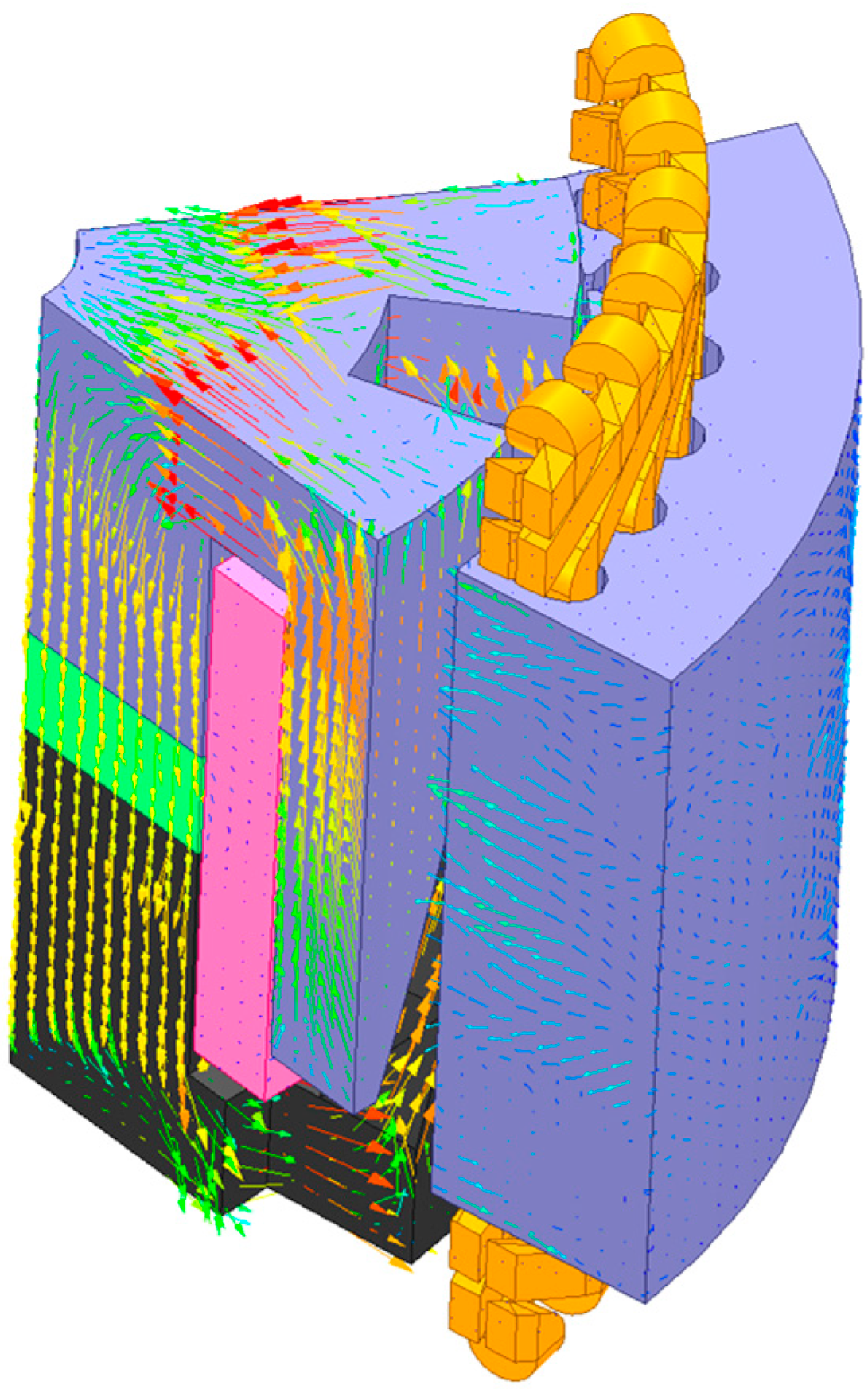
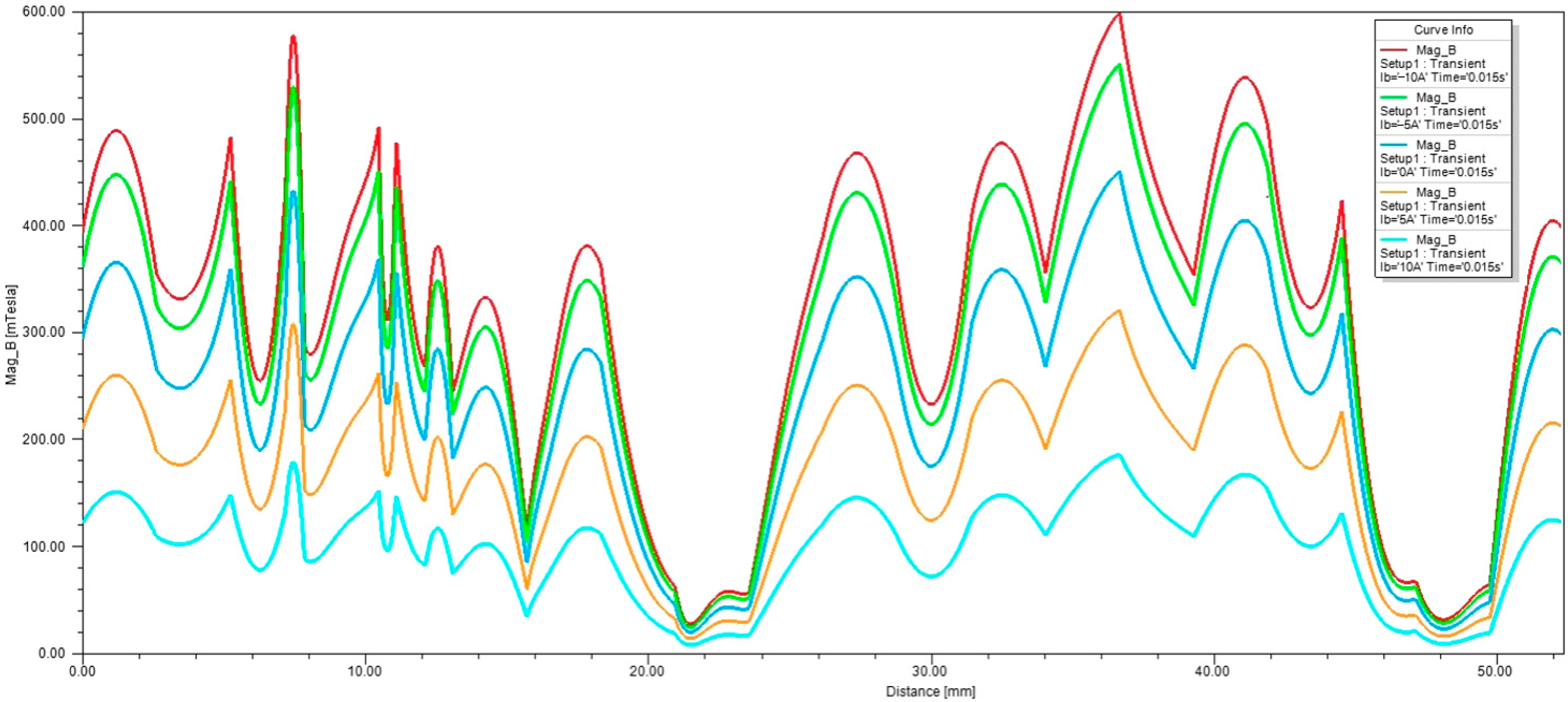
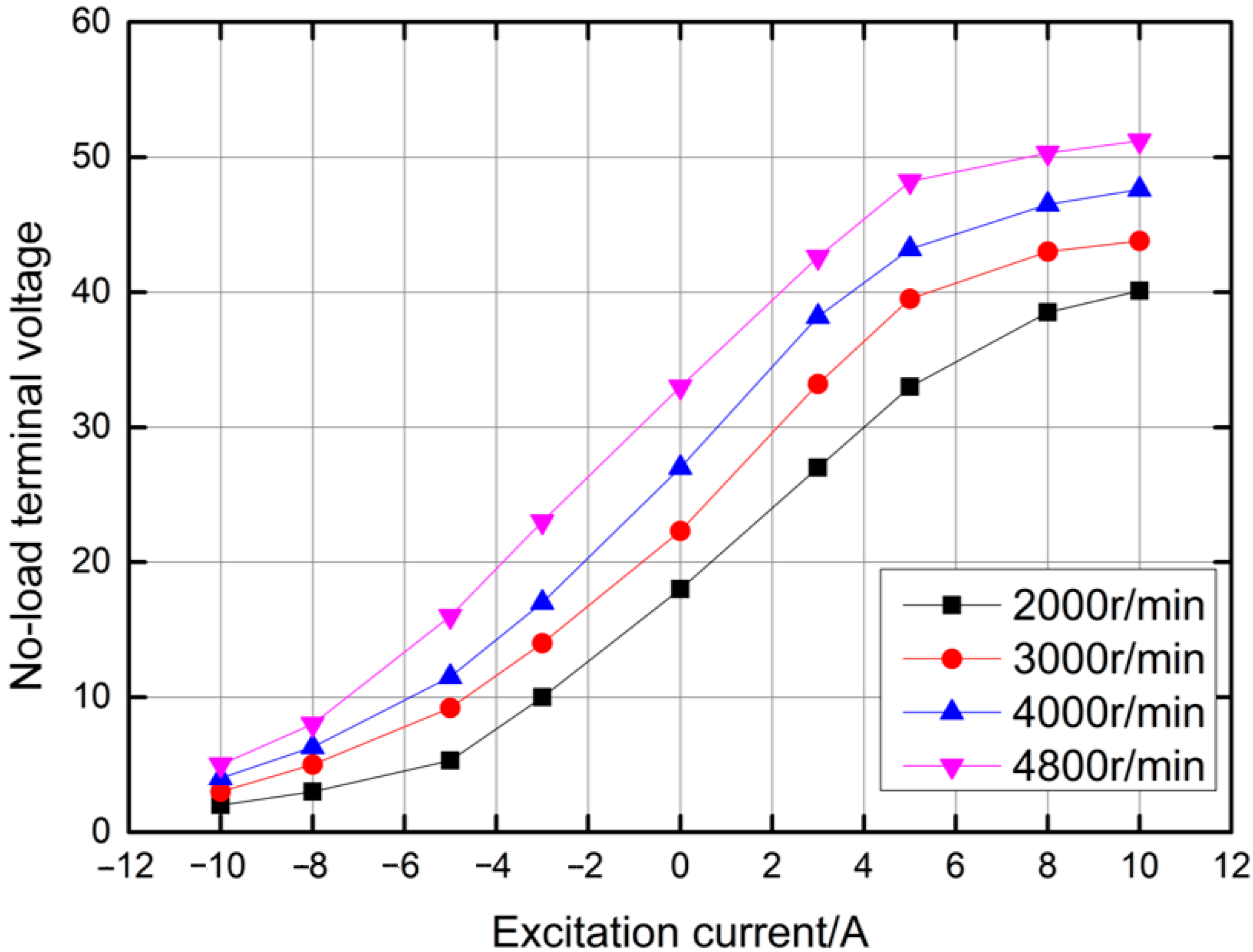
  • A three-dimensional model of a claw-pole series magnetic circuit HEG was established, the no-load characteristics of the generator were analyzed and the magnetic induction in the air gap was obtained when the value of the excitation current in the excitation winding was different. It was shown that the output voltage could be controlled by changing the value and direction of the excitation current.
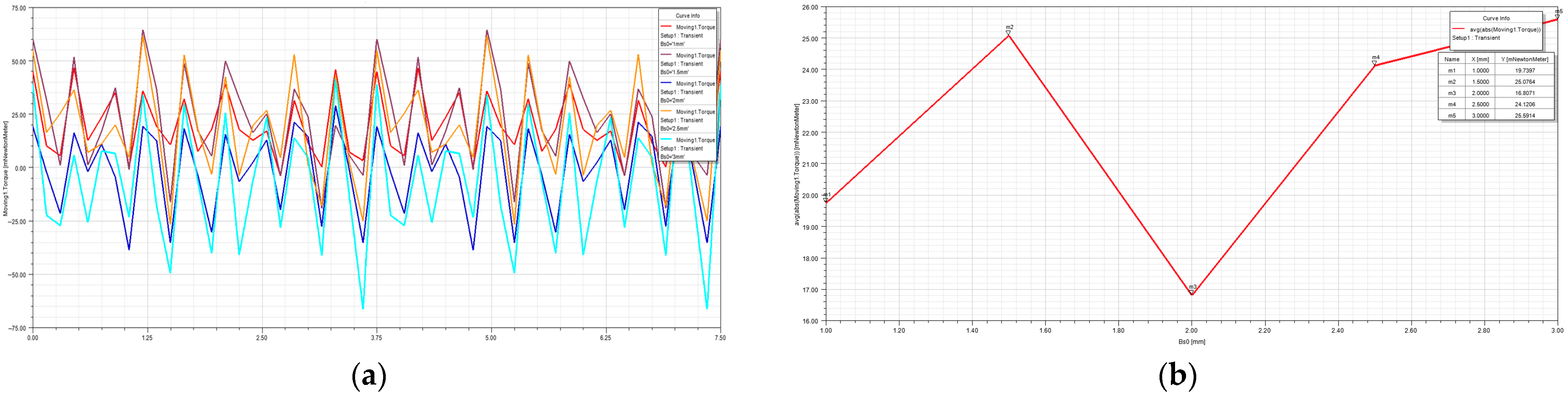
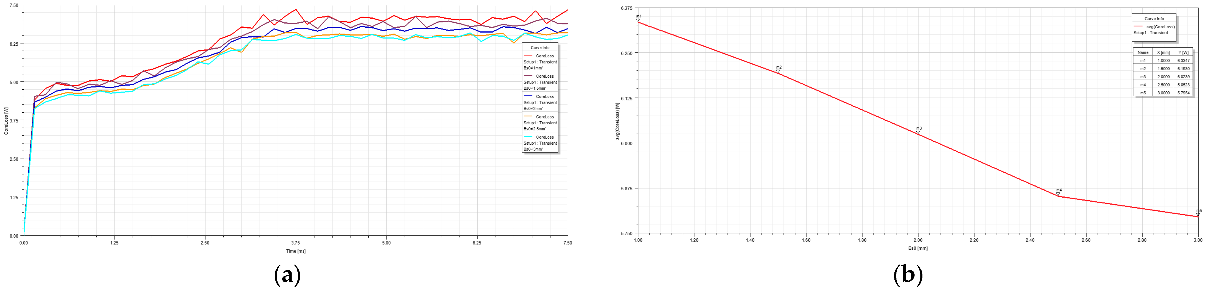
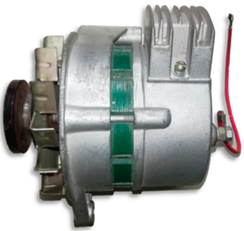
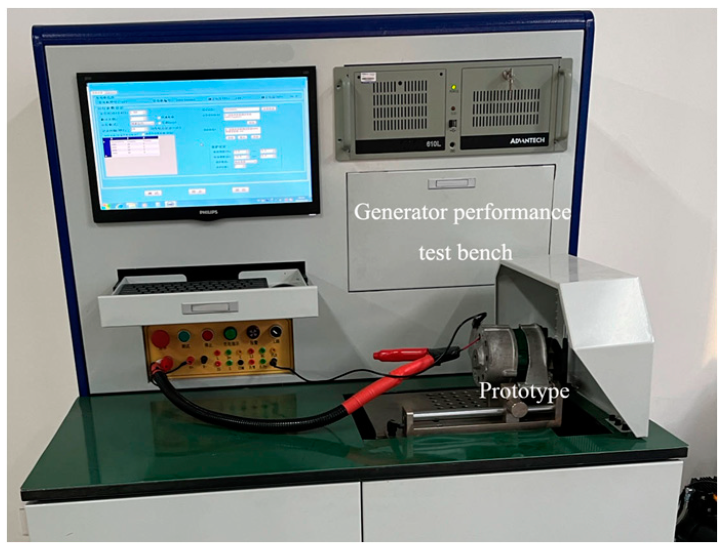
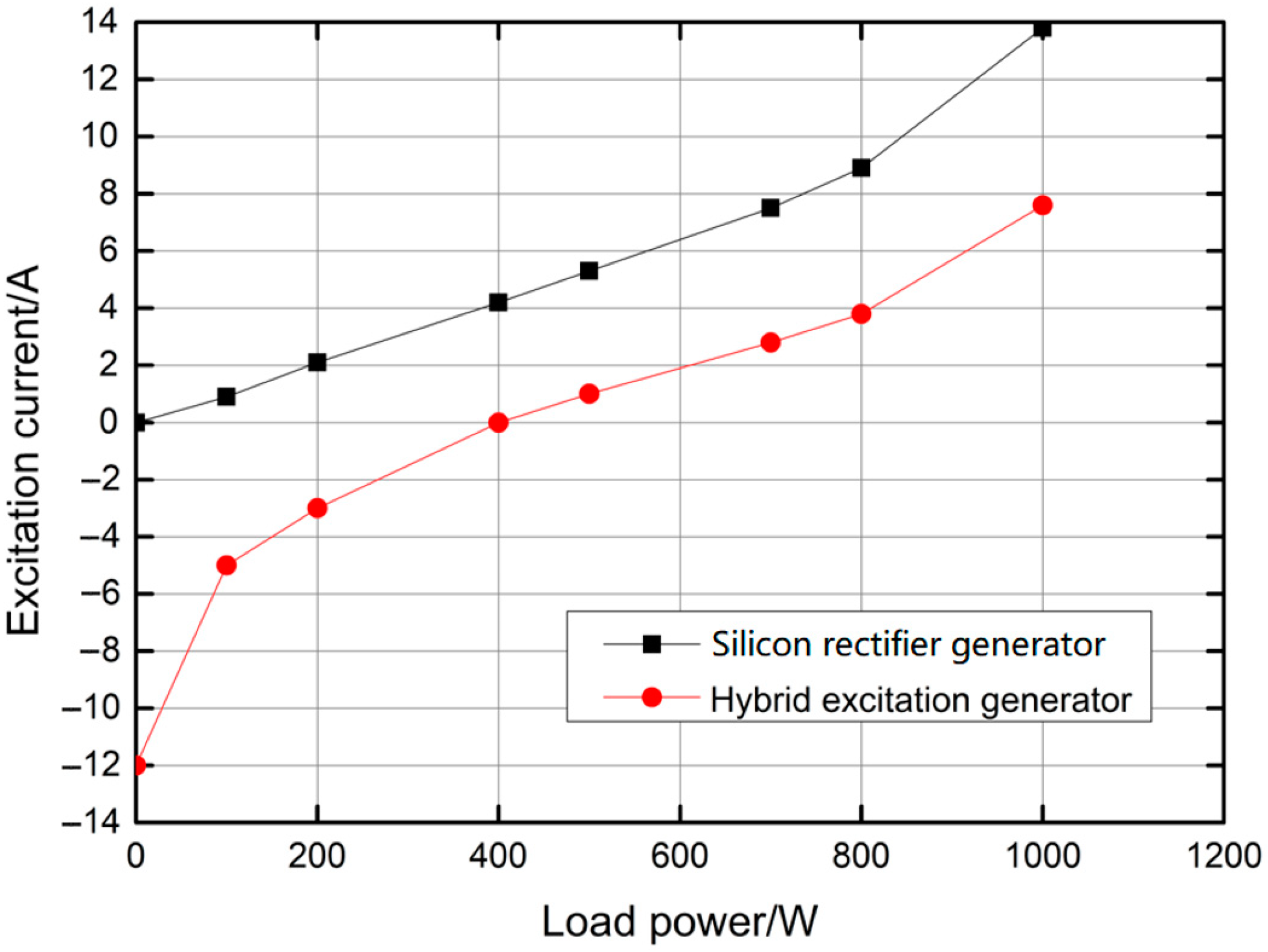
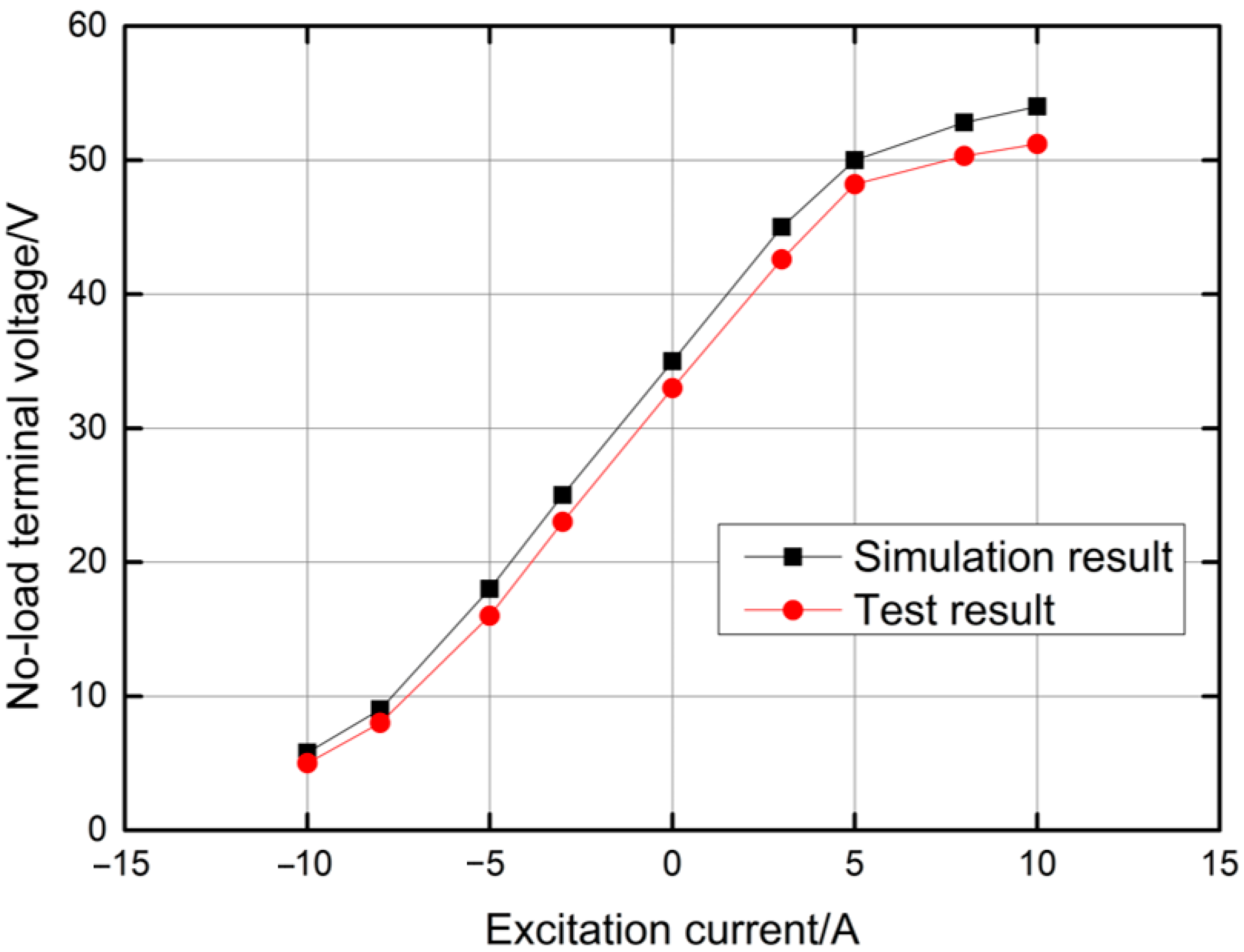
  • The influence of the slot width on the cogging torque, the flux linkage and the iron loss were analyzed, as well as the influence of the permanent magnet thickness on the output voltage. Based on the analysis results, the structural parameters were optimized. According to the results of the optimization analysis, a prototype was made and a test was conducted. The experimental results show that the prototype made according to the optimized results displayed good no-load and output performances, and it saved on excitation consumption compared with a silicon rectifier generator.
In summary, this study provides theoretical and practical support for the development of HEGs for vehicles with a more reasonable structure and higher efficiency.

11. Patents

The research results were awarded a patent for the invention by the China National Intellectual Property Administration, patent number ZL 2021 11534910.4.

Author Contributions

Conceptualization, J.M. and F.G.; methodology, L.W.; validation, J.M., F.G. and S.M.; formal analysis, F.G.; investigation, A.-M.G.; resources, S.M.; data curation, S.Z.; writing—original draft preparation, F.G.; writing—review and editing, J.M.; supervision, J.M.; project administration, J.M.; funding acquisition, S.M. All authors have read and agreed to the published version of the manuscript.

Funding

This research was funded by the National Natural Science Foundation of China (Youth fund project), grant number 52305276, and the Xingtai Youth Talent Plan Project, grant number 2021ZZ034.

Institutional Review Board Statement

Not applicable.

Informed Consent Statement

Not applicable.

Data Availability Statement

The data used to support the findings of this study are included in the article.

Conflicts of Interest

The authors declare no conflicts of interest.

References

  1. Zhang, Z.R.; Wang, D.; Hua, W. Overview and prospect of structure principle, design and operation control technology of hybrid excitation motor. Proc. CSEE 2020, 40, 7834–7850+8221. [Google Scholar]
  2. Prajzendanc, P.; Paplicki, P. Performance evaluation of an axial flux machine with a hybrid excitation design. Energies 2022, 15, 2733. [Google Scholar] [CrossRef]
  3. Geng, H.; Zhang, X.; Si, T.; Tong, L.; Ma, Q.; Xu, M. Analysis of the rotor magnetomotive force of built-in radial Permanent Magnet Generator for Vehicle. Int. J. Rotating Mach. 2021, 2021, 5319615. [Google Scholar] [CrossRef]
  4. Hu, W.; Zhang, X.; Yin, H.; Geng, H.; Zhang, Y.; Shi, L. Analysis of magnetic field and electromagnetic performance of a new hybrid excitation synchronous motor with dual-V type magnets. Energies 2020, 13, 1501. [Google Scholar] [CrossRef]
  5. Wang, G.Y. Current situation and development trend of generator for automobile manufacturing. Mod. Manuf. Technol. Equip. 2017, 23, 146–148. [Google Scholar]
  6. Zhu, X.Y.; Cheng, M.; Zhao, W.X. Review and prospect of hybrid excitation motor technology. Trans. China Electrotech. Soc. 2018, 23, 30–39. [Google Scholar]
  7. Capponi, F.G.; Borocci, G.; Donato, G.D.; Caricchi, F. Flux regulation strategies for hybrid excitation synchronous machines. IEEE Trans. Ind. Appl. 2015, 51, 3838–3847. [Google Scholar] [CrossRef]
  8. Wardach, M. Torque and back-emf in hybrid excited claw pole generator. COMPEL-Int. J. Comput. Math. Electr. Electron. Eng. 2018, 4, 1342–1353. [Google Scholar] [CrossRef]
  9. Malanciuc, A.; Simion, A.; Livadaru, L.; Munteanu, A.; Afanasov, C. FEM-based Analysis of a Hybrid Synchronous Generator with Skewed Stator slots. Adv. Electr. Comput. Eng. 2011, 11, 9–14. [Google Scholar] [CrossRef]
  10. Burkhardt, Y.; Schleicher, K.; Klöpzig, M. A novel hybrid excited synchronous machine for (H)EV applications. In Proceedings of the International Conference on Electrical Machines (ICEM), Berlin, Germany, 2–5 September 2014; pp. 353–359. [Google Scholar]
  11. Hlioui, S.; Vido, L.; Amara, Y.; Gabsi, M.; Miraoui, A.; Lécrivain, M. Magnetic equivalent circuit model of a hybrid excitation synchronous machine. Compel Int. J. Comput. Math. Electr. Electron. Eng. 2008, 27, 1000–1015. [Google Scholar] [CrossRef]
  12. Geng, H.; Zhang, X.; Tong, L.; Ma, Q.; Xu, M.; Zhang, Y.; Wang, L. Performance optimization analysis of hybrid excitation generator with the electromagnetic rotor and embedded permanent magnet rotor for vehicle. IEEE Access 2021, 9, 163640–163653. [Google Scholar] [CrossRef]
  13. Jiang, T.; Zhao, W.; Xu, L.; Ji, J. A novel parallel hybrid excitation field modulated machine with efficient utilization of multi-working harmonics. IEEE Trans. Ind. Electron. 2022, 69, 1177–1188. [Google Scholar] [CrossRef]
  14. Su, W.; Lin, N.; Zhang, X.B.; Wang, D.; Guo, Y.J.; Wei, K. Study on Mathematical Model of interleaved pole Hybrid excitation synchronous generator. Proc. CSEE 2022, 9, 1–11. [Google Scholar]
  15. Zhong, S.H.; Zhu, Z.C. Calculation of stator iron consumption of a Tooth harmonic excitation hybrid excitation generator with a rectifying load. Water Resour. Power 2020, 38, 160–163. [Google Scholar]
  16. Ye, L.Z.; Song, X.J.; Chen, Z. Design and test of slender salient pole hybrid excitation generator for while drilling. J. Electr. Eng. Technol. 2022, 17, 1741–1749. [Google Scholar] [CrossRef]
  17. Geng, H.H.; Zhang, X.Y.; Zhang, Y.F.; Hu, W.; Lei, Y.; Xu, X.; Wang, A.; Wang, S.; Shi, L. Development of brushless claw pole electrical excitation and combined permanent magnet hybrid excitation generator for vehicles. Energies 2020, 13, 4723. [Google Scholar] [CrossRef]
  18. Du, F.; Yao, S.C. Design and Research of a new straight claw Hybrid excitation claw pole Motor. Mech. Electr. Eng. 2019, 36, 539–543. [Google Scholar]
  19. Zhao, W.; Yang, Z.; Liu, Y.; Wang, X. Analysis of a novel surface-mounted permanent magnet motor with hybrid magnets for low cost and low torque pulsation. IEEE Trans. Magn. 2021, 57, 1–4. [Google Scholar] [CrossRef]
  20. Hu, W.; Zhang, X.; Geng, H.; Gao, T.; You, D. Electromagnetic design and flux regulation analysis of new hybrid excitation generator for electric vehicle range extender. J. Electr. Comput. Eng. 2021, 18, 5547517. [Google Scholar] [CrossRef]
  21. Song, I.S.; Jo, B.W.; Kim, K.C. Analysis of an IPMSM hybrid magnetic equivalent circuit. Energies 2021, 14, 5011. [Google Scholar] [CrossRef]
  22. Zhao, C.H. Structure Designing and characteristic study of HECPG with magnetic circuit series connection. Trans. China Electrotech. Soc. 2015, 24, 1–6+12. [Google Scholar]
  23. Geng, W.; Zhang, Z.; Jiang, K. A new parallel hybrid excitation machine: Permanent-magnet variable-reluctance machine with bidirectional field-regulating capability. IEEE Trans. Ind. Electron. 2015, 62, 1372–1381. [Google Scholar] [CrossRef]
  24. Yildiriz, E.; Onbilgin, G. Comparative study of new axial field permanent magnet hybrid excitation machines. Electr. Power Appl. 2017, 11, 1347–1355. [Google Scholar] [CrossRef]
  25. Jia, Z.; Zhao, X.; Deng, X. Design and analysis of a novel hybrid excitation flux reversal machine. Appl. Comput. Electromagn. Soc. J. 2021, 36, 2. [Google Scholar]
  26. Tang, R.Y. Theory and Design of Modern Permanent Magnet Motor, 2nd ed.; Machine Press: Beijing, China, 2019. [Google Scholar]
  27. Yun, D.; Baek, J. Optimal design of a six-Phase permanent-magnet-assisted synchronous reluctance motor to convert into three phases for fault-tolerant improvement in a traction system. Appl. Sci. 2021, 11, 8508. [Google Scholar] [CrossRef]
  28. Liu, Y.; Zhang, Z.; Wang, C.; Gao, H. Optimization and performance improvement of a hybrid excitation synchronous machine with modular magnetic-shunting rotor. IEEE Trans. Ind. Electron. 2020, 67, 4381–4390. [Google Scholar] [CrossRef]
  29. Knypiski, K.; Nowak, L.; Demenko, A. Optimization of the synchronous motor with hybrid permanent magnet excitation system. Int. J. Comput. Math. Electr. Electron. Eng. 2015, 32, 448–455. [Google Scholar] [CrossRef]
  30. Mousavi-aghdam, S.R.; Feyzi, M.R.; Ebrahimi, Y. A new switched reluctance motor design to reduce torque ripple using finite element fuzzy optimization. Iran. J. Electr. Electron. Eng. 2012, 8, 91–96. [Google Scholar]
  31. Liu, J.P.; Cui, T.X. Magnetic field analysis and calculation of the hybrid excitation claw Pole generator Based on Ansoft. Electr. Mach. Technol. 2013, 33, 11–19. [Google Scholar]
  32. Huang, M.; Zhang, Y.; Huang, Q.; Qing, Y.H. Hybrid excitation synchronous machine adaptive speed region control and experimental verification. Int. J. Appl. Electromagn. Mech. 2018, 58, 275–287. [Google Scholar] [CrossRef]
  33. Gu, X.; Zhang, Z.; Sun, L.; Yu, L. Phase displacement characteristics of a parallel hybrid excitation brushless DC generator. IEEE Trans. Energy Convers. 2020, 35, 875–885. [Google Scholar] [CrossRef]
  34. Li, J. Finite-Element analysis of hybrid excitation machine with isolated magnetic paths. Electr. Mach. Control Appl. 2019, 36, 6–9+28. [Google Scholar]
  35. Cao, G.H.; Wang, C.; Zhang, C. Optimization analysis of stator permanent magnet axial flux switching hybrid excitation motor. J. Mach. Des. 2017, 34, 105–112. [Google Scholar]
  36. Ning, Y.H.; Liu, C. Analysis and calculation of electromagnetic and temperature field in a hybrid excitation synchronous generator. Int. J. Appl. Electromagn. Mech. 2016, 3, 435–448. [Google Scholar] [CrossRef]
  37. Yan, A.R.; Zhang, C. New Rare Earth Permanent Magnet Material and Permanent Magnet Motor; Science Press: Beijing, China, 2016. [Google Scholar]
Figure 1. Structure of a claw-pole series magnetic circuit HEG: 1. Stabilizing controller, 2. Rotating shaft, 3. Sliding ring, 4. Rear end cover, 5. Carbon brush, 6. Rear back plate, 7. Magnetic isolation sleeve, 8. Rear claw pole, 9. Armature winding, 10. Stator core, 11. Permanent magnet, 12. Electrical excitation winding, 13. Front claw pole, 14. Front end cover, 15. Fan, and 16. Pulley.
Wevj 15 00139 g001
Figure 2. The magnetic circuit of a HEG. The light blue is a pair of claw pole, the wathet is stator core, the blue is permanent magnet, the green is excitation winding.
Wevj 15 00139 g002
Figure 3. Relationship between the percentage reduced of volume of permanent magnet and power factor.
Wevj 15 00139 g003
Figure 4. Stator punching slot.
Wevj 15 00139 g004
Figure 5. The 1/6 model of a HEG.
Wevj 15 00139 g005
Figure 6. Meshing grid diagram.
Wevj 15 00139 g006
Figure 7. Magnetic field distribution.
Wevj 15 00139 g007
Figure 8. Magnetic density vector distribution. The red is excitation winding, the green is the permanent magnet, the black is the claw pole, the blue above the permanent magnet is the other side of the claw pole, the outer blue is the stator core, and the yellow is the armature winding.
Wevj 15 00139 g008
Figure 9. Magnetic field distribution at different excitation currents: (a) magnetic field distribution when the value of the excitation current is 10 A; (b) magnetic field distribution when the value of the excitation current is 5 A; (c) magnetic field distribution when the value of the excitation current is 0 A; (d) magnetic field distribution when the value of the excitation current is −5 A; and (e) magnetic field distribution when the value of the excitation current is −10 A.
Wevj 15 00139 g009
Figure 10. Magnetic induction in air gap at different excitation currents.
Wevj 15 00139 g010
Figure 11. Cogging torque at different slot widths: (a) the cogging torque real-time waveform with different slot widths; (b) relation between the slot width and peak cogging torque.
Wevj 15 00139 g011
Figure 12. Flux linkage at different slot widths: (a) the flux linkage real-time waveform of phase A at different slot widths; (b) relation between the slot width and average flux linkage.
Wevj 15 00139 g012
Figure 13. Iron loss at different slot widths: (a) the iron loss real-time waveform at different slot widths; (b) relation between the slot width and average iron loss.
Wevj 15 00139 g013
Figure 14. Inductance at different thicknesses of the permanent magnet: (a) the self-inductance of phase A; (b) mutual inductance between phase A and phase B.
Wevj 15 00139 g014
Figure 15. Induced electromotive force at different thickness of the permanent magnet: (a) the induced electromotive force real-time waveform; (b) relationship between the thickness of permanent magnet and the average induced electromotive force.
Wevj 15 00139 g015
Figure 16. The photograph of the generator.
Wevj 15 00139 g016
Figure 17. Generator performance test.
Wevj 15 00139 g017
Figure 18. Relationship between the excitation current and no-load terminal voltage at different speeds.
Wevj 15 00139 g018
Figure 19. The excitation current comparison between the silicon rectifier generator and HEG.
Wevj 15 00139 g019
Figure 20. The result comparison between the test and simulation of no-load terminal voltage under rated power.
Wevj 15 00139 g020
Table 1. Main technical indexes of hybrid excitation generator.
Technical IndexesRated Voltage
(V)
Rated Power
(W)
Rated Speed
(r/min)
Insulation ClassProtection LevelWorking TemperatureOutput Mode
Parameters1410004000EIP23From −40 °C to −75 °CDirect current
Table 2. Parameters of permanent magnet.
Parameters of Permanent MagnetOutside Diameter (mm)Inside Diameter (mm)Thickness
(mm)
Volume
(mm3)
Value60261022,965.04
Table 3. Main parameters of a stator core.
ParametersD
(mm)
D1
(mm)
b0
(mm)
b1
(mm)
t
(mm)
t1
(mm)
R
(mm)
h1
(mm)
hj
(mm)
Value1011452.75.48.83.74.318.94.1
Table 4. Main structure parameters of generator.
ParametersValueParametersValue
Number of pole-pairs6Thickness of claw pole tip (mm)3
Internal diameter of stator core (mm)101Root width of claw pole (mm)10
Outside diameter of stator core (mm)145Root thickness of claw pole (mm)10
Width of claw pole tip (mm)3External diameter of rotor yoke (mm)99
Thickness of permanent magnet (mm)10External diameter of permanent magnet (mm)60
Table 5. Influence of slot width on performance.
Width of Slot
(mm)
Average Cogging Torque (N·m)Average Flux Linkage (Wb)Average Iron Loss
(W)
119.73970.03026.3347
1.525.07640.03006.1930
216.80710.02936.0239
2.524.12060.02915.8523
325.59140.02895.7964
Table 6. Influence of the thickness of permanent magnet on performance.
Thickness of Permanent Magnet (mm)Self-Inductance (mH)Mutual Inductance (mH)Average Induced Electromotive Force (V)
21.5527−0.371623.9170
41.5192−0.326827.8655
51.5210−0.318129.0260
61.5086−0.308129.6342
81.5017−0.296530.6700
101.4925−0.289331.2705
121.4940−0.282831.2880
141.4929−0.280131.2940
Table 7. Experiment results of the voltage stabilizing performance.
Speed (r/min)200040004800
Load power (W)900100011009001000110090010001100
Prototype voltage (V)13.813.713.514.314.114.014.314.214.1
Disclaimer/Publisher’s Note: The statements, opinions and data contained in all publications are solely those of the individual author(s) and contributor(s) and not of MDPI and/or the editor(s). MDPI and/or the editor(s) disclaim responsibility for any injury to people or property resulting from any ideas, methods, instructions or products referred to in the content.

