Abstract
The four-wheel steering distributed drive vehicle is a novel type of vehicle with independent control over the four-wheel angle and wheel torque. A method for jointly controlling the distribution of the wheel angle and torque is proposed based on this characteristic. Firstly, the two-degrees-of-freedom model and ideal reference model of four-wheel steering vehicle are established; then, the four-wheel steering controller and torque distribution controller are designed. The rear wheel angle is controlled by the feedforward controller and the feedback controller. The feedforward controller takes the side slip angle of the center of mass as the control target, and the feedback controller takes the yaw angle as the control target. Torque is controlled by two control layers, the additional yaw moment of the upper layer is calculated by the vehicle motion state and fuzzy control theory, and the lower layer distributes wheel torque through the road adhesion coefficient and wheel load. Finally, a simulation platform is established to verify the effectiveness of the proposed control algorithm.
1. Introduction
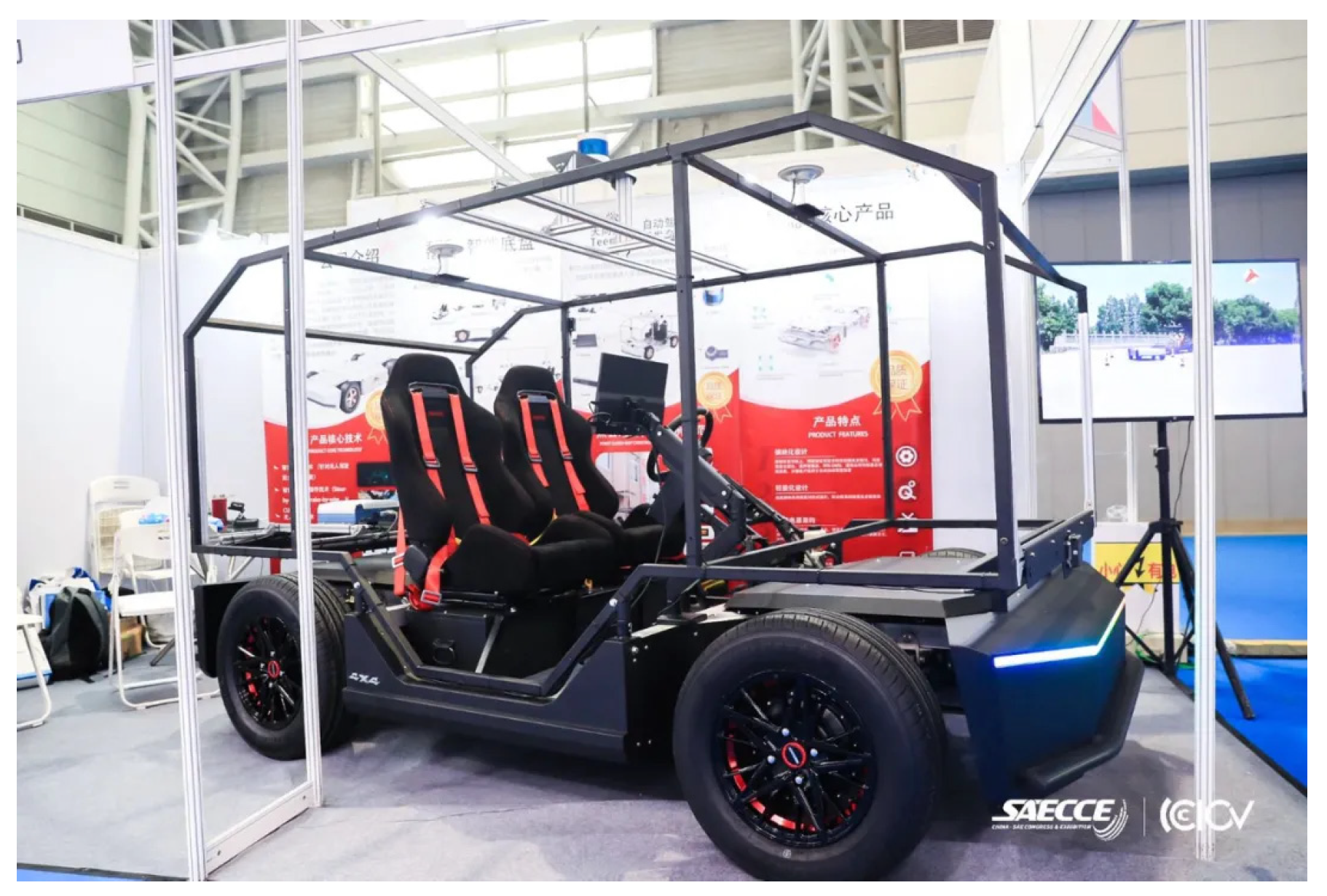
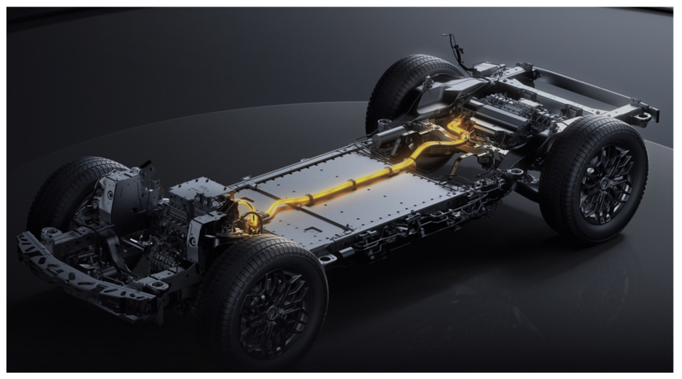
With the rapid advancement of energy storage units and motor power density, significant improvements have been made in the development of electric vehicles. This has brought to light the environmental and energy-related disadvantages of fuel vehicles [1,2]. As drive-by-wire technology continues to mature, there is a growing focus on distributed drive and four-wheel steering technology [3]. Steering-by-wire and distributed drive technology eliminate the need for mechanical transmission modes, thus removing various restrictions imposed by mechanical connections on steering and drive systems. The distributed drive utilizes torque differences among the four wheels to generate additional yaw torque, thereby enhancing vehicle stability. Four-wheel steering vehicles can control the rotation angle of front and rear wheels without changing the longitudinal force of front and rear wheels, and they can control the yaw moment by changing the direction angle of force [4,5]. Effectively leveraging tire longitudinal force and maximizing the benefits of four-wheel steering and distributed drive to further enhance vehicle handling stability has become a challenging focal point within the realm of vehicle chassis control [6]. In 2020, the Teemo four-wheel steering intelligent chassis debuted SAECCE, and in 2022, BYD released the distributed drive car Yang Wang U8 (Figure 1 and Figure 2).

Figure 1.
Teemo four-wheel steering intelligent chassis.

Figure 2.
Yang Wang U8 distributed drive chassis.
At present, a large number of scholars have studied distributed drive and four-wheel steering. Hu [7] proposed an integrated control system for the active front steering and the direct yaw moment control of electric vehicles with a wheel hub based on working area division. The operating areas of the two subsystems are determined according to the driving conditions. Fu [8] proposed a direct yaw moment control method based on sliding mode for electric and hybrid electric vehicles with independent motors. This method employs a novel switching function design to simultaneously track the desired yaw rate and vehicle side slip. Farroni [9] proposed a phase plane to study the influence of tire nonlinearity on vehicle handling, and an active steering controller is designed to enhance the driving stability of the vehicle under extreme working conditions. Zhao [10,11,12] applied a hierarchical structure for stability control, in which the upper controller solves the additional yaw moment by the SMC, LQR or APT method, and the lower controller calculates the wheel driving moment under multiple constraints. Khelladi [13] proposed a hierarchical structure based on the direct yaw moment control method, which combines two different controllers to calculate the globally stable yaw moment, so as to control the yaw rate and vehicle side slip angle. Dai [14] focused on the unmanned chassis with four-wheel drive and steering line control. In order to enhance the multi-direction driving and steering capability of the chassis, a personalized path tracking control strategy based on a reference vector field is proposed. The distributed execution architecture of the unmanned chassis with four-wheel drive and steering line control is established. Ahmadian [15] proposed a multistage control scheme based on active forward steering (AFS) and direct yaw moment control (DYC) to maintain vehicle handling and improve yaw stability. Amro [16] proposed an advanced control method, which integrates several fuzzy controllers to improve the vehicle-handling stability: namely, direct yaw moment control (DYC), active roll moment control (ARC) and active forward steering (AFS). Ref. [17] proposed for the path-tracking problem of unmanned vehicles a robust gain scheduling lateral motion control strategy coordinated by AFS and DYC to improve the stability and maneuverability of the vehicle, so that the vehicle has a good tracking ability. Zhou [18] proposed several changes for electric vehicles where the phase plane is optimized, the stable regions are divided, and different control methods are adopted in different regions, realizing the combined control of active front wheel steering (AFS) and direct yaw moment control (DYC).
All these studies have contributed significantly toward enhancing driving stability; however, it is worth noting that their strategic focus lies on wheel torque and front wheel steering without involving the joint control of wheel torque and four-wheel steering.
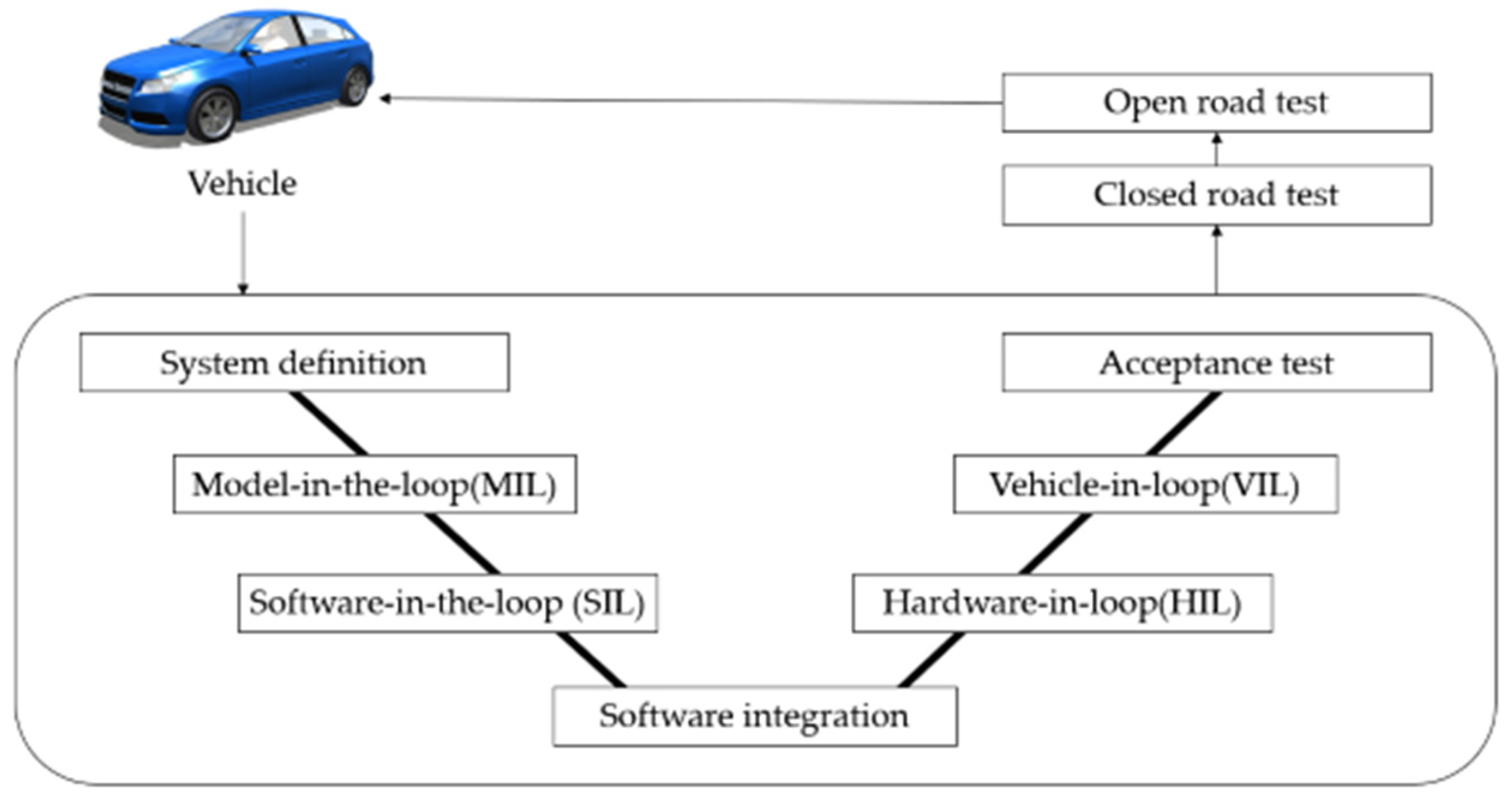
In this paper, the distributed drive vehicle with drive-by-wire four-wheel steering is taken as the research object, and the wheel torque and angle are jointly controlled. The research and development process of the modern vehicle control system is shown in Figure 3. This paper mainly studies the design of model-in-the-loop (MIL) and software-in-the-loop (SIL). Simulation research can greatly reduce the development time and cost in the process of system development, so this paper will conduct simulation analysis to verify its feasibility.
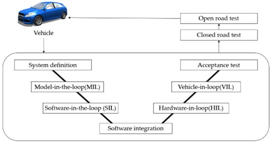
Figure 3.
Development process of modern vehicle control system.
The main contents of this paper can be summarized as follows:
- A control method for the joint control of wheel torque and angle is proposed to improve vehicle stability based on the distributed drive vehicle with drive-by-wire four-wheel steering.
- The mathematical modeling of a four-wheel steering vehicle is established, and proportional feedforward and PID (proportional-integral-derivative control) feedback control is carried out on the yaw rate with the side slip angle of the center of mass as the control objective. Additionally, torque distribution is achieved through the fuzzy control method.
- The angle and torque control strategy is simulated through Matlab/Simulink (R2019b) and Carsim (2020.0) co-simulation analysis to verify its effectiveness.
2. Mathematical Model Construction of Vehicle
2.1. 4WS (Four-Wheel Steering) Vehicle Mathematical Model
The vehicle will be affected by many factors in the actual operation process. This paper only focuses on the vehicle driving stability control and simplifies the vehicle model according to the main research content. The model will be established based on certain assumptions. These assumptions include the vehicle’s movement being restricted to a plane parallel to the ground; neglecting air resistance, changes in wheel vertical load, and the steering system, the front and rear wheel angles are considered as system inputs; it is assumed that the tire’s lateral characteristics fall within the linear range.
The two-degrees-of-freedom (2-DOF) four-wheel vehicle model based on the above assumptions is shown in Figure 4:
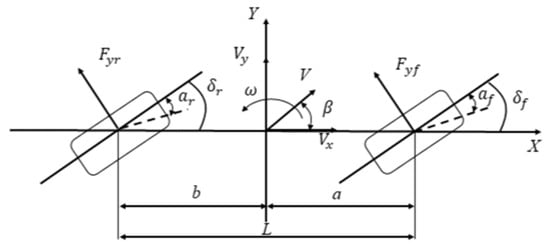
Figure 4.
Two-degrees-of-freedom (2-DOF) four-wheel vehicle model.
Where and are the yaw rate and side slip angle. and are the tire slip angles. Fyf and Fyr denote the front and rear tire lateral forces. and are the desired front and rear wheel angles. a is the distance from the center of mass of the vehicle to the front axle, and b is the distance from the center of mass of the vehicle to the rear axle. L is the vehicle wheelbase. V is the vehicle centroid velocity; Vx and Vy are the components of the vehicle centroid velocity on the X and Y axes, respectively. According to Newton’s second law, the dynamic equation of the vehicle can be derived as
where m is the total mass of the vehicle. Iz is the yaw moment of inertia of the vehicle. Since and are smaller, and are approximately 1. According to the hypothesis of tire side deflection characteristics, the side deflection force and side slip angle of front and rear wheels are calculated; and could be described as
where k1 and k2 are the equivalent tire side stiffness of the front and rear axles. Combining Equations (1) to (3), the dynamic differential equation of the four-wheel steering vehicle model can be described as
The differential equation is converted into the form of a state-space equation, and the yaw rate and the side slip angle of the center of mass are taken as state variables, which can be expressed as . Taking the vehicle front and rear wheel angles and as input variables and the centroid side slip angle and yaw rate as output variables, which can be expressed as , we arranged Equation (4) into an equation with the following state form:
where
2.2. Ideal Reference Model
The ideal reference model is the motion state of the vehicle when it reaches a constant speed and enters a steady state. The ideal yaw rate and side slip angle of the center of mass can be calculated in this state. The motion can be described as follows: with only minimal and negligible front wheel steering, the vehicle moves in a uniform circular motion, where both and are zero [18]. The steady yaw rate can be obtained by combining the 2-DOF four-wheel vehicle model as shown below:
Since the maximum lateral acceleration that the vehicle can achieve is limited by the ground adhesion coefficient, the actual desired yaw rate can be expressed as
At the same time, in order to ensure the stability of the vehicle at high speed, it is assumed that the steady-state side slip angle of the vehicle’s center of mass is 0. Therefore, the expected yaw rate and sides slip angle of the center of mass can be expressed as follows:
where is the road adhesion coefficient, g is the gravitational acceleration, and and are the ideal yaw rate and the side slip angle.
2.3. Drive Motor Model
This paper mainly studies the vehicle dynamics control problem, so according to the output characteristics of the wheel motor, the permanent magnet synchronous motor model is simplified into a second-order system [19]:
where is the target torque calculated by the controller; is the output torque of the wheel hub motor; is the characteristic parameter of the motor, which is related to the internal resistance, self-inductance and mutual inductance of the motor. In this paper, = 0.05.
3. Design of Control Strategy
3.1. The 4WS (Four-Wheel Steering) Vehicle Steering Control Strategy
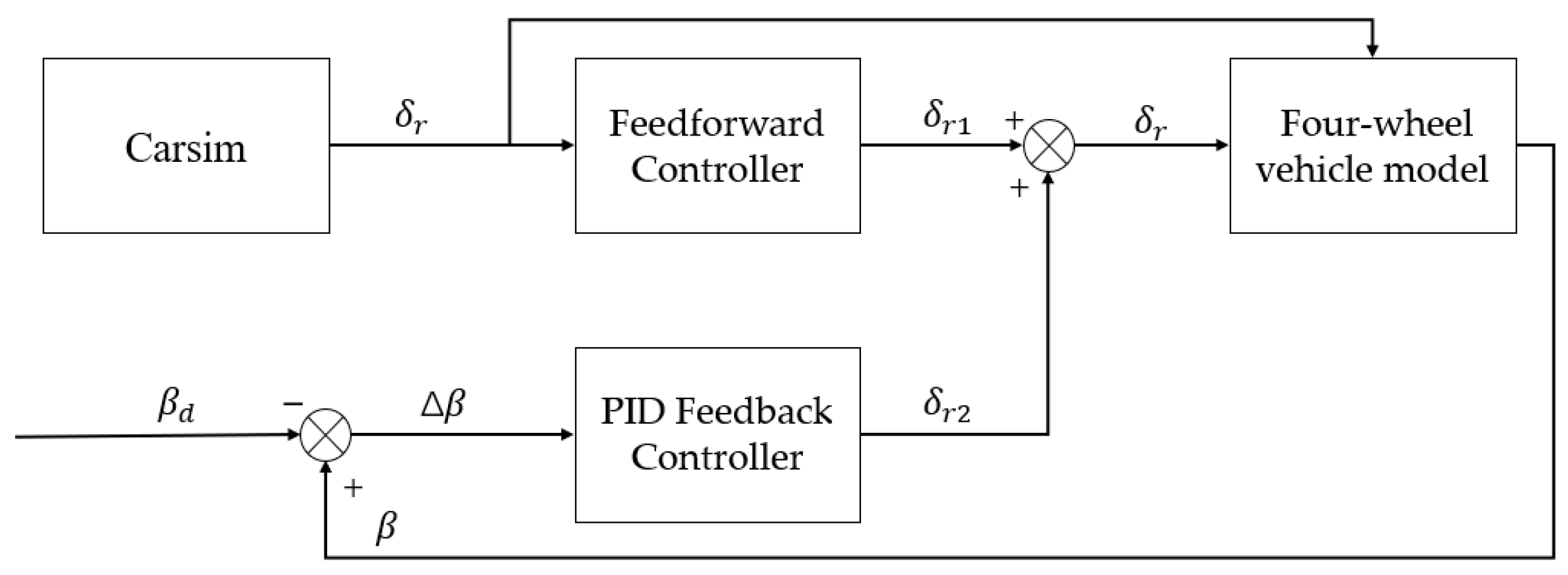
When the side slip angle of the center of mass is maintained near zero, it allows for better completion of pre-viewing the driving trajectory and timely adjustment of the vehicle’s attitude. In this section, a “feedforward + feedback” four-wheel steering control system is designed with the zero centroid side slip angle as the control target. The structure of the control system is shown in Figure 5:
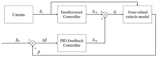
Figure 5.
The 4WS (four-wheel steering) vehicle steering control strategy.
3.1.1. Feedforward Controller
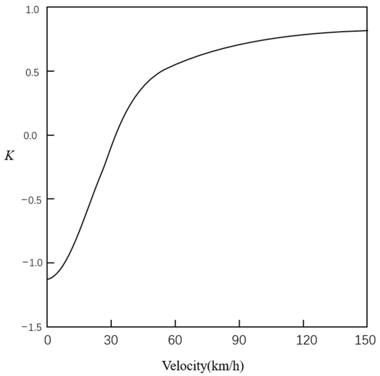
The feedforward control of four-wheel steering adopts a proportional control method for front and rear wheel angles. The objective is to achieve a steady-state side slip angle of zero for the center of mass of the vehicle with the proportional coefficient set as K for the feedforward rear wheel angle and front wheel angle [20].
It can be seen from the above that when the vehicle is in a stable state, the acceleration of the yaw rate = 0, and the control target = 0. By substituting the above conditions into the two-degree-of-freedom model of four-wheel steering as
the curves of the relationship between the front and rear wheel angle ratio and vehicle speed can be obtained from the above equation, as seen in Figure 6.

Figure 6.
Feedforward control angle ratio factor K.
3.1.2. Proportional-Integral-Derivative Feedback Controller
Due to the excessive pursuit of reducing the lateral declination angle of the vehicle’s center of mass, the single feedforward control strategy may lead to dangerous conditions such as side slip or tailspin when the yaw speed of the vehicle reaches a certain limit. This ultimately reduces the vehicle’s high-speed followability and fails to meet stability requirements. To address this issue, this paper proposes adding a PID feedback controller to the existing feedforward control strategy. The input of rear wheel angle under feedback control is as follows:
where KP, KI and KD, respectively, represent the proportional coefficient, integral coefficient and differential coefficient of rear wheel steering feedback, and the rear wheel angle input is the sum of feedforward and feedback.
3.2. Torque Distribution Control Strategy
In this section, the DYC system with an ideal yaw rate as the control target is designed. Based on the layered control strategy, the additional yaw moment is calculated in the upper layer, and the torque distribution of each wheel is controlled in the lower layer. The torque distribution control strategy framework is shown in Figure 7.
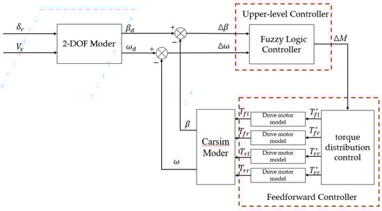
Figure 7.
Torque distribution control strategy diagram.
3.2.1. Upper-level Controller Design
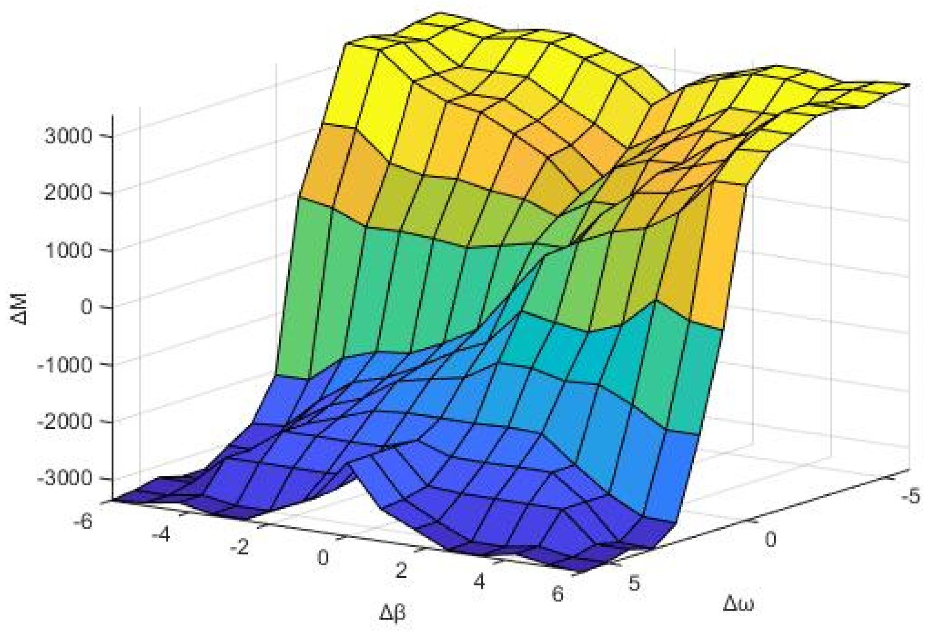
Based on Fuzzy Logic Controller (FLC), a two-dimensional yaw torque fuzzy controller with two inputs and one output is designed. The input values are the yaw rate deviation () and side slip angle deviation (), and the output values are the additional yaw torque (). The fuzzy subset is {PB, PM, PS, ZO, NB, NM, NS}, and the corresponding fuzzy rules are {large, middle, small, zero, negative large, negative medium, negative small}. The control rule fuzzy surface is shown in Figure 8, and the fuzzy control rules are shown in Table 1.

Figure 8.
Control rule fuzzy surface.

Table 1.
The detailed fuzzy control rules.
3.2.2. Lower-Level Controller Design
After calculating the additional yaw moment using the fuzzy controller, torque distribution control will be implemented on all four wheels. To enhance vehicle stability under various operating conditions and meet yaw moment requirements, a wheel torque distribution control method based on vertical load is proposed. Tire adhesion is influenced by the road adhesion coefficient and wheel vertical load. Greater lateral force is generated with a larger vertical load under the same lateral slip angle condition. The front and rear axle loads of the vehicle are
where Fzf and Fzr are the front and rear axle loads of the vehicle, respectively. ax is the longitudinal acceleration, and hg is the height of the center of mass. Torque distribution is carried out according to the front and rear axle load ratio while meeting the total driving force demand. The relationship between the driving force of each wheel as
On the basis of the average distribution of torque, the driving torque of each wheel is distributed according to the proportion of vertical load:
In order to ensure that the torque distribution is in a reasonable range, it is necessary to meet the restrictions on road adhesion conditions and the maximum output torque of the motor, namely:
where Fd is the total driving torque of the vehicle. B is the wheel base. R is the radius of the wheel. Tij is the torque of each wheel. Fzij is the vertical load on the wheel.
4. Simulation Result Analysis
In order to verify the effectiveness of the joint control strategy of four-wheel steering and torque distribution, a joint simulation was carried out by Matlab/Simulink and Carsim, and the feasibility of the control strategy was judged by analyzing the simulation results. The experiment is set up to perform the double lane change (DLC) maneuver with the high adhesion road and a velocity of 80 km/h as well as the on-center steer maneuver test with the low adhesion road and a velocity of 100 km/h. The front-wheel steering vehicle (FWS), four-wheel steering control vehicle (4WS), direct yaw moment control vehicle (DYC) and combined control vehicle (4WS + DYC) were selected for comparison. The vehicle parameters are shown in Table 2.
Table 2.
Vehicle parameters.
4.1. DLC Maneuver on High Adhesion Road
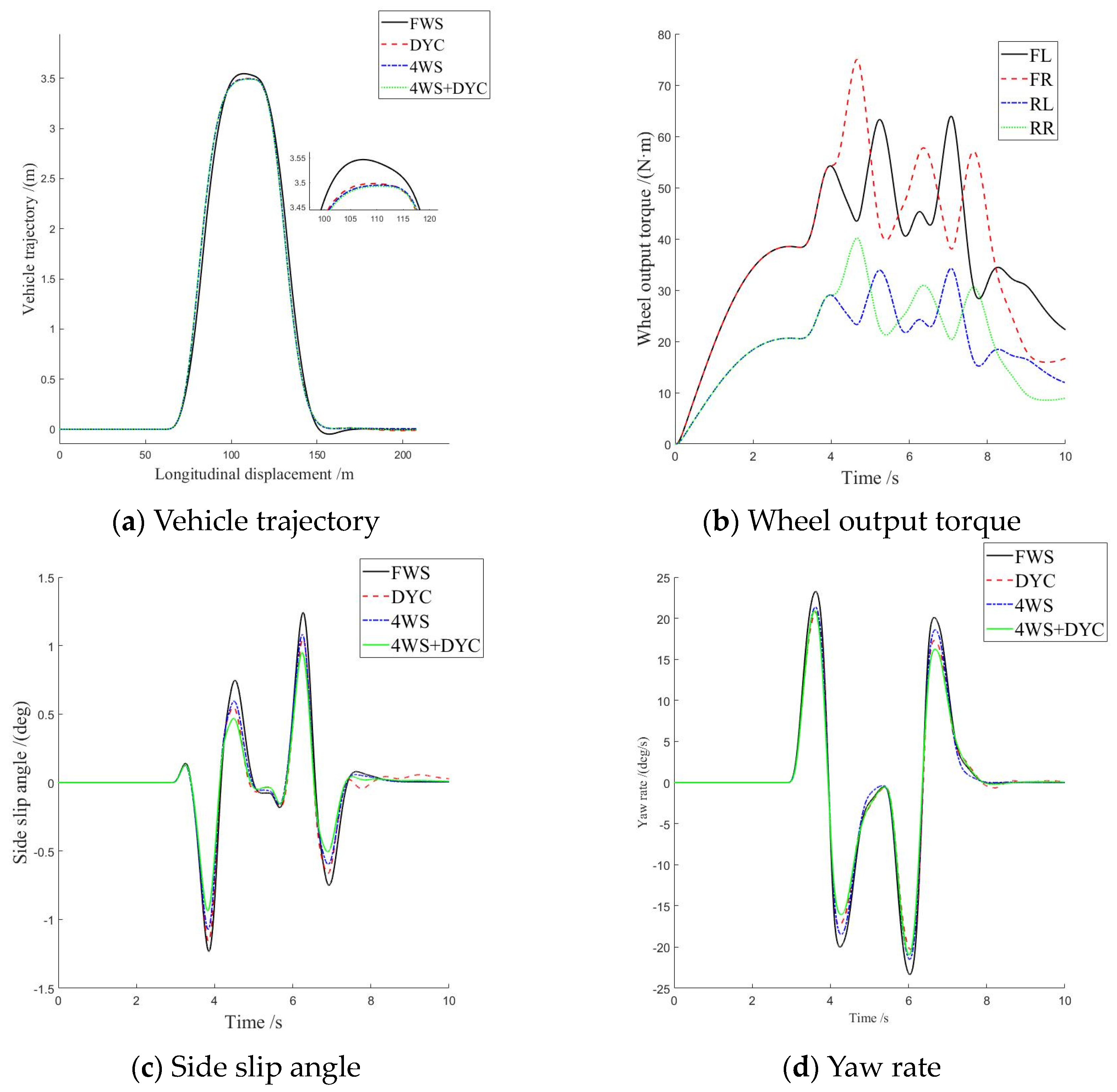
Under the conditions of road adhesion coefficient μ = 0.85 and vehicle speed 80 km/h, the double lane change (DLC) maneuver was tested. Figure 9 indicates the experimental results of DLC maneuvering on high adhesion pavement.
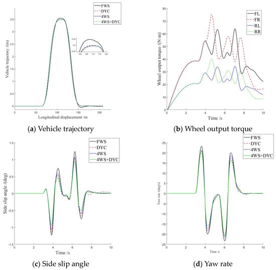
Figure 9.
Experiment results under DLC maneuver on a high adhesion road.
Figure 9a depicts the trajectory of the DLC with four distinct control strategies, demonstrating that the driving trajectory of the vehicle model developed in this study tends to be consistent. The trajectory of FWS exhibits excessive deviation at 90–100 m and obvious deviation at 155 m. On the other hand, 4WS, DYC, and 4WS + DTC exhibit better control over the vehicle trajectory without deviation.
In Figure 9b, the curve diagram illustrates the driving torque of the four wheels. It is evident that the output torque of the front wheel consistently exceeds that of the rear wheel on each side, indicating that our designed control strategy effectively utilizes tire adhesion force with larger axle load and enhances the stability margin for wheels with a lower axle load.
Figure 9c,d reveal consistent trends among all four vehicle models, highlighting significant effects from three control strategies. The peaks of 4WS and DYC are relatively close.
Comparatively, DYC demonstrates a decrease in peak yaw rate by 9.26% and peak centroid side slip angle by 8.14% when compared to FWS. However, instability arises at 7.6 s, leading to significant fluctuations in the centroid side slip angle.
Similarly, for 4WS, there is an observed decrease in the peak yaw rate by 8.33% and peak centroid side slip angle by 7.69%. While stability is maintained, its effect on controlling centroid side slip angle is suboptimal.
In contrast, the combination strategy 4WS + DYC results in a remarkable reduction in the peak yaw rate by 16.67% as well as a substantial decrease in the peak centroid side slip angle by 28.76%. Furthermore, the value tendency toward zero indicates improved maintenance of the vehicle’s driving attitude and body stability.
Therefore, based on the simulation analysis results mentioned above, it can be concluded that under high adhesion road surface conditions, the 4WS + DYC controlled vehicle is capable of enhancing the insufficient steering sensitivity observed in vehicles solely controlled by four-wheel steering. This improvement is achieved through the coordinated control of four-wheel differential torque distribution and a rear wheel angle. Additionally, when compared to vehicles solely controlled by DYC, the 4WS + DYC controlled vehicle exhibits a smaller side slip angle control and higher driving stability. In summary, the overall performance of jointly controlled vehicles surpasses that of vehicles controlled by a single subsystem.
4.2. On-Center Steer Maneuver on Low-Adhesion Road
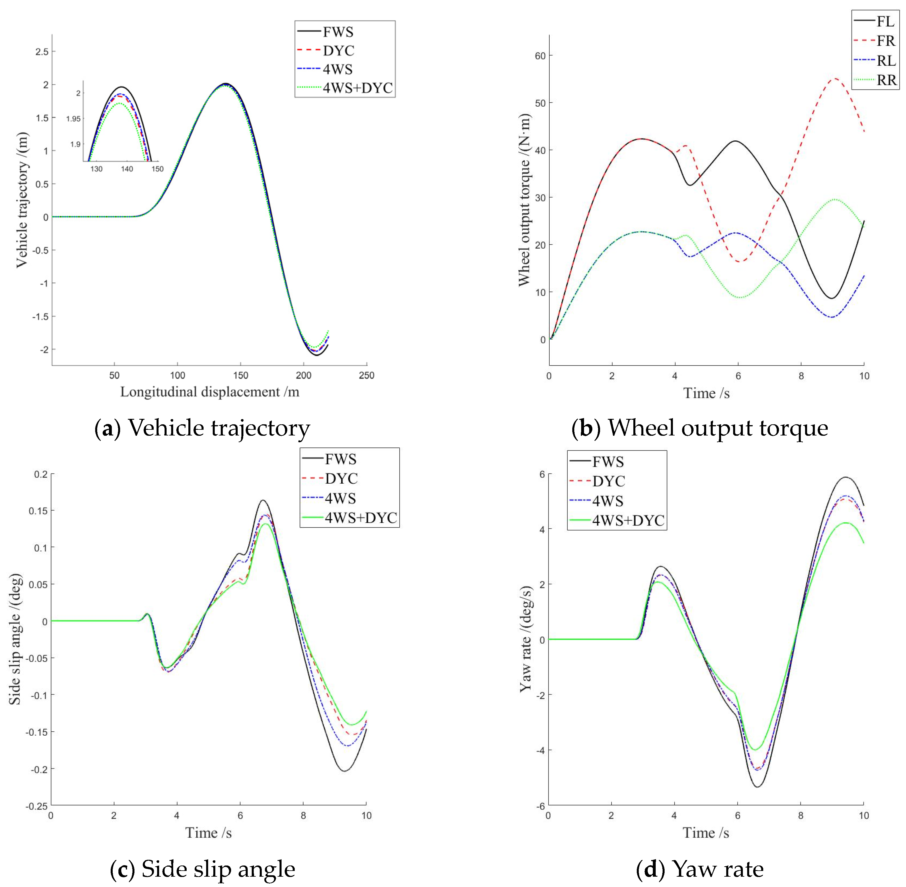
Under the conditions of road adhesion coefficient μ = 0.85 and vehicle speed 80 km/h, the on-center steer maneuver is tested. Figure 10 indicates the experimental results of on-center steer maneuvering on high adhesion pavement.
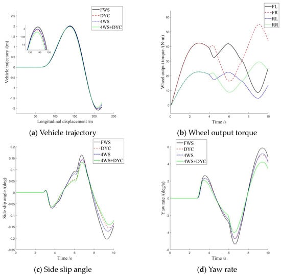
Figure 10.
Experiment results under DLC maneuver on a high adhesion road.
Figure 10a depicts the trajectory of the DLC with four distinct control strategies, demonstrating that the driving trajectory of the vehicle model developed in this study tends to be consistent. The trajectory of FWS exhibits excessive deviation at 200–220 m and obvious deviation. On the other hand, 4WS, DYC, and 4WS + DYC exhibit better control over the vehicle trajectory without deviation.
In Figure 10b, the curve diagram illustrates the driving torque of the four wheels. It is evident that the output torque of the front wheel consistently exceeds that of the rear wheel on each side, indicating that our designed control strategy effectively utilizes tire adhesion force with a larger axle load and enhances the stability margin for wheels with a lower axle load.
Figure 10c,d reveal consistent trends among all four vehicle models, highlighting significant effects from three control strategies. The peaks of 4WS and DYC are relatively close.
Comparatively, DYC demonstrates a decrease in peak yaw rate by 12.48% and peak centroid side slip angle by 22.27% when compared to FWS.
Similarly, for 4WS, there is an observed decrease in peak yaw rate by 14.58% and peak centroid side slip angle by 31.18%. The control effect of yaw velocity of 4WS and DYC is similar, and the control effect of the side slip angle of centroid of 4WS is obviously better than that of DYC.
In contrast, the combination strategy 4WS + DYC results in a remarkable reduction in peak yaw rate by 28.57% as well as a substantial decrease in the peak centroid side slip angle by 35.97%. Furthermore, the value tendency toward zero indicates improved maintenance of the vehicle’s driving attitude and body stability.
Therefore, based on the simulation analysis results mentioned above, it can be concluded that under low adhesion road surface conditions, the 4WS + DYC control vehicle is capable of enhancing the effectiveness of low lateral displacement control under low adhesion road conditions by coordinating four-wheel differential torque distribution and rear wheel angle control. Additionally, when compared to 4WS and DYC alone, the side slip angle and yaw rate of 4WS + DYC can be controlled in a smaller range, resulting in higher driving stability. In summary, the overall performance of an integrated control vehicle is superior to that of a vehicle controlled by a single subsystem.
5. Conclusions
This paper aims at the stability control problem of a distributed four-wheel steering vehicle under the conditions of high and low road adhesion coefficient, respectively, and it improves the lateral stability of the vehicle itself. The four-wheel steering control strategy and torque distribution control strategy are designed, and the vehicle joint control under dual control objectives is realized. The co-simulation model of CarSim and Simulink was built to carry out the simulation experiment. The results show that the proposed control strategy can ensure the trajectory without deviation under the conditions of high and low road adhesion coefficient, and it has better driving stability. However, the drive motor in this paper is a simplified permanent magnet synchronous motor. Under actual conditions, the drive motor will be affected by many factors when executing instructions, thus affecting the response speed and accuracy of the actual control. Subsequently, a more accurate physical model of the drive motor can be further studied. Meanwhile, the research in this paper only verifies and analyzes the control strategy under simulation conditions where the longitudinal speed is expected to remain unchanged. Therefore, the subsequent research can design and study the control strategy of the vehicle under the conditions of acceleration and braking. Due to limitations, the current research in this paper is confined to the offline simulation verification stage. In the future, it is recommended that hardware-in-the-loop testing of the control strategy and verification of the real vehicle environment should be considered for further validation of the control effectiveness.
Author Contributions
Conceptualization, J.Z. (Jiahao Zhang), C.L. and J.Z. (Jingbo Zhao); methodology, J.Z. (Jiahao Zhang); software, J.Z. (Jiahao Zhang), C.L. and J.Z. (Jingbo Zhao); validation, C.L.; investigation, C.L., H.L. and J.Z. (Jingbo Zhao); data curation, J.Z. (Jiahao Zhang); writing—original draft preparation, J.Z. (Jiahao Zhang); writing—review and editing, J.Z. (Jiahao Zhang), C.L., H.L. and J.Z. (Jingbo Zhao); supervision, C.L.; project administration, J.Z. (Jiahao Zhang), H.L. and C.L.; funding acquisition, J.Z. (Jingbo Zhao) and H.L. All authors have read and agreed to the published version of the manuscript.
Funding
This research was funded by the International Joint Laboratory for Operation Safety and Integrated Control of new energy Vehicles, grant number [CZ20230026], the Changzhou Intelligent Networked Vehicle Collaborative Control International Joint Laboratory, grant number [CZ20220030], the Basic Science (Natural Science) Research Project of Higher Education in Jiangsu Province, grant number [22KJA580001], and the National Natural Science Foundation of China, grant number [62273061].
Data Availability Statement
The raw data supporting the conclusions of this article will be made available by the authors on request.
Conflicts of Interest
The authors declare no conflicts of interest.
References
- Serralvo Neto, R.; Palermo, J.B.; Giacomini, R.; Rodrigues, M.; Delatore, F.; Rossi, G.B.; Galeti, M.; Bühler, R.T. Performance Prediction of a 4WD High-Performance Electric Vehicle Using a Model-Based Torque-Vectoring Approach. World Electr. Veh. J. 2023, 14, 183. [Google Scholar] [CrossRef]
- Zhu, S.; Wei, B.; Ping, C.; Shi, M.; Wang, C.; Chen, H.; Han, M. Research on Stability Control Algorithm of Distributed Drive Bus under High-Speed Conditions. World Electr. Veh. J. 2023, 14, 343. [Google Scholar] [CrossRef]
- Zhang, C.; Liu, H.; Dang, M. Robust Shared Control for Four-Wheel Steering Considering Driving Comfort and Vehicle Stability. World Electr. Veh. J. 2023, 14, 283. [Google Scholar] [CrossRef]
- Tahouni, A.; Mirzaei, M.; Najjari, B. Novel Constrained Nonlinear Control of Vehicle Dynamics Using Integrated Active Torque Vectoring and Electronic Stability Control. IEEE Trans. Veh. Technol. 2019, 68, 9564–9572. [Google Scholar] [CrossRef]
- Zhang, L. Research on State Estimation and Torque Vectoring Control of Distributed Drive Electric Vehicles. Ph.D. Thesis, Jilin University, Changchun, China, 2019. [Google Scholar]
- Xing, B. Research on Integrated Control of Four-Wheel Steering and Distributed Drive. Master’s Thesis, Jilin University, Changchun, China, 2023. [Google Scholar]
- Hu, J.; Hu, Z.; Fu, C.; Nan, F. Integrated control of AFS and DYC for in-wheel-motor electric vehicles based on operation region division. Int. J. Veh. Des. 2019, 79, 221–247. [Google Scholar] [CrossRef]
- Fu, C.; Hoseinnezhad, R.; Bab-Hadiashar, A.; Jazar, R.N. Direct yaw moment control for electric and hybrid vehicles with independent motors. Int. J. Veh. Des. 2015, 69, 1–24. [Google Scholar] [CrossRef]
- Farroni, F.; Russo, M.; Russo, R. A combined use of phase plane and handing diagram method to study the influence of tyre and vehicle characteristics on stability. Veh. Syst. Dyn. 2013, 51, 1265–1285. [Google Scholar] [CrossRef]
- Zhao, F.; An, J.; Chen, Q.; Li, Y. Integrated Path Following and Lateral Stability Control of Distributed Drive Autonomous Unmanned Vehicle. World Electr. Veh. J. 2024, 15, 122. [Google Scholar] [CrossRef]
- Ardashir, M.; Hamid, T. A novel adaptive control approach for path tracking control of autonomous vehicles subject to uncertain dynamics. Proc. Inst. Mech. Eng. Part D J. Automob. Eng. 2020, 234, 2115–2126. [Google Scholar]
- Guo, J.; Luo, Y.; Li, K. An adaptive hierarchical trajectory following control approach of autonomous four-wheel independent drive electric vehicles. IEEE Trans. Intell. Transp. Syst. 2017, 19, 2482–2492. [Google Scholar] [CrossRef]
- Khelladi, F.; Orjuela, R.; Basset, M. Direct yaw control based on a phase plan decomposition for enhanced vehicle stability. IFAC Pap. 2019, 52, 7–12. [Google Scholar] [CrossRef]
- Dai, C.; Zong, C.; Zhang, D.; Zheng, H.; Kaku, C.; Wang, D.; Zhao, K. Personalized Path-Tracking Approach Based on Reference Vector Field for Four-Wheel Driving and Steering Wire-Controlled Chassis. World Electr. Veh. J. 2024, 15, 198. [Google Scholar] [CrossRef]
- Ahmadian, N.; Khosravi, A.; Sarhadi, P. Driver assistant yaw stability control via integration of AFS and DYC. Veh. Syst. Dyn. Int. J. Veh. Mech. Mobil. 2022, 60, 1742–1762. [Google Scholar] [CrossRef]
- Elhefnawy, A.; Sharaf, A.; Ragheb, H.; Hegazy, S. Design of an Integrated Yaw-Roll Moment and Active Front Steering Controller using Fuzzy Logic Control. SAE Int. J. Veh. Dyn. Stab. NVH 2017, 1, 270–282. [Google Scholar] [CrossRef]
- Cao, X.; Xu, T.; Tian, Y.; Ji, X. Gain-scheduling LPV synthesis H∞ robust lateral motion control for path following of autonomous vehicle via coordination of steering and braking. Veh. Syst. Dyn. 2023, 61, 968–991. [Google Scholar] [CrossRef]
- Zhou, B.; Liu, Y.Y.; Wu, X.J. Integrated control of active front steering and direct yaw moment. J. Zhejiang Univ. (Eng. Sci.) 2022, 56, 2330–2339. [Google Scholar] [CrossRef]
- Wang, N.; Luo, Z.; Wang, Y.; Yang, B. Coordination control of differential drive assist steering and vehicle stability control for four-wheel-independent-drive EV. IEEE Trans. Veh. Technol. 2018, 67, 11453–11467. [Google Scholar] [CrossRef]
- Yang, F.G. Research on Steering Stability Control of Four-Wheel Independent Four-Wheel Drive Vehicle. Master’s Thesis, Wuhan University of Technology, Wuhan, China, 2023. [Google Scholar]


Disclaimer/Publisher’s Note: The statements, opinions and data contained in all publications are solely those of the individual author(s) and contributor(s) and not of MDPI and/or the editor(s). MDPI and/or the editor(s) disclaim responsibility for any injury to people or property resulting from any ideas, methods, instructions or products referred to in the content. |
© 2024 by the authors. Licensee MDPI, Basel, Switzerland. This article is an open access article distributed under the terms and conditions of the Creative Commons Attribution (CC BY) license (https://creativecommons.org/licenses/by/4.0/).