Article

State-Feedback and Nonsmooth Controller Design for Truck Platoon Subject to Uncertainties and Disturbances

1
School of Mechanical-Electronic and Vehicle Engineering, Beijing University of Civil Engineering and Architecture, Beijing 100044, China
2
China North Vehicle Research Institute, Beijing 100072, China
3
China Merchants Testing Vehicle Technology Research Institute Co., Ltd., Chongqing 401120, China
*
Author to whom correspondence should be addressed.
World Electr. Veh. J. 2024, 15(6), 251; https://doi.org/10.3390/wevj15060251
Submission received: 22 May 2024 / Revised: 3 June 2024 / Accepted: 3 June 2024 / Published: 11 June 2024

Abstract

:
Intelligent truck platoons can benefit road transportation due to the short gap and better fuel economy, but they are also subject to dynamic uncertainties and external disturbances. Therefore, this paper develops a novel robust control algorithm for connected truck platoons. By introducing a linearized expression method of platoon error dynamics based on state measurement, the state feedback mechanism combined with a nonsmooth controller for a truck platoon is proposed in the development of the distributed control method. The state-feedback controller can drive the nominal platoon system to the state of second-order consensus, and the nonsmooth controller counterparts the uncertainties and disturbances. The convergence and string stability of the proposed control algorithm are demonstrated both theoretically and experimentally, and the effectiveness and robustness are also verified by simulation tests.

1. Introduction

1.1. Background of this Research

The increase in the number of vehicles on the road creates heavy burden on road traffic, and increasing concern regarding energy consumption and traffic safety problems [1,2]. Aside from the research on autonomous vehicles, much research effort has been cast to vehicle platoons for their potential in increasing road capacity, reducing energy consumption, and mitigating traffic congestion [3,4,5]. Moreover, vehicle platoons can serve as a stepping stone for improving the autonomous level of intelligent vehicles [6]. A vehicle platoon comprises multiple vehicles arranged in a string formation within a single lane, each with a designated gap between adjacent vehicles. This gap is typically smaller than the distance between independently controlled vehicles, reducing air drag and improving fuel economy [7]. Aiming to leverage the promising benefits of vehicle platoons, different countries and institutes have performed relevant research and even on-road experiments with regard to vehicle platoons [8,9,10].

1.2. Related Works

The existing literatures related to vehicle platoon longitudinal control can be mainly classified into two categories regarding control strategy design: coordinated adaptive cruise control (CACC) [11] and graph-based node network control [12]. In the CACC-like control, the research is basically focused on maintaining the gap between the following vehicle and the immediate predecessor, and the effectiveness of the control algorithm for a platoon consisting of three or more vehicles remains unverified.
The literature on graph-based control can again be categorized into two classes: (1) string-stability-based strategy [13] and (2) consensus-based strategy [14]. String stability refers to the ability of the platoon to attenuate the gap error in the downstream flow of the network. For instance, Dunbar and Caveney [15] utilized MPC-like control to design a distributed vehicle platoon control method to ensure the string stability, in which the dynamic nonlinearity and constraints were taken into consideration. Unlike string stability control, a consensus-based strategy aims to drive the velocity and position of the vehicles in the platoon to reach the consensus state. For instance, Zhang and others [16] established a hierarchical framework to facilitate the design of control algorithm to drive the vehicle platoon to consensus state. There are other studies devoted to the vehicle platoon longitudinal control with a different strategy from those listed above. As an example, Guo and others [17] applied an adaptive triple-step method to devise a control algorithm that copes with the dynamic uncertainties and guarantees the string stability.
In most of the previous research presented above, the double-integrator model is utilized to simulate the vehicle dynamics, lacking consideration of nonlinearity and uncertainty in vehicle dynamics. In addition, the control performance of the controllers designed in these researches is generally verified in an environment lacking certain types of disturbance and uncertainty, rendering these findings less applicable in real-world scenarios.
In spite of the numerous research on vehicle platoon, research on control strategies robust to different types of dynamic uncertainties and external disturbances remains inadequate. Dynamic uncertainties and external disturbances include the aerodynamic drag force, the rolling resistance friction, the effective inertia, and unmodeled dynamics of the vehicle [3]. Lack of consideration of these factors can cause string instability of the vehicle platoon in practice. Some studies are devoted to solving this problem, for instance, Feng and others [18] classified the disturbances and devised different methods to cope with the corresponding kinds; the strategy is quite troublesome and may be sensitive to unexpected uncertainty in application. Guo and others [19] used an adaptive integral-sliding-mode control strategy to neutralize the effect of disturbances; the method can be ineffective or even deteriorate the control performance since the parameter variation of the vehicle was not taken into consideration.
To cope with the dynamic uncertainties and external disturbances existing in vehicle platoon control and to promote sustainable transportation, this paper introduces a novel representation of platoon error dynamics based on the platoon network graph, and proposes a robust distributed control algorithm for truck platoons. In this paper, the network of bidirectional leader topology [20], as illustrated in Figure 1, is utilized to facilitate the design of control algorithms. In the bidirectional topology, every follower can have access to the information of both the leader and the adjacent neighbors.
This paper is structured as follows: First, some mathematical preliminaries such as graph theory and some lemmas are introduced to facilitate the controller design; then, the models considering vehicle nonlinearity and external disturbances will be built and the problem centered on in this paper will be formulated; following that, the control algorithm will be designed with the control performance verified through numerical simulations; finally, the conclusions will be drawn.

2. Mathematical Background

The connected vehicles in a platoon can be treated as nodes in a network, then a graph G n = ( V n , n , A n ) with n denoting the set of nodes V n = { 1 , 2 , n } can be formed to describe the communication among the vehicles. A n = [ a i j ] n × n is the adjacency matrix, and n V n × V n represents the directed set of edges between any two nodes in the graph.
The notation of neighbors of a certain node is symbolized as N i = { i V n : e i j = ( i , j ) n , j i } . A directed spanning tree denotes a subgraph ( V n s , n s ) of graph G n such that V n s = V n and ( V n s , n s ) is a directed tree, which, in the scenario of a vehicle platoon, denotes that the directed information of the leader vehicle is available to every other vehicle node, and each follower node has only one parent node.
For convenience of stating in control algorithm designing, the degree matrix of the graph is defined as D = diag { d 1 , d 2 , , d n } with d i = j N i a i j as the Laplacian matrix of the graph, and G n is defined as L = D A n [21].
Note that G n denotes the network of the n following vehicles; the graph is then augmented as G ¯ n = ( V ¯ n , ¯ n , A ¯ n ) to describe the information flow among graph G n and the leader r . We define the adjacency matrix between nodes in G n and the leader r as B = diag ( b 1 , b 2 , , b n ) , b i = 1 ( i = 1 , , n ) if the directed edge e r i = ( r , i ) r , otherwise, b i = 0 . Obviously, V ¯ n = { r , 1 , 2 , n } , ¯ n = n r . And if the leader is included in the graph, then the Laplacian matrix is denoted as L r .
Next, we present a lemma proposed in a previous study to facilitate the design and stability analysis of the controller.
Lemma 1 [22]. 
Suppose in the extended graph  G ¯ n  of a graph   G n , a directed spanning tree exists with the root node being the leader, then matrices  L ¯ = L + B , and the addition of the Laplacian matrix and the adjacency matrix, is invertible.
Definition 1 [23]. 
Suppose an interconnected system:
x ˙ i = f ( x i , x i 1 , , x 1 )
where  i V n x i n f : n × × n n   and  f ( ) = 0  with  x i , x i 1 , , x 1 = 0 , then the system is string stable, if given any  ϖ > 0 , there exists a  ε   such that  x i ( 0 ) < ε sup i x i ( ) < ϖ .

3. Model Description and Problem Formulation

Supposing the string-formed vehicles move along a straight line through the vehicle-to-vehicle (V2V) communications; it is assumed that a GPS signal is available to every vehicle in the platoon, then the absolute position and longitudinal velocity can be measured and communicated in the network.

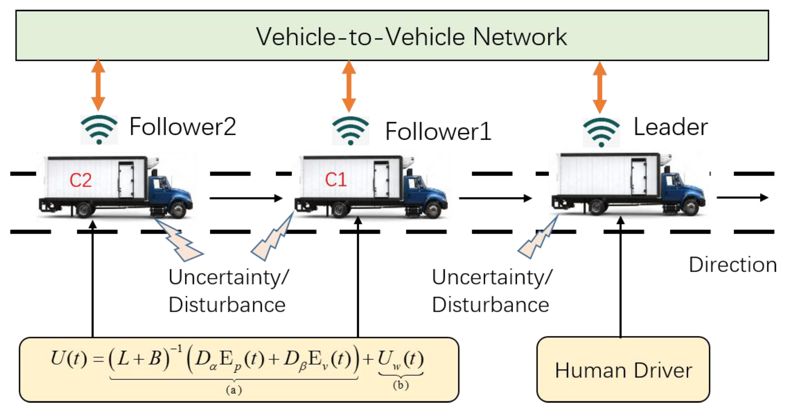
3.1. Vehicle Dynamics Modeling

The dynamics of the i th vehicle considering dynamic uncertainty and external disturbances can be expressed as [24]
{ p ˙ i ( t ) = v i ( t ) v ˙ i ( t ) = f ( t , v i ( t ) ) + d i ( t ) + u i ( t )
where p i ( t ) , 1 i N , and v i ( t ) denote the longitudinal position and longitudinal velocity of i th vehicle at time t ; d i ( t ) is the external disturbance including parameter uncertainties; u i ( t ) is the to-be-designed control input. The nonlinear function f ( t , v i ( t ) ) is given as
f ( t , v i ( t ) ) = c f i v i 2 m + g r o
where r o is the tire rolling resistance, c f i v i 2 denotes the force caused by air resistance in the test environment, m is the mass of the vehicle; normally, the air drag coefficient c f i varies with the vehicle gap h g between the ego vehicle and the preceding vehicle [17], expressed as
c f i = c d / { 1 [ c d 1 / ( c d 2 + h g ) ] }
where c d , c d 1 , and c d 2 are all empirically selected coefficients. Similarly, the dynamics model for the leader r can be described as
{ p ˙ r ( t ) = v r ( t ) v ˙ r ( t ) = f ( t , v r ( t ) ) + d r ( t ) + u r ( t )
where p r ( t ) , v r ( t ) , f ( t , v r ( t ) ) , d i ( t ) , and u r ( t ) denote the position, velocity, nonlinear dynamics, external disturbances, and control input of the leading vehicle.

3.2. Definition of Second-Order Consensus

Consider an extended network G ¯ with arbitrary bounded initial states p ( 0 ) , v ( 0 ) n , if under the designed control input U ( t ) = [ u 1 ( t ) , u 2 ( t ) , , u n ( t ) ] n there exists a limited settling time T > 0 such that lim t T | p i ( t ) + i h p r ( t ) | = 0 , lim t T | v i ( t ) v r ( t ) | = 0 , where h is the designated vehicle-to-vehicle gap, and p i ( t ) + i h = p r ( t ) , v i ( t ) = v r ( t ) , t T , i = 1 , 2 , n , then the platoon can reach second-order consensus in a finite time [25].

4. Robust Controller Design

The dynamics of the following vehicles are subject to nonlinear resistance and uncertain disturbance. Thus, the designed control algorithm needs to drive the network to second-order consensus while being robust to dynamic uncertainties and external disturbances. The overall control algorithm design is illustrated in Figure 2.

4.1. Platoon Error Dynamics Model

First, a novel second-order platoon error dynamics model will be built to facilitate the controller design. For the i th vehicle in graph G , based on the local states information it has access to, we define the position tracking error e p i ( t ) and the velocity tracking error e v i ( t ) as
{ e p i ( t ) = j N i a i j ( p i p j + ( i j ) h ) + b i ( p i p r + i h ) e v i ( t ) = j N i a i j ( v i v j ) + b i ( v i v r )
For convenience, we let E p ( t ) [ e p 1 , e p 2 , , e p n ] T n , E v ( t ) [ e v 1 , e v 2 , , e v n ] T , D ( t ) [ d 1 ( t ) , d 2 ( t ) , , d n ( t ) ] T , U ( t ) [ u 1 ( t ) , u 2 ( t ) , , u n ( t ) ] T n , L = [ l i j ] n × n and F ( t , E v ( t ) ) = [ f ( t , v 1 ( t ) ) , f ( t , v 2 ( t ) ) , , f ( t , v n ( t ) ) ] n ; then, based on (3) and (4), the tracking errors in (6) can be rewritten as
{ E ˙ p ( t ) = E v ( t ) E ˙ v ( t ) = ( L + B ) ( F ( t , E v ( t ) + D ( t ) ) B ( 1 n ( f ( t , v r ( t ) ) + d r ( t ) ) ) + ( L + B ) U ( t )
Remark 1. 
The error dynamics model expressed in (6) consists of the interconnection of vehicle nodes in graph  G , and the convergence of the error implies the second-order consensus of the platoon. Consequently, various control algorithms can be designed for the system effortlessly.

4.2. Derivation of the Controller

Considering the nonlinearity and the disturbances in vehicle dynamics, the control algorithm can be constructed as
U ( t ) = ( L + B ) 1 ( D α E p ( t ) + D β E v ( t ) ) ( a ) + U w ( t ) ( b )
where D α = d i a g ( α ) and D β = d i a g ( β ) are diagonal matrices of constants α and β , respectively. In (7), part (a) is used to drive the platoon to second-order consensus, and the to-be-designed part (b) is designed to counterpart the uncertainties and external disturbances.
To represent the dynamic uncertainty explicitly, we divide the nonlinear dynamics f ( t , v i ( t ) ) into nominal term f n ( t , v i ( t ) ) and uncertain term f u ( t , v i ( t ) ) , as
f ( t , v i ( t ) ) = f n ( t , v i ( t ) ) + f u ( t , v i ( t ) )
The nonlinear dynamics term is then rewritten as
F ( t , E v ( t ) ) = F n ( t , E v ( t ) ) + F u ( t , E v ( t ) )
For simplicity, we omit the parenthesis in the symbols, such as F n F n ( t , E v ( t ) ) . Then by defining a new state variable ξ = [ E p T ( t ) , E v T ( t ) ] T , and combining the controller designed in (7), the new error dynamics model can be constructed as
ξ ˙ = A ξ ξ + B ξ U w ( t ) + D ξ + N ξ
with
A ξ = [ 0 n × n I n D α D β ] ,   B ξ = [ 0 n × n 0 n × n 0 n × n L + B ] ,   D ξ = [ 0 n × 1 ( L + B ) ( D + F u ) B 1 n ( f u ( t , v r ) + d r ) ] ,
N ξ = [ 0 n × 1 ( L + B ) F n B 1 n f n ( t , v r ) ] ,   U w = [ 0 n × 1 u w ] ,
where 0 a × b , with constants a , b [ 1 , n ] , denotes a full zero a × b matrix.
Before we proceed to the control algorithm, an assumption about the boundedness of nonlinearity and uncertainty shall be made.
Assumption 1. 
Suppose for a multinode system with the dynamics of the nodes described by (3) and (5), there exist two positive constants  f 1   and  d 1   such that, for any bounded variable  x ( t ) , v ( t )  and  t > 0 , the inequalities  | f u ( t , v ( t ) ) | < f 1  and  sup t > 0 { | d 1 ( t ) | , | d 2 ( t ) | , , | d n ( t ) | , | d r ( t ) | } d 1 hold.
Then, based on the system represented by (10), the auxiliary term of the controller can be designed as follows:
u w ( t ) = ( L + B ) 1 [ λ sgn ( E v ( t ) ) | E v ( t ) | κ N ξ ] ,
where λ > 0 , 0 < κ < 1 are constants, and | E v ( t ) | 2 denotes a vector consisting of the square of each element of | E v ( t ) | .
Next, we present a theorem regarding the stability analysis of the proposed controller.
Theorem 1. 
Suppose Assumption 1 holds, and a directed spanning tree in the extended network  G ¯ n  exists with the root node being the leader, then position errors of vehicles in graph  G  will reach consensus in finite time by the proposed controller in (7) and (11), with the velocity error of each vehicle  i  bounded in  Q i , where
Q i = { e v i : | e v i | ( d 1 + δ λ ) 1 / κ } ,
and  δ > 0  can be arbitrarily small.
Proof. 
Considering the linear presentation of the system in (11) and based on the linearization property [26], the system (10) can be divided into the sum of the nominal system
ξ ˙ n = A ξ ξ n
and the disturbance system
ξ ˙ u = A ξ ξ u + B ξ U w ( t ) + D ξ + N ξ
Note that the disturbance will not affect the positions of vehicles explicitly; then, combining the controller designed in (11), the system (14) can be dimension-reduced as
E ˙ v ( t ) = λ sgn ( E v ( t ) ) | E v ( t ) | κ + d
where
d = ( L + B ) ( D + F u ) B 1 n ( f u ( t , v r ) + d r ) .
First, we demonstrate the convergence of the disturbance system. We define a Lyapunov function for vehicle i as V ( e v i ) = e v i 2 / 2 , then combining the distributed form of (15), we have the first derivative of V ( e v i ) with regard to time:
V ˙ ( e v i ) = e ˙ v i e v i = λ e v i sgn ( e v i ) | e v i | κ + e v i d i ( λ | e v i | κ d 1 ) | e v i |
where d i is the i th element of d . Then, for an arbitrary e v i Q i , we have
| e v i | > ( d 1 + δ λ ) 1 / κ
and
λ | e v i | κ d 1 > δ .
Then, based on (16), we have
V ˙ ( e v i ) < δ | e v i | < 0 .
The convergence of the system (14) is related to the initial state, e v i ( 0 ) . If e v i ( 0 ) locates outside of Q i , expressed as e v i ( 0 ) Q i , then a finite time t 1 exists that e v i ( t 1 ) Q i with Q i denoting the border of Q i . If e v i ( 0 ) locates inside of Q i , expressed as e v i ( 0 ) Q i , then we can conclude that the consensus is achieved. Otherwise, there exists a possibility that the states drift outward Q i , then a finite time t 1 must exist such that e v i ( t 1 ) Q i due to the continuity of the states. Then, we only need to prove that e v i ( t ) Q i with t [ t 1 , + ) . By setting
Ψ i = inf e v i ( t ) Q i | e v i ( t ) |
and
ϕ i = λ | e v i | 1 + κ d 1 | e v i | .
we can obtain
Ψ i = ( d 1 + δ λ ) 1 / κ
and
ϕ i = δ ( d 1 + δ λ ) 1 / κ
It can be easily deduced that ϕ i > 0 .
Then, for e v i ( t ) Q i , we have
V ˙ ( e v i ) δ < 0
Then, based on the results presented by (19) and (24), it can be drawn that a finite time t 1 exists such that e v i ( t 1 ) Q i for states located outside of Q i , and there also exists a finite time t 2 such that e v i ( t ) Q i with t [ t 1 , t 2 ) . In conclusion, e v i will always be driven into Q i upon arriving at the boundary.
As the bound of Q i can be small enough in value by tuning δ and λ , the effect of disturbances can be eliminated to a large extent.
Next, we present proof that the system (10) can be stabilized by the state-feedback controller.
First, applying the error dynamics in (6) and eliminating the disturbance terms, the nominal system (10) combined with the dynamics of the leader can be rewritten as
[ p ˙ v ˙ ] = Θ ( t ) [ p v ]
where p [ p r , p 1 , p 2 , , p n ] T n + 1 , v [ v r , v 1 , , v n ] T , and
Θ ( t ) = [ 0 I n + 1 α L r β L r ]
The eigenvalues of Θ ( t ) can be obtained by solving the characteristic equation det ( λ I 2 n Θ ( t ) ) = 0 We have the following equation:
det ( λ I 2 n + 2 Θ ( t ) ) = det [ λ 2 I n + 1 + ( α + λ β ) L r ]
and
det [ λ I n + 1 + L r ] = i = 1 n + 1 ( λ μ i )
Then, integrating (28) and (29), we have
det [ λ 2 I n + 1 + ( α + λ β ) L r ] = i = 1 n + 1 [ λ 2 ( α + λ β ) μ i ]
The characteristic equation can be solved as [27]
λ i ± = β μ i ± β 2 μ i 2 + 4 α μ i 2
From (31), we know that L r has exactly one zero eigenvalue, when Θ ( t ) has two zero eigenvalues. Denoting l [ l a T , l b T ] T , where l a T , l b T n + 1 , is an eigenvector of Θ ( t ) with zero eigenvalues, we have
Θ l = [ 0 I n + 1 α L r β L r ] [ l a l b ] = [ 0 n + 1 0 n + 1 ]
From (32), the relation l b = 0 n + 1 and L r l a = 0 n + 1 can be obtained. Further, we can conclude that the algebraic multiplicity for zero eigenvalue of Θ ( t ) equals two, whereas the geometric multiplicity equals one.
As the matrix Θ ( t ) can be expressed with Jordan canonical form,
Θ ( t ) = P J P 1 = [ ω 1 ω 2 n + 2 ] T [ 0 1 0 1 × 2 n 0 0 0 1 × 2 n 0 2 n × 1 0 2 n × 1 J ] [ ρ 1 T ρ 2 n + 2 T ] T
where ω j 2 n + 2 , j = 1 , , 2 n + 2 and ρ j 2 n + 2 , j = 1 , , 2 n + 2 are set as the right and left eigenvectors of Θ ( t ) , respectively; J corresponds to nonzero eigenvalues with the form of Jordan upper diagonal block matrix [28].
Then Equation (32), combined with the analysis above, implies that there exists a non-negative vector ν n + 1 × 1 such that ν T L r = 0 and 1 n T ν = 1 . On the other hand, for ρ 1 = [ ν T , 0 n + 1 T ] T and ρ 2 = [ 0 n + 1 T , ν T ] T , we have ρ 1 T ω 1 = 1 and ρ 2 T ω 2 = 1 . As the nonzero eigenvalues of λ i + , λ i have negative real parts [29], the solution of (26) can be obtained as
e Θ ( t ) t = P e J t P 1 = P [ 1 t 0 1 × 2 n 0 1 0 1 × 2 n 0 2 n × 1 0 2 n × 1 e J t ] P 1
By using the relation lim t e J t = 0 2 n × 2 n , we have
[ p ( t ) v ( t ) ] [ 1 n + 1 ν T t 1 n + 1 ν T 0 ( n + 1 ) × ( n + 1 ) 1 n + 1 ν T ] [ p ( 0 ) v ( 0 ) ]
Now, we can conclude that, for a large t 3 , p i ( t ) p j ( t ) 0 and v i ( t ) v j ( t ) 0 as t t 3 , namely, second-order consensus is achieved for the nominal system.
When the tracking error vectors E p ( t ) and E v ( t ) converge to 0, the errors in (6) can be rewritten as
{ j N i a i j ( p i p j + ( i j ) h ) + b i ( p i p r + i h ) = 0 j N i a i j ( v i v j ) + b i ( v i v r ) = 0  
Let P ( t ) = [ p 1 ( t ) + h , p 2 ( t ) + 2 h , , p n ( t ) + n h ] T n , and v ( t ) = [ v 1 ( t ) , v 2 ( t ) , , v n ( t ) ] T n , then (25) can be rewritten as
{ L P ( t ) + B ( P ( t ) 1 n p r ( t ) ) = 0 L v ( t ) + B ( v ( t ) 1 n v r ( t ) ) = 0
For Laplacian matrix L , the equation L 1 n = 0 holds, then (26) can be expressed as
{ L ( P ( t ) 1 n p r ( t ) ) + B ( P ( t ) 1 n p r ( t ) ) = ( L + B ) ( P ( t ) 1 n p r ( t ) ) = 0 L ( v ( t ) 1 n v r ( t ) ) + B ( v ( t ) 1 n v r ( t ) ) = ( L + B ) ( v ( t ) 1 n v r ( t ) ) = 0
The matrix L ¯ is invertible as per Lemma 1; then, we can obtain the following relations:
{ [ p 1 ( t ) + h , p 2 ( t ) + 2 h , , p n ( t ) + n h ] T = 1 n p r ( t ) [ v 1 ( t ) , v 2 ( t ) , , v n ( t ) ] T = 1 n v r ( t )
Then, it can be drawn that the platoon reaches the second-order consensus in a finite time T max ( t 1 + t 2 , t 3 ) .
Next, we present the proof for string stability of the proposed controller.
The boundedness of E ˙ v ( t ) is guaranteed as per (16), which implies that E ˙ v ( t ) and E v ( t ) is uniformly continuous with
0 E v ( t ) d t = E p ( t ) E p ( 0 ) <
Following (40), we have E v ( t ) 2 . Note that lim t E v ( t ) = 0 , as analyzed above; then it is obvious that E v ( t ) . Following a similar process, we also have E p ( t ) 2 and lim t E p ( t ) = 0 .
Then, suppose there exists a time t T such that E p ( t ) = 0 . Then, considering that lim t E p ( t ) = 0 , E p ( t ) = 0 and E p ( t ) 2 , we can conclude that ϖ > 0 , ε > 0 such that E p ( t ) < ε sup i , t ( t , ) E p ( t ) < ϖ . As per definition 1, the string stability can be achieved with the proposed controller. The proof is complete. □
Remark 2. 
The system representation method presented in (6) and (10), compared to the distributed error form, can benefit the control algorithm design to a large extent. The controller derived above is written in a matrix form; the application of the controller, however, is in a distributed way, as the controller of a certain following vehicle only needs to calculate its own control input.

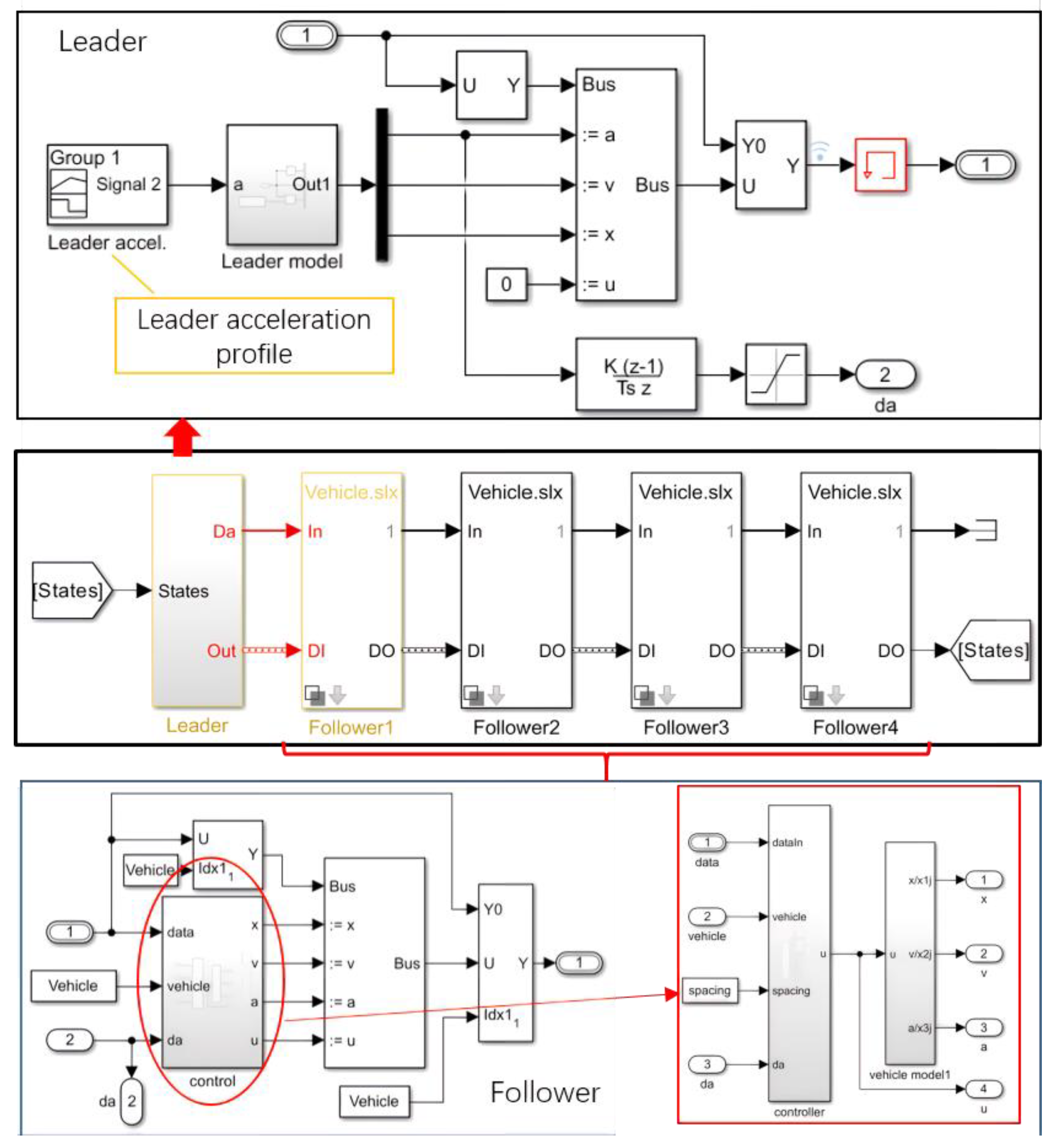
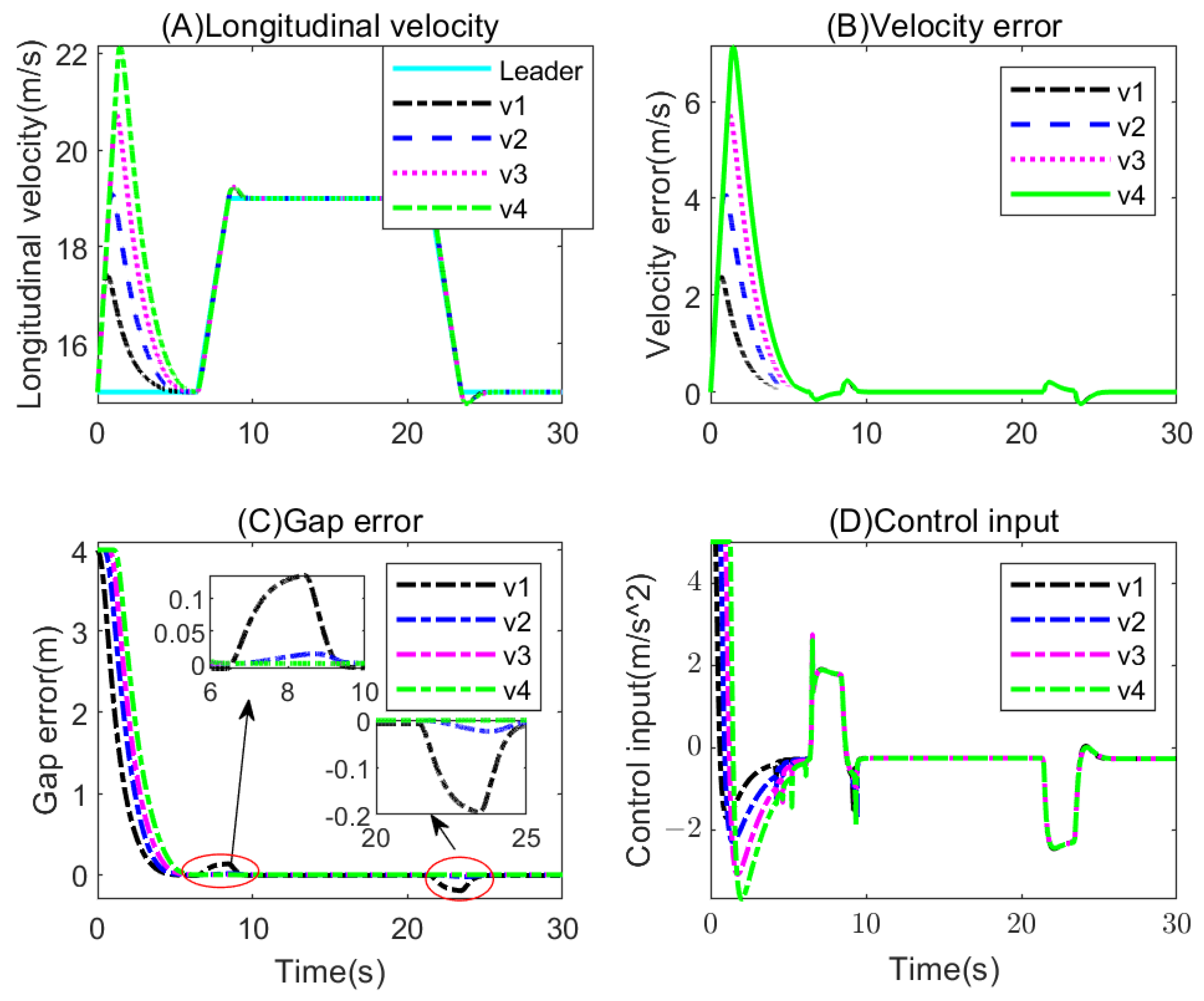
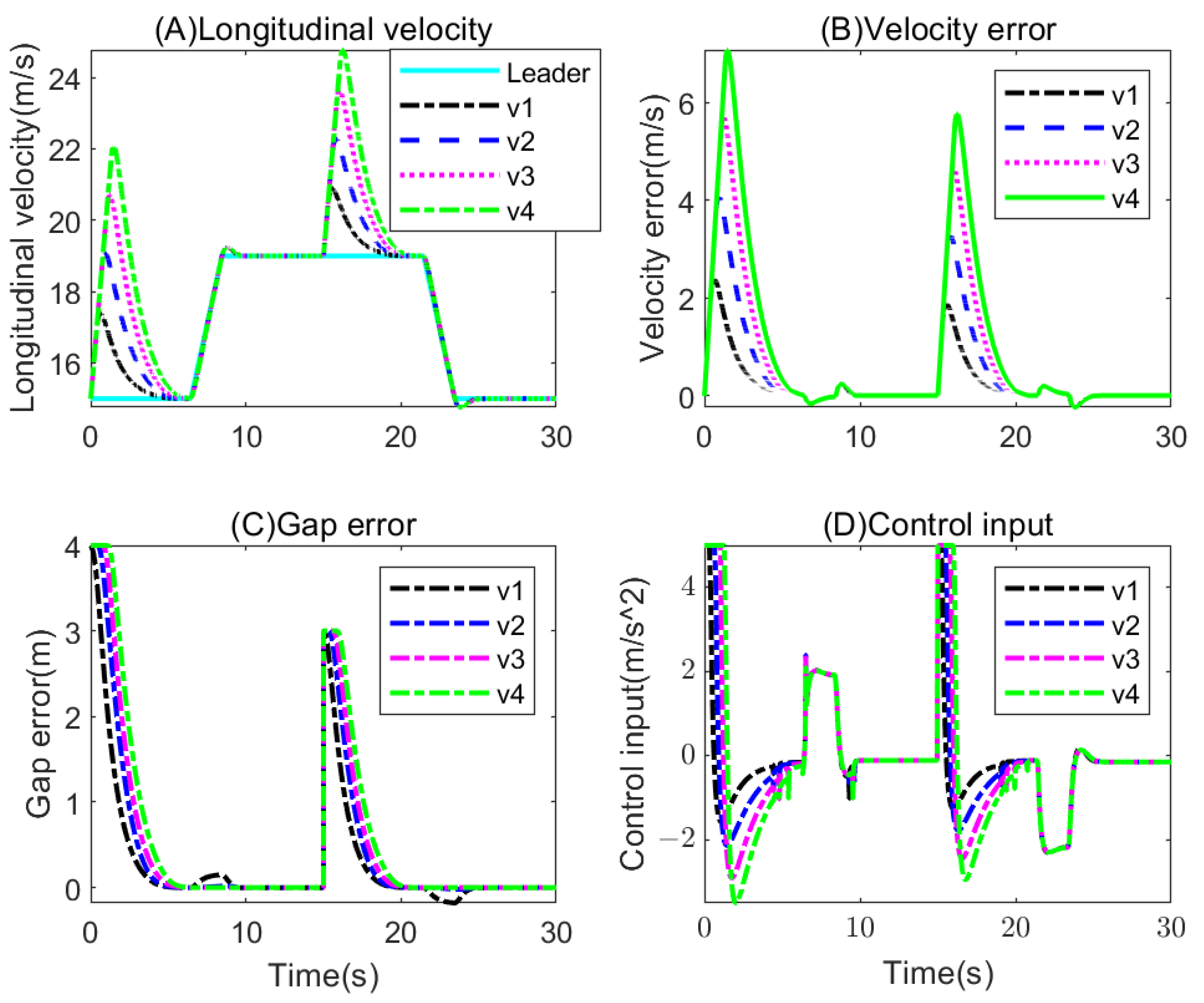
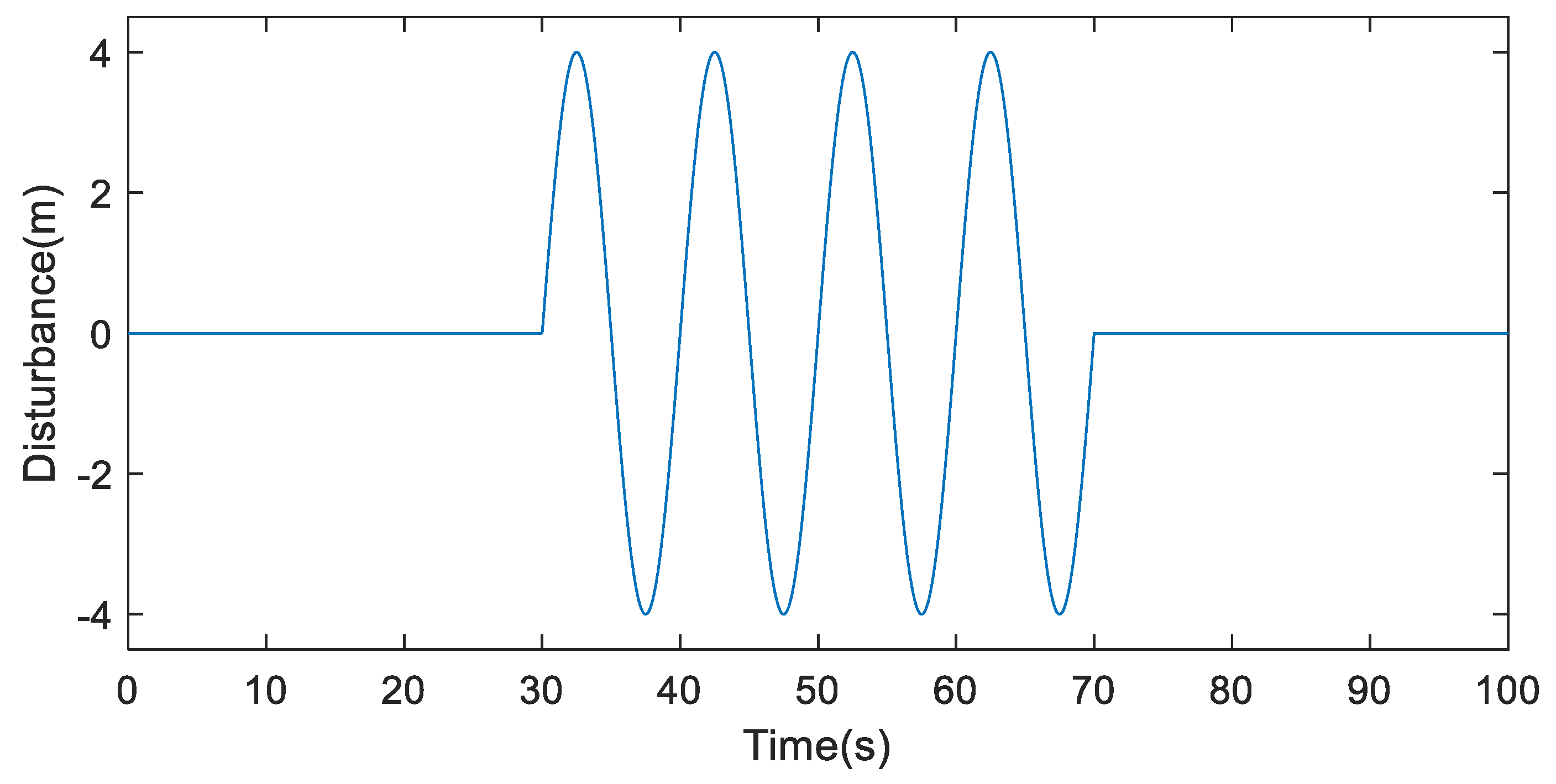
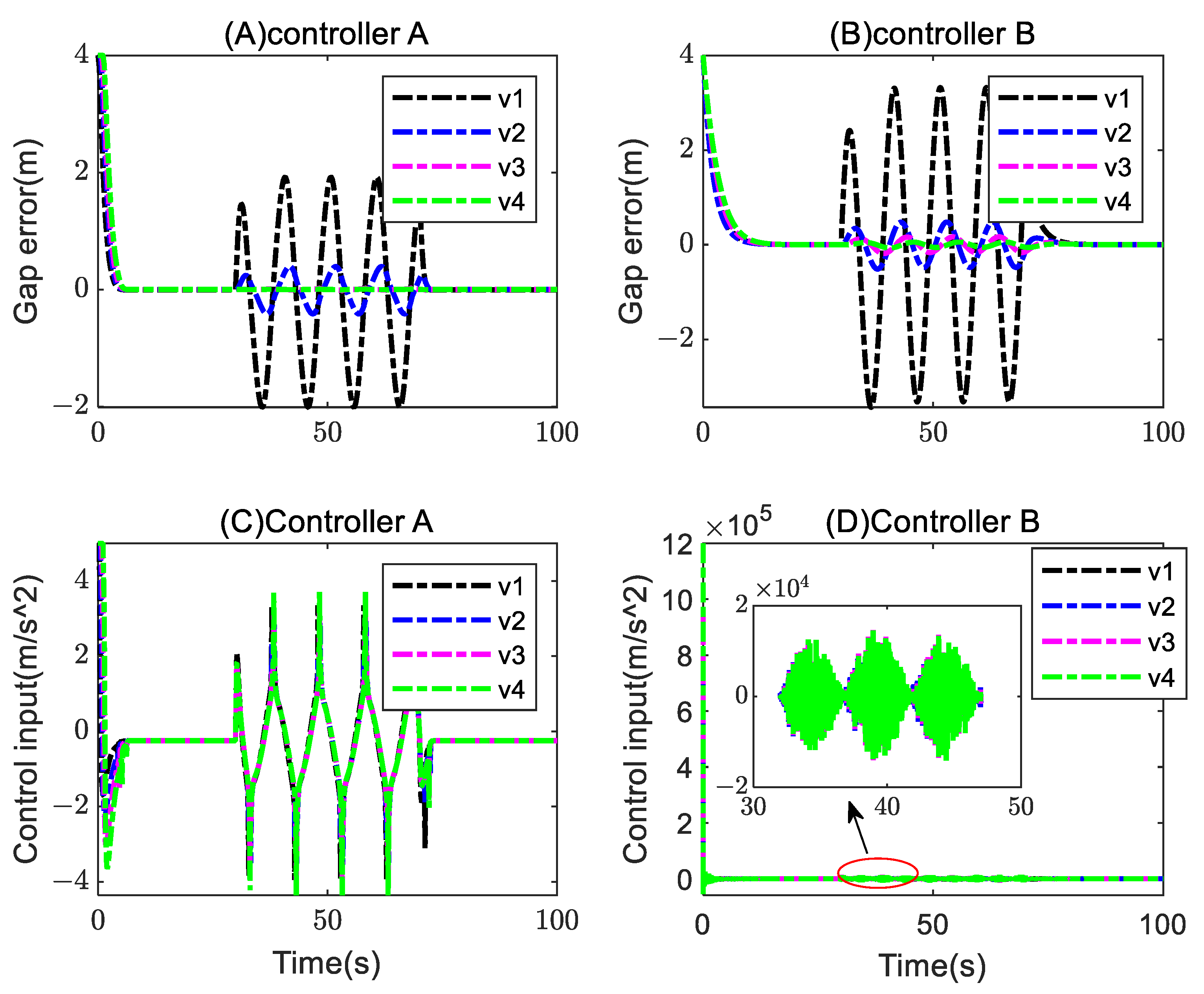
5. Simulation and Discussion

To test the performance of the proposed algorithm, three representative cases of simulations are conducted in MATLAB/Simulink, as shown in Figure 3. In the simulation, a five-vehicle platoon with one leader and four followers in a straight line is chosen as the tested truck platoon. In practice, the platoon is subject to unpredictable disturbance, so the calculated control input can be outside the reasonable range. Then, an amplitude limiting block is added to limit the control input range. The main parameters selected for the simulations are listed in Table 1.
Case (A). This case is simulated to verify the inner stability of the controller without uncertainties and disturbance. The initial positions are chosen as [ 40 , 30 , 20 , 10 , 0 ] T m with the leader as the first vehicle in the driving direction. The desired gap between following vehicles with the immediate predecessor is set as 6 m. To mimic the practical scenario in real-life driving, accelerating and decelerating processes shall be included in the speed profile for the leader. Then, the acceleration of the leader versus time can be designed, as shown in Figure 4. The position error is calculated as e p i = p i p i 1 h ,       i = 1 , 2 , , n , where p 0 represents the longitudinal position of the leader. The simulation results of Case (A) are shown in Figure 5.
As shown in the figure, the following vehicles accelerate with the maximum allowable acceleration due to initial position error in the starting process of the simulation, and reach the consensus state at about 6 s. As can be seen from Figure 5C, the first following vehicle exhibits the largest gap error in the acceleration and deceleration process, where the state change of the leader can be considered as disturbance for the following vehicles. As the gap error decreases downward of the platoon, nominal string stability can be achieved.
Case (B). This case is used to further test the stability and robustness of the controller against uncertainties and disturbances. Thus, based on the settings of Case (A), we apply such disturbance as wind and uncertainty as sudden change of desired gap. In this case, the face-up wind speed against the driving direction of the vehicles is set to a sinusoidal wave form with the amplitude of 10 m/s and the frequency of 0.1 Hz, and the desired gap error is changed to 3 m at 15 s. The simulation results are illustrated in Figure 6.
As shown in Figure 6A,B, the truck platoon can reach the consensus state in terms of velocity in spite of the uncertainty and disturbance. Although the control input of Case (B) is slightly larger than that of Case (A) because of the wind, the platoon can exert sufficiently large control input to diminish the corresponding gap error due to the effect of the wind and the sudden change of desired gap, and eventually reach the consensus state in terms of position, as can be seen in Figure 5C,D.
One point worth mentioning is that the designed controller can withstand other vehicle parameter variations such as the curb weight change, and the simulation results are quite similar to those illustrated in Cases (A) and (B).
Case (C). To illustrate the effectiveness and superiority of the designed controller, a sinusoidal form of disturbance is added directly to the position of the leader, as shown in Figure 7, while the velocity of the leader remains invariant. To make the robustness and stability performance more explicit, a classical consensus algorithm for platoon control is also applied as a comparison [30,31]; the algorithm is originated from multiagent system control, expressed as
u i = b [ v i ( t ) v r ] + 1 d i j = 0 N k i j a i j ( τ i v r ) 1 d i j = 0 N k i j a i j ( p i p j ( t τ i ) h i j v r ) ,
where b > 0 , k i j > 0 are both tunable parameters, τ i is aggregate transmission delay, and h i j is the time headway.
The simulation results of Case (C) are illustrated in Figure 8; the controller proposed in this paper is marked as “Controller A”, and the controller expressed in (29) is marked as “Controller B”. As can be seen in the figure, both controllers show robustness to the external disturbance, and the string stability is guaranteed as the gap error is attenuated downstream from the platoon. However, the controller designed in this paper is superior to controller B in terms of gap error, and the control input, unreasonable values, and high-frequency chattering can be observed in the control input of controller B, whereas controller A can maintain smaller gap error with control input in a reasonable range.

6. Conclusions

In this paper, a state-feedback and nonsmooth controller for a truck platoon is proposed, and the controller is robust to dynamic uncertainties and external disturbances. The simulation results validate the effectiveness and robustness of the controller. String stability is demonstrated both theoretically and experimentally. Moreover, the nonlinearities and disturbances shown in the dynamics model are not explicitly included in the control algorithm. Thus, the control algorithm can be easily applied to truck platoons with varied parameters and external disturbances, which can save the engineers a lot of time and energy in tuning parameters.
In the development of the control algorithm, the effect of delays such as the communication delay and input delay is not taken into consideration. Moreover, field test with real trucks is preferable and persuasive for the performance verification. The design of a nonlinear control algorithm considering delays and conducting field tests will be the topic of future research.

Author Contributions

Conceptualization and methodology, J.F.; software, Z.G.; validation, J.F. and B.G.; formal analysis, J.F.; investigation, Z.G.; resources, J.F.; data curation, J.F.; writing—original draft preparation, J.F.; visualization, J.F.; supervision, J.F.; project administration, B.G.; funding acquisition, J.F. All authors have read and agreed to the published version of the manuscript.

Funding

This research was funded by Guangxi Science and Technology Major Program, grant number AA23062031, and National Natural Science Foundation of China, grant number 52302508, 52302488.

Data Availability Statement

The data presented in this study are available on request from the corresponding author due to privacy.

Conflicts of Interest

Zepeng Gao is an employee of China North Vehicle Research Institute. Bingying Guo is an employee of China Merchants Testing Vehicle Technology Research Institute Co., Ltd. The paper reflects the views of the scientists and not the company.

References

  1. Ren, H.; Chen, S.; Yang, L.; Zhao, Y. Optimal Path Planning and Speed Control Integration Strategy for UGVs in Static and Dynamic Environments. IEEE Trans. Veh. Technol. 2020, 69, 10619–10629. [Google Scholar] [CrossRef]
  2. Chen, Y.; Chen, S.; Ren, H.; Gao, Z.; Liu, Z. Path Tracking and Handling Stability Control Strategy with Collision Avoidance for the Autonomous Vehicle Under Extreme Conditions. IEEE Trans. Veh. Technol. 2020, 69, 14602–14617. [Google Scholar] [CrossRef]
  3. Liu, Y.; Yao, D.; Wang, L.; Lu, S. Distributed Adaptive Fixed-Time Robust Platoon Control for Fully Heterogeneous Vehicles. IEEE Trans. Syst. Man Cybern. Syst. 2023, 53, 264–274. [Google Scholar] [CrossRef]
  4. Mosharafian, S.; Mohammadpour Velni, J. A hybrid stochastic model predictive design approach for cooperative adaptive cruise control in connected vehicle applications. Control Eng. Pract. 2023, 130, 105383. [Google Scholar] [CrossRef]
  5. Wang, J.; Li, X.; Park, J.H.; Guo, G. Distributed MPC-Based String Stable Platoon Control of Networked Vehicle Systems. IEEE Trans. Intell. Transp. 2023, 24, 3078–3090. [Google Scholar] [CrossRef]
  6. Wiseman, Y. Autonomous vehicles. In Research Anthology on Cross-Disciplinary Designs and Applications of Automation; IGI Global: Hershey, PA, USA, 2022; pp. 878–889. [Google Scholar]
  7. Bian, Y.; Du, C.; Hu, M.; Li, S.E.; Liu, H.; Li, C. Fuel economy optimization for platooning vehicle swarms via distributed economic model predictive control. IEEE Trans. Autom. Sci. Eng. 2021, 19, 2711–2723. [Google Scholar] [CrossRef]
  8. Wang, C.; Wang, D.; Peng, Z. Distributed Output-Feedback Control of Unmanned Container Transporter Platooning With Uncertainties and Disturbances Using Event-Triggered Mechanism. IEEE Trans. Veh. Technol. 2022, 71, 162–170. [Google Scholar] [CrossRef]
  9. Xiao, S.; Ge, X.; Han, Q.L.; Zhang, Y. Dynamic Event-Triggered Platooning Control of Automated Vehicles Under Random Communication Topologies and Various Spacing Policies. IEEE Trans. Cybern. 2022, 52, 11477–11490. [Google Scholar] [CrossRef]
  10. Ard, T.; Guo, L.; Han, J.; Jia, Y.; Vahidi, A.; Karbowski, D. Energy-efficient driving in connected corridors via minimum principle control: Vehicle-in-the-loop experimental verification in mixed fleets. IEEE Trans. Intell. Veh. 2023, 8, 1279–1291. [Google Scholar] [CrossRef]
  11. Yang, S.; Shladover, S.E.; Lu, X.-Y.; Ramezani, H.; Kailas, A.; Altan, O.D. A Bayesian regression analysis of truck drivers’ use of cooperative adaptive cruise control (CACC) for platooning on California highways. J. Intell. Transp. Syst. 2023, 27, 80–91. [Google Scholar] [CrossRef]
  12. Pirani, M.; Baldi, S.; Johansson, K.H. Impact of Network Topology on the Resilience of Vehicle Platoons. IEEE Trans. Intell. Transp. 2022, 23, 15166–15177. [Google Scholar] [CrossRef]
  13. Dolk, V.S.; Ploeg, J.; Heemels, W.P.M.H. Event-Triggered Control for String-Stable Vehicle Platooning. IEEE Trans. Intell. Transp. 2017, 18, 3486–3500. [Google Scholar] [CrossRef]
  14. Li, Y.; Tang, C.; Li, K.; He, X.; Peeta, S.; Wang, Y. Consensus-Based Cooperative Control for Multi-Platoon Under the Connected Vehicles Environment. IEEE Trans. Intell. Transp. 2019, 20, 2220–2229. [Google Scholar] [CrossRef]
  15. Dunbar, W.B.; Caveney, D.S. Distributed Receding Horizon Control of Vehicle Platoons: Stability and String Stability. IEEE Trans. Autom. Control 2012, 57, 620–633. [Google Scholar] [CrossRef]
  16. Zhang, L.; Sun, J.; Orosz, G. Hierarchical Design of Connected Cruise Control in the Presence of Information Delays and Uncertain Vehicle Dynamics. IEEE Trans. Control Syst. Technol. 2018, 26, 139–150. [Google Scholar] [CrossRef]
  17. Guo, H.; Liu, J.; Dai, Q.; Chen, H.; Zhao, W. A Distributed Adaptive Triple-Step Nonlinear Control for a Connected Automated Vehicle Platoon With Dynamic Uncertainty. IEEE Internet Things 2020, 7, 3861–3871. [Google Scholar] [CrossRef]
  18. Feng, S.; Sun, H.; Zhang, Y.; Zheng, J.; Liu, H.X.; Li, L. Tube-Based Discrete Controller Design for Vehicle Platoons Subject to Disturbances and Saturation Constraints. IEEE Trans. Control Syst. Technol. 2019, 28, 1066–1073. [Google Scholar] [CrossRef]
  19. Guo, X.; Wang, J.; Fa Ng, L.; Teo, R. Distributed Adaptive Integrated-Sliding-Mode Controller Synthesis for String Stability of Vehicle Platoons. IEEE Trans. Intell. Transp. 2016, 17, 2419–2429. [Google Scholar] [CrossRef]
  20. Li, S.E.; Yang, Z.; Li, K.; Wang, J. An Overview of Vehicular Platoon Control under the Four-Component Framework. In Proceedings of the Intelligent Vehicles Symposium 2015, Seoul, Republic of Korea, 28 June–1 July 2015. [Google Scholar]
  21. Kaviarasan, B.; Sakthivel, R.; Wang, C.; Alzahrani, F. Resilient control design for consensus of nonlinear multi-agent systems with switching topology and randomly varying communication delays. Neurocomputing 2018, 311, 155–163. [Google Scholar] [CrossRef]
  22. Khoo, S.; Xie, L.; Man, Z. Robust Finite-Time Consensus Tracking Algorithm for Multirobot Systems. IEEE/ASME Trans. Mechatron. 2009, 14, 219–228. [Google Scholar] [CrossRef]
  23. Swaroop, D.; Hedrick, J.K. String stability of interconnected systems. IEEE Trans. Autom. Control 1996, 41, 349–357. [Google Scholar] [CrossRef]
  24. Rajamani, R. Vehicle Dynamics and Control; Mechanical Engineering Series; Springer: New York, NY, USA, 2012. [Google Scholar]
  25. Hua, C.; Xiu, Y.; Guan, X. Adaptive Leader-Following Consensus for Second-Order Time-Varying Nonlinear Multiagent Systems. IEEE Trans. Cybern. 2017, 47, 1532–1539. [Google Scholar] [CrossRef]
  26. Xuan-Mung, N.; Golestani, M.; Hong, S.K. Constrained nonsingular terminal sliding mode attitude control for spacecraft: A funnel control approach. Mathematics 2023, 11, 247. [Google Scholar] [CrossRef]
  27. Zhao, Y.; Liu, Y.; Wen, G.; Ren, W.; Chen, G. Designing distributed specified-time consensus protocols for linear multiagent systems over directed graphs. IEEE Trans. Autom. Control 2018, 64, 2945–2952. [Google Scholar] [CrossRef]
  28. Ren, W.; Beard, R.W. Consensus algorithms for double-integrator dynamics. In Distributed Consensus in Multi-Vehicle Cooperative Control: Theory and Applications; Springer: London, UK, 2008; pp. 77–104. [Google Scholar]
  29. Li, X.; Tang, Y.; Karimi, H.R. Consensus of multi-agent systems via fully distributed event-triggered control. Automatica 2020, 116, 108898. [Google Scholar] [CrossRef]
  30. Di Bernardo, M.; Salvi, A.; Santini, S. Distributed consensus strategy for platooning of vehicles in the presence of time-varying heterogeneous communication delays. IEEE Trans. Intell. Transp. 2014, 16, 102–112. [Google Scholar] [CrossRef]
  31. Ren, W.; Atkins, E. Distributed multi-vehicle coordinated control via local information exchange. Int. J. Robust Nonlinear Control IFAC-Affil. J. 2007, 17, 1002–1033. [Google Scholar] [CrossRef]
Figure 1. Layout of the bidirectional-leader network topology for a truck platoon.
Wevj 15 00251 g001
Figure 2. Illustration of the overall controller design.
Wevj 15 00251 g002
Figure 3. Simulink model built for the simulations.
Wevj 15 00251 g003
Figure 4. The acceleration of the leader.
Wevj 15 00251 g004
Figure 5. Simulation results for Case (A).
Wevj 15 00251 g005
Figure 6. Simulation results for Case (B).
Wevj 15 00251 g006
Figure 7. Sinusoidal disturbance on leader position.
Wevj 15 00251 g007
Figure 8. Simulation results of Case (C).
Wevj 15 00251 g008
Table 1. Parameters selected for the simulations.
ParametersValueParametersValue
κ 10 α 1.5
λ 0.2 β 1
Disclaimer/Publisher’s Note: The statements, opinions and data contained in all publications are solely those of the individual author(s) and contributor(s) and not of MDPI and/or the editor(s). MDPI and/or the editor(s) disclaim responsibility for any injury to people or property resulting from any ideas, methods, instructions or products referred to in the content.

