Article

Intelligent Vehicle Formation System Based on Information Interaction

School of Technology, Beijing Forestry University, Beijing 100083, China
*
Author to whom correspondence should be addressed.
These authors contributed equally to this work.
World Electr. Veh. J. 2024, 15(6), 252; https://doi.org/10.3390/wevj15060252
Submission received: 10 May 2024 / Revised: 6 June 2024 / Accepted: 7 June 2024 / Published: 11 June 2024

Abstract

:
Urban traffic congestion has become an increasingly serious problem, and the transportation industry is gradually becoming a high-energy-consuming industry. Intelligent Transportation System (ITSs) that integrate technologies such as electronic sensing, data transmission, and intelligent control have emerged as a new approach to fundamentally solving transportation problems. As one of the cores of intelligent transportation systems, multi-vehicle formation technology has the advantage of promoting vehicle information interaction, improving vehicle mobility, and enhancing traffic conditions. Due to the high cost and risk of conducting multi-vehicle formation experiments using real vehicles, experimenting with intelligent vehicles has become a viable option. Based on the leader–follower formation strategy, this study designed an intelligent vehicle formation system using the Arduino platform. It utilizes infrared sensors, ultrasonic sensors, and photoelectric encoders to perceive information about the vehicle fleet and the road. Information is aggregated to the master vehicle through ZigBee communication modules. The controller of the master vehicle applies a PID algorithm, combined with a differential steering model, to solve the speed instructions for each vehicle in the fleet. Motion control instructions are then transmitted to each slave vehicle through ZigBee communication modules, enabling the automatic adjustment of the fleet’s traveling speed and spacing. Additionally, a Bluetooth app has been designed for users to monitor and control the movement status of the fleet dynamically in real time. Experimental verification has shown that this research effectively improves intelligent fleets’ capabilities in environmental perception, intelligent decision-making, collaborative control, and motion execution. It also enhances road traffic efficiency and safety, providing new ideas and methods for the development of autonomous driving technology.

1. Introduction

Urban traffic congestion is becoming an unmanageable problem. Its consequences span from economics, public health, and energy consumption to pollution, among others. In the United States, for example, automobile traffic has tripled across the country in the past 30 years. In many cities, the average speed during rush hour is only 13 km per hour, and the resulting economic losses are estimated to be as high as 120 billion USD per year. According to the projections of the Organization of Petroleum Exporting Countries, the transportation sector will account for 66.7% of the global total energy consumption from 2016 to 2040, making it a high-energy-consuming sector [1].
Since the increasingly serious road traffic problems cannot be fundamentally solved by simply increasing the traffic area of the traffic roads or from the vehicle perspective only, the use of advanced science and technology applied to traffic management has become a new idea to solve the above road traffic problems. Intelligent Transportation System (ITSs), which was created in the 1990s, is an efficient and accurate integrated traffic management system [2]. It reduces traffic congestion and improves road capacity by using advanced technologies, including electronic sensing technology, data transmission technology, and intelligent control, to provide drivers with road information and convenient services [3].
Multi-vehicle formation control technology is one of the core technologies of the intelligent transportation system. It can make the information interaction between vehicles timelier and more accurate, significantly reducing traffic congestion and improving road efficiency. In addition, multi-vehicle formation control technology can also reduce air resistance, which, in turn, reduces vehicle fuel consumption and emissions.
The implementation of multi-vehicle formation control technology relies on the infrastructure support of intelligent network technology. Intelligent network technologies provide the necessary complex environment sensing, intelligent decision-making, and cooperative control by realizing information interaction and data sharing among people, vehicles, roads, and the back end [4,5,6]. In particular, the convergence of vehicle automation and wireless communication is not only expected to achieve fundamental changes in transportation systems and enhance traffic safety and mobility but also help minimize the negative impact on the environment [7,8]. In recent years, advances in dedicated short-range communication (DSRC) technology have enabled vehicle-to-vehicle (V2V) and vehicle-to-infrastructure (V2I) communications [9]. In addition, the development of 5G technology further facilitates the ability of vehicles to sense and respond to their surroundings instantly, and the low-latency, high-bandwidth, and extremely high-reliability characteristics of 5G ensure agile responses and operational safety when dealing with complex road conditions [10].
The multi-vehicle formation control technique employs the pilot–follow method to achieve a coordinated movement among vehicles. In this control system, a pilot vehicle is responsible for the main information processing and decision-making. The other vehicles act as followers, executing movements according to the commands issued by the pilot vehicle [11,12,13]. The pilot vehicle is usually located at the front of the formation or at the most active position in the information interaction. This method is widely adopted for its simple design and ease of implementation. Aiming at the problem of formation control under the conditions of uncertainty of internal parameters and interference of an external environment, Han Lu designed an adaptive formation controller based on a linear feedback algorithm by establishing the attitude error model of pilot–following, which is able to realize the stable formation control of vehicles [14]. Li Runmei’s team from Beijing Jiaotong University improved the pilot–follower method and proposed the control problem of unmanned vehicles following time-varying relative distances and relative angles [15]. By setting up a specific error model between the pilot and the follower, the relative distance and relative angle are transformed into time-varying variables. Barbalat’s Lemma is novelly applied to demonstrate the asymptotic convergence of the tracking error from different perspectives [16].
Multi-vehicle formation technology inevitably faces the challenge of communication delays in complex communication environments. Literature [17] addresses this problem by proposing an in-platoon information management strategy. The strategy is to enclose communication, computation, and driving delays within an upper-bound delay and manage them at a higher level in a way that has no significant impact on platoon string stability. Literature [18] proposes an acceleration sliding mode controller based on the sliding mode control principle to cope with the interference caused by the delay by designing an improved safe inter-vehicle spacing strategy. Literature [19] considers the communication delay in the queue–following control and designs a distributed MPC (Model Predictive Control) method, which offsets the delay by moving the multi-bit elements of the corresponding delay intervals in the front-vehicle state information trajectory by shifting the multi-bit elements of the corresponding delay interval in the state information trajectory of the front vehicle to offset the interference of delay.
The deep integration of multi-vehicle formation control technology with other systems provides a new path for effectively solving urban traffic congestion problems. The traffic signal control system is an indispensable part of the intelligent transportation system, which complements the multi-vehicle formation control technology, and the two work together to reduce unnecessary stops and delays through real-time coordination and optimization of vehicle formations and traffic signals to improve the smoothness and efficiency of the overall traffic flow. At the same time, by introducing cutting-edge technologies such as Computational Intelligence (CI), the challenges of nonlinearity and stochasticity in the transportation system can be effectively addressed, injecting flexibility, autonomy, and robustness into urban traffic management [20]. In addition, A S. Akopov et al. have provided new perspectives and methods for solving optimization problems in complex transportation systems by developing new FTS models and FCGA algorithms, which not only demonstrate the great potential in improving the efficiency and safety of transportation systems but also open new paths for the development and application of ITS [21].
In the actual vehicle formation control experiments, we face the challenges of maintenance complexity, high cost, and safety hazards. In order to effectively deal with these challenges, we chose self-developed intelligent vehicles as the experimental objects and successfully built a multi-intelligent vehicle formation control research platform using ZigBee wireless communication technology.
The purpose of this study is to realize the stable formation control of multiple intelligent vehicles in the experimental environment by designing the system’s cooperation structure, communication method, hardware circuit, and software formation algorithm. This study will not only help verify the feasibility of our technical solution but also provide strong theoretical and practical support for intelligent networked vehicle formation control technology [22]. Meanwhile, this study also lays a solid foundation for the realization of multi-vehicle cooperative driving in future intelligent transportation systems [23] and provides new ideas and methods for the development of automatic driving technology.

2. System Design

2.1. Structure of Intelligent Vehicle Information Interaction System

The overall system structure is shown in Figure 1. The formation of intelligent vehicles in this design consists of three intelligent vehicles, one of which is the master vehicle, and the other two are the slave vehicles. The three intelligent vehicles mainly include a motor drive module, photoelectric measurement speed module, ultrasonic distance measurement module, obstacle avoidance module, and ZigBee communication module. Additionally, the master vehicle is equipped with an infrared sensor module and Bluetooth module. In practical situations, the master vehicle accurately captures road data through the infrared sensor module and measures its actual speed through a photoelectric encoder. These data are then transmitted in the form of digital signals to the Arduino microcontroller it carries [24,25]. The built-in program in the master vehicle’s microcontroller effectively processes these signals to control the master vehicle. Furthermore, a speed PID controller in the master vehicle implements a closed-loop feedback mechanism for precise speed regulation, achieving high-precision steady-state control of the vehicle speed, thus realizing autonomous routing movement. The slave vehicles measure their actual distances from the preceding vehicle using ultrasonic sensors and their respective speeds through photoelectric encoders. This information is then transmitted to the master vehicle’s microcontroller via the ZigBee communication module. The integrated fleet spacing PID controller in the master vehicle’s microcontroller accurately calculates the slave vehicle speed control instructions required to maintain a preset platoon spacing through a closed-loop feedback mechanism. Movement information is transmitted to the processors of the slave vehicles through the communication module, providing navigation for their routing. This design achieves cooperative control of the vehicle movement. In particular, a remote human–machine monitoring system in the Android environment, designed by the authors [26,27], satisfies the need for manual remote control and fleet monitoring.
The design of the intelligent vehicle formation information interaction system adopts a hybrid control strategy, which is a collection of centralized and distributed architectures. In the hybrid architecture, the main control unit holds all the information of the system, and it can well coordinate the various intelligent vehicles in the system, deriving the optimal planning for the stable movement of the fleet and sending commands to the other intelligent vehicles through the wireless communication network. At the same time, the slave vehicles could also exchange information with each other and provide feedback on their own speed information to the main control unit, which further enhanced the overall coordination of the system.

2.2. System Hardware Design

The hardware of the intelligent vehicle adopts the modularized design concept. The overall design of the hardware of the intelligent vehicle is shown in Figure 2, which mainly includes the following modules.

2.2.1. Processor Module

A processor module, as the brain of the intelligent vehicle, is used to receive information and send control commands. The module adopts Arduino UNO R3, which is an 8-bit microcontroller development board based on Atmega328, with a maximum operating frequency of 20 MHz and a processing performance of up to 20 MIPS.
Arduino UNO R3 is an 8-bit microcontroller development board based on Atmega328, equipped with a wealth of input and output ports. It features 14 digital IO ports (numbered 0 to 13, with 6 supporting PWM signal output) and 6 analog ports (A0 to A5) that can be used for digital or analog signal inputs and outputs. These versatile IO ports enable an easy connection to various peripherals. Figure 3 shows the principle of the master vehicle microcontroller connected to peripherals.
Arduino IDE, as the official development environment for Arduino hardware, features an integrated serial monitor that can display the data transmission of Arduino devices in real time, including data sent and received. This function provides crucial support for developers in debugging and validating communication functions.

2.2.2. Four-Channel Infrared Sensor Module

The Infrared (IR) sensors consist of infrared LED and infrared photodiodes. The IR LED is called the light emitter, and the IR photodiode is called the receiver. The infrared LED emits light that illuminates the target surface, and the surface reflects part of the light. The photodiode detects the intensity of the reflected light and converts it into a digital signal through a voltage divider circuit and an operational amplifier comparator circuit. This digital signal is then fed into a microcontroller via the digital port on the mainboard for processing. Through the A/D interface, the intelligent vehicle processor reads the infrared sensor output at high and low levels and then determines the guideline’s position to achieve the intelligent vehicle line cruise. The four infrared sensors are named LS [1], LS [2], RS [1], and RS [2], from left to right.
The Arduino UNO development board’s digital ports A5, A4, A0, and A1 serve as inputs to the four-channel infrared sensor. Suppose any sensor among LS [1], LS [2], RS [1], or RS [2] detects a High-Reflectance Zone. In that case, it sends a low-level signal to the corresponding pin of the Arduino microcontroller in the master vehicle. Conversely, if a Low-Reflectance Zone is detected, it sends a high-level signal. These input signals can be used to control the motion of the intelligent vehicle. Detailed instructions can be found in Table 1.

2.2.3. Photoelectric Speed Measurement Module

The photoelectric encoder is used to capture the speed of the motion of the intelligent vehicle. It is realized using a motor-driven code disk, which alternately passes through the photoelectric transmitter with its transparent and opaque sections during rotation. The system utilizes a timer interrupt to record the number of these changes at a specified time and outputs the data to the processor through the IO port.
Equation (1) can express the rotational speed:
n = M 0 C T 0
where C is the total number of encoder pulses per revolution, M0 is the number of encoder pulses calculated within time T0.
Linear speed can be represented as Equation (2):
V = n · π · D
where D is the wheel diameter.

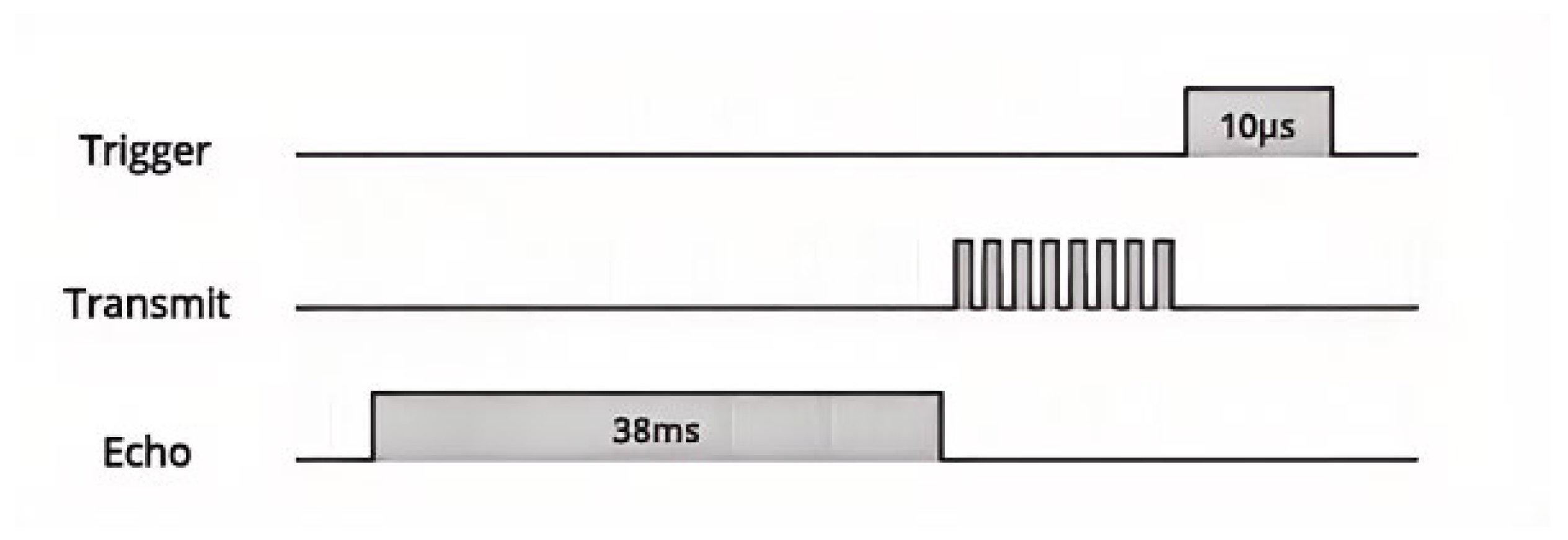
2.2.4. Ultrasonic Distance Measurement Module

The HC-SR04 ultrasonic distance measurement module can provide a 2 cm–400 cm non-contact distance sensing function; the distance measurement accuracy can be as high as 3 mm. The typical operating voltage is 5 V, the detection distance is 2 cm–400 cm, the detection angle is 15, and the module includes an ultrasonic transmitter, receiver, and control circuit.
Ultrasonic transducer working schematic is shown in Figure 4. Firstly, a pulse lasting at least ten µS is emitted to the trigger pin through the IO port. Subsequently, the module automatically generates eight 40 kHz square waves to detect whether a signal has been returned. This unique 8-pulse emission mode enables the receiver to distinguish the square wave from the ambient ultrasonic noise. The eight ultrasonic pulses propagate through the air, moving away from the emitter. Simultaneously, the echo pin turns high, marking the commencement of the echo signal. If these pulses are not reflected back, the echo signal will time out after 38 ms and return to a low level. Therefore, a 38 ms pulse indicates no obstruction within the sensor range.
If these pulses are reflected back, the echo pin will turn low upon receiving the signal. This generates a pulse whose width varies between 150 µS and 25 ms, depending on the time taken to receive the signal.
Then, the width of the received pulse can be used to calculate the distance to the reflecting object. By utilizing the pulse function in the Arduino IDE library, the duration of the pulse signal can be accurately measured. The distance to the target object can be precisely calculated using Equation (3):
S = V Δ t 2
where S is the emission point for the pulse time difference, V is the velocity of sound.

2.2.5. ZigBee Communication Module

In order to meet the demands of communication between vehicles, we designed a wireless communication system based on ZigBee technology, and the system uses four DL-20 wireless serial pass-through modules (using CC2530 chips) as vehicle–vehicle communication nodes. CC2530 utilizes a low-power SoC design with an integrated ZigBee communication stack and radio frequency part, which provides high performance and flexibility to build robust network nodes at a meager cost.
The ZigBee network is constructed based on the ZigBee protocol stack, as illustrated in Figure 5. Its core foundation is rooted in the IEEE 802.15.4 international standard at the bottom layer, while the ZigBee Alliance specifies the network layer. Additionally, the user customizes the upper layer protocol. ZigBee technology has become one of the most important technologies in the field of wireless network information transmissions with its short distance, low complexity, low power consumption, low data rate, low cost, and high capacity. Its complete protocol stack requires only 32 kB, which means the technology can be easily embedded in various devices.
This module has two communication modes: point-to-point and broadcast communication. In the point-to-point communication mode, the module is able to achieve a zero-packet-loss rate and very low latency (about 40 ms) to ensure that control commands are transmitted without loss, which is crucial for maintaining the driving stability of the formation of intelligent vehicles. The formation of intelligent vehicles is configured with two pairs of DL-20 modules (acting as end nodes) to establish point-to-point wireless network communication.
Through the utilization of the DL-20 2.4G ZigBee wireless serial transparent transmission module, user-oriented transparent transmission is achieved. During the process of transparent data transmission, users are not required to understand complex communication protocols or process the transmitted data. They simply need to transmit the content as binary data to the target node. This simplicity is due to the adoption of a concise data format during the information exchange between the transmitting module (with receiving functionality) and the receiving module (which also possesses transmitting capability). This format eliminates the need for conventional packet information, such as command headers and end markers. Throughout the entire communication process, data transfer between microcontrollers resembles a direct wired connection between their serial ports. The uploaded information remains identical to the received information, rendering the wireless transmission link completely transparent to the user. The principle of transparent transmission is illustrated in Figure 6.
The following introduces the communication process between a lead vehicle and a following vehicle as an illustrative example. In this system, the communication between the lead and following vehicles employs a full-duplex mode, which enables bidirectional information transmission. Operating under the point-to-point mode of DL-20, it is essential to ensure that both the lead and following vehicles’ DL-20 modules are adequately initialized and configured with matching channels and baud rates. Subsequently, the DL-20 module of the following vehicle encapsulates the velocity and distance information relative to the preceding vehicle into a data packet compliant with the ZigBee protocol. This packet is then transmitted wirelessly via the radio frequency (RF). During transmission, the data packet may encounter interference or attenuation; however, the ZigBee protocol guarantees reliable data delivery through error correction and retransmission mechanisms. Upon receiving the data packet, the DL-20 module of the lead vehicle verifies its integrity and destination address to confirm that it is both undamaged and intended specifically for it. After that, the lead vehicle unpacks the data, extracts the information uploaded by the following vehicle, takes external environmental factors into account, derives an optimal plan for the platoon, and finally sends motion control instructions back to the following vehicle using the same methodology.

2.2.6. Bluetooth Networking Module

The HC-05 Bluetooth module has two modes, master and slave, and can flexibly switch roles according to different commands. By default, as a slave, it can be paired with Bluetooth devices such as cell phones, which are widely used in navigation systems. The module adopts the serial communication mode, utilizing the TX/RX serial port to send and receive commands. By configuring the corresponding microcontroller serial port, it can realize the sending and receiving of data.
Serial communication with HC-05 on the main control unit is mainly through Bluetooth. The human–machine monitoring system is designed with a remote control interface for the intelligent vehicle, which allows the user to send control commands to the main control unit via cell phones or other mobile devices; it is also designed with a fleet operation mode selection function, which allows the user to select the fleet’s autonomous route-following mode or manual takeover mode according to the needs. The fleet status display interface gives users real-time status information on each intelligent vehicle.

2.2.7. Motor Drive Module

The processor will send two pulse width modulation (PWM) signals to the drive module to control the left and right DC motors. By precisely adjusting the duty cycle of these PWM signals, the running speed of each group of motors can be effectively regulated, thus realizing the vehicle’s acceleration, deceleration, and start/stop. In addition, the vehicle can realize steering control by applying different speeds to the left and right motors.
PWM is the pulse width modulation. It is a method of controlling the output power by adjusting the size of the width of the pulse within a modulation cycle. When the motor is always connected to the power supply, the maximum speed of the motor is Vmax, and the duty cycle is D = t/T. The average speed of the motor is
V d = V m a x · D
where Vd represents the average speed of the motor, Vmax represents the speed of the motor when fully energized (maximum), and D = t/T represents the duty cycle.
From the above equation, changing the duty cycle can achieve a different average speed of the motor to achieve the purpose of speed control. Next, we analyze the kinematics of the intelligent vehicle and parse the commands:
We refer to Ackerman’s principle of steering geometry, i.e., all four tires rotate approximately around a center when the vehicle is steering to ensure the stability of the vehicle. Ignoring the influence of road surface changes, the kinematic model of the four-wheel drive differential steering vehicle can be derived, as shown in Figure 7.
In Figure 7, α1 and α2 are the turning angles of the front left wheel and the rear left wheel, and the front right wheel and the rear right wheel, respectively; 2L is the distance between the left and right wheels; 2K is the distance between the front axle and rear axle; V is the linear velocity of the center of mass, and ω is the angular velocity of the vehicle, V1, V2, V3, and V4 are the velocities at the center of the wheels, whose directions are perpendicular to the radial direction of the rotation radius and can be decomposed into the longitudinal component velocity V j y (j = 1, 2, 3, 4) along the rolling direction of the wheels and the transverse component velocity V j x (j = 1, 2, 3, 4) along the axial direction of the motor.
V j y is the pre-determined target speed, i.e., the target speed of the vehicle in the wheel-rolling direction.
V j x denotes the transverse sliding velocity, i.e., the transverse displacement velocity of the body concerning the ground due to the different rotational speeds of the inner and outer wheels.
The relationship between each velocity and turn angle can be derived from
V 1 = ω R 1 = ω K sin α 1
V 2 = ω R 2 = ω K sin α 2
V 3 = V 1 = ω K sin α 1
V 4 = V 2 = ω K sin α 2
V 1 y = V 1 cos α 1 = ω K tan α 1 = ω ( R L )
V 2 y = V 2 cos α 2 = ω K tan α 2 = ω ( R + L )
V 3 y = V 3 cos α 1 = ω K tan α 1 = ω ( R L )
V 4 y = V 4 cos α 2 = ω K tan α 2 = ω ( R + L )
where
R = V / ω
Then, the rotational speed of the motor is
n j = V j y i 2 π r , j = 1 ,   2 ,   3 ,   4
where i is the reduction ratio of the reducer, r is the radius of the wheels.
Based on the above analysis, by bringing the structural parameters of the vehicle and the y-direction linear velocity V j y i (j = 1, 2, 3, 4) into Equation (13). We can obtain the rotational speed n of each motor under the corresponding motion command.
Table 2 lists the partial control commands in order to facilitate the precise control of the vehicle and the standardized implementation of the commands.

2.3. System Software Design

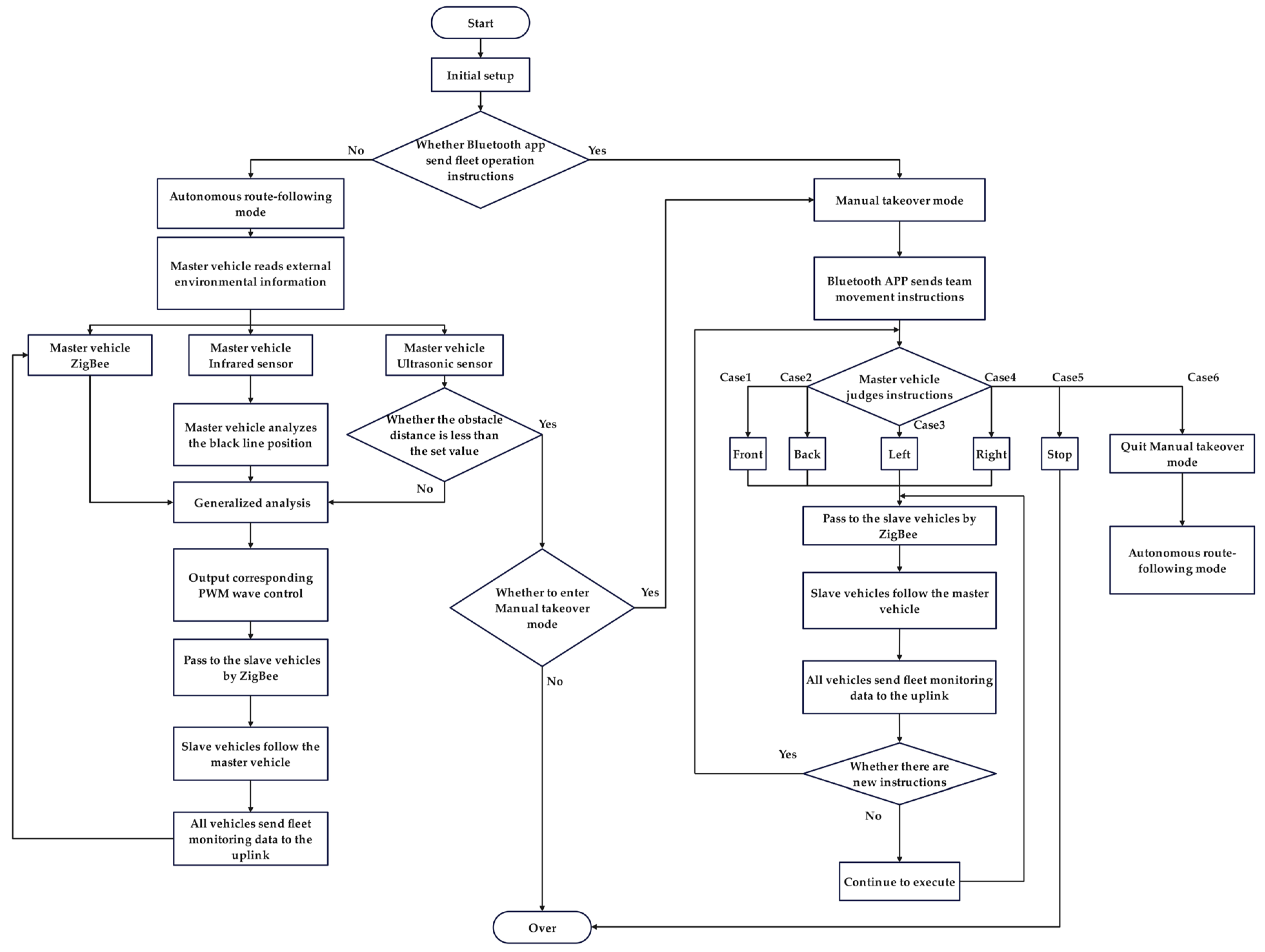
2.3.1. General Design of the System Program

The workflow of the intelligent vehicle formation system is shown in Figure 8. After the intelligent fleet is activated, the operation mode of the fleet is determined by the master vehicle’s Arduino microcontroller, which detects the data status in the Bluetooth serial buffer. Specifically, when the Bluetooth serial buffer is empty, the fleet will enter an automatic route-following mode. At this point, the photosensitive element of the master vehicle’s infrared sensor captures the light intensity of the road, converting it into electrical signals that are then transmitted to the microcontroller. The Arduino microcontroller receives the information from the infrared sensor, performs rapid analysis, and derives the desired speed based on Table 2. The photoelectric encoder on the master vehicle continuously measures the actual speed of the master vehicle and adjusts its speed through the master vehicle speed PID controller to match the desired speed from the motion control instructions. The slave vehicles transmit their speed and the distance data between themselves and the preceding vehicles to their own microcontrollers via photoelectric encoders and ultrasonic sensors. They then send this speed and distance data to the master vehicle’s microcontroller via ZigBee. Upon receiving this data, the master vehicle calculates the slave vehicles’ motion information based on the fleet spacing PID controller to ensure the entire fleet forms a stable formation. Once the calculations are complete, the master vehicle transmits the motion control data to the slave vehicles via ZigBee. The slave vehicles adjust their driving posture based on this information. We have installed an ultrasonic sensor at the center of the master vehicle’s front to continuously monitor the distance between it and any obstacles ahead. If the distance between the master vehicle and an obstacle is less than a preset safety value, the obstacle avoidance function will be triggered, causing the entire fleet to stop and wait for manual intervention.
When the user clicks the “Manual Takeover” button on the Bluetooth APP, the Bluetooth buffer is not empty, causing the fleet to exit the automatic route-following mode and switch to manual control. The user issues control commands via the Bluetooth app, directly instructing the master vehicle on the movement speed. The photoelectric encoder on the master vehicle will continue to detect the actual speed of the master vehicle and input the data to the master vehicle speed PID controller. The controller adjusts the speed of the master vehicle to match the desired speed. Meanwhile, the slave vehicles still transmit their respective speed and spacing parameters to the master vehicle. The fleet spacing PID controller on the master vehicle transmits the calculated motion instructions to the slave vehicles via ZigBee. The slave vehicles adjust their driving states based on this information. Then, the master vehicle transmits the fleet’s information to the Bluetooth app via its Bluetooth module, allowing the user to monitor it in real time.
The vehicles’ movements, turns, and starts/stops are controlled by the digitalWrite(pin, value) function, where the pin parameter specifies the pin to be operated, and the value parameter determines the output voltage (HIGH for high level, LOW for low level). Acceleration and deceleration of the vehicle are performed through the analogWrite(pin, value) function, requiring the pin parameter to be one of the supported pins, and the value parameter controls the duty cycle of PWM output, ranging from 0 to 255, equivalent to 0 to 100% duty cycle. The microcontroller measures the duration of the ultrasonic pulse using the pulseIn() function and calculates the speed of sound propagation to determine the measured distance.
The programming of the coordinator and terminal node procedures for the communication module fully utilizes the built-in library functions provided by the platform. We have employed the SoftwareSerial library, which enables us to simulate additional hardware serial ports. Taking the communication between the master vehicle and the first slave vehicle as an example, firstly, in the setup function, we initialized two serial ports: the slave vehicle connects to the master vehicle’s soft serial port through its own soft serial port (with pin two as RX and pin three as TX; the pin settings are the same for both the master and slave vehicles). Within the loop function, we continuously check if data are available on the computer’s serial port. If they are (ZigBeeSerial.available() > 0), we read and print the received characters using the Serial.read() and Serial.print() functions. When data need to be sent, the Serial.write() function is used to transmit the data to the device connected to the serial port.
When switching to manual control mode (BTSerial.available() > 0), the master vehicle executes the respective actions using the same functions based on the commands sent by the Bluetooth APP.

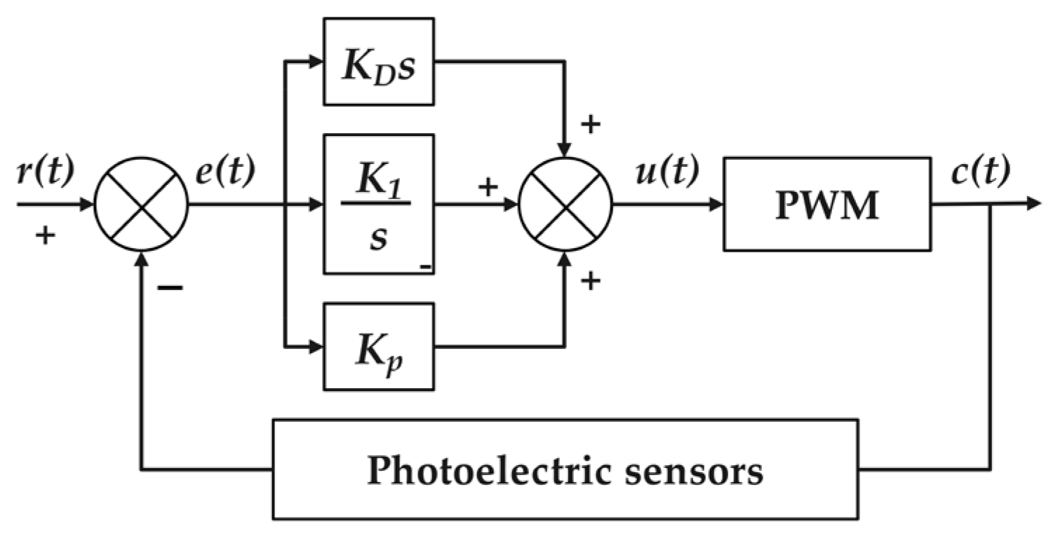
2.3.2. Generalized Analysis

  • Master vehicle speed PID controller design;
The principle of the PID algorithm is to measure the deviation between the controlled variable and the expected value and output the control volume according to certain control rules (common control rules are proportion P, integral I, and differential D), ultimately achieving the desired control effect. The control schematic diagram is shown in Figure 9.
In this context, r(t) represents the system input, which is the expected movement speed of the master vehicle. c(t) denotes the system output, i.e., the actual movement speed by the photoelectric sensors of the master vehicle measured. u(t) stands for the output control volume of the PID controller. e(t) represents the system deviation, which is the difference between the actual speed and the expected speed of the master vehicle, calculated as e(t) = r(t) − c(t). Equation (14) presented is the continuous PID control law.
u ( t ) = k p ( e ( t ) + 1 T i e ( t ) d t + T d d e ( t ) d t )
In Equation (14), k p is the proportional coefficient, Ti is the integral time constant, and T d is the derivative time constant. Among them, k p e ( t ) represents the proportional term, which is used to eliminate deviations. The controller calculates the control output based on the product of the current deviation value of the system and the proportionality coefficient kp, allowing the system to respond quickly to deviation signals. The response speed of the system is proportional to k p . However, if k p is too large, it can easily render the system unstable and prone to oscillation, while the use of proportional control alone inherently produces residual errors. 1 T i e t d t represents the integral component, which is used to eliminate the residual errors in the system. The controller calculates the control output based on the product of the definite integral of the deviation in the past sampling period Ts and the integral coefficient 1 T i , ensuring that the system can finally reach the desired response speed without errors, stabilizing at the target value without deviation. Nevertheless, when the integral is too strong (i.e., when (Ti) is very small), integral control may also prolong the response time of the system and potentially lead to integral saturation in the presence of large perturbations or persistent deviations of the system, resulting in degradation of the system performance. T d d e ( t ) d t represents the derivative component. (Td) acts on the rate of change of the system deviation. The controller calculates the control output based on the product of the differential value of the deviation and the differential coefficient Td. When the deviation changes rapidly, a correction signal is introduced in advance to compensate for the lag in system control, making the system more sensitive to external disturbances. It helps to reduce the amount of overshooting of the system and improves its dynamic performance and stability. However, when the differential coefficients are too large, the noise will overamplify and lead to system instability.
In practical digital control systems, since the system itself is discrete, the concept of continuous domain integration needs to be discretized for digital processing, i.e., accumulating errors for each sampling period as a way to approximate the effect of continuous integration.
The continuous PID algorithm is discretized to obtain a digital PID control algorithm as shown in Equation (15).
u ( n ) = K p e ( n ) + K i k = 0 n   e ( k ) + K d ( e ( n ) e ( n 1 ) )
where u(n) represents the output of the controller at the nth sampling moment. e(n) represents the difference between the actual and expected speeds of the master vehicle at the nth sampling moment.
In this case, the use of integration is conceptually consistent with discretized accumulation, both aiming to reflect the accumulation of errors.
K i k = 0 n   e ( k ) represents the integral of speed errors from the initial moment to the current moment, representing the accumulation of all speed deviations and embodying the integral term.
The aforementioned classic PID algorithm requires storing the deviation at every step, consuming a large amount of storage space and computational resources. For this system, which needs to run for a long time or has resource constraints, an incremental PID control algorithm can be used, which replaces the original cumulative effect of the integral link by deriving the increment, avoiding the integral link from taking up a lot of computational performance and storage space.
The incremental PID is shown in Equation (16)
u 1 = u 1 n u 1 n 1 = K 1 p ( e 1 ( n ) e 1 ( n 1 ) ) + K i e 1 ( n ) + K 1 d ( e 1 ( n ) 2 e 1 ( n 1 ) + e 1 ( n 2 ) )
Based on this, we can calculate
u 1 ( n ) = u 1 ( n 1 ) + K 1 p ( e 1 ( n ) e 1 ( n 1 ) ) + K 1 i e ( n ) + K 1 d ( e ( n ) 2 e 1 ( n 1 ) + e 1 ( n 2 ) )
By reasonably selecting the values of K1p, K1i, and K1d, the master vehicle’s speed can respond more quickly and accurately to changes in the expected speed while maintaining good stability.
2.
Fleet spacing PID controller design;
The control schematic diagram of the PID controller for platoon spacing is shown in Figure 10.
In this context, r(t) represents the system input, which is the expected spacing between the slave vehicle and the vehicle ahead. c(t) denotes the system output, specifically the actual spacing measured by ultrasonic sensors between the two vehicles after adjustment by the controller. u(t) stands for the output control variable. e(t) indicates the system deviation, defined as the difference between the desired spacing and the actual spacing between the vehicles, where e(t) = r(t) − c(t). The PID control method is similar to the master vehicle speed PID controller, following Equation (18).
u 2 ( n ) = u 2 ( n 1 ) + K 2 p ( e 2 ( n ) e 2 ( n 1 ) ) + K 2 i e ( n ) + K 2 d ( e ( n ) 2 e 2 ( n 1 ) + e 2 ( n 2 ) )
By reasonably selecting the values of K2p, K2i, and K2d, the fleet spacing can respond more quickly and accurately to changes in the expected spacing while maintaining good stability.
3.
Vehicle following strategy.
We install an ultrasonic distance measure module on the left front and right front of the slave vehicle’s head, respectively, and calculate the distance to objects independently.
As shown in Figure 11 and Figure 12, when the difference between the detected distances Sl and Sr exceeds a certain threshold, it is judged that there is a certain angle difference between the movement direction of the rear vehicle and the front vehicle. If Sl is greater than Sr, the vehicle turns right; if Sl is less than Sr, the vehicle turns left. This adjustment continues until the difference between Sl and Sr is less than the given threshold. When the detected difference between Sl and Sr is less than the given threshold, it is judged that the speed direction of the rear vehicle is the same as that of the front vehicle.
Calculate the average of Sl and Sr and use it as the distance S between the rear vehicle and the front vehicle. When the rear vehicle detects that the average distance S from the front vehicle is not equal to the pre-determined stable fleet spacing S0, the fleet spacing PID controller will be activated to adjust the speed of the front vehicle. The set value of the PID controller will be set as the stable fleet spacing S0, while the current value is the actually monitored average distance S. Through the calculation of the PID controller, a control output will be obtained. If the calculated control output is positive, it means that the rear vehicle needs to accelerate to reduce the spacing with the front vehicle; if the control output is negative, it means that the rear vehicle needs to decelerate to increase the spacing with the front vehicle. When the spacing between the two vehicles approaches the stable fleet spacing S0 after adjustment by the PID controller, the control output will gradually approach zero. At this time, the rear vehicle will drive at its original speed without further acceleration or deceleration adjustments, ultimately stabilizing the spacing between the rear vehicle and the front vehicle at S0.

2.3.3. Design of Bluetooth APP

App Inventor is a web application design tool developed by Google Labs that allows users to design and develop the interface of an Android application and its functionality directly in a web browser. Based on this platform, we developed a remote human monitoring system. Through the Android smartphone app, users can monitor the motion status of the smart vehicle in real-time and dynamically via Bluetooth wireless communication. The display interface for the app is depicted in Figure 13.
The system realizes the activation, exploration, and connection of the Bluetooth function and uses the Bluetooth serial communication protocol between the cell phone and the HC-05 module for data transmission. Users can remotely control the intelligent vehicles and select the fleet operation modes, such as autonomous route-following or manual takeover, via mobile devices. The system’s fleet status display interface provides real-time vehicle status information, which enhances the user’s operational convenience and system transparency. The commands and functions sent by the function buttons of the APP manual takeover interface are shown in Table 3.

3. System Test

3.1. Vehicle Formation Operation Test under a Straight Road

  • To further verify the stability of this vehicle formation and the accuracy of the Zigbee communication, we designed a single-lane road experimental scenario to experiment with the PID constant spacing formation control algorithm, as shown in Figure 14.
  • Three intelligent vehicles traveling in formation; the intelligent vehicles transmit state information (e.g., speed, fleet spacing, etc.) to the master vehicle through the ZigBee wireless communication network, and the master vehicle applies the PID constant spacing algorithm to control the formation, with the initial spacing and the safety spacing between the intelligent vehicles set to 20 cm, and the initial speed of the three vehicles set to zero.
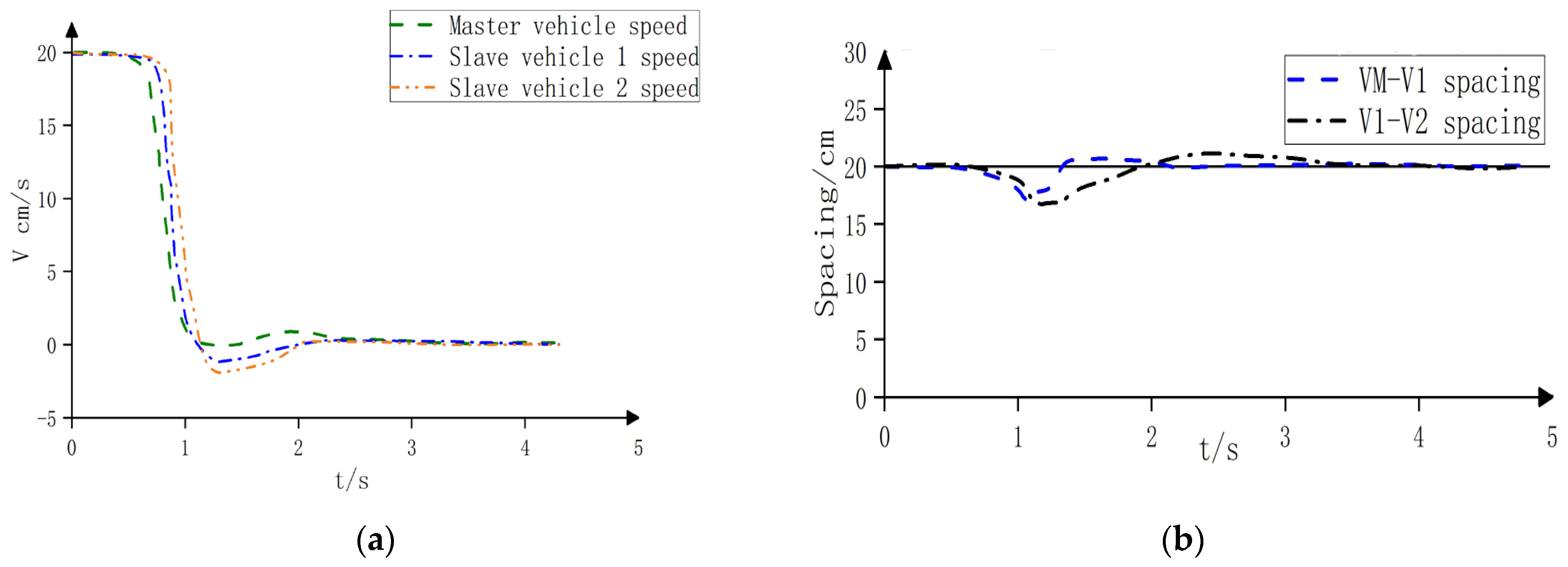
  • Scenario 1 (simulation of a clear road, convoy start-up to stable driving): the system is in a zero initial state, the master vehicle is started, and the slave vehicle is verified to follow the vehicle from a set initial speed to a stable following process.
  • Figure 15 shows that the front vehicle starts at the zero moment, and the rear vehicle quickly responds and maintains a similar speed to the front vehicle. After about 1.2 s, the start was completed, and the convoy formed an equidistant longitudinal formation stably in a short time, while the inter-vehicle distances all stably reached the preset desired values.
  • Scenario 2: (simulated road blockage) The system is in a non-zero initial state; there is an obstacle in front of the main vehicle, and the main vehicle is emergency braking to verify the safety of the following vehicle.
  • As can be seen from Figure 16, when the master vehicle stops, the speed of the master vehicle drops to zero, and the rear vehicle passes through the speed quickly and drops to zero; the overshooting amount is small, and after that, the error also decreases gradually, and finally converges to zero, and the distance between the front vehicle and the rear vehicle is always the same as the set distance to avoid the occurrence of the phenomenon of vehicle collision.
  • Experiments show that the vehicle formation control system exhibits good performance under different working conditions. The system is able to adjust the speed of the slave vehicles to follow the master vehicle when the convoy is starting and driving steadily; in an emergency braking situation, the system can detect and take braking measures in time to ensure driving safety. However, the communication delay of the system may lead to transient inconsistencies in speed control, which needs to be optimized in subsequent studies.

3.2. Vehicle Formation Operation Test in Complex ROAD Conditions

  • Figure 17 shows the experiment map. All the intelligent vehicles in the experiment satisfy the operation conditions, and the preset safety distance between the two workshops is 15 cm.
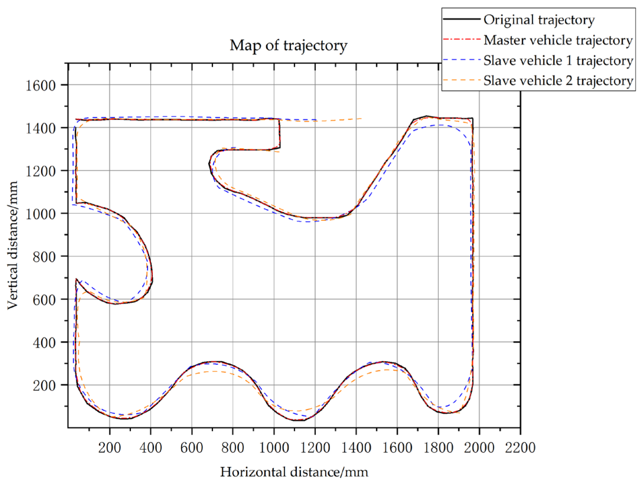
  • After testing, the vehicles execute the motion instruction issued by the main control unit with very high accuracy, so the authors will extract the PWM value of the vehicle servo at each moment and redraw the trajectory diagram of the three vehicles following the line through MATLAB. First of all, the kinematic analysis of the intelligent vehicle, according to the above derivation and the parameters of the vehicle model itself, to obtain the relationship between the linear and angular velocities of the intelligent vehicle and the PWM value due to the high frequency of the motion command issued by the central control unit, so the motion parameters of the vehicle in the interval between the two commands can be considered as unchanged, and thus the trajectory of the vehicle motion can be solved for each period. The combination of all segments of the trajectory can draw out the actual trajectory of the vehicle movement.
  • Figure 18 shows the coordinate position changes of the formation of intelligent vehicles during the movement process, where the horizontal and vertical axes represent different coordinate positions, respectively. The black trajectory represents the road line, the red trajectory represents the traveling path of the master vehicle, and the blue and orange trajectories represent the following path of the slave vehicles. From the figure, it can be observed that the master vehicle travels along the black roadway line, and the slave vehicles closely follow the master vehicle, and its path almost overlaps with the master vehicle’s trajectory. From the actual observation, the three intelligent vehicles eventually form a stable longitudinal formation, and the motion effect is consistent with the theoretical expectation.

4. Discussion

  • In the future, driven by 5G and 6G network technologies, intelligent vehicle communications will usher in multiple research directions and innovation opportunities. At the system design level, research on self-organizing networks [28] and edge computing technologies [29] to optimize dynamic topology management and low-latency data processing to ensure that intelligent vehicles can maintain efficient and stable communication capabilities in a variety of complex environments is important. In terms of communication protocols, new low-latency protocols and multihop communication methods will [30] enhance the reliability of communication between vehicles and between vehicles and infrastructure. In addition, multimodal sensing fusion [31] and sensor network optimization research will further enhance the accuracy of intelligent vehicles’ perception of the environment and the efficiency of data transmission so that they can more accurately identify traffic conditions, changes in road conditions, and other information to make smarter driving decisions, and these innovations and improvements will comprehensively enhance the communication capability and user experience of intelligent vehicles, and promote the development of intelligent transportation systems.
  • Based on intelligent network technology, internet-connected and self-driving vehicles can obtain more road information by utilizing advanced technologies (e.g., vehicle-to-vehicle communication, vehicle-to-infrastructure communication, and intelligent transportation systems). These rich communication methods provide an excellent advantage for intelligent vehicles to implement eco-driving strategies. Eco-driving strategies are an effective means to promote energy-efficient operation of intelligent vehicles by optimizing speed profiles. By collecting and analyzing traffic information (e.g., road conditions, traffic flow, traffic light signals, etc.), the vehicle control system can calculate an optimal speed change profile to drive as smoothly and efficiently as possible [32].
  • The eco-driving strategy can be realized by the real-time optimization control method. Real-time optimization focuses on timely adjusting the state of the intelligent vehicle so that it consumes the least amount of energy and reduces carbon emissions. Some studies have shown that eco-driving strategies can improve a vehicle’s fuel economy by as much as 25%. In this study, PID is used to control the speed change process of the master and slave vehicles, which realizes the linear motion of the queue vehicle with a smooth change of vehicle speed and reduces unnecessary acceleration, deceleration, and stopping, thus reducing energy consumption. The practice of eco-driving helps to promote the sustainable development of the automotive industry and contributes to the building of a greener, more environmentally friendly, and sustainable society [33].
  • Against the backdrop of increasing levels of intelligence, we must also think deeply about the ethical issues raised by vehicle fleet technology. In emergency situations, intelligent fleet systems must make quick decisions, for example, to protect passengers or pedestrians in the vehicle. This involves complex ethical judgments, and there are two main options for ethical decision-making: Personal Ethics Settings (PES) and Mandatory Ethics Settings (MES). Personal Ethics Setting allows the end user to control and set the vehicle’s behavior in emergencies based on personal morals and preferences. MES guides the vehicle in making decisions through predefined ethical settings without human intervention. However, it has the disadvantage that it is often difficult to make satisfactory choices in the face of complex road situations. PES and MES have advantages and disadvantages, and in the early stages, a combination of the two may be preferable. However, as the technology develops and the ethical framework improves, a gradual transition to a mature MES may be the best solution to the ethical dilemma. In the meantime, national laws should clearly define the responsible parties for accidents in such situations to ensure clarity and fairness in the attribution of responsibility. For data privacy, strict data protection regulations must be established to ensure the security and privacy of public information and to create a safe and trustworthy intelligent transportation environment for the public. These measures represent a prudent application of technology and a responsible attitude toward public safety and enhance public confidence in intelligent transportation technology.
  • In summary, realizing fully unmanned control of intelligent vehicle queues requires the joint efforts of the government, enterprises, research institutions, and the public. The government should provide policy support, enterprises should promote technology and applications, research organizations should provide technical support, and the public should actively participate and provide feedback. By building a cooperative ecology, we can work together to promote the development of autonomous driving technology.

5. Conclusions

  • In this paper, the hardware platform of the intelligent vehicle system and the software platform of the ZigBee network were established, and according to the requirements of the multi-intelligent vehicles following control system, the multi-sensor intelligent vehicle integrating Arduino as the core controller, processor module, four-channel infrared sensor module, photoelectric speed measurement module, ultrasonic distance measurement module, Bluetooth networking module, motor drive module, and the ZigBee communication used for the communication of intelligent vehicle workshop was established.
  • For the following problem in the multi-intelligent vehicles following control system, we constructed the tracking direction mechanism based on ultrasonic waves, designed the PID algorithm of a multi-intelligent vehicle following control, obtained the control method that can ensure the asymptotic stability of the system, obtained the real-time state information of all the intelligent vehicles through the monitoring platform on the mobile phone end, and monitored the motion state of the intelligent vehicles in real-time. The experimental results show that the control system designed in this paper achieves the desired control effect.
  • Due to the limitations of the design cycle and the current experimental conditions, some improvements still need to be made to this system. In this paper, we only briefly discuss the following problem of multi-intelligent vehicles. The experimental results show that the vehicle formation control system exhibits a good performance on straight roads. However, in the curved road section, our algorithm of using ultrasonic technology to assist direction correction, simplifying the complex road condition into straight road processing, applying the PID control strategy to keep the distance between the vehicles, and the phenomenon of convoy jitter can be observed, proving that our strategy still needs improvement. To improve the control effect and enhance the robustness of the vehicle following system, we plan to implement a more accurate following control strategy in future work. This system relies on the commands and states of the main vehicle, which constitutes a significant weakness. Once the main vehicle fails or the communication is interrupted, the whole formation may be in chaos or even unable to continue traveling. To solve this problem, more advanced synchronization control algorithms, such as time-based synchronization or distributed coherence control algorithms, can be introduced to reduce the dependence on the main vehicle. On the other hand, the scalability of the system is also limited. As the number of vehicles in the formation increases, communication delay and synchronization complexities rise dramatically. In addition, the research in this paper mainly focused on the longitudinal control of the vehicle following the system. However, lateral movements such as lane changing and steering are unavoidable during vehicle traveling. Therefore, the longitudinal and lateral coupling problem of vehicles will be the focus of the next research.

Author Contributions

Conceptualization, methodology, software, P.W. and T.O.; validation, P.W., T.O., S.Z., X.W. and Z.N.; formal analysis, P.W. and Z.N.; investigation, S.Z.; resources, Y.F.; data curation, T.O.; writing—original draft preparation, T.O., P.W. and S.Z.; writing—review and editing, P.W., T.O. and X.W.; visualization, X.W.; supervision, Y.F.; project administration, Y.F.; funding acquisition, Y.F. All authors have read and agreed to the published version of the manuscript.

Funding

This research was funded by Beijing Forestry University college student innovation and entrepreneurship project (X202310022203).

Data Availability Statement

The original contributions presented in the study are included in the article, further inquiries can be directed to the corresponding author.

Conflicts of Interest

The authors declare no conflicts of interest.

References

  1. Yang, L.; Zhao, X.; Wu, G.; Xu, Z.; Matthew, B.; Hui, F.; Hao, P.; Han, M.; Zhao, Z.; Fang, S.; et al. Review on connected and automated vehicles based cooperative eco-driving strategies. J. Traffic Transp. Eng. 2020, 20, 58–72. [Google Scholar]
  2. Xuan, J.Y.; Lu, G.; Wang, J.C. Vehicle following control system based on micro smart car. Inf. Control 2014, 43, 165–170. [Google Scholar]
  3. Yang, L. Design and Platform Implementation of Networked Following Control for Multi-Intelligent Car. Master’s Thesis, Shanxi University, Taiyuan, China, 1 June 2019. [Google Scholar]
  4. Alberto, B. Automatic Vehicle Guidance: The Experience of the ARGO Autonomous Vehicle; World Scientific: Singapore, 2023. [Google Scholar]
  5. Stentz, T.; Kelly, A.; Herman, H.; Rander, P.; Amidi, O.; Mandelbaum, R. Integrated Air/Ground Vehicle System for Semi-Autonomous Off-Road Navigation. In Proceedings of the AUVSI Symposium, Pittsburgh, PA, USA, 9–11 July 2002. [Google Scholar]
  6. Xu, C.Y.; Wang, B.R.; Ji, S.W. Study on View Field and Image Rectifying for Intelligent Vehicle. Gonglu Jiaotong Keji 2000, 5, 76–80. [Google Scholar]
  7. Hong, J.L.; Gao, B.Z.; Dong, S.Y.; Cheng, Y.F. Key Problems and Research Progress of Energy Saving Optimization for Intelligent Connected Vehicles. China J. Highw. Transp. 2021, 34, 304–336. [Google Scholar]
  8. Dey, K.C.; Yan, L.; Wang, X.; Wang, Y.; Shen, H.; Chowdhury, M.; Yu, L.; Qiu, C.; Soundararaj, V. A review of communication, driver characteristics, and controls aspects of cooperative adaptive cruise control (CACC). IEEE Intell. Transp. Syst. Conf. 2015, 17, 491–509. [Google Scholar] [CrossRef]
  9. Xu, Q.; Mak, T.; Ko, J.; Sengupta, R. Vehicle-to-vehicle safety messaging in DSRC. In Proceedings of the 1st ACM International Workshop on Vehicular Ad Hoc Networks, 1st ed.; Ken, L., Ed.; Association for Computing Machinery: New York, NY, USA, 2004; pp. 19–28. [Google Scholar]
  10. Xing, H.H.; Xu, Y.; Jiang, X.J.; Fu, Y.K. Research on Application of 5G Communication Technology in Intelligent Transportation System. Transp. Energy Conserv. Environ. Prot. 2023, 19, 120–126. [Google Scholar]
  11. Chen, X. Leader-Follower Formation Control of Mobile Robots with Prescribed Performance Guarantees. Master’s Thesis, South China University of Technology, Guangzhou, China, 18 April 2019. [Google Scholar]
  12. Xu, D. Research on Formation Control of Multi-Mobile Unmanned Vehicle Based on WSN. Master’s Thesis, Xi’an Technological University, Xi’an, China, 15 May 2018. [Google Scholar]
  13. Lin, Z.; Ding, W.; Yan, G.; Yu, C.; Giua, A. Leader-follower formationvia complex Laplacia. Automatica 2013, 49, 1900–1906. [Google Scholar] [CrossRef]
  14. Han, L. Research on Vehicle Formation Control Based on Robust Adaptivecontrol Algorithm. Master’s Thesis, Beijing Jiaotong University, Beijing, China, March 2015. [Google Scholar]
  15. Li, R.M.; Wei, L.Z. A control method of unmanned car following under time-varying relative distance and angle. Acta Autom. Sin. 2018, 44, 2031–2040. [Google Scholar]
  16. Deng, G.C. Research on Multi Vehicle Cooperative Control Technology of Unmanned. Master’s Thesis, University of Jinan, Jinan, China, 29 May 2022. [Google Scholar]
  17. Fernandes, P.; Nunes, U. Platooning with IVC-Enabled Autonomous Vehicles: Strategies to Mitigate Communication Delays, Improve Safety and Traffic Flow. IEEE Trans. Intell. Transp. Syst. 2012, 13, 91–106. [Google Scholar] [CrossRef]
  18. Zhao, Q.; Zheng, H. Safety spacing control of truck platoon based on emergency braking under different road conditions. SAE Int. J. Veh. Dyn. Stab. NVH 2022, 7, 69–71. [Google Scholar] [CrossRef]
  19. Maxim, A.; Lazar, C.; Caruntu, C.F. Caruntu Distributed model predictive control algorithm with communication delays for a cooperative adaptive cruise control vehicle platoon. In Proceedings of the 2020 28th Mediterranean Conference on Control and Automation, Saint-Raphaël, France, 15–18 September 2020. [Google Scholar]
  20. Zhao, D.; Dai, Y.; Zhang, Z. Computational Intelligence in Urban Traffic Signal Control: A Survey. IEEE Trans. Syst. Man Cybern. Part C (Appl. Rev.) 2012, 42, 485–494. [Google Scholar] [CrossRef]
  21. Akopov, A.S.; Beklaryan, L.A. Traffic Improvement in Manhattan Road Networks with the Use of Parallel Hybrid Biobjective Genetic Algorithm. IEEE Access 2024, 2, 19532–19552. [Google Scholar] [CrossRef]
  22. Tang, L.; Huang, W.; You, J. The Design of the Intelligent Car Based on the Arduino UNO and Lab VIEW. J. Phys. Conf. Ser. 2019, 1288, 012071. [Google Scholar] [CrossRef]
  23. Wang, K.; Jiang, F.C. Research on Cooperation Control of Multi—Communication Intelligent Vehicle Platoon. Bull. Sci. Technol. 2020, 36, 40–43. [Google Scholar]
  24. Lv, Z.C. Arduino Programming Foundation, 2nd ed.; Beihang University Press: Beijing, China, 2014. [Google Scholar]
  25. Cheng, C. Arduino Development Guide (AVR); China Machine Press: Beijing, China, 2012. [Google Scholar]
  26. Peng, Y. LabVIEW Virtual Instrument Design and Analysis; Tsinghua University Press: Beijing, China, 2011. [Google Scholar]
  27. Shen, J. Arduino and LabVIEW Development Combat; China Machine Press: Beijing, China, 2014. [Google Scholar]
  28. Liu, Y.M.; Li, X.; Ji, H. Key technology of network self-organization in 5G ultra-dense scenario. Telecommun. Sci. 2016, 32, 44–51. [Google Scholar]
  29. Najmul, H.; Yau, K.-L.A.; Wu, C. Edge computing in 5G: A review. IEEE Access 2019, 7, 127276–127289. [Google Scholar]
  30. Sarma, S.S.; Hazra, R.; Chong, P.H.J. Performance Analysis of DF Relay-Assisted D2D Communication in a 5G mm Wave Network. Future Internet 2022, 14, 101. [Google Scholar] [CrossRef]
  31. Wang, Y.; Ning, W.; Zhang, S.; Yu, H.; Cen, H.; Wang, S. Architecture and key terminal technologies of 5G-based internet of vehicles. Comput. Electr. Eng. 2021, 95, 107430. [Google Scholar] [CrossRef]
  32. Yang, J.; Zhao, D.; Jiang, J.; Lan, J.; Mason, B.; Tian, D.; Li, L. A Less-Disturbed Ecological Driving Strategy for Connected and Automated Vehicles. IEEE Trans. Intell. Veh. 2021, 8, 413–424. [Google Scholar] [CrossRef]
  33. Zhou, M.; Jin, H.; Wang, W. A review of vehicle fuel consumption models to evaluate eco-driving and eco-routing. Transp. Res. D Transp. Environ. 2016, 49, 203–218. [Google Scholar] [CrossRef]
Figure 1. Structure of intelligent vehicle information interaction system.
Wevj 15 00252 g001
Figure 2. Intelligent vehicle hardware overall design.
Wevj 15 00252 g002
Figure 3. The principle of the master vehicle microcontroller connected to peripherals.
Wevj 15 00252 g003
Figure 4. Ultrasonic transducer working schematic.
Wevj 15 00252 g004
Figure 5. Establishment of ZigBee wireless communication network.
Wevj 15 00252 g005
Figure 6. The principle of transparent transmission.
Wevj 15 00252 g006
Figure 7. Kinematic model of a four-wheel drive differential steering vehicle.
Wevj 15 00252 g007
Figure 8. Workflow of intelligent vehicle formation system.
Wevj 15 00252 g008
Figure 9. Master vehicle speed PID controller schematic.
Wevj 15 00252 g009
Figure 10. Fleet spacing PID controller schematic diagram.
Wevj 15 00252 g010
Figure 11. Ultrasonic Motion Control Diagram.
Wevj 15 00252 g011
Figure 12. Ranging Diagram.
Wevj 15 00252 g012
Figure 13. (a) Bluetooth APP display interface (b) Fleet status display interface.
Wevj 15 00252 g013
Figure 14. Multi-intelligent vehicles follow in formation.
Wevj 15 00252 g014
Figure 15. (a) Speed of vehicles (b) Spacing between vehicles.
Wevj 15 00252 g015
Figure 16. (a) Speed of vehicles (b) spacing between vehicles.
Wevj 15 00252 g016
Figure 17. Intelligent vehicle tracking map.
Wevj 15 00252 g017
Figure 18. Redrawn trajectories via MATLAB (version R2021b, Natick, MA, USA).
Wevj 15 00252 g018
Table 1. Sensor Instruction Parsing Diagram.
LS [1]LS [2]RS [1]RS [2]Motion State
0010Turn right slightly
0100Turn left slightly
0011Turn right
1100Turn left
0001Turn right sharply
1000Turn left sharply
0110Go straight
Table 2. Control Command Resolution Table.
|v|(cm/s) |w|(rad/s)(Left/Right Motor) PWMCommand
200150150Go ahead
2.15.46210−180Turn right
2.15.46−180210Turn left
13.60−90−90Go back
0000Stop
8.40.890150Narrow left
8.40.815090Narrow right
05.87−210210Sharp left
05.87210−210Sharp right
Table 3. APP Manual Takeover Interface Menu.
ButtonInstructionFunction
Go ahead1Control the vehicle forward movement
Turn right2Control the vehicle to turn right
Turn left3Control the vehicle to turn left
Go back4Control the vehicle to move backwards
Stop5Control the vehicle stop
Automatic routing10Autonomous command
Manual takeover11Remote command
Disclaimer/Publisher’s Note: The statements, opinions and data contained in all publications are solely those of the individual author(s) and contributor(s) and not of MDPI and/or the editor(s). MDPI and/or the editor(s) disclaim responsibility for any injury to people or property resulting from any ideas, methods, instructions or products referred to in the content.

