Article

An Automatic Emergency Braking Control Method for Improving Ride Comfort

1
School of Vehicle Engineering, Chongqing University of Technology, Chongqing 400054, China
2
Key Laboratory of Advanced Manufacturing Technology for Automobile Parts, Ministry of Education, Chongqing 400054, China
*
Author to whom correspondence should be addressed.
World Electr. Veh. J. 2024, 15(6), 259; https://doi.org/10.3390/wevj15060259
Submission received: 10 April 2024 / Revised: 5 June 2024 / Accepted: 11 June 2024 / Published: 14 June 2024

Abstract

:
The contribution of this paper is to present an automatic emergency braking (AEB) optimized algorithm based on time to collision (TTC) and a professional driver fitting (PDF) braking pattern. When the TTC value is less than the given threshold, the PDF control algorithm will be started, and vice versa. According to the standard test scenarios for passenger cars and commercial vehicles, the simulation analysis on the AEB systems using four different control algorithms, namely TTC, quadratic curve deceleration, PDF and proposed optimized control algorithm, is conducted, respectively. The results show that the proposed optimization algorithm can both meet the standard requirements and improve the ride comfort. While ensuring collision avoidance with the preceding vehicle, the control algorithm proposed in this study offers better braking comfort compared to the TTC algorithm and the quadratic curve deceleration algorithm. Additionally, it provides a more appropriate stopping distance compared to the PDF algorithm.

1. Introduction

1.1. Motivations

Intelligent vehicle technology is currently gaining substantial traction as a focal point of research. As one of the representative functions, automatic emergency braking (AEB) control systems will play a very important role in promoting the popularization of automatic driving technology. Extensive analysis of accident databases underscores the imperative for AEB systems to effectively mitigate property damage and personal injuries in traffic accidents along the longitudinal direction. Therefore, the research on AEB becomes more and more important [1,2,3,4,5,6,7].

1.2. State of the Art

There are two main types of AEB research based on simple mathematical models, one is based on safe distance model and the other is based on time-to-collision (TTC) model. Neither of them explicitly considered passenger comfort in the design of the AEB controller. Ref. [8] presented the Mazda control algorithm, which integrates four key technical elements. In contrast, ref. [9] introduced the Berkeley algorithm, incorporating an estimator for tire–road friction, and compared it with both Mazda and Honda control methods. In [10], a vehicle adaptive cruise control algorithm was proposed, which incorporated a safe distance model. Conversely, the TTC model gained more popularity due to its simplicity, achieving significantly higher true-positive rates compared to other algorithms assessed. Experimental results reported in [11] suggested that the decision to start braking and the regulation of braking were influenced by TTC data extracted from the optic flow field. In a laboratory simulation [12], the driver’s estimation of the time to collision was investigated using video clips depicting a following vehicle approaching a preceding vehicle. In [13], a hierarchical braking collision avoidance strategy was introduced based on the time-to-collision (TTC) model, and the parameters of a TTC control algorithm concerning rear-end collisions were discussed in [14].
One obvious issue with the AEB control algorithms mentioned above is their poor braking comfort, which has a significant influence on the users’ experience. Due to a sudden change in braking deceleration, it had caused great longitudinal impact on passengers, which would undoubtedly affect people’s acceptance of this function. This may be the principal reason why people are reluctant to enable this function. Therefore, it is necessary to explore a humanized intelligent automatic collision avoidance control method. In fact, AEB control algorithms focus on two key elements, namely when to trigger the deceleration action, and how to determine the deceleration mode of the system [15]. Ref. [16] examined the effect of time headway on the key variables of the driver behavior theory, i.e., task difficulty, risk, effort and comfort. Ref. [17] investigated how safety messages influence driving behavior and proposed that identical messages could yield contrasting outcomes depending on the context. Ref. [18] investigated the crash avoidance behavior of drivers under varying degrees of situational urgency was investigated by means of a high-fidelity driving simulator. Ref. [19] provided evidence that both the onset and regulation of braking were influenced by the time to collision (TTC) when the preceding vehicle initiated braking across various time-headway (THW) conditions. Ref. [20] designed an algorithm for online risk assessment in forward collision avoidance systems. Ref. [21] devised a model for braking behavior and integrated it into an automatic emergency braking system. This model leverages the emergency braking patterns observed in professional drivers to classify risk levels effectively. It introduced a logarithmic expression for the parameter K to describe the distance between the rear vehicle and the front vehicle. Although the professional driver fitting (PDF) algorithm could improve the ride comfort of vehicles during collision avoidance, its problem lay in the fact that its trigger time was too early, resulting in a relatively large stop spacing, and also affecting the road utilization.

1.3. Contributions

Given the limitations observed in current AEB control algorithms, the areas that need to be improved are as follows: on one hand, it is necessary to improve the vehicle ride comfort during automatic emergency braking, and use the personified emergency braking characteristics to make it easy for people to accept; on the other hand, it is also necessary to improve the road utilization to avoid excessive stop spacing caused by the early trigger of the AEB control system. Taking into account the aforementioned factors, in response to these concerns, the article suggests an enhanced AEB control algorithm. Specifically, when the time to collision (TTC) falls below a predefined threshold, the PDF control switch is deactivated to prevent a collision with the vehicle ahead. This paper’s key contribution lies in its proposal of an enhanced automatic emergency braking control algorithm designed for rear-end collision prevention, by leveraging the strengths of both the time-to-collision (TTC) algorithm and the PDF algorithm. While prioritizing braking comfort, the proposed optimized AEB control system effectively reduces stopping distances by preventing premature triggering. In addition, it ensures compliance with Chinese safety standards.

1.4. Structure Overview

The article is structured as follows. (1) Introduction: This section presents an overview of the topic. (2) Algorithm Presentation: The second part details the TTC algorithm, quadratic curve deceleration algorithm, the professional driver fitting (PDF) algorithm, and the enhanced AEB algorithm. (3) Simulation Comparison: The third part provides some comparative analysis of the four aforementioned algorithms, employing existing standard test scenarios for both passenger cars and commercial vehicles. (4) Conclusion: The final section summarizes the key findings and conclusions drawn from the study.

2. AEB Control Algorithms

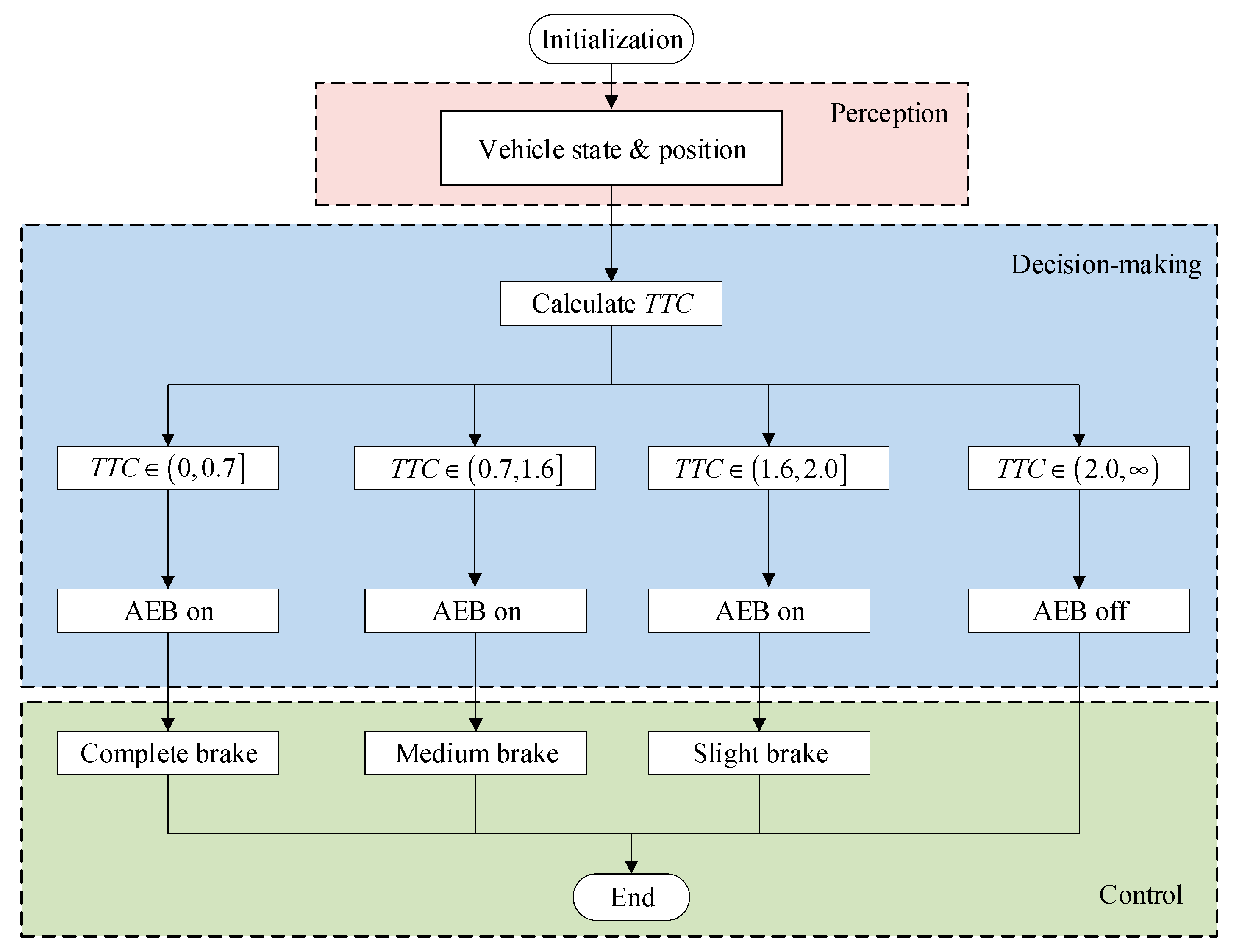
2.1. TTC Control Algorithm

In the realm of rear-end collision avoidance control systems, the time-to-collision (TTC) algorithm is frequently favored due to its simplicity. In the TTC control algorithm described in this paper, three levels of braking modes are used, as shown in Figure 1. (1) when the time-to-collision value is more than 2 s, the AEB control system is inactive; (2) When the time to collision falls within the range of 1.6 s to 2 s, the AEB control system applies a mild brake action; (3) In the case where the time to collision ranges from 0.7 s to 1.6 s, the AEB control system initiates moderate braking while preserving partial steering capability. (4) When the TTC drops below 0.7 s, the system engages a complete brake action [13].

2.2. Quadratic Curve Deceleration Control Algorithm

Although the time-to-collision (TTC) control algorithm prevents collisions effectively, sudden changes in acceleration during the braking process often cause discomfort for passengers. By performing quadratic curve planning on the acceleration to make the derivative of acceleration (jerk) constant, the corresponding braking control law can be obtained, as shown in Equations (1) and (2).
a ( t ) = const × ( t t b ) a ˙ ( t ) = const v ( t ) = v 0 + t b t const × t d t s ( t ) = s 0 + t b t v ( t ) d t , t t b , t f
v ( t f ) = 0 s ( t f ) = d s a f e , t = t f
where the variable a is the vehicle longitudinal acceleration, v0 denotes the vehicle initial speed, s0 denotes the longitudinal initial displacement between the following vehicle (ego vehicle) and the leading vehicle (obstacle vehicle), tb denotes the moment when the AEB system initiates its operation, tf denotes the moment when the AEB system ceases its operation, and dsafe is the safe distance.

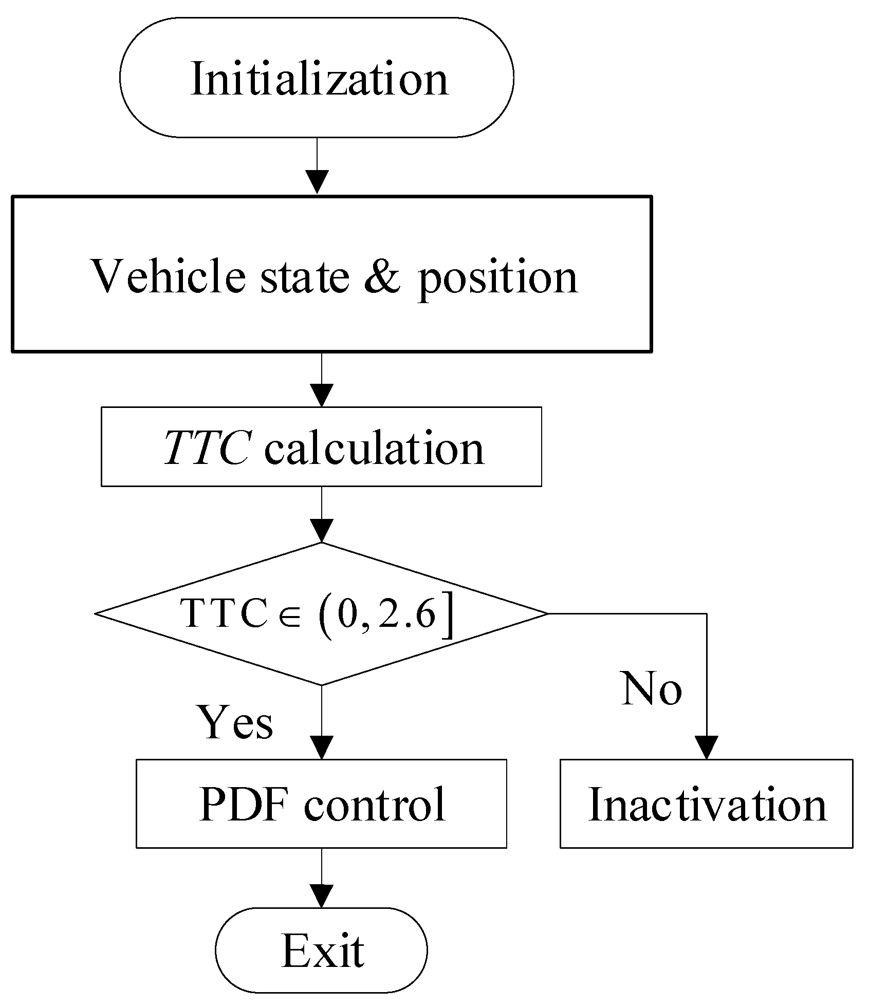
2.3. PDF Control Algorithm

The emergency braking control algorithm of professional driver fitting mainly includes two aspects: the first part is the judgment of the initial braking time, and the second part is the application of the deceleration control pattern. Through the test of professional driver’s emergency braking, the above two aspects of information can be extracted and fitted, and further formulated, which can be applied to the control algorithm design for automatic emergency braking control system finally.

2.3.1. Judgment of Initial Braking Time

Through the analysis of professional driver behavior, the following collision risk index ϕ is proposed by Equation (3). The velocity of the front vehicle, the relative velocity, and the gap between the two vehicles are represented by vL, vr, and d, respectively. The evaluation index for measuring the proximity of two vehicles, denoted as KdB_c, is introduced in dB, and it can be computed using Equations (4) and (5) [21]. The trigger time of the professional driver’s last-second braking can be formulated on the premise that ϕ is equal to zero. The fitting constants of the PDF algorithm are α = 0.2, β = −22.66, and γ = 74.71.
ϕ v L , v r , d = K d B _ c ( α ) β log 10 d γ
K d B _ c = 10 log 10 ( Δ ) sgn ( v r + α v L ) Δ 1 0 Δ < 1
Δ = 4 × 10 7 × v r + α v L d 3

2.3.2. Deceleration Control

Once the time for triggering the brakes is established, the vehicle longitudinal deceleration can be controlled by Equation (6), where Pbrake_out is the longitudinal acceleration output, kp is the feedback gain and the scalar vrd(t) denotes the desired relatively velocity defined by Equation (7). The brake trigger time tbi can be solved by Equation (3). The variable δ(t) is defined by Equation (8), where dconv is the target converged gap. When vr is equal to or below zero, the automatic braking would be turned off. The details can be referred to in [21]. In Figure 2, the PDF control logic diagram is shown.
  P brake _ out = k p v r d ( t ) v r ( t )
v r d ( t ) = v r ( t b i ) δ 3 ( t ) exp 3 × 1 δ 3 ( t )
δ ( t ) = d ( t ) d c o n v d ( t b i ) d c o n v

2.4. Proposed Control Algorithm

Previous studies had shown that the TTC control algorithm is more radical [13,14]. Although it could avoid collision effectively, the sudden change in vehicle longitudinal acceleration may have a great influence on the comfort of passengers. Regarding the PDF control algorithm, it is developed based on the emergency braking behaviors exhibited by experienced drivers. Although its comfort has been greatly improved, the braking trigger time is too early and the stop spacing is always too large. Therefore, this paper proposes an optimized control algorithm by combining with the two control algorithms above. The PDF control switch will be deactivated when the TTC value falls below a specific threshold, 2.6 s in this study [22]. The control flowchart is depicted in Figure 3 below.

3. Simulation and Analysis
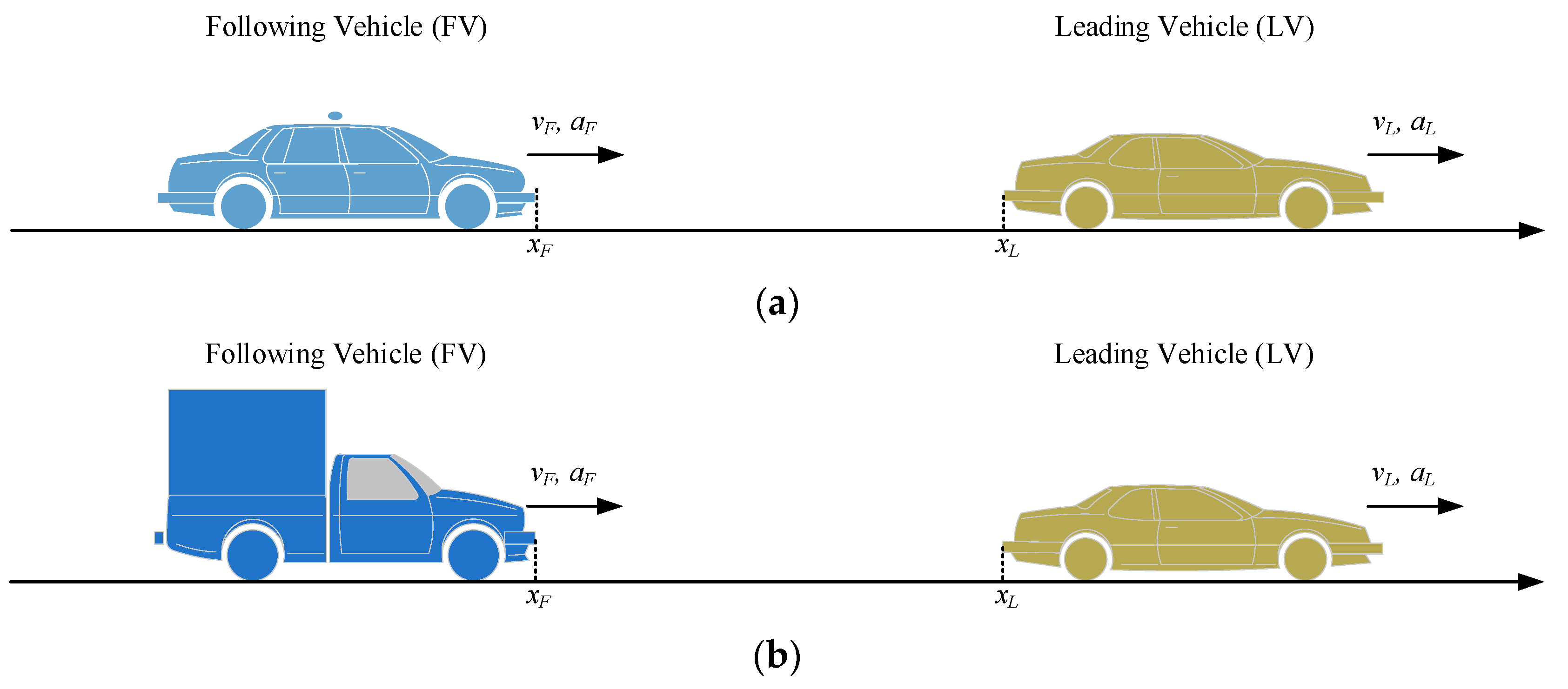
3.1. Test Scenarios

According to performance requirements and test methods for advanced emergency braking system (AEBS) of passenger cars [23] and performance requirements and test procedures for advanced emergency braking system of commercial vehicle [24], two distinct sets of test scenarios are devised for passenger cars and commercial vehicles, respectively, as shown in Figure 4. Both test standards require testing on surfaces with high adhesion. Therefore, in this simulation, the road surface is set to high adhesion (u = 1.0), temporarily not considering other adhesion conditions. For the point mass model, the control algorithm directly provides the acceleration output without considering the impact of vehicle mass.
For passenger cars, the test scenarios consist of three types: (1) car-to-car rear stationary (CCRs), (2) car-to-car rear moving (CCRm), and (3) car-to-car rear braking (CCRb). Table 1 details the test scenarios above. For commercial vehicles, the scenarios encompass only CCRs and CCRm, as outlined in Table 2. Using the point mass model, it can be solved in Matlab/Simulink R2022b using the fourth Runge–Kuta method with a major time step of 0.001 s.

3.2. Test Results

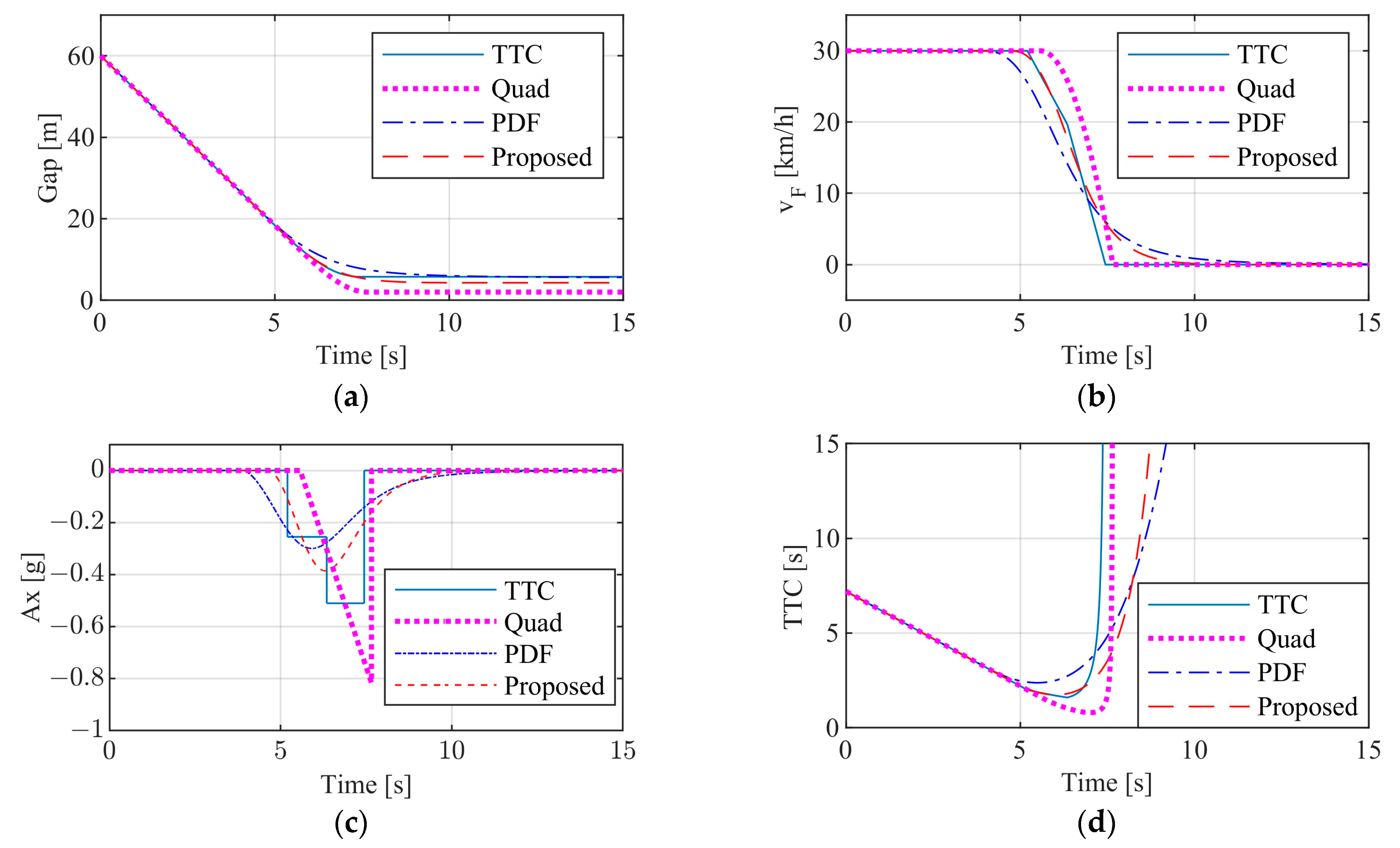
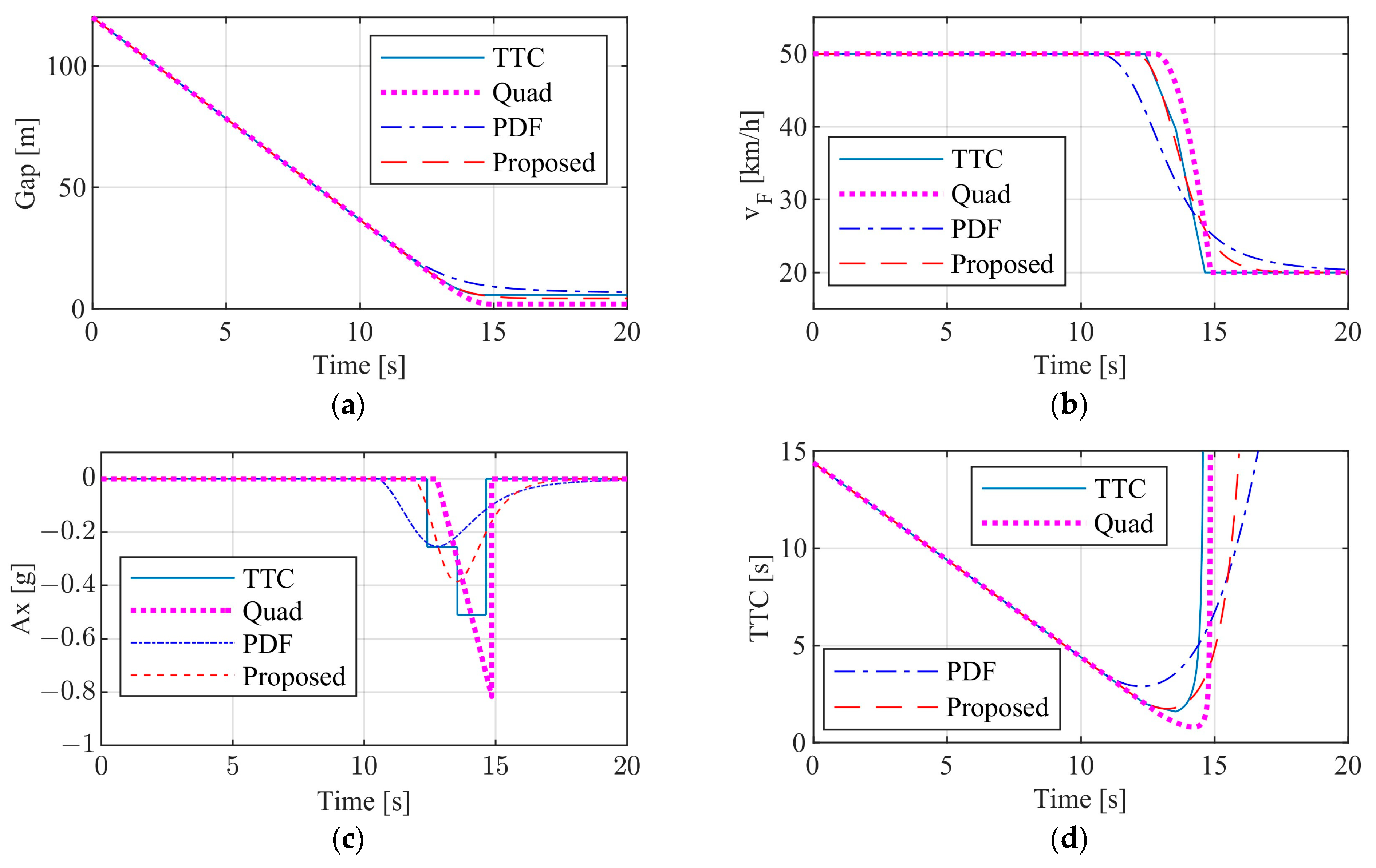
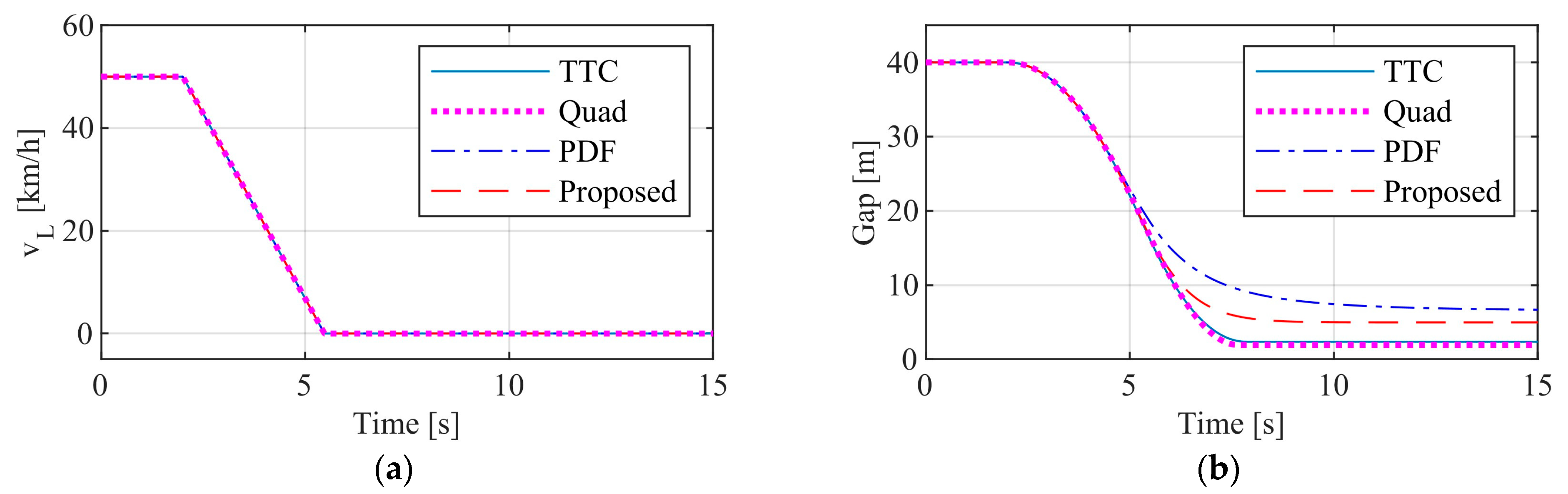
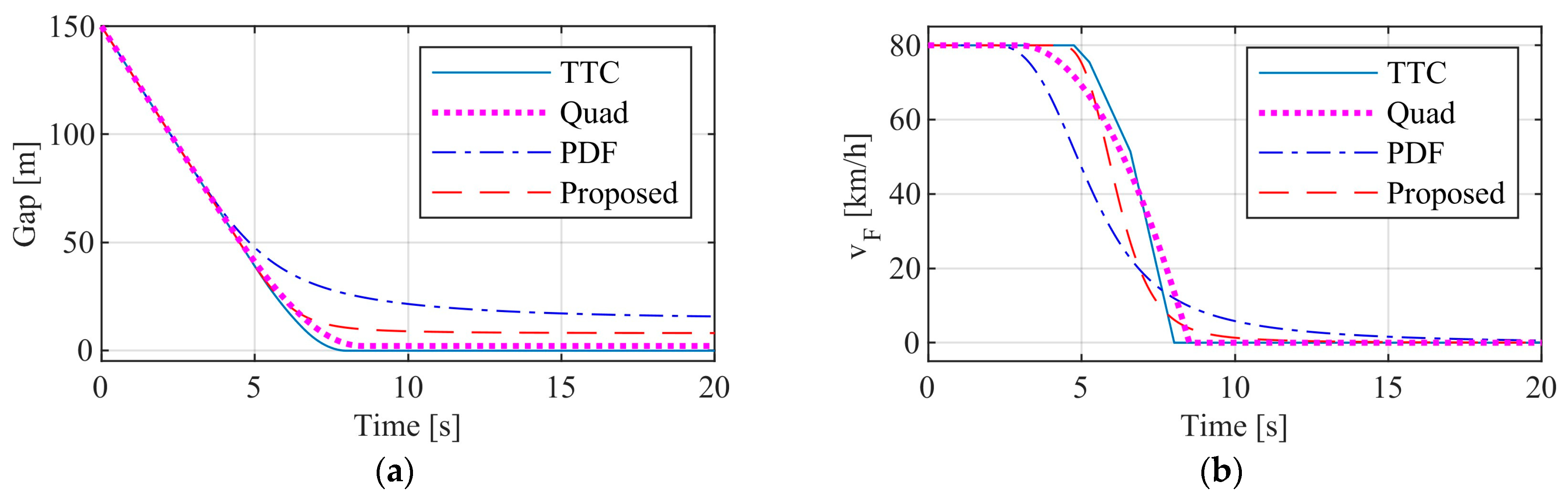
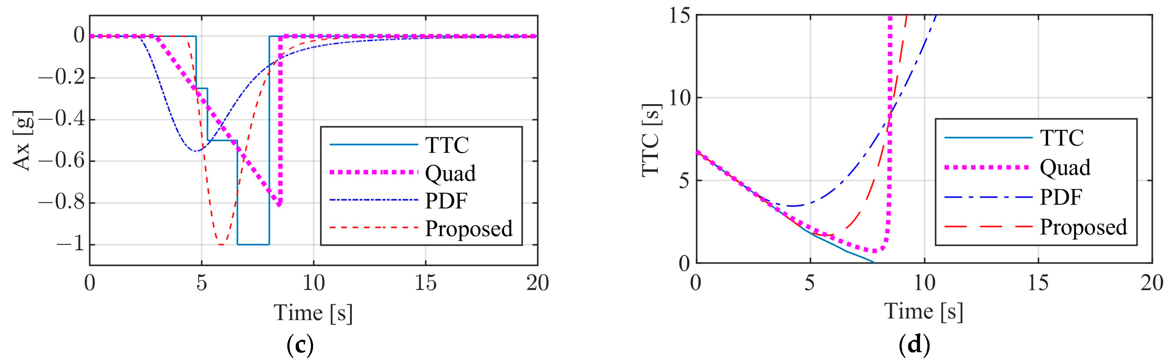
3.2.1. Test Results of Passenger Car

The test results of passenger cars are shown in Figure 5, Figure 6 and Figure 7. Based on the test scenarios provided in Table 1, the test results for CCRs, CCRm and CCRb, are presented, respectively.
Figure 5a–d show the variation of distance between the front and rear vehicles, the rear vehicle speed, the rear vehicle longitudinal acceleration and TTC values, respectively. Under this CCRs working condition, the front vehicle is stationary 60 m in front of the rear vehicle. The rear vehicle approaches the front vehicle at an initial speed of 30 km/h. It is evident that the vehicle equipped with any of the four control systems can prevent collisions effectively. The stopping distances achieved by the TTC, the Quad, the PDF and that of the proposed enhanced control system are about 5.7 m, 2 m, 5.7 m and 4.28 m. The AEB start-up times, in order from earliest to latest, are the PDF, the enhanced control system, the TTC, and the Quad, at the moment of 3.97 s, 4.71 s, 5.2 s and 5.57 s, respectively. The maximum values of longitudinal acceleration of the rear vehicle are about 0.3 g, 0.4 g, 0.5 g and 0.8 g, respectively. Compared with the TTC, the longitudinal deceleration of the PDF and enhanced control systems changes more smoothly, and that of the Quad increases gradually to its maximum. The minimum TTC values for the four dissimilar control systems are 1.6 s, 2.38 s, 1.75 s and 0.8 s, respectively. All the four AEB control systems can avoid collisions successfully under this test scenario.
In the CCRm working condition, the front vehicle is travelling on a straight line at 20 km/h while the rear vehicle is approaching the front vehicle at 50 km/h. The initial spacing between the front and rear vehicles is 120 m. Figure 6a–d show the responses of the two vehicles’ spacing, the rear vehicle speed, the rear vehicle longitudinal acceleration, and TTC values, respectively. The results show that any of the four control systems are effective in avoiding collisions. The stopping distances for the TTC, Quad, PDF and enhanced control systems are 5.77 m, 2 m, 6.92 m and 4.29 m, respectively. The AEB start-up times (from earliest to latest) are as follows: 10.55 s for the PDF, 11.89 s for the proposed enhanced control system, 12.4 s for the TTC, and 12.77 s for the Quad. The minimum TTC values for the four dissimilar control systems are 1.6 s, 2.89 s, 1.74 s and 0.8 s respectively.
In the CCRb working condition, at t = 0 s, the front vehicle is travelling on a straight line at 50 km/h and the rear vehicle is approaching the front vehicle at an initial speed of 50 km/h. At t = 2 s, the front vehicle decelerates at a constant deceleration of 0.4 g. The initial spacing between the front and rear vehicles is 40 m. Figure 7a–d show the responses of the two vehicles’ spacing, the rear vehicle speed, the rear vehicle longitudinal acceleration, and the TTC values, respectively. The results show that any of the four control algorithms are effective in avoiding collisions. The stopping distances for the TTC, Quad, PDF and proposed enhanced control systems are 2.36 m, 1.92 m, 6.69 m and 4.96 m, respectively. The AEB start-up times (from earliest to latest) are as follows: 4.03 s for the PDF, 4.13 s for Quad, 4.62 s for the enhanced control system, and 4.9 s for TTC. The minimum TTC values for the four dissimilar control systems are 0.97 s, 0.75 s, 1.51 s and 2.19 s, respectively.
The test results from three CCR scenarios reveal notable enhancements in brake comfort with the proposed enhanced control system compared to the TTC, evident in the longitudinal deceleration response. Furthermore, the proposed enhanced control system has substantially decreased stop spacing compared to the PDF, thus enhancing road utilization. Additionally, it is worth noting that the Quad exhibits the highest peak deceleration.

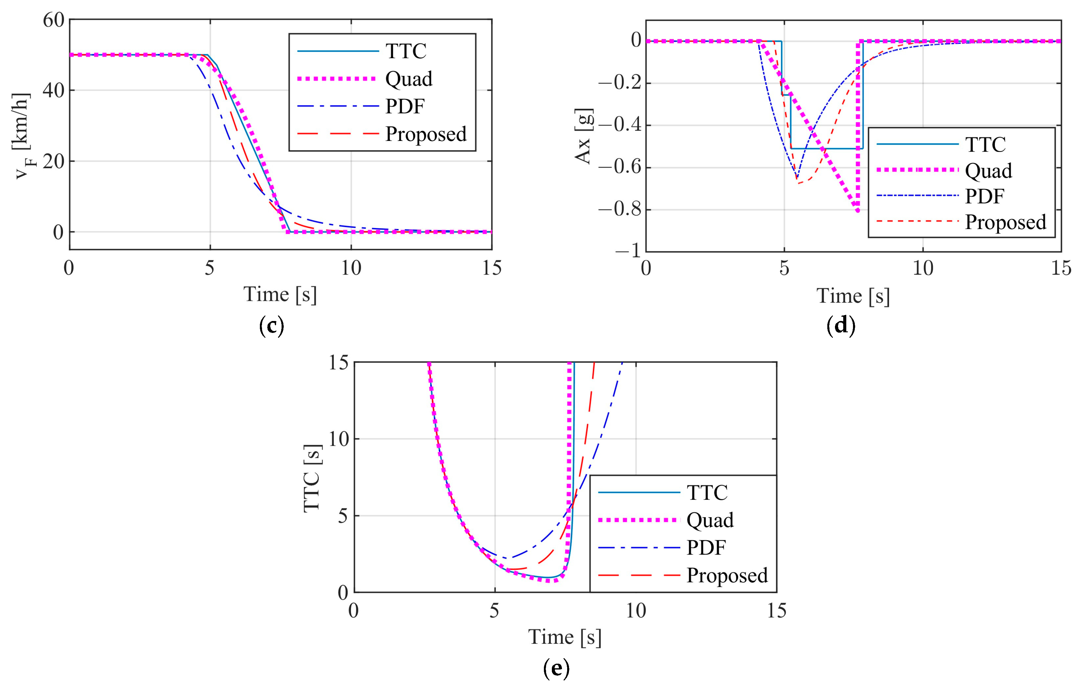
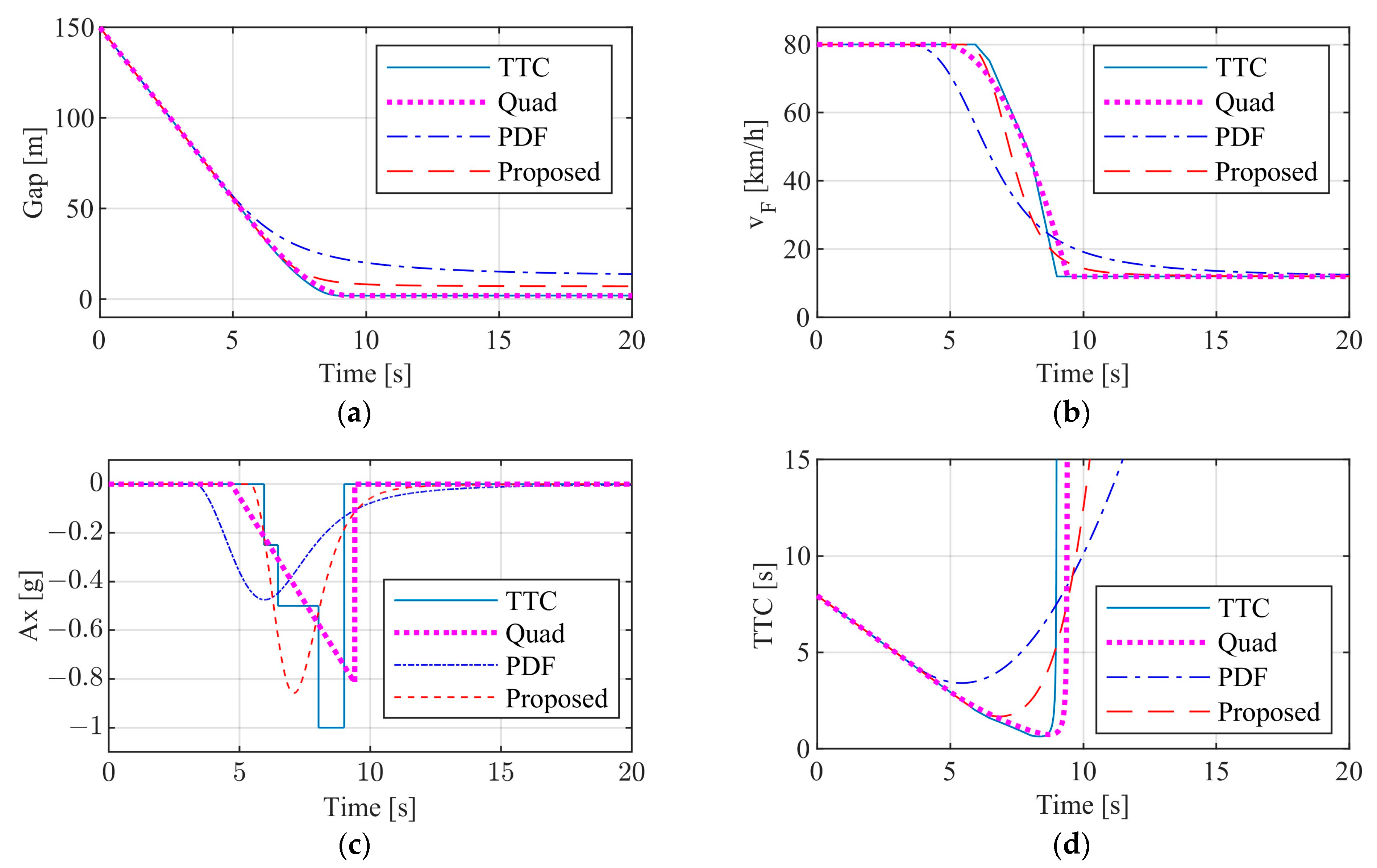
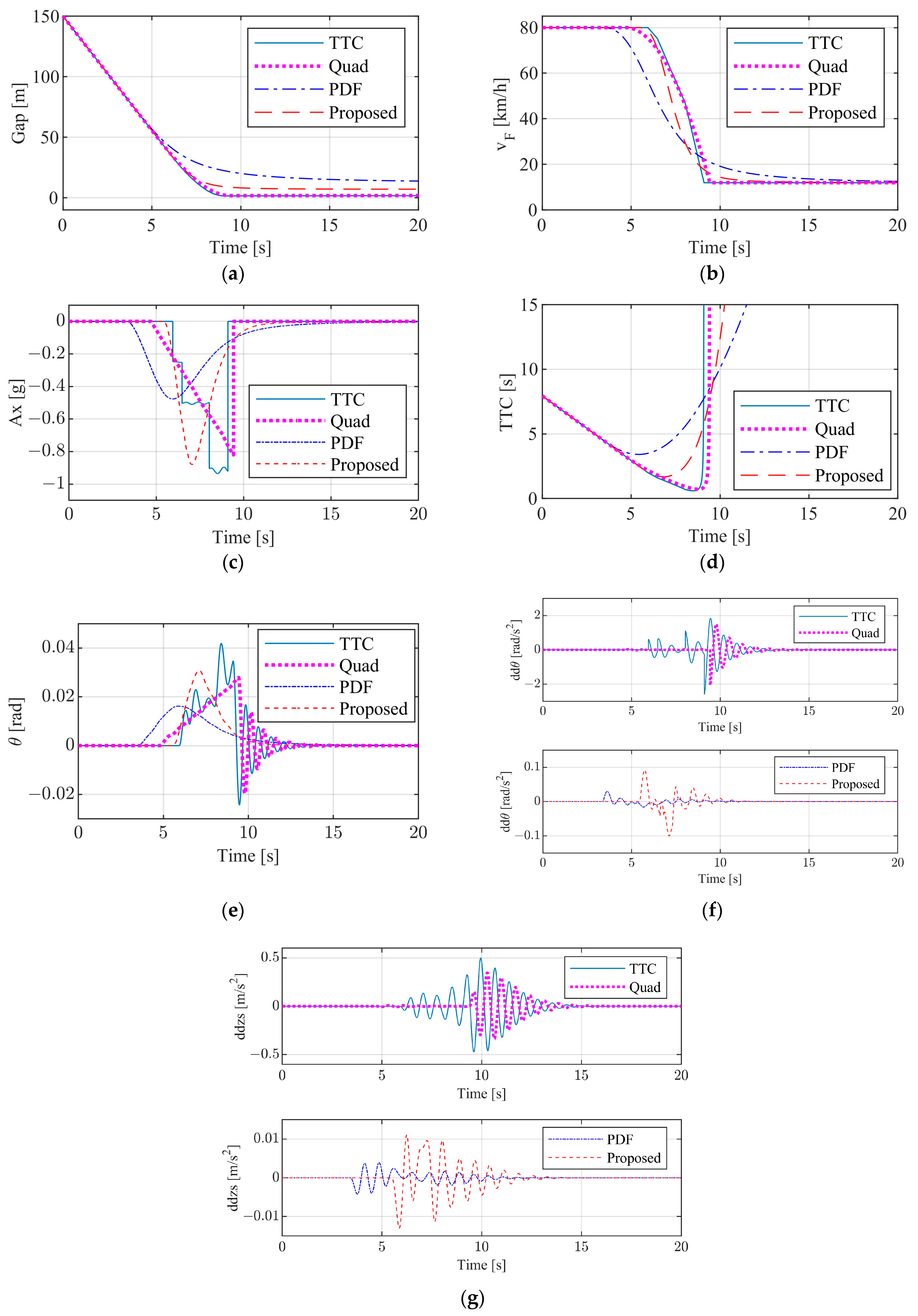
3.2.2. Test Results of Commercial Vehicle

The test results of commercial vehicles are shown in Figure 8, Figure 9 and Figure 10 according to the test scenarios listed in Table 2.
Figure 8a–d show the variation of distance between the front and rear vehicles, the rear vehicle speed, the rear vehicle longitudinal acceleration and TTC values, respectively. Under this CCRs working condition, the front vehicle is stationary 150 m in front of the rear vehicle. The rear vehicle approaches the front vehicle at an initial speed of 40 km/h. It is evident that vehicles equipped with any of the four control systems can effectively prevent collisions. The stopping distances achieved by the TTC, Quad, the PDF and that of the proposed enhanced control system are about 6.22 m, 1.98 m, 7.76 m and 5.15 m. The AEB start-up times, in order from earliest to latest, are the PDF, the enhanced control system, the Quad, and the TTC at the moment of 9.86 s, 11.0 s, 11.47 s and 11.5 s, respectively. The corresponding TTC values are 3.64 s, 2.5 s, 2.03 s and 2.0 s, which can be seen in Figure 8d. The PDF and the Quad demonstrate maximum longitudinal accelerations of approximately 0.36 g and 0.8 g, respectively, while the other two control systems exhibit accelerations of around 0.5 g. In comparison to the TTC, the longitudinal deceleration of the PDF and proposed enhanced control systems changes more smoothly, while the deceleration variation of the Quad is relatively uniform.
Figure 9a–d show the variation of distance between the front and rear vehicles, the rear vehicle speed, the rear vehicle longitudinal acceleration and TTC values, respectively under the CCRs working condition. The difference with Figure 8 is that the initial speed of the rear vehicle changes from 40 km/h to 80 km/h. It can be clearly seen that the rear vehicle with the TTC control system collides with the front vehicle at approximately 7.8 s, when the rear vehicle’s speed has been reduced by the AEB control system to 7.7 km/h. With any of the other three control systems, the rear vehicle can avoid the collision effectively. The post-stopping front and rear vehicle distances for the Quad, PDF and the proposed enhanced control system are 2.0 m, 15.8 m and 8.0 m, respectively. From Figure 9c,d, it can be observed that the AEB start-up time occurs earliest for the PDF, followed by the Quad, the proposed enhanced control system, and finally the TTC, at the moment of 2.09 s, 2.96 s, 4.25 s and 4.72 s, respectively. The corresponding TTC values are 4.66 s, 3.79 s, 2.5 s and 2.0 s, respectively. In general, the proposed enhanced control system demonstrates superior overall capabilities, which can improve the vehicle ride comfort greatly on the premise of successful collision avoidance.
Figure 10a–d show the variation of distance between the front and rear vehicles, the rear vehicle speed, longitudinal acceleration and TTC values, respectively under the CCRs working condition. The sole distinction from Figure 9 is that the front vehicle is no longer stationary but instead travels on a straight line at 12 km/h. The results show that any of the four control algorithms are effective in avoiding collisions. The stopping distances achieved by the TTC, Quad, the PDF and that of the proposed enhanced control system are about 2.09 m, 2 m, 13.97 m and 7.2 m, respectively. From Figure 10c,d, it can be observed that the AEB start-up time occurs earliest for the PDF, followed by the Quad, the enhanced control system, and finally the TTC, at the moment of 3.35 s, 4.68 s, 5.4 s and 5.93 s respectively. The corresponding TTC values are 4.59 s, 3.26 s, 2.54 s and 2.0 s, respectively, which can be seen from Figure 10d. The maximum longitudinal acceleration for the PDF, Quad, the proposed, and TTC are approximately 0.47 g, 0.8 g, 0.84 g, and 1.0 g, respectively. In contrast to the TTC, the longitudinal deceleration of the remaining three control systems exhibits a more gradual transition.
Figure 11 similarly displays the vehicle responses under the CCRm working condition. The simulated working conditions are the same as Figure 10, but the vehicle model used is different. The former uses the previously established 18 DOF model [25], while the latter uses a point mass model. For the 18DOF vehicle model, variations in vehicle mass are also temporarily not considered. The specific parameters for the 18DOF vehicle model are listed in Table 3. The 18 DOF can consider more performance indexes, such as vehicle body pitch angle and vertical vibration acceleration of vehicle center of mass. Figure 11a–d show the variation of distance between the front and rear vehicles, the rear vehicle speed, the rear vehicle longitudinal acceleration, TTC values, pitch angle of vehicle body, pitch angular acceleration of vehicle body and vertical vibration acceleration of vehicle center of mass under the CCRm working condition. It is evident that the simulation results of the 18 DOF model closely resemble those of the particle model. There is a slight fluctuation in the longitudinal acceleration of the TTC control system, which is due to the fluctuation of the vertical load on the wheels caused by the body pitch motion during the braking process. The peak pitch angle, from large to small, is 0.04 rad for the TTC control system, approximately 0.03 rad for the Quad and proposed enhanced control systems, and 0.016 rad for the PDF. The peak pitch angular acceleration of the TTC and Quad are about 2 rad/s2, and those of the proposed and the PDF are 0.1 rad/s2 and 0.03 rad/s2, respectively. The response of the vertical vibration acceleration of the center of mass is also relatively similar, from large to small, is the TTC, the Quad, the proposed and the PDF.
From the simulation results of commercial vehicles, it is observed that the braking acceleration of the TTC control system exhibits step changes, resulting in poor comfort during the emergency braking process. Considering the PDF control system, which fits the characteristics of professional drivers, the changes in braking acceleration are relatively smooth, leading to significant improvements in braking comfort, although with a larger stopping distance. The proposed control system can fully leverage the advantages of both the TTC and PDF methods, ensuring good comfort and appropriate stopping distance during emergency braking. The quadratic deceleration control algorithm, due to not considering the constraints on deceleration at the end of braking, shows uniform acceleration changes during braking but has a noticeable sudden change in acceleration at the end of braking, adversely affecting braking comfort. Additionally, the simulation results of the 18DOF model are basically consistent with those of the point mass model. The changes in other performance indicators, such as vehicle body pitch angle, pitch angular acceleration and vertical vibration acceleration, further verify that the proposed control algorithm improves braking comfort compared to the TTC and Quad algorithms. The proposed algorithm significantly improves comfort during emergency braking; however, it is based on the assumption that road surface adhesion conditions are continuous and non-abrupt. Further validation is required to assess the effectiveness of the algorithm on non-uniform adhesion surfaces.
Through the analysis presented in this study, it is evident that appropriate early braking and optimized braking methods can improve the braking comfort significantly. In the research of autonomous driving or advanced driver assistance systems, enhancing the comfort of emergency braking can make these technologies more acceptable to people. After all, safety does not refer to the vehicle behaving in a safe manner but to the passengers feeling that it does. Therefore, in the process of developing automatic emergency braking test standards, in addition to the requirement to avoid collisions, the evaluation of braking comfort can also be considered. By doing so, the designed intelligent vehicles may become more trustworthy to the public.

4. Conclusions

This paper introduces an enhanced control algorithm for automatic emergency collision avoidance, leveraging the strengths of professional drivers’ emergency braking behavior and the TTC control algorithm. Through standardized test scenarios involving both passenger cars and commercial vehicles, it conducts simulation-based comparisons and analyses of four distinct control algorithms. The findings indicate that the proposed enhanced control algorithm fulfills the criteria outlined by both standards. Moreover, in comparison to the other three control algorithms, the proposed control method not only guarantees successful collision avoidance across diverse scenarios but also substantially enhances vehicle ride comfort, reduces the stop spacing and enhances the road utilization.
It is worth noting that this study relied solely on simulation methods to compare and analyze AEB control algorithms on uniform straight roads for both passenger and commercial vehicles. These findings lack validation with real-world data, and actual driving performance may differ significantly from the simulation results. Therefore, the proposed algorithm requires further experimental validation. Additionally, other scenarios involving emergency braking on non-uniform road surfaces or curves should also be considered for future research. It is also necessary to investigate the influence of vehicle masses on the AEB algorithm.

Author Contributions

Conceptualization, F.L.; methodology, formal analysis, F.L. and J.L.; software, validation, J.L. and Y.H.; writing, F.L. and J.L.; supervision, project administration, F.L. All authors have read and agreed to the published version of the manuscript.

Funding

This work was supported by Chongqing Technical Innovation and Application Development Special Project (CSTC2021jscx-cylhx0006).

Institutional Review Board Statement

Not applicable.

Informed Consent Statement

Not applicable.

Data Availability Statement

Data are contained within the article.

Conflicts of Interest

The authors declare no conflicts of interest.

Abbreviations

AEBAutomatic emergency braking
TTCTime to collision
THWTime-headway
CCRsCar-to-Car Rear stationary
CCRmCar-to-Car Rear moving
CCRbCar-to-Car Rear braking
PDFProfessional driver fitting
DOFDegrees of freedom

References

  1. Cicchino, J.B. Effectiveness of forward collision warning and autonomous emergency braking systems in reducing front-to-rear crash rates. Accid. Anal. Prev. 2017, 99, 142–152. [Google Scholar] [CrossRef] [PubMed]
  2. Cicchino, J.B. Effects of automatic emergency braking systems on pedestrian crash risk. Accid. Anal. Prev. 2022, 172, 106686. [Google Scholar] [CrossRef] [PubMed]
  3. Fildes, B.N. Safety Benefits of Automatic Emergency Braking Systems in France; SAE Technical Paper 2012-01-0273; SAE: Warrendale, PA, USA, 2012. [Google Scholar]
  4. Fildes, B.N.; Keall, M.; Bos, N. Effectiveness of low speed autonomous emergency braking in real-world rear-end crashes. Accid. Anal. Prev. 2015, 81, 24–29. [Google Scholar] [CrossRef] [PubMed]
  5. Kusano, K.D.; Gabler, H. Safety benefits of forward collision warning, brake assist, and autonomous braking systems in rear-end collisions. IEEE Trans. Intell. Transp. Syst. 2012, 13, 1546–1555. [Google Scholar] [CrossRef]
  6. Lubbe, N.; Davidsson, J. Drivers’ comfort boundaries in pedestrian crossings: A study in driver braking characteristics as a function of pedestrian walking speed. Saf. Sci. 2015, 75, 100–106. [Google Scholar] [CrossRef]
  7. Sidorenko, G.; Thunberg, J.; Sjöberg, K. Safety of automatic emergency braking in platooning. IEEE Trans. Veh. Technol. 2022, 71, 2319–2332. [Google Scholar] [CrossRef]
  8. Doi, A.; Butsuen, T.; Niibe, T. Development of a rear-end collision avoidance system with automatic brake control. JSAE Rev. 1994, 15, 335–340. [Google Scholar] [CrossRef]
  9. Seiler, P.; Song, B.; Hedrick, J.K. Development of a collision avoidance system. SAE Trans. 1998, 107, 1334–1340. [Google Scholar]
  10. Moon, S.; Yi, K. Human driving data-based design of a vehicle adaptive cruise control algorithm. Veh. Syst. Dyn. 2008, 46, 661–690. [Google Scholar] [CrossRef]
  11. Horst, R. Time-to-collision as a cue for decision-making in braking. Vis. Veh. 1991, 3, 19–26. [Google Scholar]
  12. Hoffmann, E.R.; Mortimer, R.G. Drivers’ estimates of time to collision. Accid. Anal. Prev. 1994, 26, 511–520. [Google Scholar] [CrossRef] [PubMed]
  13. Hu, Y.; Yang, X.; Liu, X. Hierarchic braking strategy for active collision avoidance and its verification based on driver’s characteristics. Automot. Eng. 2019, 41, 298–306. [Google Scholar]
  14. Zhao, M.; Wang, H.; Chen, J. Method to optimize key parameters and effectiveness evaluation of the AEB system based on rear-end collision accidents. SAE Int. J. Passeng. Cars—Electron. Electr. Syst. 2017, 10, 310–317. [Google Scholar] [CrossRef]
  15. Kondoh, T.; Yamamura, T.; Kitazaki, S. Identification of visual cues and quantification of drivers’ perception of proximity risk to the lead vehicle in car-following situations. J. Mech. Syst. Transp. Logist. 2008, 1, 170–180. [Google Scholar] [CrossRef]
  16. Evans, B.L.; Waard, D.D.; Brookhuis, K.A. That’s close enough—A threshold effect of time headway on the experience of risk, task difficulty, effort, and comfort. Accid. Anal. Prev. 2010, 42, 1926–1933. [Google Scholar] [CrossRef]
  17. Zavareh, M.F.; Mamdoohi, A.R.; Nordfjærn, T. The effects of indicating rear-end collision risk via variable message Signs on traffic behavior. Transp. Res. Part F Traffic Psychol. Behav. 2017, 46, 524–536. [Google Scholar] [CrossRef]
  18. Wang, X.; Zhu, M.; Chen, M. Drivers’ rear end collision avoidance behaviors under different levels of situational urgency. Transp. Res. Part C 2016, 71, 419–433. [Google Scholar] [CrossRef]
  19. Winsum, W.; Heino, A. Choice of time-headway in car-following and the role of time-to-collision information in Braking. Ergonomics 1996, 39, 579–592. [Google Scholar] [CrossRef]
  20. Xiong, X.; Wang, M.; Cai, Y. A forward collision avoidance algorithm based on driver braking behavior. Accid. Anal. Prev. 2019, 129, 30–43. [Google Scholar] [CrossRef]
  21. Wada, T.; Doi, S.; Tsuru, N. Characterization of expert drivers’ last-second braking and its application to a collision avoidance system. IEEE Trans. Intell. Transp. Syst. 2010, 11, 413–422. [Google Scholar] [CrossRef]
  22. Rani, M.F.H.; Bakar, S.A.; Hashim, M. Calculating the brake-application time of AEB system by considering maximum deceleration rate during a primary accident in Penang’s urban road. J. Soc. Automot. Eng. Malays. 2019, 3, 320–332. [Google Scholar] [CrossRef]
  23. GB/T 39901-2021; Performance Requirements and Test Methods for Advanced Emergency Braking System (AEBS) of Passenger Cars. Standards Press of China: Beijing, China, 2021.
  24. JT/T 1242-2019; Performance Requirements and Test Procedures for Advanced Emergency Braking System of Commercial Vehicle. Standards Press of China: Beijing, China, 2019.
  25. Lai, F.; Jiang, C. Establishment and simulation analysis of 18 DOF unified dynamics model of automobile chassis. Int. J. Control Autom. Syst. 2021, 19, 2323–2342. [Google Scholar] [CrossRef]
Figure 1. TTC control logic block diagram.
Wevj 15 00259 g001
Figure 2. PDF control logic block diagram.
Wevj 15 00259 g002
Figure 3. Flow chart of proposed control algorithm.
Wevj 15 00259 g003
Figure 4. Schematic diagram of test scenarios. (a) Passenger car. (b) Commercial vehicle.
Wevj 15 00259 g004
Figure 5. CCRs test results (vF = 30 km/h, vL = 0 km/h). (a) Gap. (b) Following vehicle speed. (c) Following vehicle longitudinal acceleration. (d) TTC.
Wevj 15 00259 g005
Figure 6. CCRm test results (vF = 50 km/h, vL = 20 km/h). (a) Gap. (b) Following vehicle speed. (c) Following vehicle longitudinal acceleration. (d) TTC.
Wevj 15 00259 g006
Figure 7. CCRb test results (vF = vL = 50 km/h, aL = −4 m/s2). (a) Leading vehicle speed. (b) Gap. (c) Following vehicle speed. (d) Following vehicle longitudinal acceleration. (e) TTC.
Wevj 15 00259 g007aWevj 15 00259 g007b
Figure 8. CCRs test results (vF = 40 km/h, vL = 0 km/h). (a) Gap. (b) Following vehicle speed. (c) Following vehicle longitudinal acceleration. (d) TTC.
Wevj 15 00259 g008
Figure 9. CCRs test results (vF = 80 km/h, vL = 0 km/h). (a) Gap. (b) Following vehicle speed. (c) Following vehicle longitudinal acceleration. (d) TTC.
Wevj 15 00259 g009aWevj 15 00259 g009b
Figure 10. CCRm test results (vF = 80 km/h, vL = 12 km/h). (a) Gap. (b) Following vehicle speed. (c) Following vehicle longitudinal acceleration. (d) TTC.
Wevj 15 00259 g010
Figure 11. CCRm test results (vF = 80 km/h, vL = 12 km/h). (a) Gap. (b) Following vehicle speed. (c) Following vehicle longitudinal acceleration. (d) TTC. (e) Vehicle body pitch angle. (f) Vehicle body pitch angular acceleration. (g) Vertical vibration acceleration of vehicle center of mass.
Wevj 15 00259 g011
Table 1. AEB-CCR scenarios for passenger cars [23].
Test ScenariosvF
(km/h)
vL
(km/h)
aL
(m/s2)
xr
(m)
CCRs300060
CCRm50200120
CCRb5050−440
Table 2. AEB-CCR scenarios for commercial vehicles [24].
Test ScenariosvF
(km/h)
vL
(km/h)
aL
(m/s2)
xr
(m)
CCRs4000150
CCRs8000150
CCRm80120150
Table 3. Main parameters for 18DOF vehicle model [25]. Adapted with permission from Ref. [25] Copyright © 2021, ICROS, KIEE and Springer.
SymbolParameter DescriptionValueUnit
MMass of the car model1494.7kg
MsSprung mass 1374kg
Mu1j (j = l; r)Front unsprung mass 29.3kg
Mu2j (j = l; r)Rear unsprung mass 26.2kg
L1Distance from the body center of gravity to the front axle 1.356m
L2Distance from the body center of gravity to the rear axle 0.995m
hHeight from mass center of gravity to the roll axis 0.6m
IyyPitch moment of inertia of sprung mass 2350kg·m2
IxxRoll moment of inertia of sprung mass 1100kg·m2
IzzYaw moment of inertia of sprung mass 2465kg·m2
Ks1j (j = l; r)Front suspension stiffness 25,000N/m
Cs1j (j = l; r)Front suspension damping 4167N·s/m
Ks2j (j = l; r)Rear suspension stiffness 26,000N/m
Cs2j (j = l; r)Rear suspension damping 4000N·s/m
Kt1j (j = l; r)Front tire vertical stiffness 219,090N/m
Kt2j (j = l; r)Rear tire vertical stiffness 221,090N/m
Kα1j (j = l; r)Front tire lateral stiffness −20,000N/rad
Kα2j (j = l; r)Rear tire lateral stiffness −37,000N/rad
dTTrack width 1.307m
Disclaimer/Publisher’s Note: The statements, opinions and data contained in all publications are solely those of the individual author(s) and contributor(s) and not of MDPI and/or the editor(s). MDPI and/or the editor(s) disclaim responsibility for any injury to people or property resulting from any ideas, methods, instructions or products referred to in the content.

