Abstract
Due to the reduction in fossil fuel abundance and the harmful environmental effects of burning them, the renewable resource potentials of microgrid (MG) structures have become highly highly. However, the uncertainty and variability of MGs leads to system frequency deviations in islanded or stand-alone mode. Usually, battery energy storage systems (BESSs) reduce this frequency deviation, despite limitations such as reducing efficiency in the long term and increasing expenses. A suitable solution is to use electric vehicles (EVs) besides BESSs in systems with different energy sources in the microgrid structure. In this field, due to the fast charging and discharging of EVs and the fluctuating character of renewable energy sources, controllers based on the traditional model cannot ensure the stability of MGs. For this purpose, in this research, an ultra-local model (ULM) controller with an extended state observer (ESO) for load frequency control (LFC) of a multi-microgrid (MMG) has been systematically developed. Specifically, a compensating controller based on the single-input interval type fuzzy logic controller (FLC) was used to remove the ESO error and improve the LFC performance. Since the performance of the ULM controller based on SIT2-FLC depends on specific parameters, all of these coefficients were adjusted by an improved harmony search algorithm (IHSA). Simulation and statistical analysis results show that the proposed controller performs well in reducing the frequency fluctuations and power of the system load line and offers a higher level of resistance than conventional controllers in different MG scenarios.
1. Introduction
Recently, controlling the voltage and frequency of an MG in island mode has been one of the main challenges for researchers because it is often more complex than grid-connected mode. In particular, when an MG works in grid-connected mode, the voltage and frequency control depend on the primary grid setting. By contrast, in island mode, the distributed components must adjust the random and undetermined fluctuations caused by some sources, for example, wind turbine (WT) and solar photovoltaic (PV), and demand loads [1].
There are clear benefits to a hybrid power production system that combines FC, WT, and PV over a stand-alone operation. The MG’s energy storage resources are crucial for storing and releasing energy to the system’s demand. The high energy density causes the delayed reaction of FC, which causes storage elements such as FESS and BESS to be lost. High power exchange, longer durability, high stored energy density, and high efficiency are the benefits of FESS. Although the BESS system is cost-effective and effectively stores energy, it has a short lifespan, low efficiency, and requires additional maintenance. Energy is released through power converters at periods of peak demand. EVs’ high efficiency, adaptability, and modular design make them a desirable option for alternative energy storage [2]. Despite the quick discharge period of these batteries, the hybrid system may use the diesel engine generator (DEG) as a standby source to fill the gap in power demand and implement a more effective control strategy.
In the combined MG system, deviations in power demand and unexpected changes in generated power by renewable sources (due to reasons such as changes in wind speed or the amount of received radiation) negatively affect the frequency, so it is necessary to balance power between production and to maintain demand, which is achieved through LFC within an acceptable range [2].
Literature Review and Research GAP
While it is necessary to observe the predetermined frequency regulation policies, the dynamics of wind and solar energy system output power fluctuations have a negative role in maintaining the balance of power supply systems and, as a result, frequency deviations, which should be considered in the LFC control program. Under such conditions, traditional controllers designed based on the system model cannot guarantee these systems’ stability. This issue leads to the necessity of providing advanced control methods to solve the LFC problem. Even though many control techniques for LFC of MGs are available in the literature, parameter uncertainty and disturbance removal are always essential issues, and continuous efforts are made to develop new design techniques that can achieve better environmental performance in undefined situations [2]. It is predicted that with the increase in demand, the required electricity will soon not be met by conventional electricity generation.
Among the benefits of integrating MGs into power systems are enhanced economic and environmental benefits, as well as improved dependability of traditional power systems. The utilization of renewable energy sources in MGs can mitigate global warming and boost the viability of power industry entry in designated areas [3].
As mentioned earlier, environmental, economic, and network security constraints are the main factors for choosing DER for an islanded MG system. Due to the variable nature of wind speed and changes in solar radiation, load disturbances will probably result in significant and severe power fluctuations. Fluctuating renewable resource output power may cause serious problems with system frequency and voltage fluctuations. These types of changes, if they are more than the tolerance of the system, may lead to unpredictable system performance, which in turn damages the connected equipment and devices. The prominent role of LFC is to resolve these fluctuations and ensure the system’s dynamic performance among acceptable quality tolerance. Therefore, the need for suitable and efficient LFCs is critical and, primarily when the network is operated in independent mode, it can not only guarantee the stability of the MG frequency but also increase its efficiency (saving fuel) [4].
Like the traditional power system, intelligent and robust control design approaches can obtain robust performance and stability in the presence of environmental and economic constraints in . So far, several control methods for secondary LFC in islanded MGs, such as ∞H resistant control [5], linear matrix inequality control (LMI) [6], model-based prediction (MPC) [7], and intelligent control, have been used. For example, a fuzzy controller based on a predictive model has been proposed [8] to control load frequency with a fast response and effectively perform an MG with different energy sources. In the proposed method, the control parameters of the predictive model were set by fuzzy, and its superiority was proven in comparison with the control method of the predictive model with fixed parameters and proportional integrator controller using the integral time square error (ITSE). Based on the LMI and particle swarm algorithm (PSO) concepts, [9] a robust controller was used for an MG, consisting of a diesel generator, wind turbine, fuel cell, electrolyzer, and batteries. In this research study, the performance of the proposed resistive control was investigated under different conditions, including load disturbances, turbine power changes, and system uncertainties. In [10], a load frequency control based on fractional order was presented to eliminate the effect of frequency deviations in a random and non-linear model of an MG. They used the kriging technique to optimize the parameters of the proposed controller in an MG system. The simulation results showed that better transient and dynamic responses were obtained using the fractional order controller than conventional integer order controllers. Also, in [11], another field of research used a fractional order fuzzy controller for an MG system, including various energy sources, where a PSO algorithm optimized the parameters of the above controller. The proposed controller showed better performance against changes in system parameters and non-linearity rate limitation than other control structures.
In [12], in addition to renewable sources, EVs and plug-in hybrid electric vehicles (PHEVs) are other inevitable trends in developing environmentally friendly cars in the automotive industry. EV technology is suitable for significantly reducing gasoline consumption and greenhouse gas emissions. When EVs are linked to a power distribution network, there can be a two-way flow of electricity between the grid and the EV, meaning that EV battery discharge and EV recharge act as generators and loads of power, respectively. Since most private cars are inactive for 95% of the day, most electric vehicles are either in idle or charging mode while they are linked to the grid [13]. Since EVs are developing so quickly, batteries may hold a significant amount of regulated energy. The vehicle-to-grid (V2G) method enables EVs to function as dispersed energy storage devices. Therefore, EVs can be a good option for the reliable operation of MGs disconnected from the grid to enhance the capacity to provide load balancing and flexibility of operation. EV battery charging and discharging, however, has the potential to complicate the system’s overall frequency control. Although the effects of the imbalance between the supply and demand of an independent MG can be mitigated by using BESSs and FESSs, service providers tend to favor alternative approaches due to considerations including high costs [14].
Because EVs have built-in storage, they can be utilized as a reliable energy storage system for autonomous MG operations. Due to the energy storage’s fast response, EV components can be crucial in stabilizing load demand and electricity output. Therefore, EVs can enable better load balancing and operational flexibility for MGs disconnected from the grid [15,16,17].
Combining EVs and RESs can help to reduce frequency variations brought on by imbalances in energy generation and load demands. In this context, a hybrid control strategy based on the LFC prediction model of a wind turbine and PHEV in an MG system was presented in [18]. To lower the number of PHEVs, this study proposed a smoothing approach for wind power generation that combined PHEV management with an angular pitch control device that used the MPC method. The efficiency of a PI controller for LFC was investigated in [19], where a long-term dynamic system was simulated using an EV-based battery that resembled a V2G system. However, because the PI controller was designed with fixed gains under nominal operating conditions, it was not expected to perform well under a wide range of operating conditions. The ability of V2G to reduce voltage and regulate frequency was illustrated in [20,21,22] by simulating a typical city distribution system using a fuzzy logic controller. It could only, however, demonstrate a favorable dynamic in which a small number of unique functions were chosen, with limited practical application. Additionally, [23] aimed to design a fuzzy controller based on load frequency control for an MG system that consisted of batteries, EVs, and photovoltaic systems. The results of the simulation demonstrated that the suggested method could function well in the presence of changes in load and received radiation [24,25]. Table 1 Comparison of frequency control techniques with our proposed method.
Most methods used to solve LFC problems in MGs are designed and implemented based on the identification of the system model. However, due to disturbances and uncertainties, non-linear behavior, and the increase in the size of MGs, finding the exact model of this type of power system is very complicated and sometimes impossible. To solve such a problem, methods that work without models have been planned to deal with uncertain dynamics or presence and simultaneously reduce the amount of computation under the name of intelligent controllers. The ultra-local model (ULM) is used to estimate intelligent approaches. In this model, dynamic approximations are updated solely based on input-output (I/O) measurement knowledge. In particular investigations [26,27,28], an online-updating ULM based on algebraic approaches estimated uncertain dynamics in a short amount of time.

Table 1.
Comparison of frequency control techniques with our proposed method.
Table 1.
Comparison of frequency control techniques with our proposed method.
| Reference | Method | Advantages | Disadvantages | Novelty of the Work |
|---|---|---|---|---|
| [15] | Sliding Mode Control (SMC) |
|
|
|
| [18] | Neuro-Fuzzy Controller |
|
|
|
| [27] | Decentralized Droop Control with BESS |
|
|
|
| [28] | Droop Control with Supplementary Control |
|
|
|
| [29] | Distributed Adaptive Droop Control |
|
|
|
| [30] | Distributed Secondary Control |
|
|
|
| [31,32] | Decentralized Frequency Control with Hierarchical Structure |
|
|
|
| [33] | Model Predictive Control (MPC) |
|
|
|
| [34] | Centralized MPC |
|
|
|
| Proposed Method | Ultra-local model (ULM) controller with Extended State Observer (ESO) and Single-Input Interval Type-2 Fuzzy Logic Controller (SIT2-FLC) with Improved Harmony Search Algorithm (IHSA) for Multi-Microgrid (MMG) LFC |
|
|
|
In general, the main objectives pursued in this research are summarized below.
- Proposing a novel ultra-local model (ULM) controller integrated with a second-order sliding integral terminal fuzzy-fractional proportional-integral-derivative (SIT2-FPI) controller for load frequency control (LFC) in multi-microgrids (MMGs).
- Incorporating an extended state observer (ESO) into the proposed ULM-based SIT2-FPI controller to estimate and compensate for system uncertainties and disturbances, enhancing robustness and adaptability.
- Employing an improved harmony search algorithm (IHSA) for optimizing the controller parameters, aiming to find optimal values that minimize specific performance criteria like integral time absolute error (ITAE).
- Adopting a model-free approach for the proposed ULM-based controller, eliminating the need for an accurate mathematical model of the MMG system dynamics, which can be challenging to obtain due to disturbances, uncertainties, and non-linearities.
- Integrating various energy sources and storage units, including electric vehicles (EVs), diesel generators (DGs), wind turbines (WTs), photovoltaic (PV) panels, battery energy storage systems (BESSs), and flywheel energy storage systems (FESSs), into the MMG system.
- Evaluating the proposed controller’s performance under various scenarios, such as step changes in load demand, random fluctuations in load demand and renewable energy sources, changes in system parameters, and different levels of parameter uncertainty, demonstrating its effectiveness in maintaining system stability and reducing frequency fluctuations.
2. Isolated (Islanded) MG Model
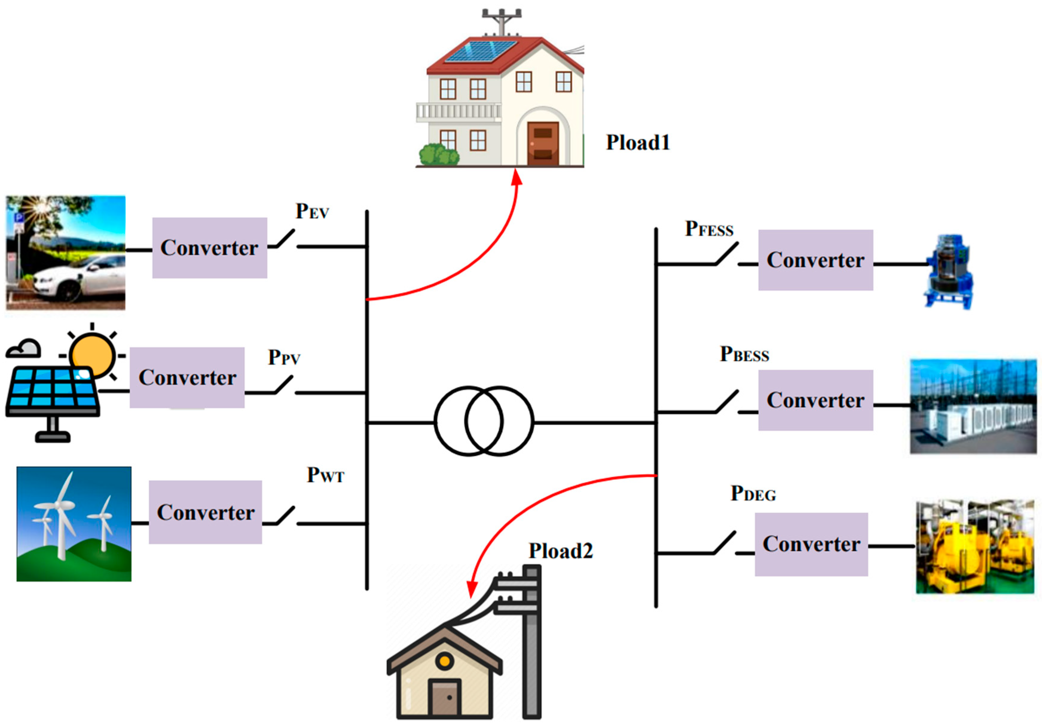
Control programs are usually more significant for MG systems running in island mode, also known as off-grid mode, than for those running in on-grid mode. An isolated AC-MG system is used as a case study in this instance. EVs, diesel generators (DGs), WTs, PV panels, battery energy storage systems (BESSs), and renewable energy sources (RESs) are all included in the isolated energy generation system (MG) shown in Figure 1. Power electronic interfaces connect DGs to MG, enabling synchronization in AC sources such as DEGs and WTs and voltage return in DC sources such as PV panels and energy storage devices. Every energy source has a component that can be used to disconnect from the MG network to heal itself or prevent the effects of severe disruptions [29].
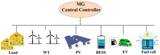
Figure 1.
The MG’s general structure with various energy production sources.
Control programs are usually more significant for MG systems running in island mode, also known as off-grid mode, than for those running in on-grid mode. An isolated AC-MG system is used as a case study in this instance. EVs, diesel generators (DGs), WTs, PV panels, battery energy storage systems (BESSs), and renewable energy sources (RESs) are all included in the isolated energy generation system (MG) shown in Figure 1. Power electronic interfaces connect DGs to MG, enabling synchronization in AC sources such as DEGs and WTs and voltage return in DC sources such as PV panels and energy storage devices. Every energy source has a component that can be used to disconnect from the MG network to heal itself or prevent the effects of severe disruptions [30].
MG Structure under Study
By utilizing this control technique, the energy storage sources in the feedback path can be controlled without the need for a separate controller. The proposed LFC structure, an islanded MG with DGs, EVs, WTs, PV panels, and diesel generators, energy storage units like BESSs and FESSs, and loads are displayed in Figure 2. The parameters of the MG under consideration are presented in Table 2. As a result, AC MG is connected to PV, BESS, and FESS devices via DC/AC interface inverters. Circuit breaker 1 connects all DGs and small-scale energy storage devices to the AC bus. A rotating reserve is supplied by the diesel power system for secondary frequency regulation.
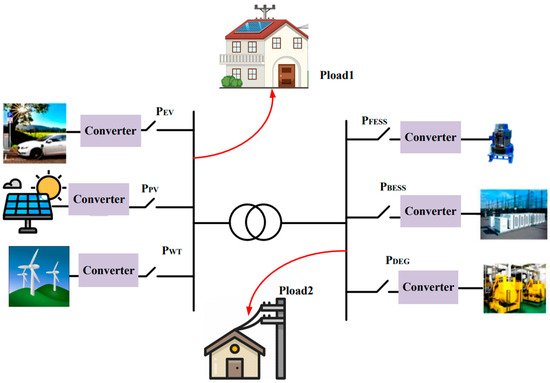
Figure 2.
General schematic of an MG system with different types of energy sources.
Table 2.
MMG system parameters.
3. The General Design of an MG with a Controller
3.1. The Basic Algorithm of HSA
HSA uses a random process. Hence, the need for any derived information, like other meta-heuristic optimization algorithms, is unnecessary to generate a new population of decision variables in search of a global optimum. Apart from this, the initial guess for the decision variable is not required for this algorithm. These inherent advantages make HSA a simple, faster, and easy to implement mathematical optimization algorithm. The basic HSA implementation steps are listed below.
Step 1: Set up the parameters of algorithm parameters for the identified optimization problem.
Step 2: Start harmony memory (HM) first.
Step 3: Get new coordination from HM.
Step 4: Update HM.
Step 5: Follow steps 3 and 4 again until the benchmark stops.
The subsequent five subsections provide additional examples of the aforementioned procedures.
- A.
- Step 1: Identification of optimization problem and algorithm parameters
Identifying the problem and declaring different parameters involved in an algorithm is the first step in any optimization method. In general, the optimization problem is defined as follows:
where:
is the cost function.
is a set of decision variables.
The decision variables’ lower and upper bounds are denoted by d and e, respectively. The HSA parameters that are needed to solve the optimization problem are also specified in this step. In the HSA algorithm, the random selection rule (RS), harmony memory selection rule (HMC), and adjustment rule (PA) are used to generate a new solution.
Step 2: HM initialization
This stage involves storing an HM matrix in a memory address designated as HM, which contains a collection of randomly generated solution vectors. Each row in the matrix corresponds to a distinct decision variable harmony vector, as follows:
Step 3: HM’s improvised new harmony
Improvisation is the process of creating a new coordination vector and is controlled by three principles: (a) harmony memory, (b) tuning, and (c) random selection.
A uniform random number, , is generated in the range [0,1] in the first phase. The memory determines the creation of the decision variable if is less than HMCR. If not, a random selection process (such as random reproduction between search boundaries) is used to generate . For every harmony vector j in j = [1, 2, …, d], is chosen and stored in the harmony memory. Furthermore, every choice variable , which is tuned with pitch adjusting rate (PAR) probability if the harmony memory updates it. The following is the tuning rule:
where:
is a uniform random number between [0,1].
FW determines the amount of movement or changes that may have occurred on the components of the new vector. The value of FW can be continuous or discrete based on the optimization problem itself. In general, PAR of the new harmony vector components is analogous to the behavior of musicians when they slightly change their tone frequencies to achieve better harmonies. More solutions are explored in the search space and the search results are improved.
Step 4: Update HM
If the newly created harmony vector is the worst of the worst harmony in the harmony vector (based on the value of the corresponding cost function) in HM, the worst harmony will be replaced by . However, other arrangements (in terms of least similarity) are considered for diversification in HM.
Step 5: Checking the stopping condition
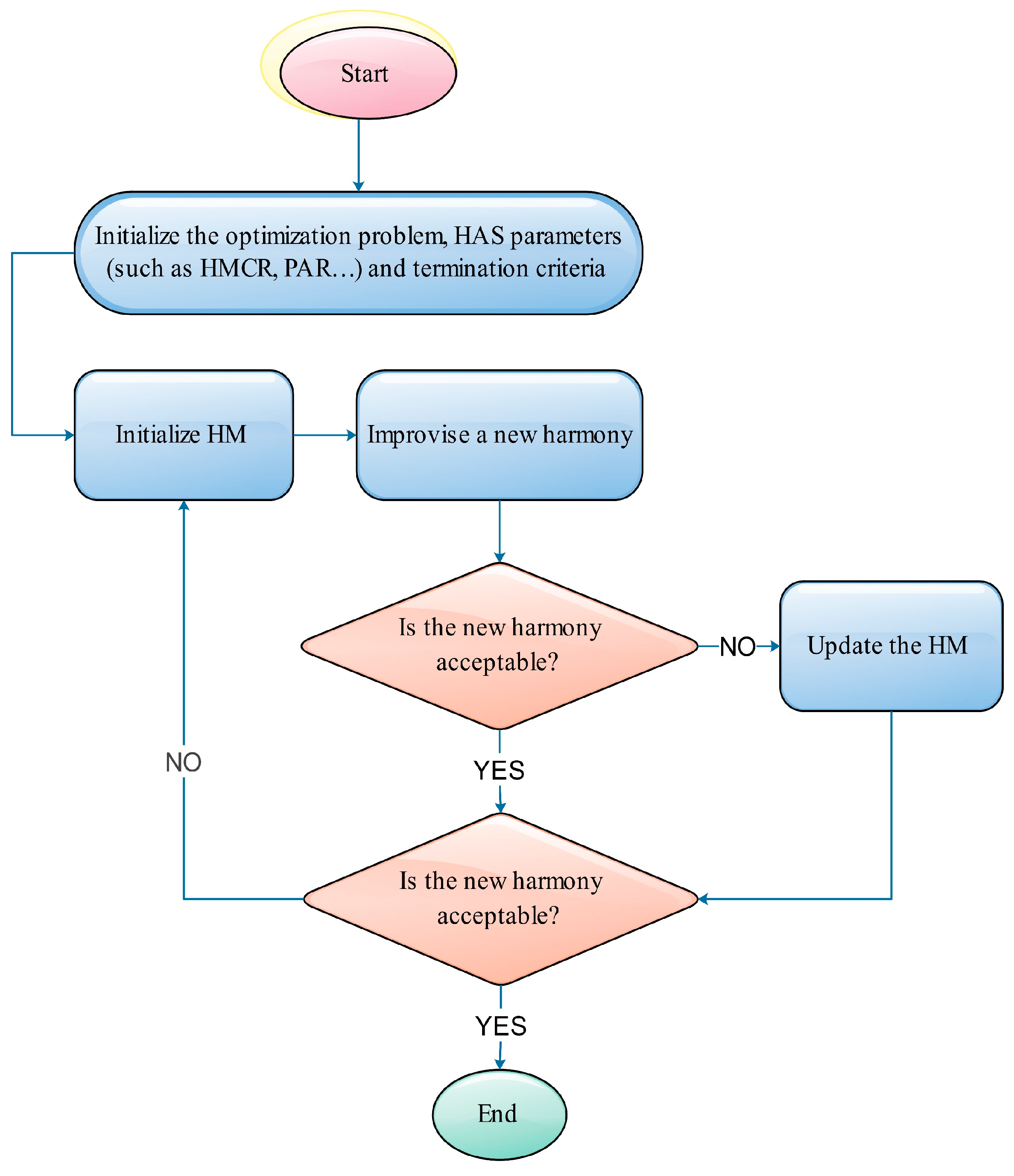
At this stage, in the stopping condition, for example, if the maximum number of MI iterations, is met, the execution of HSA is stopped. Otherwise, the third and fourth steps are repeated in search of new coordination. The flowchart of the HSA basic algorithm is shown in Figure 3.

Figure 3.
IHSA algorithm flowchart.
3.2. Improved Harmony Search Algorithm (IHSA)
The third stage introduces the HMCR and PAR parameters, which aid the algorithm in refining global and local solutions. They can support adjusting the algorithm’s convergence rate to the intended value and are essential parameters in the vectors’ accurate modification. Consequently, there is a lot of interest in precisely fixing these settings. The PAR and FW fixed values used by the classic HSA algorithm are established during the initialization stage (step 1) and are not modifiable during subsequent generations. The amount of iterations required for the algorithm to obtain the best answer is the primary issue with this approach [34].
Large FW values combined with small PAR values can make the algorithm inefficient and require a lot more iterations to find the best answer. In the beginning iterations, a more significant value should be used to execute the algorithm to improve the variety of the solution vectors, even though tiny values of FW in the final iterations increase the accuracy of solution vectors. Furthermore, when the method has become the optimal solution vector, large PAR values combined with lower FW values typically result in better final solutions.
where PAR(I) is the tuning rate at iteration I.
The minimum and maximum adjustment rates are denoted by and , respectively.
The minimum and maximum bandwidth are and , respectively.
3.3. Designing the ULM Controller Parameters Based on SIT2-FPID Using HAS
The MGCE from the matching MG is regarded as the input (, ) to the controller for the best design of the secondary controllers, and the controlled inputs (, ) can be defined for the system with ULM controller performance based on SIT-FPID. The objective function or cost function is chosen in the design of the optimal control system either (a) by taking into account the time response at many locations or (b) by taking into account the full-time response, which is chosen as the integral criterion (I). Integral absolute error (IAE), integral time absolute error (ITAE), integral squared error (ISE), and integral time squared error (ITSE) are examples of commonly used integral metrics. Although ISE has a longer settling time, it has less overshoot.
The performance index based on ITAE is taken into consideration for fine-tuning the suggested controllers in this article, which is motivated by the discussion above. Additionally, according to [35], the MMG’s targeted performance based on ITAE in the LFC region demonstrates an enhanced outcome.
As a result, the following is the definition of targeted performance according to ITAE criteria:
Given the constraints imposed by the controller parameters, the LFC design problem can be viewed as a restricted optimization problem. Consequently, the following definition of the restricted LFC issue applies:
Minimize ITAE
where and are the minimum and maximum ranges of the ULM feedback controller, respectively. and are respectively the minimum and maximum ranges of the SIT2-FPID compensator controller.
4. Simulation Results
This section describes the design and implementation of the model-free control system on top of the MMG system that was modeled in the previous Section 3. To check the effectiveness and practicality of the proposed method, several common scenarios in the field of MGs have been considered, which are as follows:
The first case is against step changes in load demand and non-renewable resources.
The second case is against random fluctuations in load demand and non-renewable resources.
The third case is the effect of changing the FOU coefficient on the control performance of the system.
The fourth case is against changes in system parameters.
The proposed control method has been compared with some standard methods such as SIT2-FPID and PID controllers to prove the superiority of the proposed model-free method. In order to provide a fair comparison method, the parameters of all controllers are optimized by the HSA algorithm. The simulation time for running the evolutionary process is considered to be equal to 75, and the changes in load and energy sources are applied to this system during this simulation time. The MMG system is implemented in the MATLAB/Simulink environment, while the codes related to the evolutionary algorithm program for designing the controller parameters are written (m.file). In the evolutionary process, the optimization algorithm has been repeated more than 20 times, and the best values obtained have been considered for the used controllers.
- A.
- The first scenario
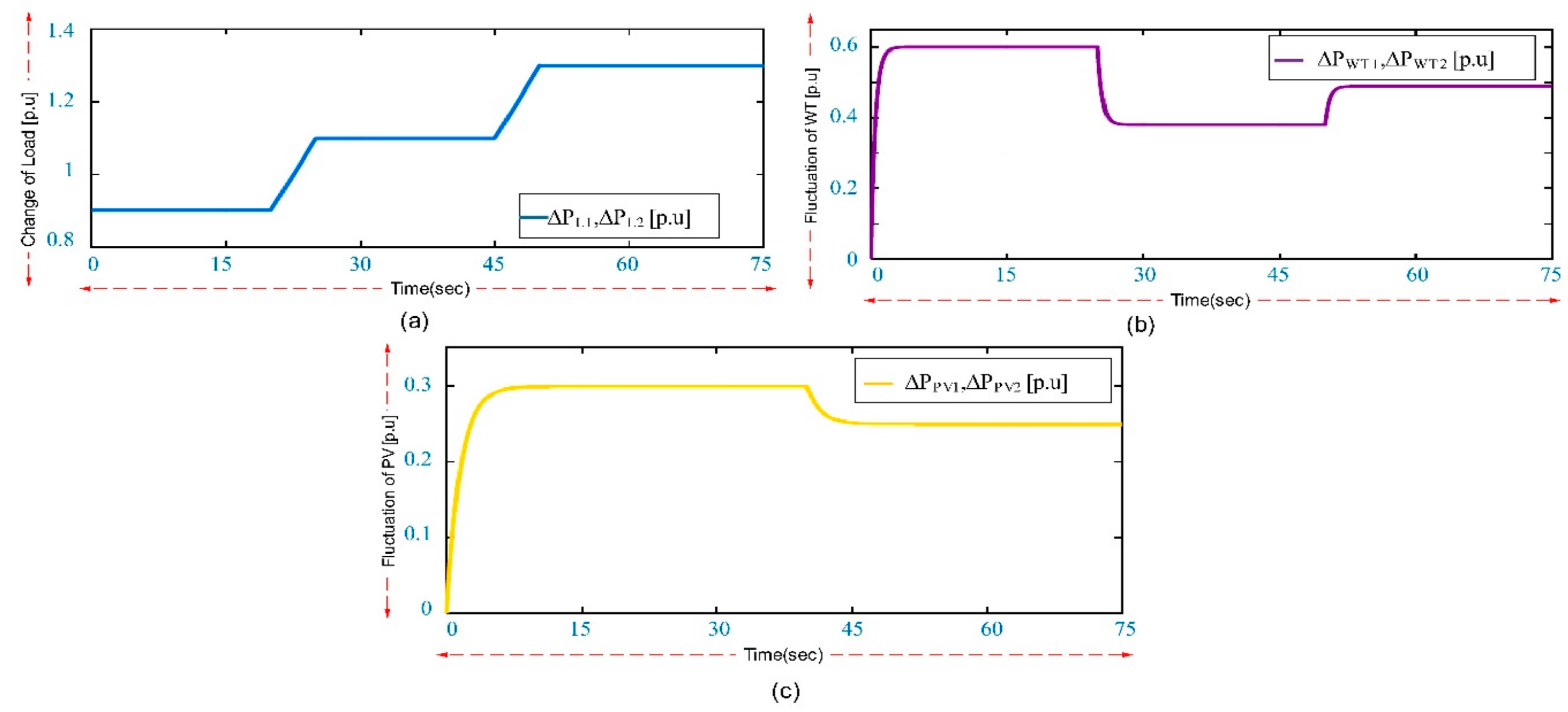
The controller performance in this scenario is assessed against changes in wind and solar energy and unexpected load variations without the use of the suggested model. The network is assumed to be in a steady state at the start of the simulation in this study. Step charts related to loading demand (), wind turbine output power (), and solar energy () are given in Figure 4.
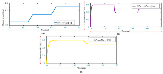
Figure 4.
Load profile and energy resources related to the first scenario: (a) load changes; (b) WT fluctuations; and (c) PV fluctuations.
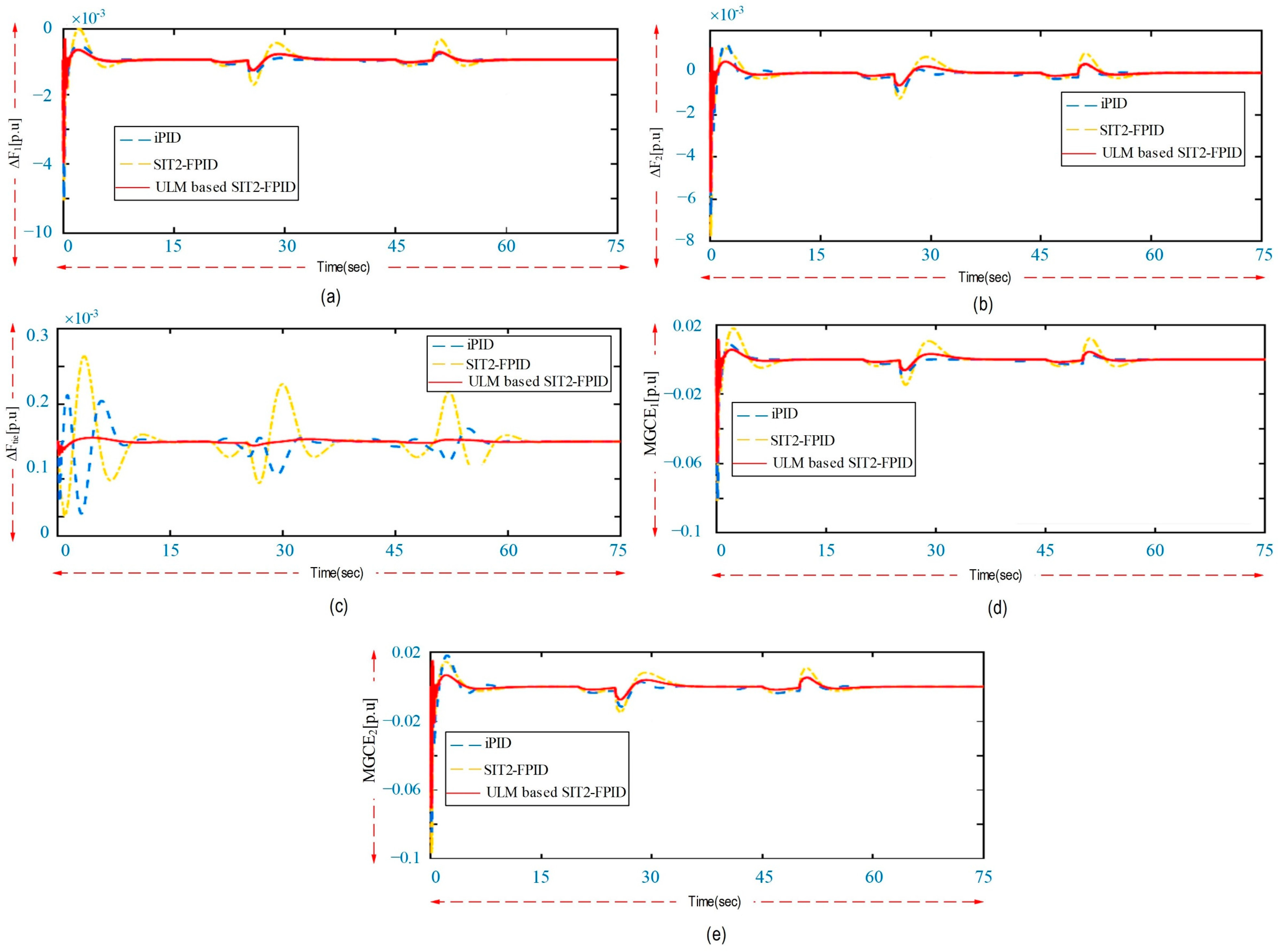
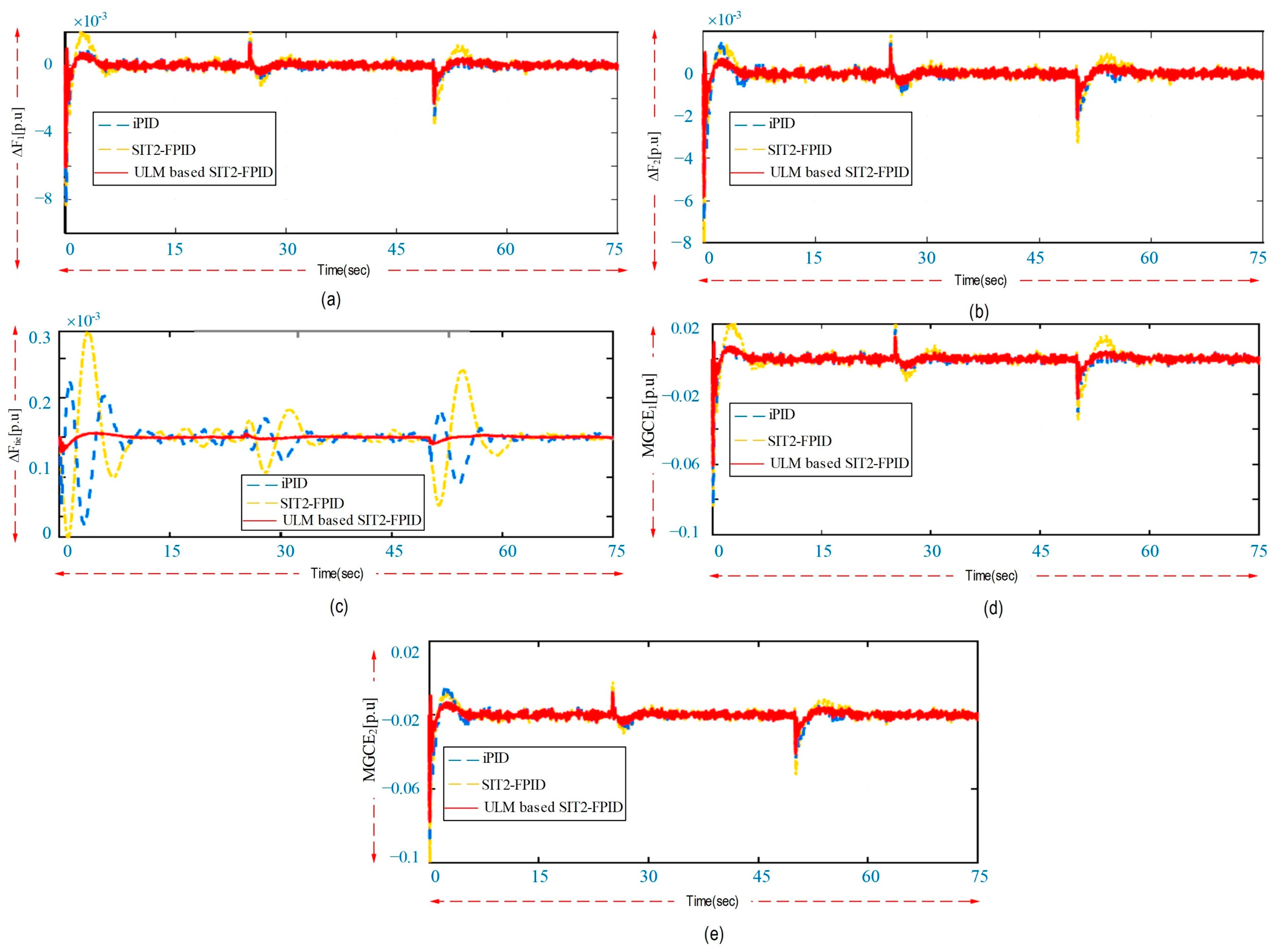
The dynamic transition outputs related to MGs, which include load frequency, MG control error, and MG communication power, are shown in Figure 5 for ULM-based SIT2-FPID, SIT2-FPID, and iPID controllers. The simulation results reveal that the proposed controller (implemented based on ULM-based SIT2-FPID) has better performance in reducing the fluctuations of system responses, especially in terms of system dynamics features such as settling time and maximum peak overshoot.
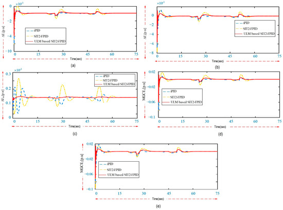
Figure 5.
Based on the first scenario, the dynamic reactions of the system: (a) frequency changes in 1MG; (b) frequency changes in 2MG; (c) load line power changes; (d) MG control error changes in 1MG; and (e) MG control error changes in 2MG.
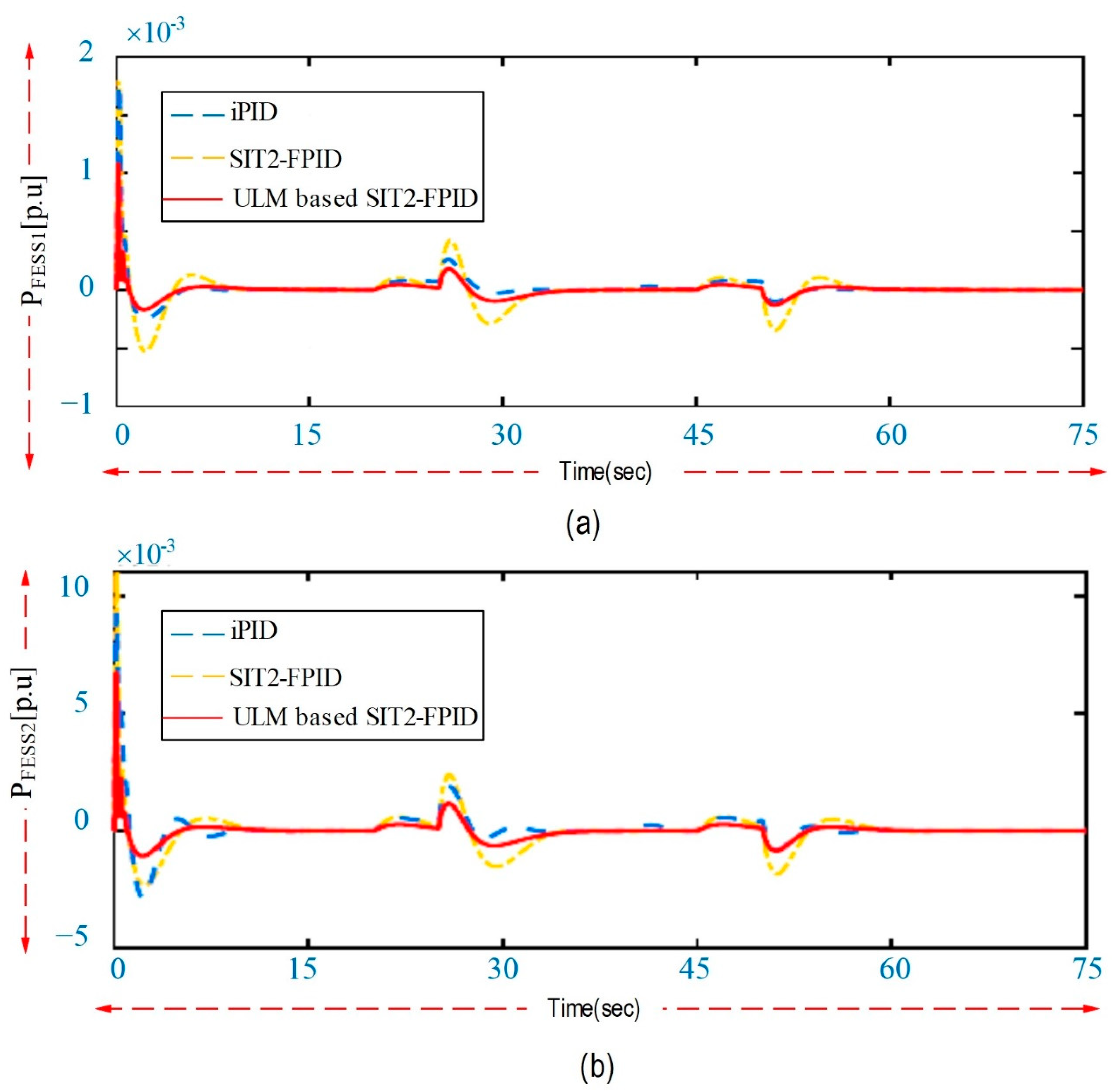
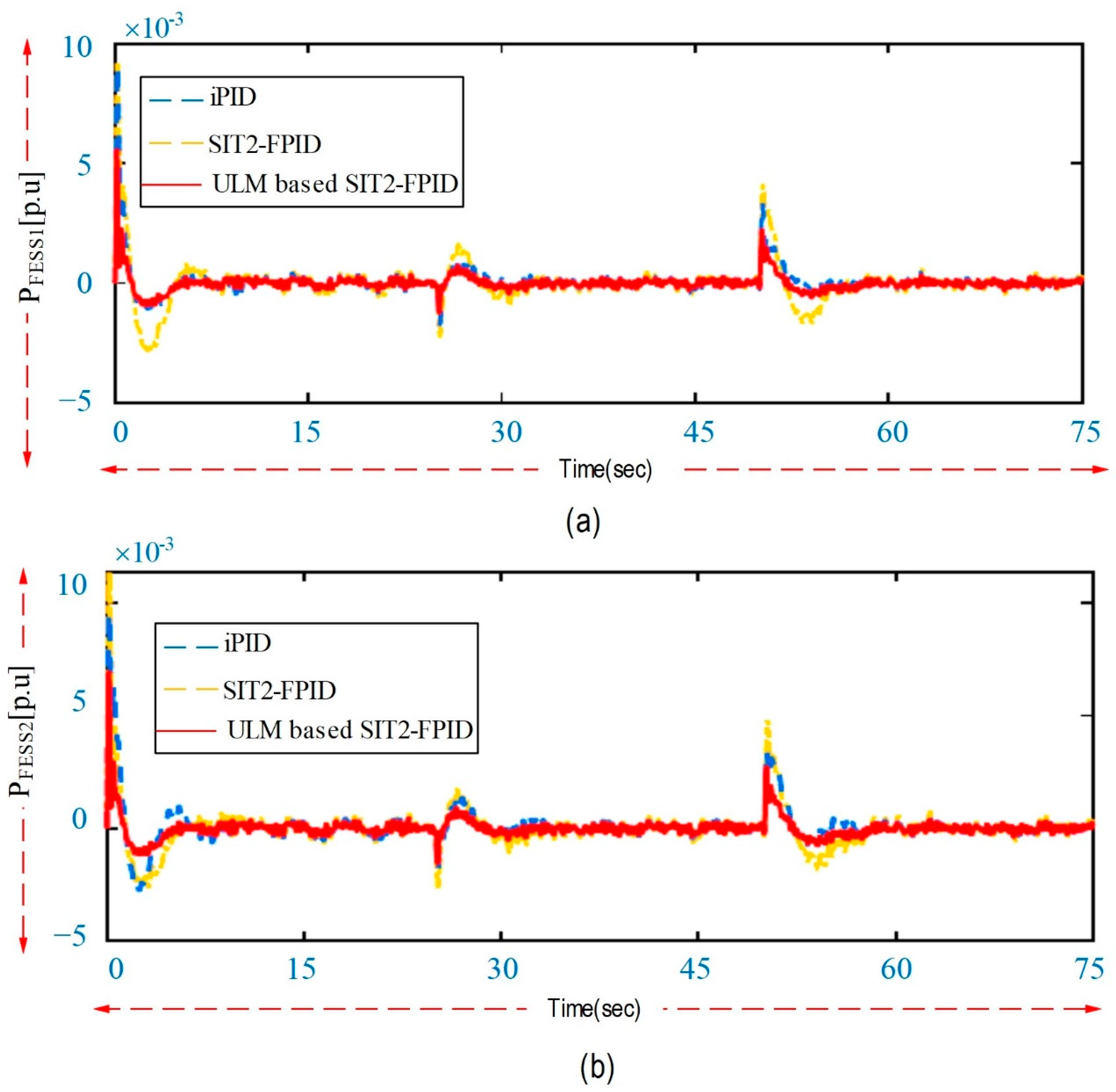
Also, the results related to the energy storage systems equipped in the feedback path from both MGs have been compared. The power produced by FESSs and BESSs for all designed controllers is shown in Figure 6. It is clear from the graphs in Figure 6 that, by using the ULM-based SIT2-FPID controller, the system reduces the fluctuations related to system responses faster than the SIT2-FPID and controllers. Therefore, the proposed method needs a smaller energy storage resource size. Also, this method reduces the amount of charging and discharging of batteries. This is a valuable result for MG systems regarding equipment health and cost-effectiveness.
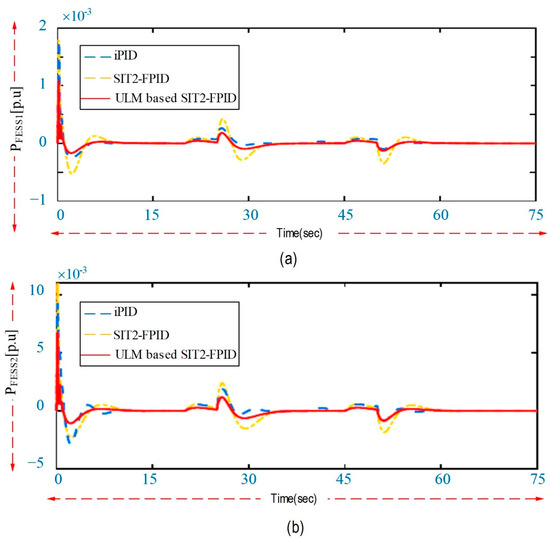
Figure 6.
Output responses of battery systems according to the first scenario: (a) FEES changes in 1MG; and (b) BEES changes in 2MG.
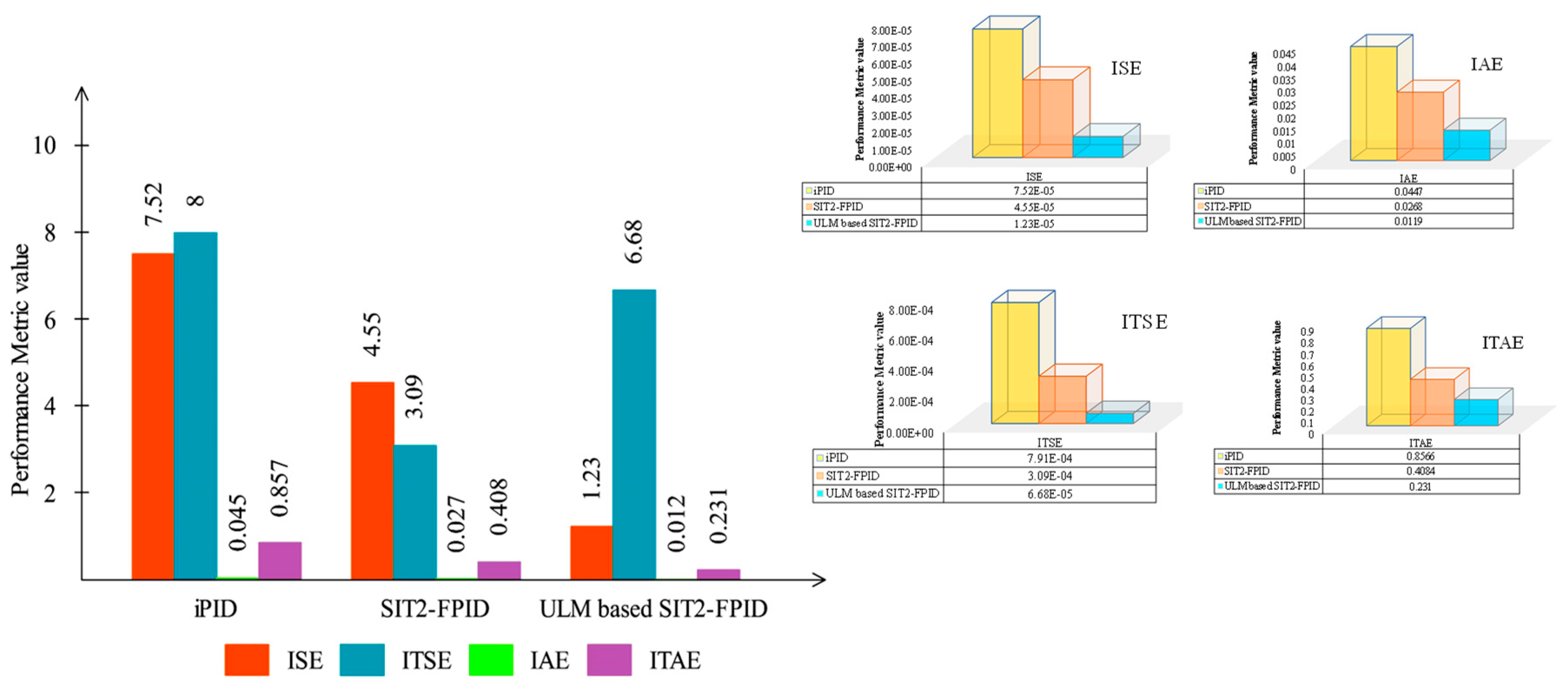
To perform a quantitative analysis, the performance of the controllers designed for the above system was checked by different efficiency criteria in the field of load frequency control. For this purpose, four types of efficiency criteria, including IAE, ITSE, ISE, and ITAE, have been considered, which are defined as follows:
Based on the definitions related to the above efficiency criteria, the system with an efficiency value closer to zero would perform better. The calculated results for the above efficiency criteria (Equations (13)–(16)) related to the controllers designed for MMG under the first scenario are shown in Figure 7. By carefully observing the bar graphs in Figure 8, it is shown that the ULM-based SIT2-FPI controller has the lowest value compared with other methods in all cases of efficiency criteria. Table 3 and Figure 8 show the improvement rate of the proposed method compared to other controllers. The improvement rates compared to the STI-FPID controller are 73.3819 for ISE, 73.0681 for ITSE, 55.597 for IAE, and 43.4378 for ITAE. Also, compared with iPID, the improvement percentages are 83.7048 for ISE, 91.555 for ITSE, 73.3781 for IAE, and 73.0329 for ITAE.
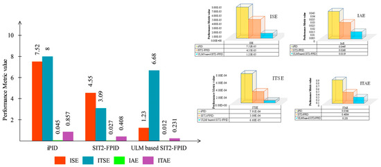
Figure 7.
Comparison of efficiency indicators of controllers designed according to the first scenario.
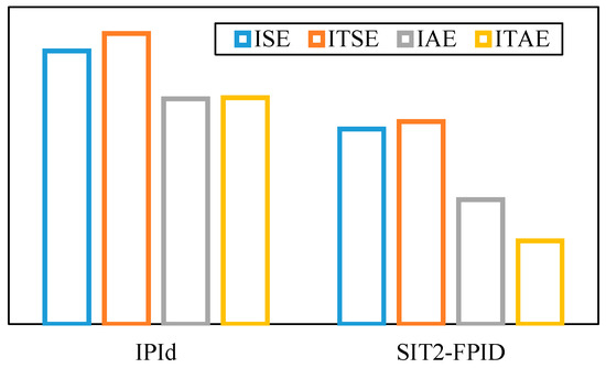
Figure 8.
The proposed ULM-based SIT2-FPID controller’s improvement percentage concerning the iPID and SIT2-FPID controllers in the first scenario.
Table 3.
The improvement percentage of the proposed model-free method compared to the SIT2-FPID and controllers for the efficiency criteria of IAE, ITSE, ISE, and ITAE in the first scenario.
- B.
- The second scenario
At this stage, the ULM-based SIT2-FPI controller effectiveness is studied under small fluctuation changes in load demand and non-renewable resources for the MMG system. In this scenario, power generation fluctuations have been considered using Equation (17), which is generally used in MG systems.
In the above equation, and are the random power coefficient and average value, respectively. is the normalizing constant of the generated power (). switches the power level of fluctuations to a defined value in time. The details of the random model parameters for load demand and non-renewable energy sources are given in Table 4. In Table 5, the term is a uniform random function between −1 and +1.
Table 4.
Parameters of the random model of load demand and renewable energy sources.
Table 5.
The improvement percentage of the proposed model-free method compared to the SIT2-FPID and iPID controllers for the efficiency criteria of IAE, ITSE, ISE and ITAE in the second scenario.
The graph related to arbitrary powers , , and obtained in Table 3 is shown in Figure 9. The system dynamic responses under the profile fluctuations in terms of load frequency, MG control error, and MG communication power are shown in Figure 9. According to Figure 10, despite random load demand fluctuations and non-renewable energy sources, the ULM-based SIT2-FPI controller provides acceptable performance in terms of MG stability. It can also be seen that the responses related to the ULM-based SIT2-FPI controller have a smaller range of fluctuations than other controllers and reach a steady state faster.
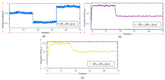
Figure 9.
Load profile and energy resources related to the second scenario: (a) load changes; (b) PV fluctuations; and (c) WT fluctuations.
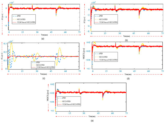
Figure 10.
System dynamic responses according to the second scenario: (a) frequency changes in 1MG; (b) frequency changes in 2MG; (c) load line power changes; (d) MG control error changes in 1MG; and (e) MG control error changes in 2MG.
The energy storage resources for fluctuating amounts of load and non-renewable energy sources are shown in Figure 11. Similarly to the previous case, using the controller without the proposed model improves the energy storage performance. At the same time, it performs better than the comparative controllers.
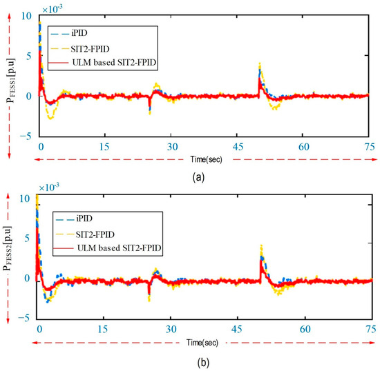
Figure 11.
Output responses of battery systems according to the second scenario: (a) FEES changes in 1MG; and (b) FEES changes in 2MG.
The efficiency index related to each controller designed for load fluctuations and non-renewable energy production sources is given in Figure 12. Also, the values related to the percentage of improvement are given in Table 3 and Figure 13. It is evident that the controller can achieve higher ITSE, ISE, IAE, and ITAE values without the suggested model, indicating an improvement in the system’s overall dynamic performance.
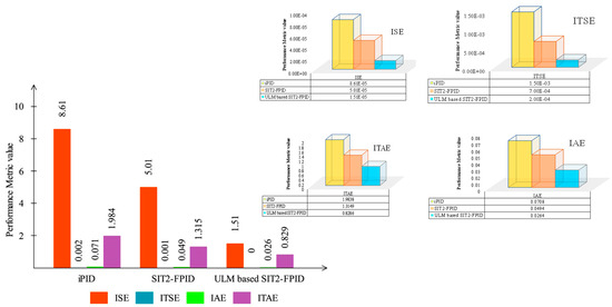
Figure 12.
Comparison of efficiency indicators of controllers designed according to the second scenario.
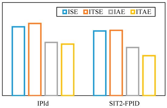
Figure 13.
The improvement percentage of the proposed ULM-based SIT2-FPID controller compared to the iPID controller and the SIT2-FPID controller according to the second scenario.
Notably, the comparison of dynamic responses and statistical analyzes related to the first and the second scenario reveals that the performance of the MG system has decreased under random fluctuations of load and energy sources compared to step changes. Therefore, it causes more challenges in terms of stability when random fluctuations are applied to the system. Under such conditions, classical controllers such as are incapable of compensating for the system’s dynamic responses under such fluctuating disturbances.
- C.
- The third scenario
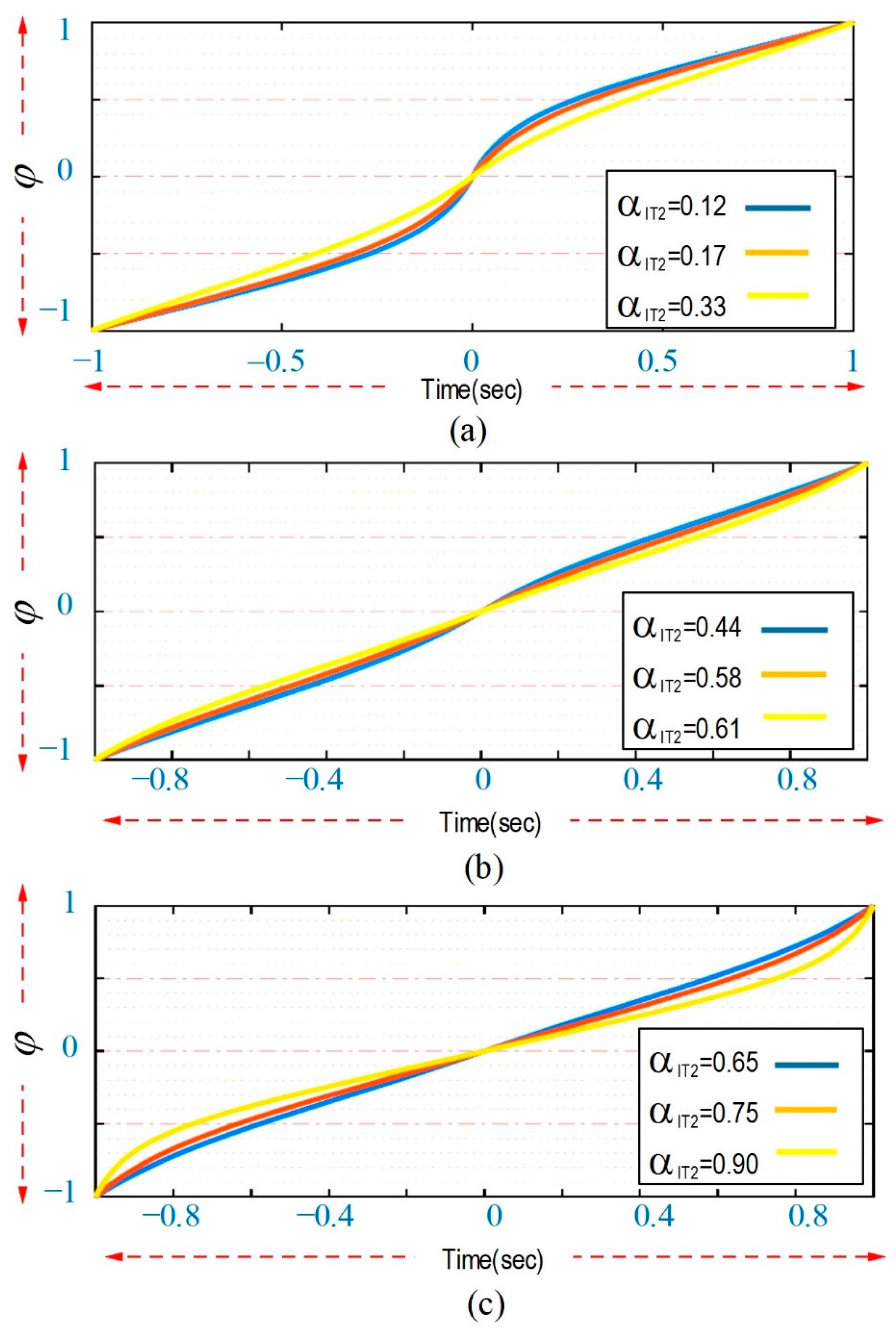
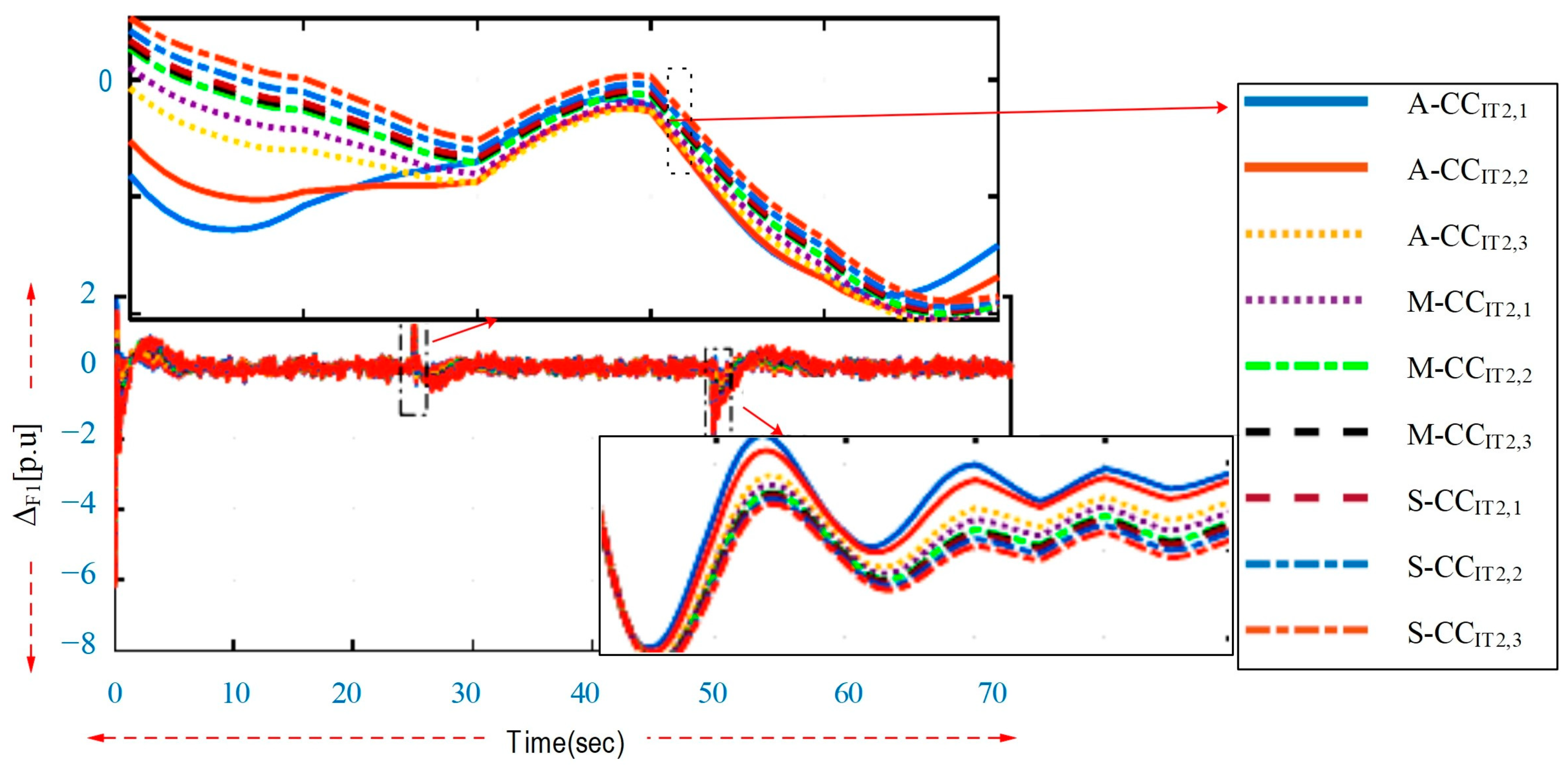
In this scenario, by changing the αIT2 parameter that forms the FOU forms, different types of CSs are produced, and their effect on the control performance of the proposed ULM-based on SIT2-FPID is investigated. For this purpose, different types of αIT2 coefficients for possible M-CC, A-CC, and S-CC modes have been considered in Table 6. Figure 14 shows the different SIT2-FLC curves obtained from Table 7.
Table 6.
αIT2 coefficient values produce possible M-CC, A-CC, and S-CC modes.
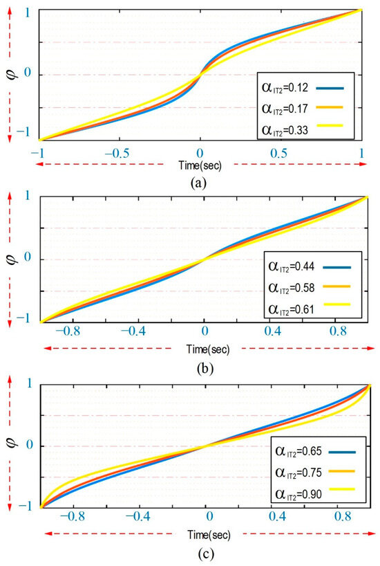
Figure 14.
SIT2-FLC level control curve based on αIT2 changes: (a) A-CC; (b) M-CC; and (c) S-CC.
Table 7.
Uncertain parameters of the MMG system.
In Figure 14, A-CC has a comparatively higher input sensitivity than S-CC when σ is around 1. Its sensitivity is low when the input signal is near 1, but S-CC’s sensitivity is strong in the vicinity of 1. Lastly, M-CC is an amalgam of A-CC and S-CC. As a result, the sensitivity of the error signal decreases when it approaches ± 1 and increases when it approaches 1.
The dynamic responses by the MMG system for the first area for different mappings presented in Figure 14 are given in Figure 15. By changing the parameter , the system’s performance changes. Therefore, by changing the adjustable parameter , it is possible to achieve desired control characteristics such as robustness, response smoothness, short settling time, and low overshoot.
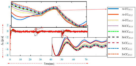
Figure 15.
Frequency response changes for 1MG under different types of M-CC and A-CC.
- D.
- The fourth scenario
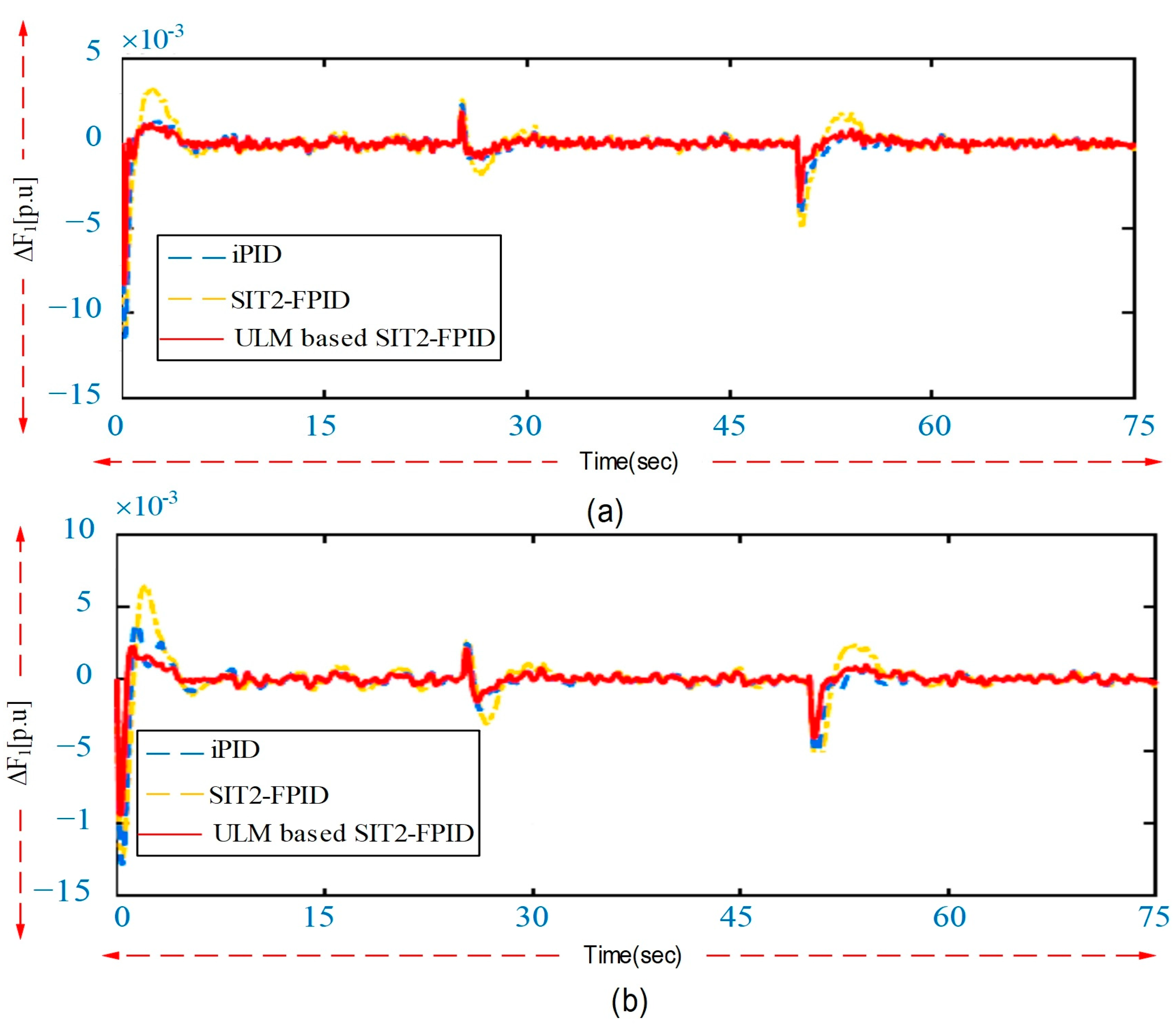
To test the resistance of the controller to parameter changes, some system parameters related to the second scenario have been changed. For this purpose, two types of uncertain conditions have been considered for the system (given in Table 7). According to Table 7, the percentage of uncertain changes in the second condition is higher than the uncertain changes in the first condition, which imposes more severe instability on the system. Figure 16a,b show the results of the dynamic responses related to the frequency changes of the first MG under the first and second conditions. As can be seen, the proposed controller performs better under parameter uncertainties. Therefore, it can be concluded that the super system is less sensitive to uncertainty than other methods and provides a higher resistance level. It is also clear from Figure 16 that, as predicted under the second condition, the system level experiences more fluctuations than under the first condition.
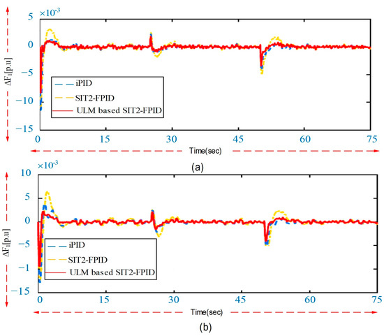
Figure 16.
Frequency response changes of MG under: (a) the first conditions; and (b) the second conditions.
5. Conclusions
This article investigates a hybrid power system with different energy sources, including BESSs, WTs, PV panels, DEGs, FESSs, and EVs, as the studied system under MG form. This research assumes that the system under study works in island mode to check its control conditions under conditions independent from the network. Simulations related to step and fluctuating disturbances (the first and second scenarios) showed that the ULM controller method based on SIT2-FPID with ESO observer successfully reduced frequency fluctuations, line power fluctuations, and MG controller error. In addition, the proposed method performed better than ULM and SIT2-FPID methods in overshoot terms, settling time, steady state error against the step, and fluctuating disturbances of energy sources and load changes. Statistical analysis was performed to better examine the designed controllers. For this purpose, the performance of the designed controllers under several efficiency criteria, including ISE, IAE, ITSE, and ITAE, was compared. Statistical analysis showed that the proposed ULM controller based on SIT2-FPID obtained the lowest value for all the above indexes. Since and responses are considered in these indexes, the superiority of the proposed method under the above efficiency criteria showed the improvement of the dynamic performance of the system in comparison with the ULM and SIT2-FPID methods. Also, in the first and second scenarios, it was observed that by using the proposed controller, BESS and FESS batteries experienced a lower level of fluctuations compared to ULM and SIT2-FPID methods, which reduced the charge and discharge changes of the batteries and thus increased the battery lifetime. This also indicated that when the proposed method was used in the MMG system, the size of the batteries could be smaller, improving the energy efficiency of the whole system.
To check the robustness of the controller, a high level of parameter uncertainty was applied in two different tests, including the fourth scenario, in the MMG system under study. For this purpose, some basic system parameters, including , , M, , , , and , were changed under a wide range of system working conditions. The robustness analysis of the fourth scenario showed that when the parameters of the MMG changed drastically, the proposed method could still maintain the system’s stability.
Author Contributions
Conceptualization, M.A.; methodology, M.A.; software, L.T.; validation, M.A., L.T., and M.A.N.; investigation, writing—original draft preparation, M.A.; writing—review and editing, L.T. and M.A.N.; visualization, M.A.N.; supervision, L.T. and M.A.N. All authors have read and agreed to the published version of the manuscript.
Funding
This research received no external funding.
Data Availability Statement
The original contributions presented in the study are included in the article, further inquiries can be directed to the corresponding authors.
Conflicts of Interest
The authors declare no conflicts of interest.
Abbreviations
| MG | Micro-grid | T&D | Transmission and distribution |
| BESS | Battery energy storage system | LV | Low voltage |
| EVs | Electric vehicles | KP | Kyoto Protocol |
| ULM | Ultra-local model | MPC | Model predictive control |
| ESO | Extended state observer | ITSE | Integral time square error |
| LFC | Load frequency control | PSO | Particle swarm optimization |
| MMG | Multi-microgrid | V2G | Vehicle-to-grid |
| FLC | Fuzzy logic controller | PHEV | Plug-in hybrid electric vehicle |
| SIT2 | Single input interval type-2 | ULM | Ultra-local model |
| IHSA | Improved Harmon search algorithm | FSs | Fuzzy sets |
| CHP | Combined heat and power | FOU | Footprint of uncertainty |
| DG | Distributed generation | ECS | Energy capacitor systems |
| DER | Distributed energy resources | WT | Wind generator |
| RESs | Renewable energy sources | SISO | Single Input–Single Output |
| WP | Wind power | ESO | Extended state observer |
| WTG | Wind turbine generator | FM | Fuzzy mapping |
| DEG | Diesel engine generator | MFs | Membership functions |
| PV | Photovoltaic panel | CC | Control curve |
| FESS | Flywheel energy storage system | LP | Linear programming |
| BESS | Battery energy storage system | NLP | Non-linear programming |
| ITAE | Integral time absolute error | ITSE | Integral time square error |
| MI | Maximum iteration | IAE | Integral absolute error |
References
- Irmak, E.; Kabalcı, E.; Calpbinici, A. Event-triggered distributed secondary control for enhancing efficiency, reliability and communication in island mode DC microgrids. IET Renew. Power Gener. 2024, 18, 78–94. [Google Scholar] [CrossRef]
- Khalil, A.E.; Boghdady, T.A.; Alham, M.H.; Ibrahim, D.K. A novel cascade-loop controller for load frequency control of isolated microgrid via dandelion optimizer. ASEJ. 2024, 15, 102526. [Google Scholar]
- Mohammad, Z.; Nasab, A.; Padmanaban, M.; Khoobani, S. Big data for SMART Sensor and Intelligent Electronic devices–Building application. In Smart Buildings Digitalization; CRC Press: Boca Raton, FL, USA, 2022; pp. 11–28. [Google Scholar]
- Hu, S.; Ge, X.; Chen, X.; Yue, D. Resilient Load Frequency Control of Islanded AC Microgrids Under Concurrent False Data Injection and Denial-of-Service Attacks. IEEE Trans. Smart Grid. 2022, 14, 690–700. [Google Scholar] [CrossRef]
- Anuoluwapo, A.; Musumpuka, R.; Dorrell, D. Cyberattack-Resilient Secondary Frequency Control Scheme for Stand-Alone Microgrids. IEEE Trans. Ind. Electron. 2022, 70, 1622–1634. [Google Scholar]
- Shi, K.; Cai, X.; She, K.; Zhong, S.; Soh, Y.; Kwon, O. Quantized memory proportional–integral control of active power sharing and frequency regulation in island microgrid under abnormal cyber attacks. Appl. Energy 2022, 322, 119540. [Google Scholar] [CrossRef]
- Milad, S.; Azizi, S. Decentralized Robust Control of a Coupled Wind Turbine and Diesel Engine Generator System. IEEE Trans. Power Syst. 2022, 38, 807–817. [Google Scholar]
- Nasab, A.; Abedinzadeh, M.; Padmanaban, M.H.; Pandav, S.; Zand, K. Robust Torque Control for Induction Motor Drives Using Fuzzy and PID Control. In Proceedings of the 2023 33rd Australasian Universities Power Engineering Conference (AUPEC), Ballarat, Australia, 25–27 September 2023. [Google Scholar]
- Ahmed, M.; Magdy, G.; Khamies, M.; Kamel, S. An efficient coordinated strategy for frequency stability in hybrid power systems with renewables considering interline power flow controller and redox flow battery. J. Energy Storage 2022, 52, 104835. [Google Scholar] [CrossRef]
- Al-Shibli, W.K.; Ehsan-maleki, B. Charging management of electric vehicles with the presence of renewable resources. Renew. Energy Focus 2024, 48, 100536. [Google Scholar]
- Mahmood, M.; Taghizadeh, M. Uncertainty estimator-based dual layer adaptive fault-tolerant control for wind turbines. Renew. Energy 2022, 188, 545–560. [Google Scholar]
- Maroti, P.K.; Muyeen, S.M. Sensitivity analysis index to determine the optimal location of multi-objective UPFC for improvement of power quality parameters. Energy Rep. 2023, 10, 431–438. [Google Scholar]
- Dashtaki, A.A.; Blaabjerg, F. Uncertainty compensation with coordinated control of EVs and DER systems in smart grids. Sol. Energy 2023, 263, 111920. [Google Scholar]
- Pournazarian, B.; Sangrody, R.; Lehtonen, M.; Gharehpetian, G.B.; Pouresmaeil, E. Simultaneous Optimization of Virtual Synchronous Generators Parameters and Virtual Impedances in Islanded Microgrids. IEEE Trans. Smart Grid 2022, 13, 4202–4217. [Google Scholar] [CrossRef]
- Dashtdar, M.; Flah, A.; El-Bayeh, C.Z.; Tostado-Véliz, M.; Al Durra, A.; Aleem, S.H.E.A.; Ali, Z.M. Frequency control of the islanded microgrid based on optimized model predictive control by PSO. IET Renew. Power Gener. 2022, 16, 2088–2100. [Google Scholar] [CrossRef]
- Hayoun, M.; Mohammadreza, F.; Sadra, R.M.; Shokoufeh, B.; Ankit, S.; Myounghoon, J. The influence of olfactory and visual stimuli on students’ performance and mood in virtual reality environment. In Proceedings of the Human Factors and Ergonomics Society Annual Meeting; SAGE Publications: Los Angeles, CA, USA, 2023; Volume 67. [Google Scholar]
- Adwait, D.; Chayanjit, G.; Mohit, U.K.; Aishwaryadev, B.; Erfan, P.; Rabiul, H.M.; Amirali, N.; Golam, D.M.; Hanseup, K.; Carlos, H.M. Automatic Light Intensity Modulation Using TNC-Based Artificial Iris for Smart Contact Lens. In Proceedings of the 2023 IEEE Sensors, Vienna, Austria, 28 November 2023. [Google Scholar]
- Ding, X.; Lin, W.; Xu, J.; Sun, Y.; Yao, L.; Mao, B. Coordinated frequency control for isolated power systems with high penetration of DFIG-based wind power. CSEE J. Power Energy Syst. 2022, 1–15. [Google Scholar] [CrossRef]
- Hasankhani, A.; Tang, Y.; VanZwieten, J.; Sultan, C. Spatiotemporal Optimization for Vertical Path Planning of an Ocean Current Turbine. IEEE Trans. Control Syst. Technol. 2022, 31, 587–601. [Google Scholar] [CrossRef]
- Padmanaban, S. Electric vehicle charger energy management by considering several sources and equalizing battery charging. Renew. Energy Focus 2024, 50, 100592. [Google Scholar]
- Gao, S.; Dai, R.; Cao, W.; Che, Y. Combined Provision of Economic Dispatch and Frequency Regulation by Aggregated EVs Considering Electricity Market Interaction. IEEE Trans. Transp. Electrif. 2022, 9, 1723–1735. [Google Scholar] [CrossRef]
- Jaewan, S.; Song, S.; Jang, G. Power imbalance-based droop control for vehicle to grid in primary frequency regulation. IET Generat. Transmiss. Distrib. 2022, 16, 3374–3383. [Google Scholar]
- Hannan, M.A. Vehicle to grid-connected technologies and charging strategies: Operation, control, issues and recommendations. J. Clean. Prod. 2022, 339, 130587. [Google Scholar] [CrossRef]
- Vásquez Quintero, A.; Pérez-Merino, P.; De Smet, H. Artificial Iris on Smart Contact Lens using Twisted Nematic Cell for Photophobia Alleviation. In Proceedings of the 2023 IEEE Photonics Conference (IPC), Rome, Italy, 10–14 November 2023. [Google Scholar]
- Zand, M.; Sanjeevikumar, P.; Maroti, P.K.; Holm-Nielsen, J.B. Energy management strategy for solid-state transformer-based solar charging station for electric vehicles in smart grids. IET Renew. Power Gener. 2020, 14, 3843–3852. [Google Scholar] [CrossRef]
- Nikoufard, M.; Hatami, M. Extremely compact slanted waveguide hybrid plasmonic polarization rotator. Opt. Commun. 2017, 382, 232–236. [Google Scholar] [CrossRef]
- Muttaqi, K.M.; Rahman, O.; Sutanto, D.; Lipu, M.S.H.; Abdolrasol, M.G.M.; Hannan, M.A. High-Frequency Ripple Injection Signals for the Effective Utilization of Residential EV Storage in Future Power Grids with Rooftop PV System. IEEE Trans. Ind. Appl. 2022, 58, 6655–6665. [Google Scholar] [CrossRef]
- Islam, S.; Iqbal, A.; Marzband, M.; Khan, I.; Al-Wahedi, A.M.A.B. State-of-the-art vehicle-to-everything mode of operation of electric vehicles and its future perspectives. Renew. Sustain. Energy Rev. 2022, 166, 112574. [Google Scholar] [CrossRef]
- Gheisarnejad, M.; Mirzavand, G.; Ardeshiri, R.R.; Andresen, B.; Khooban, M.H. Adaptive Speed Control of Electric Vehicles Based on Multi-Agent Fuzzy Q-Learning. IEEE Trans. Emerg. Topics Comput. Intell. 2022, 7, 102–110. [Google Scholar] [CrossRef]
- Dae-Sung, L.; Son, S.-Y. PV forecasting model development and impact assessment via imputation of missing PV power data. IEEE Access 2024, 12, 12843–12852. [Google Scholar]
- Oshnoei, A.; Kheradmandi, M.; Muyeen, S.M.; Hatziargyriou, N.D. Disturbance observer and tube-based model predictive controlled electric vehicles for frequency regulation of an isolated power grid. IEEE Trans. Smart Grid 2021, 12, 4351–4362. [Google Scholar] [CrossRef]
- Noruzi, S.; Ghoreishy, H.; Ahmad, A.A.; Tahami, F.; Ahmadiahangar, R.; Rosin, A. Variable frequency control method of boost converter operating in boundary conduction mode. In Proceedings of the 2020 IEEE 61th International Scientific Conference on Power and Electrical Engineering of Riga Technical University (RTUCON), Riga, Latvia, 7 November 2020. [Google Scholar]
- Norouzi, S.; Ghoreishy, H.; Ahmad, A.A.; Tahami, F. Stability analysis of variable frequency control method of soft switching for boost converter with wide bandgap semiconductors. In Proceedings of the 2023 14th Power Electronics, Drive Systems, and Technologies Conference (PEDSTC), Babol, Iran, 2 February 2023. [Google Scholar]
- Alizadeh, M.; Beheshti, M.T.H.; Ramezani, A.; Bolouki, S. An optimized hybrid methodology for short-term traffic forecasting in telecommunication networks. Trans. Emerg. Telecommun. Technol. 2023, 34, e4860. [Google Scholar] [CrossRef]
- Özdemir, M.T.; Öztürk, D. Comparative performance analysis of optimal PID parameters tuning based on the optics inspired optimization methods for automatic generation control. Energies 2017, 10, 2134. [Google Scholar] [CrossRef]


Disclaimer/Publisher’s Note: The statements, opinions and data contained in all publications are solely those of the individual author(s) and contributor(s) and not of MDPI and/or the editor(s). MDPI and/or the editor(s) disclaim responsibility for any injury to people or property resulting from any ideas, methods, instructions or products referred to in the content. |
© 2024 by the authors. Licensee MDPI, Basel, Switzerland. This article is an open access article distributed under the terms and conditions of the Creative Commons Attribution (CC BY) license (https://creativecommons.org/licenses/by/4.0/).