
Conceptual Design of an Unmanned Electrical Amphibious Vehicle for Ocean and Land Surveillance

 , , and
Abstract
1. Introduction
1.1. Related Works
1.2. Motivation and Main Objective
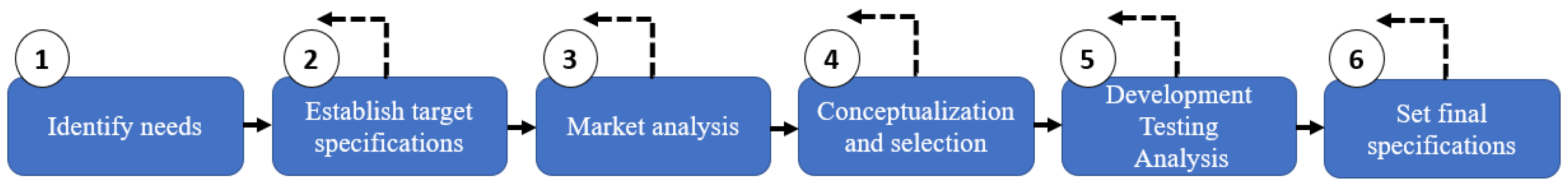
2. Materials and Methods
2.1. Identification of the Needs
2.2. Target Specifications
2.3. Market Research
2.4. Conceptualization and Development
2.4.1. Land Propulsion
2.4.2. Hydrostatic and Intact Stability Analyses
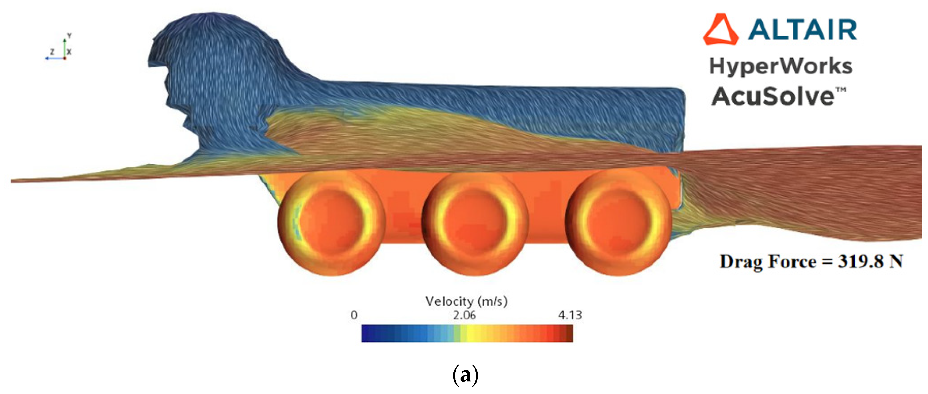
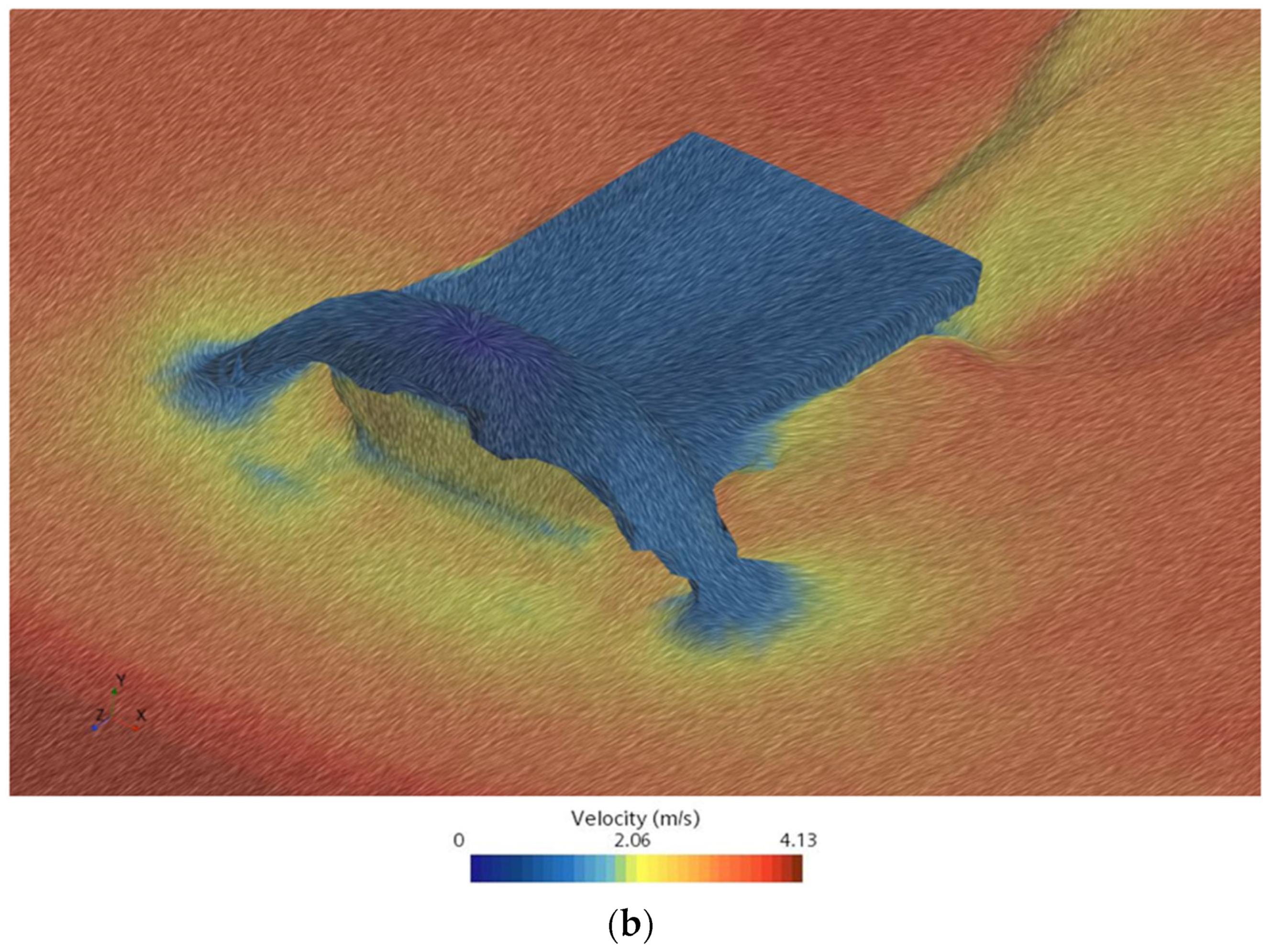
2.4.3. Water Propulsion
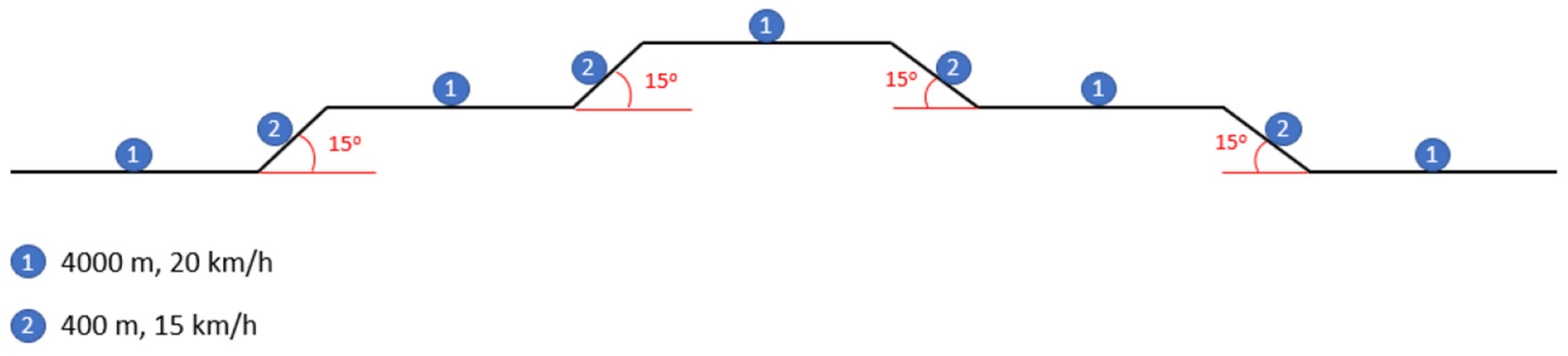
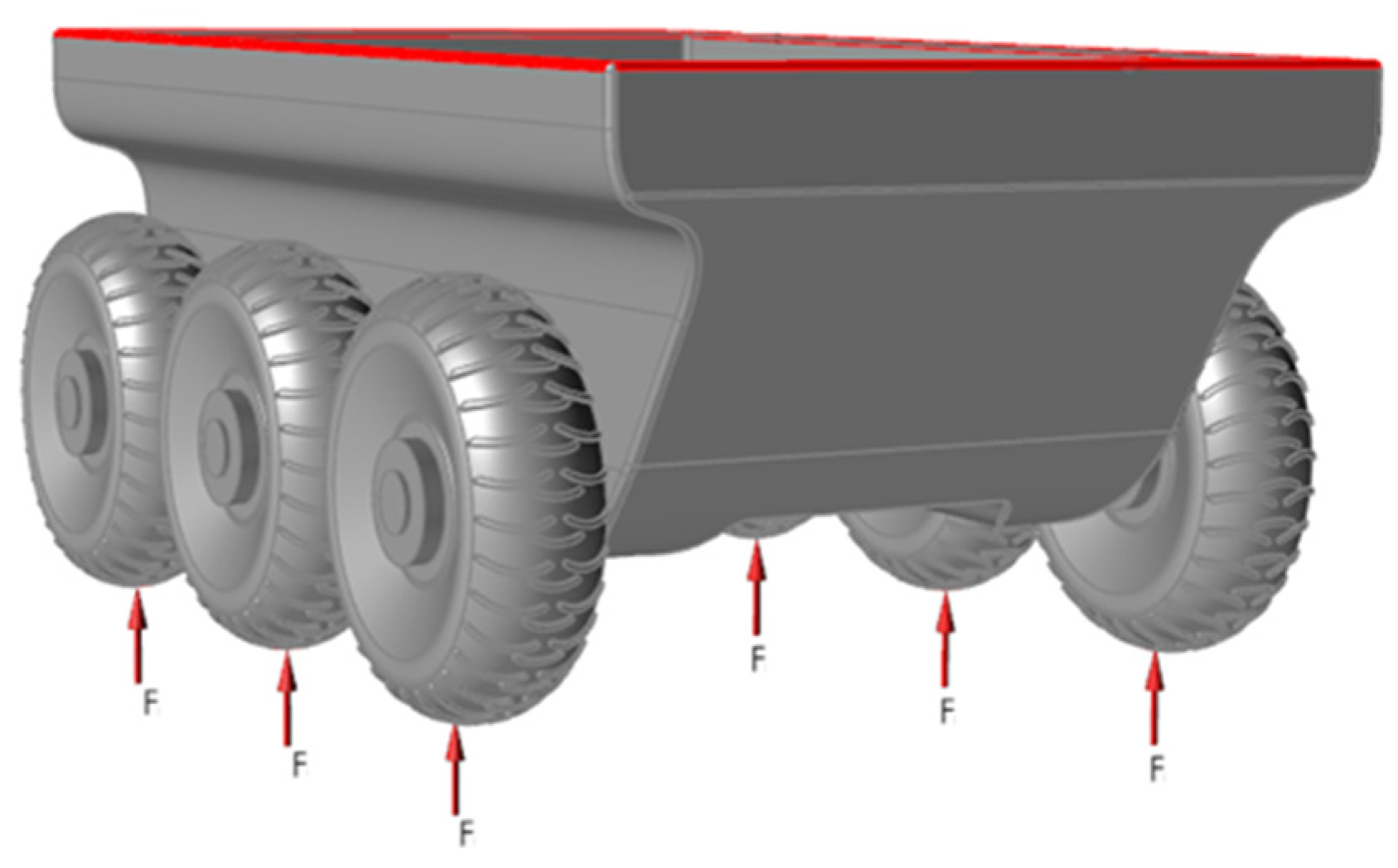
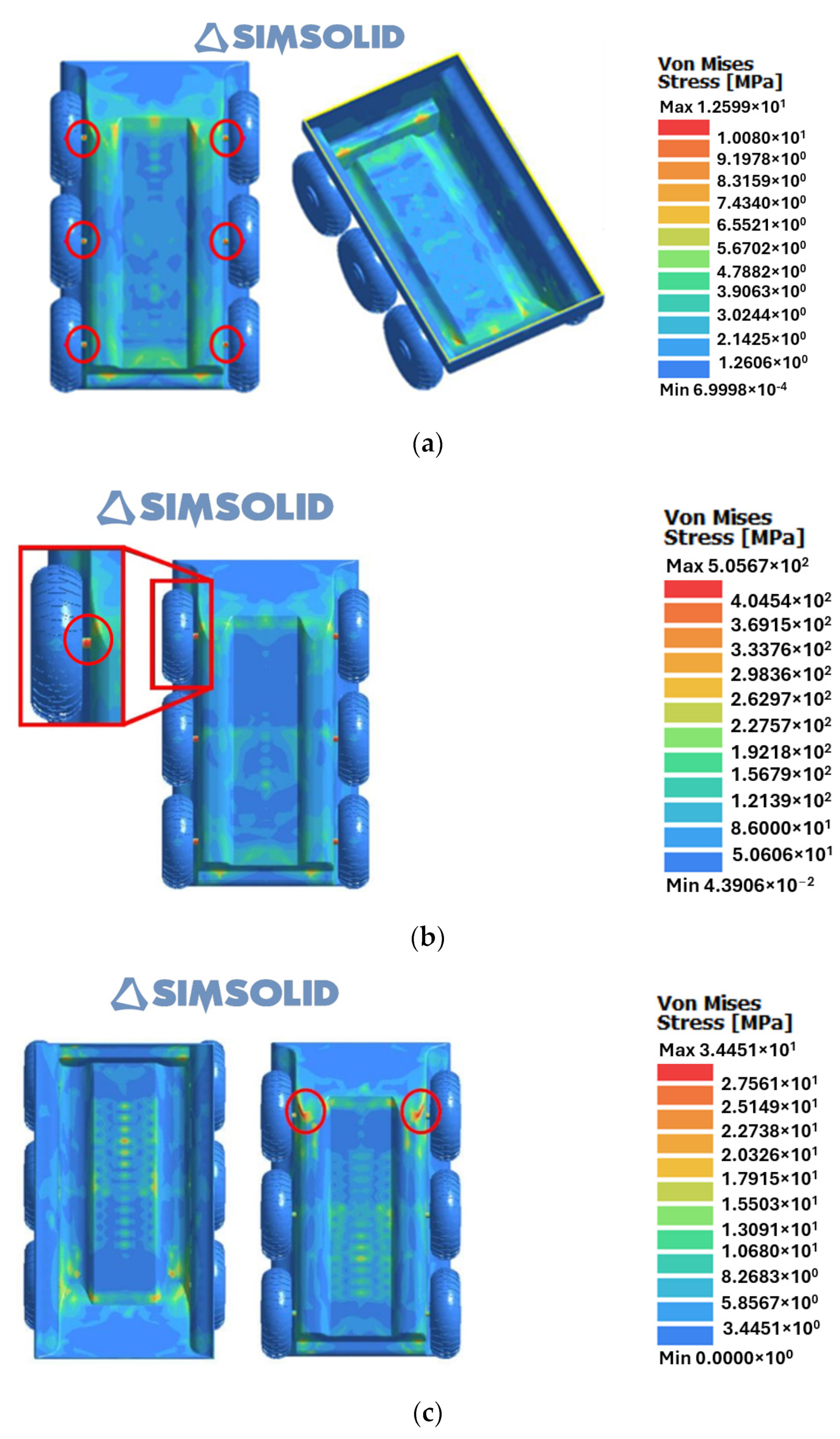
2.4.4. Static and Dynamic Structural Analysis
- Vehicle subject to the static loads (F) on the wheels;
- Vehicle subject to a static critical load (F) on the wheels;
- Vehicle subject to the dynamic step loads (F)on the wheels.
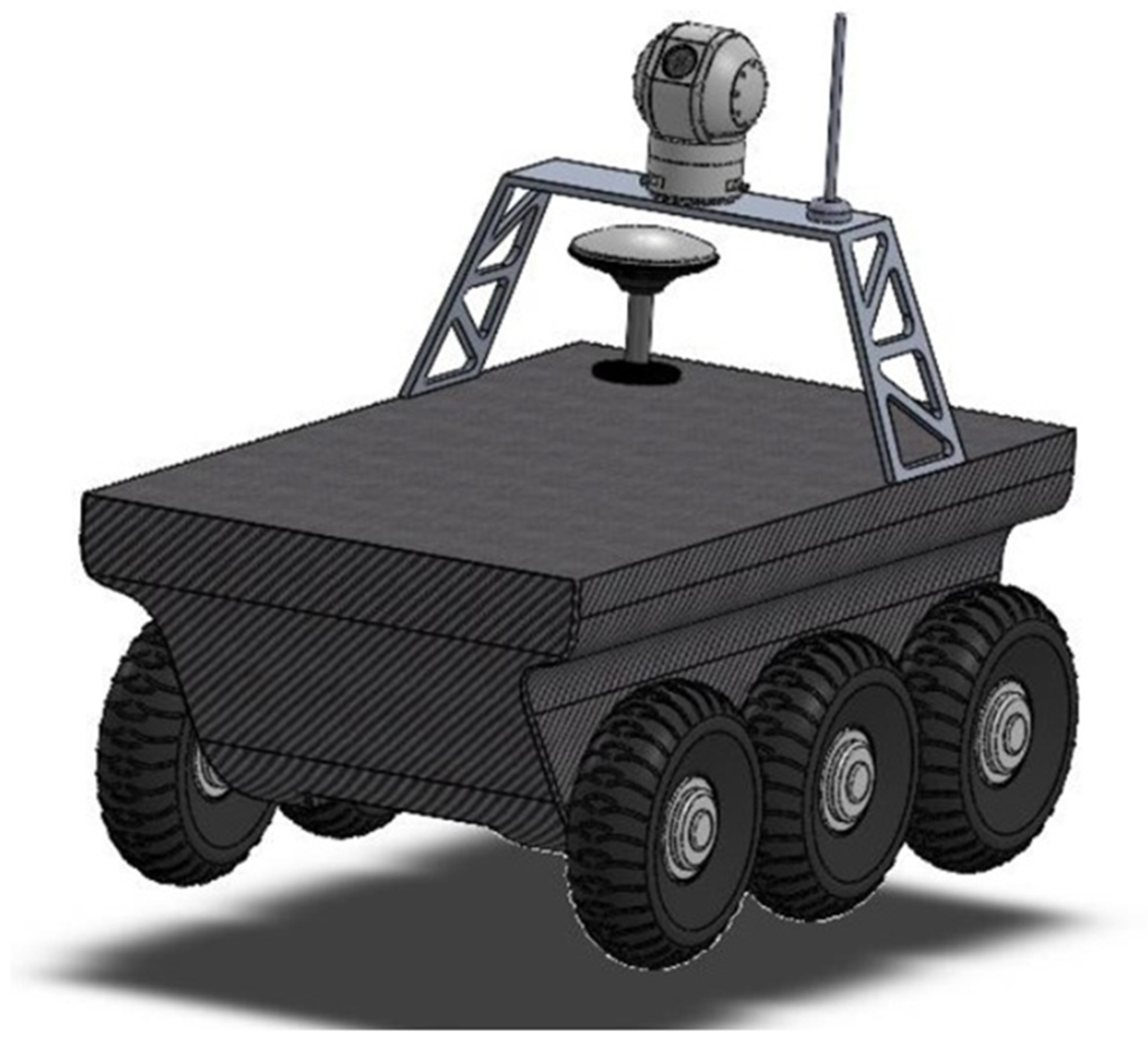
2.5. Conceptualization and Development
2.6. Set Final Specifications
3. Results
3.1. Identified Needs
- Support and increase capacity in civil and military operations;
- Accomplish its mission to reduce the risk for all personnel involved;
- Can operate efficiently on land and in water;
- Lightweight and small-sized vehicle so it can be easily transported and operated;
- Can equip different types of sensors according to the mission;
- Low production, maintenance, and operating costs.
3.2. Target Specifications
- Maximum weight ≃ 45 kg;
- Dedicated propulsion systems for land and water;
- Maximum land speed of 20 km/h;
- Maximum water speed of 8 kts;
- Floatability and stability in water;
- Autonomy > 1 h;
- Independent power sources;
- Hull made of resistant material;
- Production cost less than EUR 5 k.
3.3. Market Research
3.4. Static and Dynamic Structural Analysis
3.5. Final Specifications
- Maximum weight of 50 kg;
- Land traction 6 × 6;
- Maximum land speed of 20 km/h;
- Dedicated means of displacement in the water;
- Maximum water speed of 8 kts;
- Buoyancy and stability in water;
- Autonomy greater than 1 h;
- Four Li-ion batteries (80 Ah);
- Hull made of resistant material.
4. Conclusions and Final Remarks
Author Contributions
Funding
Data Availability Statement
Acknowledgments
Conflicts of Interest
References
- Tesla, N. Method of an Apparatus for Controlling Mechanism of Moving Vessels or Vehicles. U.S. Patent No. 613809, 8 November 1898. [Google Scholar]
- Wickersham, E.E. Land Torpedo. U.S. Patent No. 1407969A, 28 February 1922. [Google Scholar]
- Czapla, T.; Wrona, J. Technology Development of Military Applications of Unmanned Ground Vehicles BT. In Vision Based Systems for UAV Applications; Nawrat, A., Kuś, Z., Eds.; Springer International Publishing: Berlin/Heidelberg, Germany, 2013; pp. 293–309. ISBN 978-3-319-00369-6. [Google Scholar]
- Darrach, B. Meet Shaky, the First Electronic Person. Life Mag. 1970, 69, 58–68. [Google Scholar]
- Kuipers, B.; Feigenbaum, E.A.; Hart, P.E.; Nilsson, N.J. Shakey: From Conception to History. AI Mag. 2017, 38, 88–103. [Google Scholar] [CrossRef]
- Flynn, A.M. Redundant Sensors for Mobile Robot Navigation; MIT: Cambridge, MA, USA, 1985. [Google Scholar]
- Moravec, H. The Stanford Cart and CMU Rover. Robot. Inst. Carnegie-Mellon Tech. Rep. 1983, 71, 872–884. [Google Scholar] [CrossRef]
- Murphy, D.W.; Bott, J.P. The AirMobile Ground Security Surveillance System (AMGSSS). Unmanned Syst. 1995, 13, 22–28. [Google Scholar]
- Metz, C.D.; Everett, H.R.; Myers, S. Recent Developments in Tactical Unmanned Ground Vehicles. In Proceedings of the AUVS-92, Huntsville, AL, USA, 22–24 June 1992. [Google Scholar]
- Seetharaman, G.; Lakhotia, A.; Blasch, E.P. Unmanned Vehicles Come of Age: The DARPA Grand Challenge. Comput. (Long. Beach. Calif.) 2006, 39, 26–29. [Google Scholar] [CrossRef]
- Zhang, T.; Li, Q.; Zhang, C.; Liang, H.; Li, P.; Wang, T.; Li, S.; Zhu, Y.; Wu, C. Current Trends in the Development of Intelligent Unmanned Autonomous Systems. Front. Inf. Technol. Electron. Eng. 2017, 18, 68–85. [Google Scholar] [CrossRef]
- LeCun, Y.; Bengio, Y.; Hinton, G. Deep Learning. Nature 2015, 521, 436–444. [Google Scholar] [CrossRef]
- Izhar, M.I.; Jusoh, M.S.; Ahmad, R.; Ismail, M.S.; Ariffin, W.N.M. Performance Evaluation on Locomotion System, Body Size and Hull Design on Amphibious-Based Design of Unmanned Ground Vehicle Using Taguchi Method. AIP Conf. Proc. 2023, 2544, 40045. [Google Scholar] [CrossRef]
- Ragi, S.; Tan, C.; Chong, E.K.P. Guidance of Autonomous Amphibious Vehicles for Flood Rescue Support. Math. Probl. Eng. 2013, 2013, 528162. [Google Scholar] [CrossRef]
- Yue, G.; Ren, L.; Pan, Y.-T.; Guo, J.-Y. Research on Servo System of Unmanned Amphibious Rescue Vehicle for Sudden Flood Based on Intelligent Algorithms; IEEE: New York, NY, USA, 2023. [Google Scholar]
- Lim, J. Amphibious Locomotion with a Screw-Propelled Snake-like Robot; University of California: San Diego, CA, USA, 2023. [Google Scholar]
- Lynch, R.; Beknalkar, S.; Bishop, R.; Crow, A.; Donohue, B.; Pacheco-Cay, C.; Smith, A.; Mazzoleni, A.; Bryant, M. Design and Construction of a Terrestrial Testing Rig for Experimental Characterization of Multi-Terrain Screw-Propelled Vehicle Dynamics; American Society of Mechanical Engineers: New York, NY, USA, 2023. [Google Scholar]
- Wiseman, Y. Autonomous Vehicles. In Encyclopedia of Information Science and Technology, 5th ed.; IGI Global: Hershey, PA, USA, 2020; pp. 1–11. ISBN 9781799834793. [Google Scholar]
- Dudziak, A.; Droździel, P.; Stoma, M.; Caban, J. Market Electrification for BEV and PHEV in Relation to the Level of Vehicle Autonomy. Energies 2022, 15, 3120. [Google Scholar] [CrossRef]
- Krot, K.; Iskierka, G.; Poskart, B.; Gola, A. Predictive Monitoring System for Autonomous Mobile Robots Battery Management Using the Industrial Internet of Things Technology. Materials 2022, 15, 6561. [Google Scholar] [CrossRef]
- He, M.; Yue, X.; Zheng, Y.; Chen, J.; Wu, S.; Heng, Z.; Zhou, X.; Cai, Y. State of the Art and Future Trends in Obstacle-Surmounting Unmanned Ground Vehicle Configuration and Dynamics. Robotica 2023, 41, 2625–2647. [Google Scholar] [CrossRef]
- Liu, Q.; Li, Z.; Yuan, S.; Zhu, Y.; Li, X. Review on Vehicle Detection Technology for Unmanned Ground Vehicles. Sensors 2021, 21, 1354. [Google Scholar] [CrossRef]
- Ni, J.; Hu, J.; Xiang, C. A Review for Design and Dynamics Control of Unmanned Ground Vehicle. Proc. Inst. Mech. Eng. Part D J. Automob. Eng. 2020, 235, 1084–1100. [Google Scholar] [CrossRef]
- Ruslan, N.A.I.; Amer, N.H.; Hudha, K.; Kadir, Z.A.; Ishak, S.A.F.M.; Dardin, S.M.F.S. Modelling and Control Strategies in Path Tracking Control for Autonomous Tracked Vehicles: A Review of State of the Art and Challenges. J. Terramechanics 2023, 105, 67–79. [Google Scholar] [CrossRef]
- Test Operation Procedure, 2-2-540 Testing of Unmanned Ground Vehicle (UGV) Systems. (OMB No. 0704-0188) 30 June 2008, US Army. Available online: https://apps.dtic.mil/sti/tr/pdf/ADA482970.pdf (accessed on 13 June 2024).
- Hydrographic, U. Argonaut. Available online: https://www.ultrahydrographic.com/survey-platforms/argonaut/ (accessed on 15 July 2023).
- Robotics, C. Warthog. Available online: https://clearpathrobotics.com/warthog-unmanned-ground-vehicle-robot/ (accessed on 15 July 2023).
- Robotics, C. Moose. Available online: http://www.clearpathrobotics.com/assets/guides/melodic/moose/ (accessed on 15 July 2023).
- Milanion Agema. Available online: https://milaniongroup.com/agema-ugv/ (accessed on 15 July 2023).
- Marinha Portuguesa DEM 2018 REV 2021. Diretiva Estratégica da Marinha. 2018—Revisão 2021. 2021. Available online: https://www.marinha.pt/conteudos_externos/Diretiva_Estrategica_da_Marinha/DEM_2018_REV2021/files/basic-html (accessed on 5 May 2023).
- San-Miguel-Ayanz, J.; Oom, D.; Artes, T.; Viegas, D.X.; Fernandes, P.; Faivre, N.; Freire, S.; Moore, P.; Rego, F.; Castellnou, M. Forest Fires in Portugal in 2017. Sci. Disaster Risk Manag. 2020, 413–430. [Google Scholar] [CrossRef]
- Montiel, C.; Kraus, D.T. Best Practices of Fire Use: Prescribed Burning and Suppression: Fire Programmes in Selected Case-Study Regions in Europe; European Forest Institute: Joensuu, Finland, 2010; ISBN 978-952-5453-69-0. [Google Scholar]
- Ulrich, K.; Eppinger, S.; Yang, M.C. Product Design and Development, 7th ed.; McGraw Hill: New York, NY, USA, 2020. [Google Scholar]
- Evans, J.H. Basic Design Concepts. J. Am. Soc. Nav. Eng. 1959, 71, 671–678. [Google Scholar] [CrossRef]
- NATO NATO AAP-20—Nato Programme Management Framework (NATO Life Cycle Model). 2015. Available online: https://standards.globalspec.com/std/9970689/aap-20 (accessed on 13 June 2024).
- Jones, E.; Childers, R. Contemporary College Physics, 3rd ed.; McGraw-Hill Education: New York, NY, USA, 2001; ISBN 0072415126. [Google Scholar]
- Moore, C.S. The Principles of Naval Architecture Series: Intact Stability; The Society of Naval Architects and Marine Engineers: Jersey City, NJ, USA, 2010; ISBN 0939773740. [Google Scholar]
- Apanovitch, V. The Method of External Finite Element Approximations, 1st ed; Independently published, 2021; ISBN 979-8467137773. [Google Scholar]
- Matweb ZoltekTM PX35. Available online: https://www.matweb.com/search/datasheet.aspx?matguid=a04e355696af4cb3896e704b5500664f&ckck=1 (accessed on 15 July 2023).
- Matweb Aluminum Alloy 7075 T6. Available online: https://asm.matweb.com/search/SpecificMaterial.asp?bassnum=ma7075t6 (accessed on 15 July 2023).
- Law, S.S.; Bu, J.Q.; Zhu, X.Q.; Chan, S.L. Vehicle Axle Loads Identification Using Finite Element Method. Eng. Struct. 2004, 26, 1143–1153. [Google Scholar] [CrossRef]
- Widiyanto, I.; Sutimin, S.; Laksono, F.B.; Prabowo, A.R. Structural Assessment of Monocoque Frame Construction Using Finite Element Analysis: A Study Case on a Designed Vehicle Chassis Referring to Ford GT40. Procedia Struct. Integr. 2021, 33, 27–34. [Google Scholar] [CrossRef]
- Ary, A.K.; Prabowo, A.; Imaduddin, F. Structural Assessment of Alternative Urban Vehicle Chassis Subjected to Loading and Internal Parameters Using Finite Element Analysis. J. Eng. Sci. Technol. 2020, 15, 1999–2022. [Google Scholar]

| Name/Country | Picture | Dimensions, mm (L × W × H) | Weight, kg | Traction (Land/Water) | Speed (Land/Water) | Autonomy |
|---|---|---|---|---|---|---|
| Argonaut [26]/UK |  | 3000 × 1450 × 1800 | 450 | Wheels 8 × 8 and mountable tracks + 2 propellers | 25.7 km/h 3.9 kts (water) | 12 h |
| Warthog [27]/Canada |  | 1520 × 1380 × 830 | 280 | Wheels 4 × 4 | 18 km/h NA (water) | 3 h |
| Moose [28]/Canada |  | 2960 × 1550 × 1140 | 1590 | Wheels 8 × 8 | 30 km/h NA (water) | 6 h |
| Agema 6 [29]/UAE |  | 2440 × 1470 × 1290 | 442 | Wheels 6 × 6 | 35 km/h 2.7 kts (water) | 6 h |
| Agema 8 [29]/UAE | 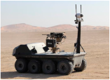 | 3020 × 1470 × 2990 | 602 | Wheels 8 × 8 | 29 km/h 2.7 kts (water) | 6 h |
| Components | Cost |
|---|---|
| Batteries | EUR 1200 |
| Land propulsion (wheels, motor, and shaft included) | EUR 720 |
| Water propulsion | EUR 135 |
| Remote control | EUR 300 |
| Telemetry | EUR 80 |
| Electric cables | EUR 100 |
| Carbon-reinforced fiber | EUR 1000 |
| Mold of the hull | EUR 300 |
| Man labor | EUR 1000 |
| Total | EUR 4835 |
Disclaimer/Publisher’s Note: The statements, opinions and data contained in all publications are solely those of the individual author(s) and contributor(s) and not of MDPI and/or the editor(s). MDPI and/or the editor(s) disclaim responsibility for any injury to people or property resulting from any ideas, methods, instructions or products referred to in the content. |
© 2024 by the authors. Licensee MDPI, Basel, Switzerland. This article is an open access article distributed under the terms and conditions of the Creative Commons Attribution (CC BY) license (https://creativecommons.org/licenses/by/4.0/).
Share and Cite
Policarpo, H.; Lourenço, J.P.B.; Anastácio, A.M.; Parente, R.; Rego, F.; Silvestre, D.; Afonso, F.; Maia, N.M.M. Conceptual Design of an Unmanned Electrical Amphibious Vehicle for Ocean and Land Surveillance. World Electr. Veh. J. 2024, 15, 279. https://doi.org/10.3390/wevj15070279
Policarpo H, Lourenço JPB, Anastácio AM, Parente R, Rego F, Silvestre D, Afonso F, Maia NMM. Conceptual Design of an Unmanned Electrical Amphibious Vehicle for Ocean and Land Surveillance. World Electric Vehicle Journal. 2024; 15(7):279. https://doi.org/10.3390/wevj15070279
Chicago/Turabian StylePolicarpo, Hugo, João P. B. Lourenço, António M. Anastácio, Rui Parente, Francisco Rego, Daniel Silvestre, Frederico Afonso, and Nuno M. M. Maia. 2024. "Conceptual Design of an Unmanned Electrical Amphibious Vehicle for Ocean and Land Surveillance" World Electric Vehicle Journal 15, no. 7: 279. https://doi.org/10.3390/wevj15070279
APA StylePolicarpo, H., Lourenço, J. P. B., Anastácio, A. M., Parente, R., Rego, F., Silvestre, D., Afonso, F., & Maia, N. M. M. (2024). Conceptual Design of an Unmanned Electrical Amphibious Vehicle for Ocean and Land Surveillance. World Electric Vehicle Journal, 15(7), 279. https://doi.org/10.3390/wevj15070279