Article

Harmonic Resonance Mechanisms and Influencing Factors of Distributed Energy Grid-Connected Systems

1
New Electrical Metrology Technology Laboratory of State Grid Corporation of China (Marketing Service Center of State Grid Jiangsu Electric Power Co., Ltd.), Nanjing 210019, China
2
School of Electrical Engineering, Southeast University, Nanjing 210096, China
*
Author to whom correspondence should be addressed.
World Electr. Veh. J. 2024, 15(7), 287; https://doi.org/10.3390/wevj15070287
Submission received: 29 May 2024 / Revised: 19 June 2024 / Accepted: 25 June 2024 / Published: 26 June 2024

Abstract

:
With the rapid development of global energy transformation and new power system, ensuring the stability of distributed energy grid connections is the key to maintaining the reliable operation of the whole power system. This paper constructs detailed impedance models of grid-following (GFL) and grid-forming (GFM) inverters using a harmonic linearization method and thoroughly investigates the mechanisms of resonance when inverters are connected to the grid, as well as the impact of model parameters on the stability of the grid system. This paper also briefly analyzes the scenario where distributed energy and electric vehicles are integrated into the grid simultaneously, demonstrating that grid system stability can be ensured in complex grid situations through reasonable parameter design. Lastly, the accuracy of the proposed impedance models and analysis is verified through MATLAB/Simulink simulations.

1. Introduction

Distributed energy mainly includes solar energy, wind energy, fuel cells and biological energy, which has the advantages of energy saving and cleaning. It plays a significant role in the global energy structure transition. As grid connection technology continues to improve, the penetration rate of distributed energy is continually increasing worldwide, especially in regions with rapidly growing electricity demands or weaker grid infrastructures. The integration of distributed energy contributes significantly to enhancing the operational efficiency of the grid, increasing the security of power systems, and promoting the development of environmentally friendly power systems. It has become a vital force in driving the transformation of modern power systems and achieving green development goals [1]. However, the extensive integration of distributed energy can greatly affect the safety and stability of power system operations and the quality of electric power. Distributed energy is interfaced with the grid through inverters. At certain frequencies, the impedance of the grid matches the output impedance of the inverters, potentially causing resonance. This interaction between inverters and the grid can lead to severe distortions in grid voltage and current, significantly degrading the quality of electric power and even causing system instability. Therefore, the issues of power quality and system stability arising from the interaction between grid-connected inverters and the grid cannot be overlooked [2,3,4,5]. With the proliferation of electric vehicles, the increasing number of charging stations will significantly impact the distribution network due to the harmonics they generate. Therefore, it is necessary to consider the harmonic impact of electric vehicle integration in grid-connected systems.
When analyzing the stability of grid-connected inverters, common methods include the state-space method [6,7] and impedance analysis method [8]. The state-space method requires frequent updates of the system state-space model to reflect new system structures and parameter states. Due to this characteristic, using the state-space method for system analysis becomes particularly cumbersome [9]. Consequently, some scholars have proposed the impedance analysis method, which separates the inverter and the grid into two independent subsystems for impedance modeling. The impedance analysis method simplifies the analysis of complex systems and can directly determine system stability via Bode plots. It also requires only the re-modeling of the changing components when parameters change, leaving the rest of the system unaffected [10]. Moreover, when modeling the impedance of grid-connected inverters, traditional small-signal linearization methods are not applicable due to the periodic changes in their steady-state operating trajectories [11]. Therefore, this paper employs the harmonic linearization method for impedance modeling of inverters during grid connection.
The mainstream control methods for inverters currently fall into two categories: grid-following (GFL) and grid-forming (GFM). Ref. [12] utilized the harmonic linearization impedance modeling method to construct the positive and negative sequence impedance models of GFL inverter with a phase-locked loop (PLL). However, it only considered a single L-filter, whereas the LCL-type GFL inverter, due to its superior filtering performance, is more widely used [13,14]. Therefore, it is necessary to model the LCL-type GFL inverter. Reference [15] presented the sequence impedance models of two types of LCL-type grid-connected GFL inverters with different current sampling schemes. The proposed positive and negative sequence impedance models are applied to analyze the stability and resonance between the inverters and the grid. However, the effects of circuit parameters and PLL parameters on stability are not analyzed. In contrast to traditional GFL inverters, GFM inverters controlled by virtual synchronous generators (VSG) can emulate the behavior of conventional synchronous generators. By adjusting control strategies to simulate inertia and damping, these inverters can enhance grid stability and add system inertia during grid integration, increasingly becoming a focal point in grid-connected power generation technologies and widely adopted [16,17]. Ref. [18] utilized the harmonic linearization method to model the impedance of GFM, and discusses the stability of a weak grid-connected system in detail according to the Nyquist criterion. The article points out that the impedance model of a single-phase VSG has resistive/inductive features at low frequencies, while it exhibits inductive–capacitive (LC) characteristics at high frequencies. However, these studies did not explore the stability of various types of inverters simultaneously connecting to the grid under complex conditions. Moreover, using impedance analysis for system parameter optimization is regarded as an effective approach to enhance grid system stability. Ref. [19,20] highlight that through meticulous parameter adjustments, system stability and adaptability can be significantly enhanced. Refs. [19] proposed a systematic design method of PLL controller parameters, which effectively reduce the negative effect of PLL on current control. Ref. [20] proposed a parameter design method for inverter connection to weak grids with a focus on stability margins. By using the Routh criterion and the impedance ratio between the grid impedance and the inverters impedance, the proportional gain of the DC bus voltage controller is designed to achieve the required gain margin (GM) for the system.
This paper aims to analyze the influence of distributed energy on power quality, especially the resonance problem. By modeling the impedance of GFL and GFM, the resonant characteristics of these inverters are analyzed when they are connected to the power grid. Initially, a detailed impedance modeling of GFL inverters is conducted in conjunction with the frequency characteristics of PLL, and the influence of PLL parameters on the stability of the grid-connected system is studied. Subsequently, a similar method is applied to model the impedance of voltage-controlled GFM inverters, investigating their interaction with the grid and proposing guidelines for parameter design. Finally, by choosing parameters wisely, the paper ensures that the connection of GFL inverter, GFM inverter and electric vehicles to the grid does not lead to resonances, thus ensuring the efficient and stable operation of the electrical power system. The theoretical analysis and design methods presented in this paper are validated through simulation.
The paper is arranged as follows. In Section 2 and Section 3, impedance models of GFL and GFM are, respectively, established, followed by parameter analysis. Section 4 investigates the scenario where both inverters and electric vehicles are connected to the grid simultaneously. In Section 5, simulations are conducted to validate the proposed theories and analyses.

2. Impedance Modeling Analysis of GFL Inverter

2.1. Typical GFL Inverter Impedance Modeling

Figure 1 presents the structural block diagram of a typical GFL inverter. It includes the DC input voltage Udc, the voltage at the point of common coupling (PCC), represented as ugabc, the inverter-side inductance, L1, and the grid-side inductance, L2. Additionally, the diagram features a filter capacitor Cf and a series damping resistor Rd, alongside the grid impedance Zg. The current control loop regulator is denoted as Gi(s). The output phase angle signal from the PLL θPLL is used for coordinate transformation. The references for the d-axis and q-axis currents are indicated as idr and iqr, respectively. The three-phase voltage reference signal umabc is modulated through PWM to achieve the duty cycle that controls the modulation of the GFL inverter.
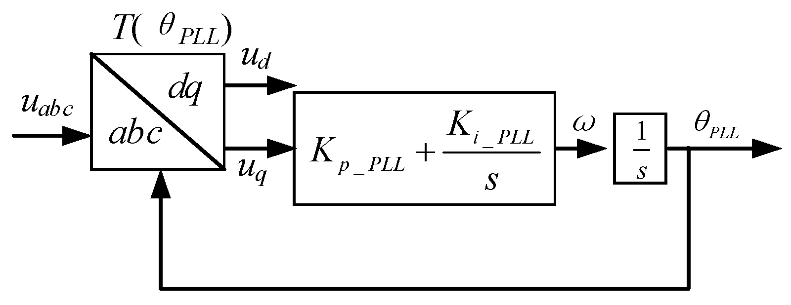
The GFL inverter utilizes the PLL to continuously track the phase of the grid voltage. Therefore, any disturbance in the grid voltage initially impacts the phase angle of the PLL, subsequently affecting the current regulator. Thus, it is essential to model and analyze the frequency characteristics of the PLL first. This paper employs a synchronous reference frame phase-locked loop (SRF-PLL) [21], and its control diagram is depicted in Figure 2.
The process begins with sampling the voltage at the PCC of the grid, which, after undergoing an abc/dq transformation, outputs ud and uq. In this paper, a PI controller is utilized for the PLL with the transfer function Kp_PLL + Ki_PLL/s. After passing through the PI section, the uq generates a grid frequency signal. Integrating this frequency signal yields the phase lock angle. Hence, the transfer function of the PLL is expressed as HPLL(s) = (Kp_PLL + Ki_PLL/s)/s. This paper applies the harmonic linearization method for small-signal modeling of the SRF-PLL. The introduction of a small signal voltage disturbance at the PCC induces a disturbance Δ θ in the phase lock angle, which can be expressed as θ P L L = θ 1 + Δ θ . θ 1 is the steady-state phase lock angle under no voltage disturbance. The coordinate transformation module depicted in Figure 2 can be described as follows.
T ( θ PLL ) = 2 3 cos ( θ 1 + Δ θ ) cos ( θ 1 2 π / 3 + Δ θ ) cos ( θ 1 + 2 π / 3 + Δ θ ) sin ( θ 1 + Δ θ ) sin ( θ 1 2 π / 3 + Δ θ ) sin ( θ 1 + 2 π / 3 + Δ θ ) 1 / 2 1 / 2 1 / 2         = 2 3 cos ( θ 1 ) cos ( θ 1 2 π / 3 ) cos ( θ 1 + 2 π / 3 ) sin ( θ 1 ) sin ( θ 1 2 π / 3 ) sin ( θ 1 + 2 π / 3 ) 1 / 2 1 / 2 1 / 2 cos ( Δ θ ) sin ( Δ θ ) 0 sin ( Δ θ ) cos ( Δ θ ) 0 0 0 1         = T ( θ 1 ) · T ( Δ θ )
In the described system, T(θ1) represents the transformation module for the steady-state phase lock angle, and T(∆θ) denotes the transformation module for the phase angle disturbance. Taking phase A voltage as an example, if a positive sequence small-signal voltage disturbance is introduced at the PCC and transformed into the frequency domain, the expression can be derived as follows:
V ˙ g a [ f ] = V ˙ 1 ,     f = ± f 1 V ˙ p ,     f = ± f p
V ˙ 1 represents the fundamental wave voltage expression in the frequency domain, V ˙ 1 = V 1 / 2 , and V1 is the peak voltage of the grid. V ˙ p is the expression for the positive sequence disturbance voltage in the frequency domain, V ˙ p = V p 2 e ± j φ v p , and Vp is the positive-sequence disturbance voltage peak value. φ v p is the phase of the positive sequence disturbance voltage, and fp is the frequency of the positive sequence disturbance voltage. Assuming
u d q = u a b c · T ( θ 1 ) · T ( Δ θ ) = u d q 1 · T ( Δ θ )
By applying the T(θ1) transformation module, the three-phase voltage is converted into udq1 in the frequency domain.
V ˙ d 1 [ f ] = V ˙ 1 ,         d c V ˙ p ,         f = ± ( f p f 1 )
V ˙ q 1 [ f ] = 0 ,         d c j V ˙ p ,         f = ± ( f p f 1 )
After the first coordinate transformation, udq1(t) undergoes a second transformation by T(∆θ) to obtain udq(t), which is expressed as follows:
u d ( t ) = cos Δ θ · u d 1 ( t ) + sin Δ θ · u q 1 ( t ) u q ( t ) = sin Δ θ · u d 1 ( t ) + cos Δ θ · u q 1 ( t )
Since the disturbance in the PLL is minor, ∆θ is approximately zero, implying that cos(∆θ) ≈ 1, sin(∆θ) ≈ 0. When transformed into the frequency domain, the result can be expressed as follows:
V ˙ d [ f ] = V ˙ d 1 [ f ] + Δ θ ˙ [ f ] V ˙ q 1 [ f ] V ˙ q [ f ] = Δ θ ˙ [ f ] V ˙ d 1 [ f ] + V ˙ q 1 [ f ]
Δ θ ˙ [ f ] is the frequency domain expression of the phase angle disturbance ∆θ, and represents the convolution process. Assuming GPLL represents the relationship between Δ θ ˙ [ f ] and V ˙ p , it can be specifically described as in Equation (8).
Δ θ ˙ [ f ] = G P L L [ f ] V ˙ p , f = ± ( f p f 1 )
Substituting into Equation(7), therefore,
V ˙ q [ f ] = { G P L L [ f ] V 1 j } V ˙ P , f = ± ( f p f 1 )
At the frequency fp and because Δ θ ˙ [ f ] = H P L L [ f ] V ˙ q [ f ] , we can derive the following expression
Δ θ ˙ [ f ] = j H P L L [ f ] 1 + V 1 H P L L [ f ] V ˙ P , f = ± ( f P f l )
From this, the closed-loop transfer function Tp(s) of cos(θPLL) with V ˙ p can be determined as
T p ( s ) = 1 2 · H P L L ( s j ω 1 ) 1 + V 1 H P L L ( s j ω 1 )
Similarly, the transfer function Tn(s) of cos(θPLL) with V ˙ n can be determined as
T n ( s ) = 1 2 · H P L L ( s + j ω 1 ) 1 + V 1 H P L L ( s + j ω 1 )
After completing the analysis of the PLL frequency characteristics, we can derive the output impedance model of the GFL considering the PLL. The grid current is sampled and transformed into the dq-axis, with its frequency domain expression given below:
I ˙ d [ f ] = I 1 cos φ i 1 ,     d c 2 j I 1 sin φ il T p ( ± j 2 π f p ) V ˙ p + I ˙ p , f = ± ( f p f 1 ) ± 2 j I 1 sin φ i 1 T n ( ± j 2 π f n ) V ˙ n + I ˙ n , f = ± ( f n + f 1 )
I ˙ q [ f ] = I 1 sin φ i 1 ,     d c ± 2 j I 1 cos φ il T p ( ± j 2 π f p ) V ˙ p + j I ˙ p , f = ± ( f p f 1 ) 2 j I 1 cos φ i 1 T n ( ± j 2 π f n ) V ˙ n + j I ˙ n , f = ± ( f n + f 1 )
In this analysis, Tp(s) and Tn(s) represent the PLL transfer functions for positive and negative sequence disturbances, respectively. V ˙ p and V ˙ n are the frequency domain expressions for the positive and negative sequence voltage disturbances, while I ˙ p and I ˙ n are those for the positive and negative sequence current disturbances. fp, and fn denote the frequencies of the positive and negative sequence voltage disturbances, and φ i 1 is the phase of the fundamental voltage. As shown in Figure 1, by employing a closed-loop current control Gi(s) on idq, the frequency domain expression for umdq can be obtained.
V ˙ m d [ f ] = T 1 ( θ ) I ˙ d r [ f ] I ˙ d [ f ] · G i [ f ] V ˙ m q [ f ] = T 1 ( θ ) I ˙ d r [ f ] I ˙ q [ f ] · G i [ f ]
Transforming this into the abc-axis and inserting it into the frequency domain expression of the main circuit’s average model, and by utilizing the relationship between small-signal voltage stimulation and the output current response, the positive and negative sequence output impedances of the GFL, Zp(s) and Zn(s) can be derived, respectively shown as Equation (16) and Equation (17).
Z p ( s ) = L 1 s + L 2 s + L 1 L 2 C f s 3 / ( C f R d s + 1 ) + G i ( s j ω l ) 1 + L l C f s 2 / ( C f R d s + 1 ) [ G i ( s j ω l ) + V l / ( I l e j φ il ) ] T p ( s ) I l e j φ il
Z n ( s ) = L 1 s + L 2 s + L 1 L 2 C f s 3 / ( C f R d s + 1 ) + G i ( s + j ω l ) 1 + L l C f s 2 / ( C f R d s + 1 ) [ G i ( s + j ω l ) + V l / ( I l e j φ il ) ] T n ( s ) I l e j φ il

2.2. Stability Analysis

Upon acquiring the positive and negative sequence output impedances of the GFL inverter, the stability during grid integration can be evaluated using an impedance-based stability criterion. Let fi be the intersection frequency of the magnitudes of grid impedance and inverter impedance, and define the phase margin φ pm as
φ p m = 180 ° ( φ z g _ f i φ i n v _ f i )
Here, φ z g _ f i , φ i n v _ f i are the phase angles of the grid impedance and inverter impedance at fi, respectively. If φ pm < 0°, it indicates that the system is unstable. If 0° < φ pm < 30°, it suggests that the system has a small stability margin and poor robustness, making it susceptible to resonance when disturbed by harmonic sources. Engineering practices often require maintaining a phase margin of 30° to ensure stable operation of grid-connected systems. Next, we analyze the interaction between the GFL inverter and the grid based on this criterion. The parameters for the GFL inverter are presented in Table 1.
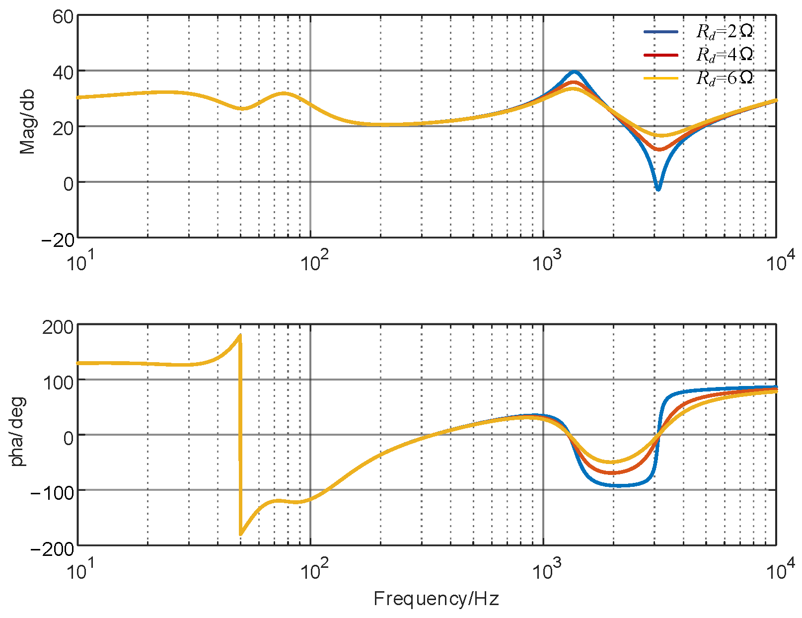
Figure 3 shows the impedance curves for the GFL inverter and the grid with grid impedances of 2 mH and 12 mH, respectively. From Figure 3, it is evident that the positive and negative sequence impedances of the GFL inverter differ only in the low frequency range, while they align in the mid to high frequency range. The GFL inverter exhibits capacitive characteristics in the low- to mid-frequency range, whereas the grid shows distinctly inductive characteristics. As the grid impedance increases, making the grid weaker, the GFL inverter is more likely to interact unstably with the grid, leading to resonance. With a grid impedance of 12 mH, the grid impedance curve intersects the positive sequence output impedance of the GFL at 154 Hz, where the phase margin is only 16.05°, which does not meet the stability conditions required for engineering practice and is likely to lead to resonance. When the grid impedance is 2 mH, the intersection with the GFL positive sequence output impedance occurs at 1858 Hz; due to insufficient phase margin, the system is unstable, leading to high-frequency resonance. Thus, it is necessary to take measures to increase the phase margin at high frequencies, one of which is increasing Rd, a simple and effective measure. High-frequency Zp(s) and Zn(s) curves being identical, the effect of Rd on the Zp(s) curve is studied uniformly. As shown in Figure 4, Rd has no impact on the Zp(s) curve in the low- to mid-frequency range, but as Rd increases, the phase angle curve rises in the high-frequency range, providing sufficient phase margin to avoid the risk of high-frequency resonance.

2.3. Influence of PLL Bandwidth on GFL Impedance Curve

First, the TPLL(s) transfer function can be defined as
T PLL ( s ) = V 1 H PLL ( s ) 1 + V 1 H PLL ( s )
When substituted into HPLL(s) = (Kp_PLL + Ki_PLL/s)/s, we obtain
T PLL ( s ) = V 1 K p _ P L L s + V 1 K i _ P L L s 2 + V 1 K p _ P L L s + V 1 K i _ P L L = 2 ξ ω n s + ω n 2 s 2 + 2 ξ ω n s + ω n 2
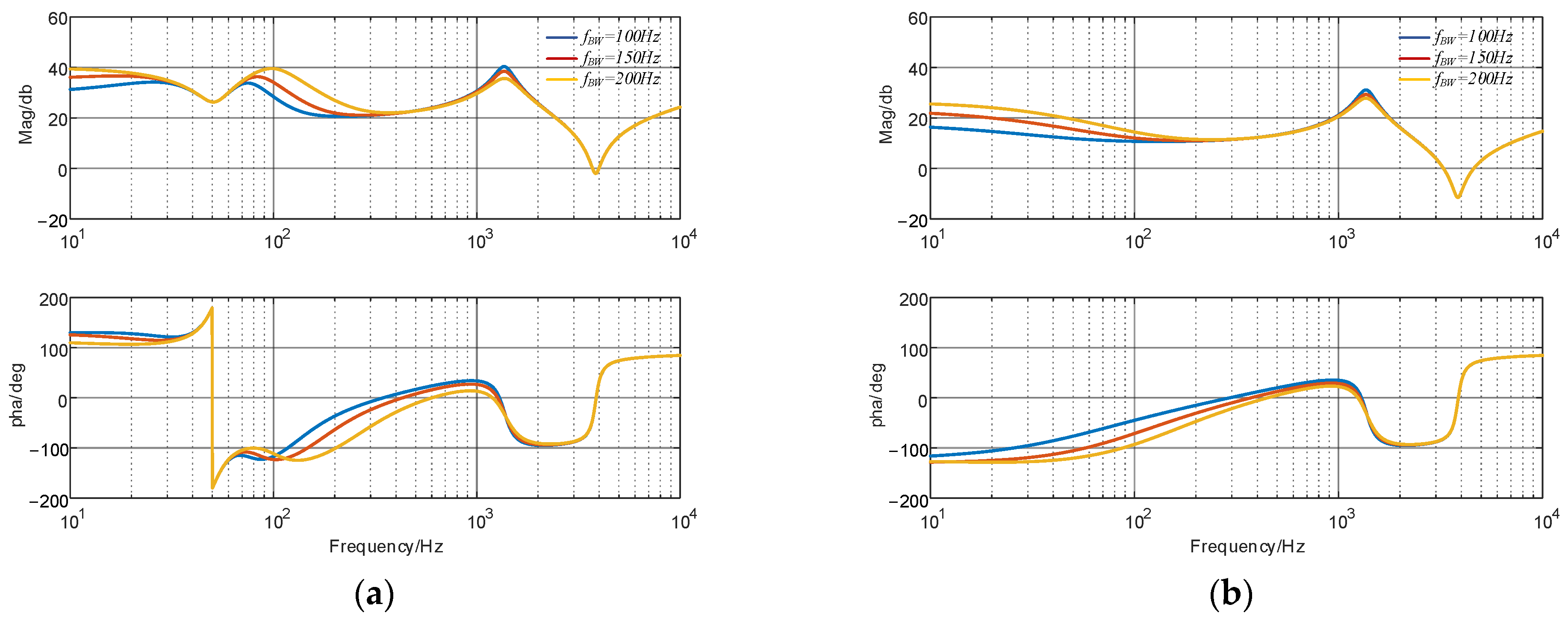
Here, ζ represents the damping ratio and ωn the natural frequency. As a typical second-order system, considering overshoot and settling time, a damping ratio of ζ = 0.707 is selected. The bandwidth of the PLL, denoted as ωBW, can be derived as
K i _ p l l = 2 ξ 2 ω B W 2 + ω B W 2 1 + 4 ξ 4 V 1
K p _ p l l = 4 ξ 2 K i _ p l l V 1
A lower PLL bandwidth results in poorer tracking performance of the fundamental frequency voltage, whereas a too-high bandwidth may cause instability in the grid-connected system. Balancing dynamic performance and system stability, the PLL bandwidth is ideally set between 100 Hz to 250 Hz. Figure 5 illustrates the impact of PLL bandwidth on the positive and negative sequence impedances, respectively. It is evident that as the PLL bandwidth increases, the impedance magnitude of the GFL within 1 kHz increases, and the phase angle decreases, enlarging the capacitive region. Consequently, there is an increased likelihood of resonance occurring with the grid.

3. Impedance Modeling Analysis of GFM Inverter

3.1. Typical GFM Inverter Impedance Modeling

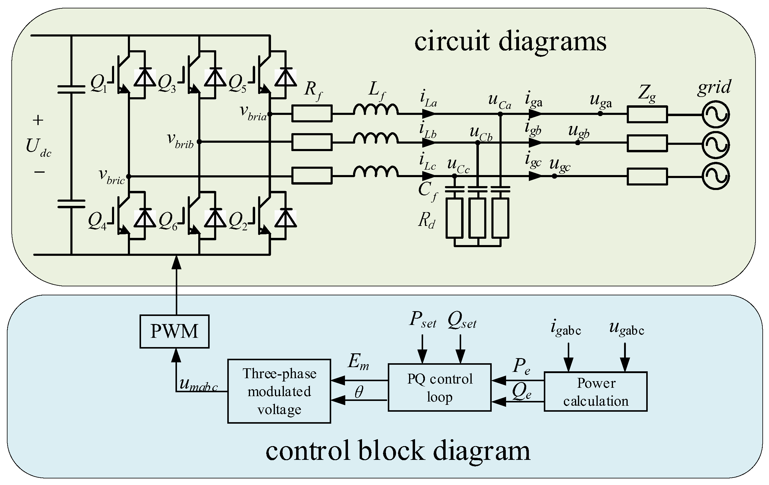
Figure 6 depicts a typical GFM inverter control circuit. In the diagram, Udc represents the DC input voltage, ugabc denotes the voltage at the PCC, Lf is the filter inductor, Rf is the series resistor, Cf and Rd are, respectively, the filter capacitor and the series resistor, and Zg is the grid impedance.
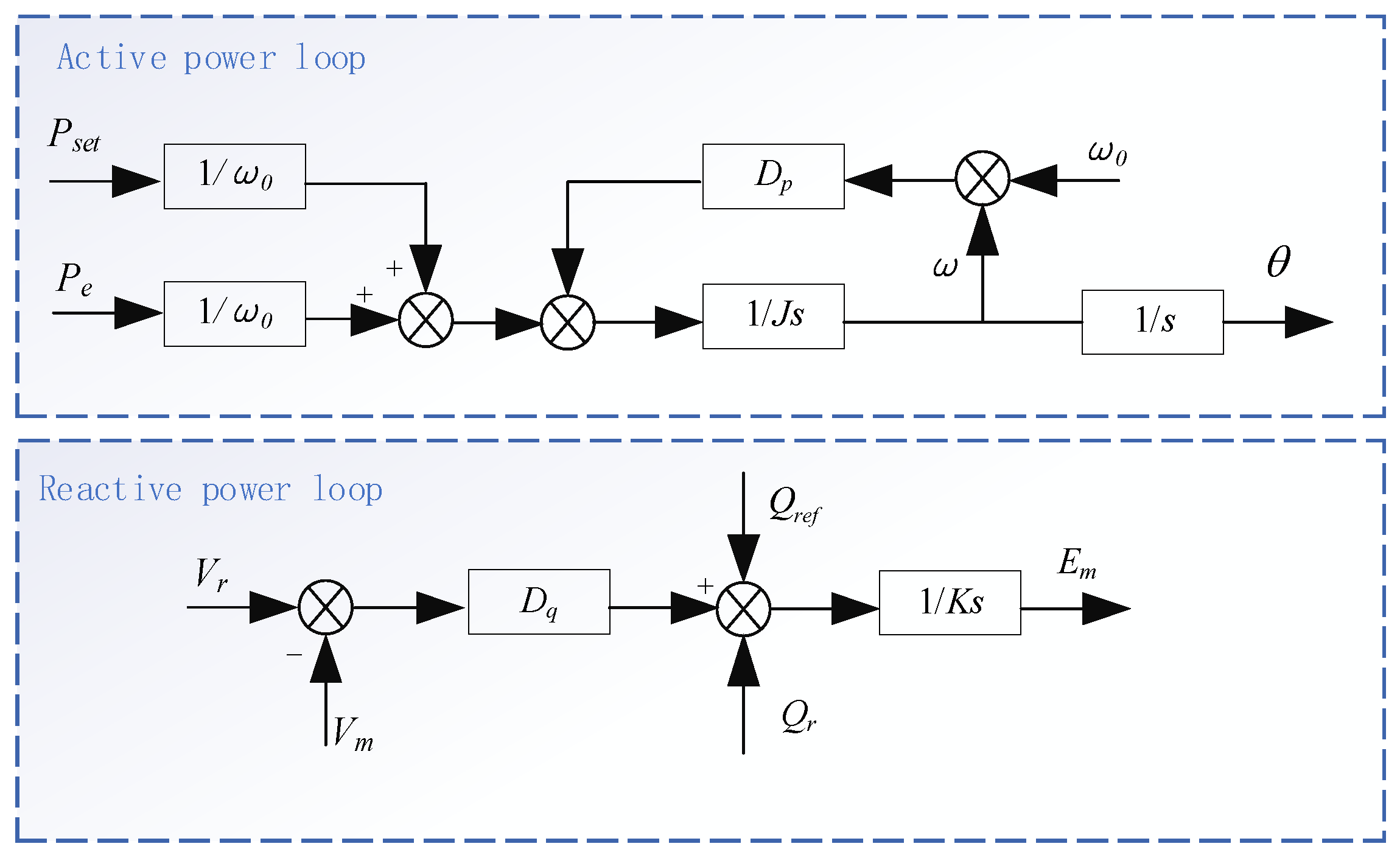
Power calculations are performed by sampling the three-phase voltage ugabc and current igabc at the PCC to obtain the real power Pe and reactive power Qe. These measurements, along with the set values for real power Pset and reactive power Qset, are input into the PQ control loop to determine the excitation internal potential Em and the output phase signal θ. The specific PQ control loop is shown in Figure 7, where J represents virtual inertia; Dp is the droop coefficient; ω0 is the standard angular frequency of the grid, ω is the angular frequency generated by the GFM inverter; K is the integral coefficient of the excitation regulator; Dq is the voltage regulation coefficient; Vr and Vm are, respectively, the set voltage amplitude and the voltage amplitude output by the VSG. The values of θ and Em are used in three-phase modulation to compute umabc, and the inverter’s closed-loop control is completed via PWM.
Similar to the impedance modeling for GFL inverter, a harmonic linearization technique is used to establish the GFM inverter impedance model. By injecting positive and negative sequence voltage disturbances of different frequency at the PCC, the corresponding small-signal currents are generated. The relationship between these disturbances can be used to derive the positive and negative sequence output impedances Zp(s) and Zn(s) of the GFM inverter. Zp(s) and Zn(s) considering reactive loop dynamics are shown below.
Z p ( s ) = 0.75 V 1 e j φ e [ T ( s j 2 π f 1 ) + E m N ( s j 2 π f 1 ) / ω 0 ] + ( s L f + R f ) 0.75 I 1 e j ( φ e φ i , 1 ) [ T ( s j 2 π f 1 ) E m N ( s j 2 π f 1 ) / ω 0 ] + R ( s )
Z n ( s ) = 0.75 V 1 e j φ e [ T ( s + j 2 π f 1 ) + E m N ( s + j 2 π f 1 ) / ω 0 ] + ( s L f + R f ) 0.75 I 1 e j ( φ e φ i , l ) [ T ( s + j 2 π f 1 ) E m N ( s + j 2 π f 1 ) / ω 0 ] + R ( s )
V1 represents the amplitude of the fundamental voltage, and φ is the phase difference between the bridge potential and the inverter output voltage, set as φ e= φ + π/2. I1 and φ i,1 are the amplitude and initial phase angle of the fundamental frequency current, respectively. The transfer function N(s) is defined as N(s) = s(Js + Dp), where T(s) = 1/Ks, and R(s) is expressed as R(s) =(LfCfs2 + RfCfs + RdCfs + 1)/(RdCfs + 1).
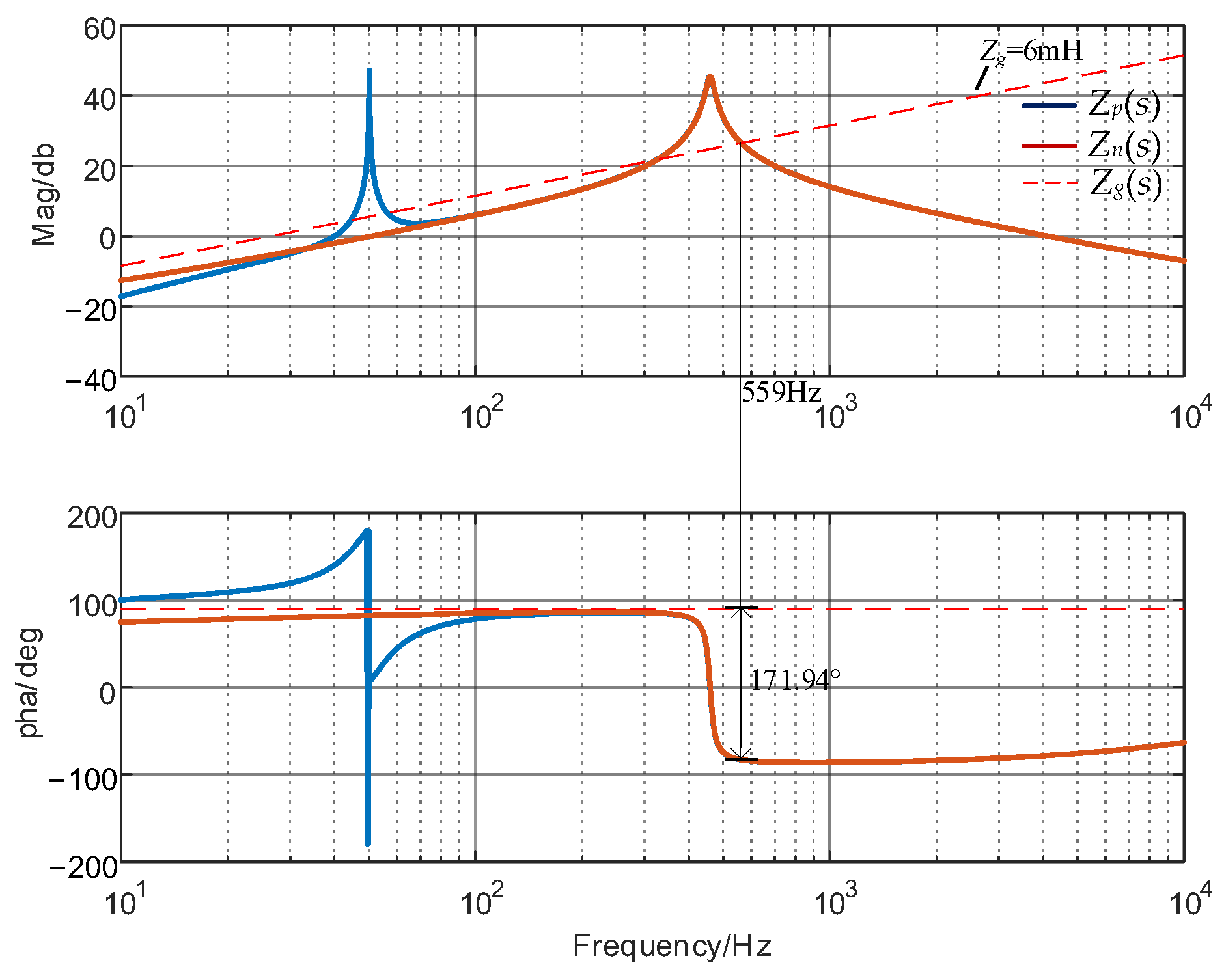
This section uses the GFM inverter impedance model to analyze its grid interconnection stability. Specific parameters of the GFM inverter are listed in Table 2, with the grid impedance Zg = 6 mH.
As shown in Figure 8, the GFM inverter impedance characteristics are predominantly inductive at low to mid frequencies, which prevents resonance with the similarly inductive grid, hence offering stronger stability at these frequencies compared to the GFL inverter. However, with increasing frequency, the phase angle of the GFM inverter impedance exhibits a sudden shift of 180°, becoming capacitive and introducing the risk of resonance. At 559 Hz, the impedance magnitude curves of the GFM inverter and the grid intersect, and the phase margin is a mere 8.06°, indicating a susceptibility to instability. It is noteworthy that the grid typically carries 11th background harmonics. Resonance at these frequencies could lead to significant resonant currents at the PCC. Additionally, with the increasing prevalence of electric vehicles (EVs) and the expansion of charging infrastructure, the impact of EV charging stations on the grid is significant [22]. Commonly, EV chargers use 12-pulse uncontrollable machines, which inject harmonics of the form 12k ± 1 into the grid [23]. If these chargers operate during a resonance condition, they could cause substantial harmonic voltages at the PCC, leading to system instability. Therefore, it is crucial to design the GFM inverter parameters carefully to avoid resonance phenomena.

3.2. Influence of Parameters on GFM Inverter Impedance Curve

This section investigates the effects of the circuit parameters Lf, Cf, and Rd on the impedance curve of the GFM inverter, specifically focusing on Zp(s) since the curves for Zp(s) and Zn(s) align beyond 100 Hz. As shown in Figure 9, increasing Lf or Cf results in a decrease in the frequency at which a sudden phase shift occurs in Zp(s), and simultaneously increases the corresponding magnitude. To prevent resonance between the GFM inverter and the common background harmonics present in the grid, it is advisable not to excessively increase Lf or Cf. This avoids shifting the resonance peak into lower frequency bands, or they should be adjusted appropriately to ensure that the resonance peak does not coincide with common harmonic frequencies. According to Figure 9c, increasing Rd significantly enhances the phase angle of Zp(s) at higher frequencies, thereby improving the robustness of the grid-connected system. Consequently, increasing Rd is an effective strategy to avoid system resonance, ensuring greater stability and integrity of the grid interconnection.

4. Analysis of Concurrent Grid Integration of Inverters and Electric Vehicles

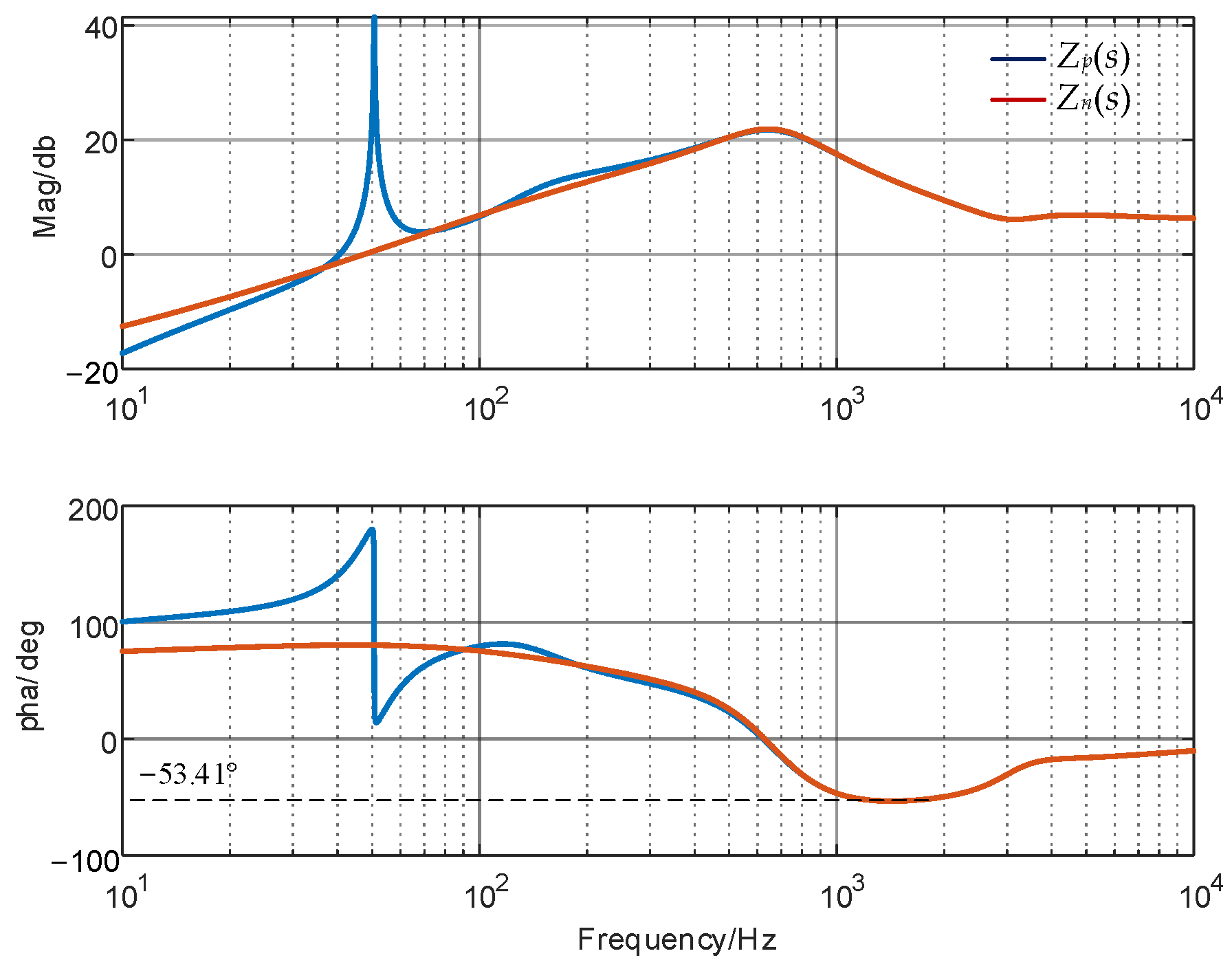
In this section, we analyze the scenario where both GFL and GFM inverters are connected to the grid simultaneously. Based on the principles of parameter adjustment previously discussed, the Rd in the three-phase synchronous grid-following inverter is set to 6 Ω, while in the GFM inverter, Rd is adjusted to 2 Ω and the Cf to 30 μF. The remaining parameters are consistent with those listed in Table 1 and Table 2. Under these settings, the combined impedance curve of GFL and GFM inverters when paralleled in the grid is shown in Figure 10. When interacting with the grid impedance, the system maintains a minimum phase margin of 36.59°. Notably, at this time, the 12k ± 1 order harmonic generated by electric vehicles connected to the grid will also not pose a resonance risk. This analysis confirms the system’s stability and operational safety when both inverters and electric vehicles are concurrently connected to the grid.

5. Simulations

This paper utilizes MATLAB/Simulink R2023b simulations to validate the accuracy of the impedance modeling method proposed. The parameters for both GFL and GFM inverters are selected according to Table 1 and Table 2.
Initially, the GFL impedance model is validated. With the grid impedance Zg set to 2 mH, as shown in Figure 11a, there is a significant harmonic current near 1858 Hz, and the grid current waveform is illustrated in Figure 11b. This confirms that high-frequency resonance occurs when GFL is connected to the grid, aligning with theoretical analyses.
Next, the accuracy of the GFM impedance model is verified. With the grid impedance set to 6 mH, as displayed in Figure 12a, significant harmonic currents are observed around 557 Hz, and the corresponding grid current waveform is shown in Figure 12b. The system experiences resonance and poor current quality.
To simulate the operational scenario of an electric vehicle charging station, 5 A of 11th and 13th harmonic currents are injected at the PCC. Figure 13 indicate that upon injecting a small amount of harmonic current, significant harmonic voltages arise at the coupling point, leading to system resonance and instability. These simulations validate the correctness of the impedance model and theoretical analysis established in this study.
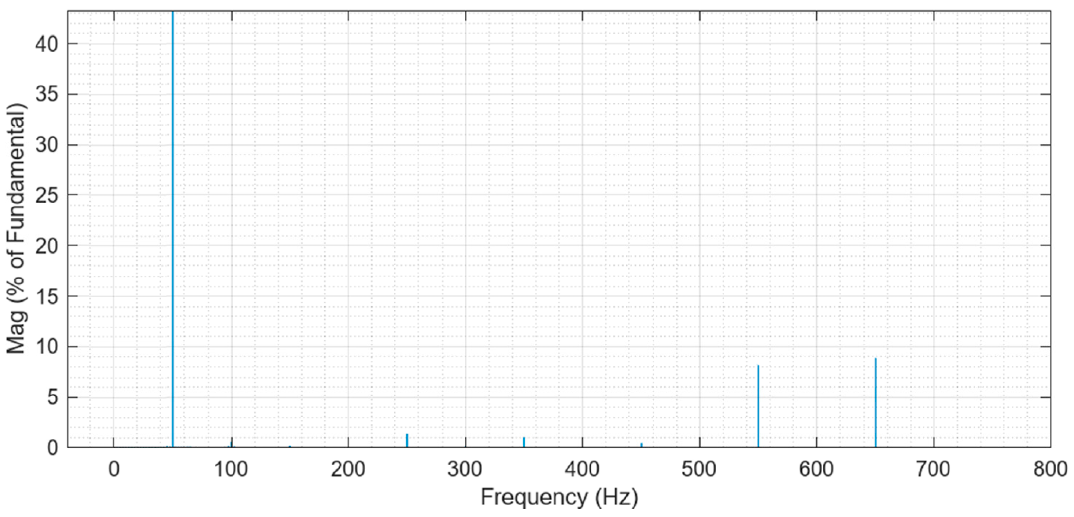
Finally, the stability of complex systems is verified through simulation. GFL and GFM are simultaneously connected to the grid, and parameters from Section 2 are employed. At the PCC, 10% of the 5th and 7th harmonic background voltages are injected, along with 5 A of 11th and 13th harmonic currents induced by the EV charging stations. The simulation results, as shown in Figure 14, demonstrate that the system remains stable and does not experience resonance even in the presence of multiple harmonics. This validates the correctness of the theoretical approach and the rationality of the parameter design presented in this study.

6. Conclusions

This paper investigates the resonance issues associated with the integration of distributed energy into the grid. By utilizing harmonic linearization techniques, impedance models for both GFL and GFM inverters were systematically constructed, and the specific impacts of various model parameters on the stability of the grid-connected system were thoroughly analyzed. The correctness of the theoretical analysis presented in this study is validated through simulations.
It was found that the GFL inverter exhibits capacitive characteristics at mid-to-low frequencies, making it more susceptible to resonance phenomena in weak, inductive grid environments. At higher frequencies, resonance can be avoided by increasing the series damping resistance. Furthermore, this study also detailed the significant impact of the bandwidth of the PLL on the impedance characteristics of GFL inverter, noting that increased PLL bandwidth decreases system stability.
The impedance model of GFM inverter, in contrast to the GFL inverter, shows inductive characteristics at mid-to-low frequencies, making it less likely to resonate with an inductive grid. However, at higher frequencies, GFM inverter impedance curve undergoes a sudden phase shift, which may resonate with the grid, posing a risk of system instability. To address this issue, the paper proposes reasonable parameter adjustment strategies to effectively reduce the risk of resonance.
This paper simulates the complex scenario of GFL and GFM inverters along with an EV charging station simultaneously connected to the grid. By designing the parameters appropriately, the stability of the system is ensured.
In future research, there will be a deeper exploration into the impact of advanced structures and control methods of GFL and GFM on impedance models and stability. Specifically, we aim to address preventive measures against potential harmonic resonance issues that may arise. By delving into these areas, we anticipate enriching and expanding the current understanding of how advanced structural configurations and control strategies can enhance the overall robustness and efficiency of power grid systems. This investigation holds promise for advancing the field and contributing to the development of more resilient energy networks capable of meeting future demands.

Author Contributions

Conceptualization, M.X. and Z.L.; methodology, S.L.; software, X.Q.; validation, T.X.; writing, T.X. and Z.Z. All authors have read and agreed to the published version of the manuscript.

Funding

This research was funded by State Grid Jiangsu Electric Power Company Technology Project (Grant No. J2023140).

Data Availability Statement

The data supporting the conclusions of this article will be made available by the authors on request.

Conflicts of Interest

The authors declare no conflicts of interest. Minrui Xu, Zhixin Li, Shufeng Lu are employees of Marketing Service Center of State Grid Jiangsu Electric Power Co., Ltd. The paper reflects the views of the scientists and not the company.

References

  1. Zou, Z.; Tang, J.; Buticchi, G.; Liserre, M. Stabilization of Distribution Grids With High Penetration of Renewables: The Path From Decentralized Control to a Centralized One. IEEE Ind. Electron. Mag. 2024, 18, 17–31. [Google Scholar] [CrossRef]
  2. Wu, W.; Liu, Y.; He, Y.; Chung, H.S.H.; Liserre, M.; Blaabjerg, F. Damping Methods for Resonances Caused by LCL-Filter-Based Current-Controlled Grid-Tied Power Inverters: An Overview. IEEE Trans. Ind. Electron. 2017, 64, 7402–7413. [Google Scholar] [CrossRef]
  3. Alawasa, K.M.; Mohamed, Y.A.-R.I. A Simple Approach to Damp SSR in Series-Compensated Systems via Reshaping the Output Admittance of a Nearby VSC-Based System. IEEE Trans. Ind. Electron. 2015, 62, 2673–2682. [Google Scholar] [CrossRef]
  4. Sun, J. Impedance-Based Stability Criterion for Grid-Connected Inverters. IEEE Trans. Power Electron. 2011, 26, 3075–3078. [Google Scholar] [CrossRef]
  5. Ren, Y.; Wang, X.; Chen, L.; Min, Y.; Li, G.; Wang, L.; Zhang, Y. A Strictly Sufficient Stability Criterion for Grid-Connected Converters Based on Impedance Models and Gershgorin’s Theorem. IEEE Trans. Power Deliv. 2020, 35, 1606–1609. [Google Scholar] [CrossRef]
  6. Kroutikova, N.; Hernandez-Aramburo, C.A.; Green, T.C. State-space model of grid-connected inverters under current control mode. IET Electr. Power Appl. 2007, 1, 329–338. [Google Scholar] [CrossRef]
  7. Kwon, J.; Wang, X.; Bak, C.L.; Blaabjerg, F. The modeling and harmonic coupling analysis of multiple-parallel connected inverter using harmonic state space (HSS). In Proceedings of the 2015 IEEE Energy Conversion Congress and Exposition (ECCE), Montreal, QC, Canada, 20–24 September 2015. [Google Scholar]
  8. Rygg, A.; Molinas, M. Apparent impedance analysis: A small-signal method for stability analysis of power electronic-based systems. IEEE J. Emerg. Sel. Top. Power Electron. 2017, 5, 1474–1486. [Google Scholar] [CrossRef]
  9. Wang, Y.; Wang, X.; Blaabjerg, F.; Chen, Z. Harmonic Instability Assessment Using State-Space Modeling and Participation Analysis in Inverter-Fed Power Systems. IEEE Trans. Ind. Electron. 2016, 64, 806–816. [Google Scholar] [CrossRef]
  10. Gui, Y.; Zheng, J.; Liu, Z.; Gou, Y.; Ding, Y. Improved Impedance Stability Analysis of Power Electronic System Considering Harmonic Source. In Proceedings of the 2022 5th International Conference on Renewable Energy and Power Engineering (REPE), Beijing, China, 28–30 September 2022. [Google Scholar]
  11. Sun, J. Small-signal methods for electric ship power systems. In Proceedings of the 2009 IEEE Electric Ship Technologies Symposium, Baltimore, MD, USA, 20–22 April 2009. [Google Scholar]
  12. Cespedes, M.; Sun, J. Impedance Modeling and Analysis of Grid-Connected Voltage-Source Converters. IEEE Trans. Power Electron. 2014, 29, 1254–1261. [Google Scholar] [CrossRef]
  13. Fang, T.; Shen, S.; Zhang, L.; Jin, Y.; Huang, C. Capacitor Current Feedback With Phase-Lead Compensator to Eliminate Resonant Frequency Forbidden Region for LCL-Type Grid-Connected Inverter in Weak Grid. IEEE J. Emerg. Sel. Top. Power Electron. 2021, 9, 5581–5596. [Google Scholar] [CrossRef]
  14. Nishida, K.; Ahmed, T.; Nakaoka, M. A Novel Finite-Time Settling Control Algorithm Designed for Grid-Connected Three-Phase Inverter With an LCL-Type Filter. IEEE Trans. Ind. Appl. 2014, 50, 2005–2020. [Google Scholar] [CrossRef]
  15. Yu, Y.; Li, H.; Li, Z. Impedance modeling and stability analysis of LCL-type grid-connected inverters with different current sampling schemes. In Proceedings of the 2016 IEEE 8th International Power Electronics and Motion Control Conference (IPEMC-ECCE Asia), Hefei, China, 22–26 May 2016. [Google Scholar]
  16. Wu, W.; Zhou, L.; Chen, Y.; Luo, A.; Dong, Y.; Zhou, X.; Xu, Q.; Yang, L.; Guerrero, J.M. Sequence-Impedance-Based Stability Comparison Between VSGs and Traditional Grid-Connected Inverters. IEEE Trans. Power Electron. 2019, 34, 46–52. [Google Scholar] [CrossRef]
  17. Lou, G.; Yang, Q.; Gu, W.; Zhang, J. An improved control strategy of virtual synchronous generator under symmetrical grid voltage sag. Int. J. Electr. Power Energy Syst. 2020, 121, 106093. [Google Scholar] [CrossRef]
  18. Zhang, X.; Chen, J.; Chen, X. Impedance Modeling and Stability Analysis of Weak-Grid Interfaced Single-Phase VSG. In Proceedings of the 2019 22nd International Conference on Electrical Machines and Systems (ICEMS), Harbin, China, 11–14 August 2019. [Google Scholar]
  19. Zhu, D.; Zhou, S.; Zou, X.; Kang, Y. Improved Design of PLL Controller for LCL-Type Grid-Connected Converter in Weak Grid. IEEE Trans. Power Electron. 2020, 35, 4715–4727. [Google Scholar] [CrossRef]
  20. Wang, K.; Yuan, X.; Li, S.; Wu, X. Stability-Margin-Oriented Key Parameter Design for Voltage-Source Rectifiers in Weak Power Grids With Inductive Impedance. IEEE Open J. Ind. Electron. Soc. 2021, 2, 511–527. [Google Scholar] [CrossRef]
  21. Gonzalez-Espin, F.; Figueres, E.; Garcera, G. An Adaptive Synchronous-Reference-Frame Phase-Locked Loop for Power Quality Improvement in a Polluted Utility Grid. IEEE Trans. Ind. Electron. 2012, 59, 2718–2731. [Google Scholar] [CrossRef]
  22. Huang, Z.; Fang, B.; Deng, J. Multi-objective optimization strategy for distribution network considering V2G-enabled electric vehicles in building integrated energy system. Prot. Control. Mod. Power Syst. 2020, 5, 1–8. [Google Scholar] [CrossRef]
  23. Lan, D.; Wu, Y.; Soeiro, T.B.; Granello, P.; Qin, Z.; Bauer, P. 12-pulse Rectifier with DC-Side Buck Converter for Electric Vehicle Fast Charging. In Proceedings of the IECON 2022–48th Annual Conference of the IEEE Industrial Electronics Society, Brussels, Belgium, 17–20 October 2022. [Google Scholar]
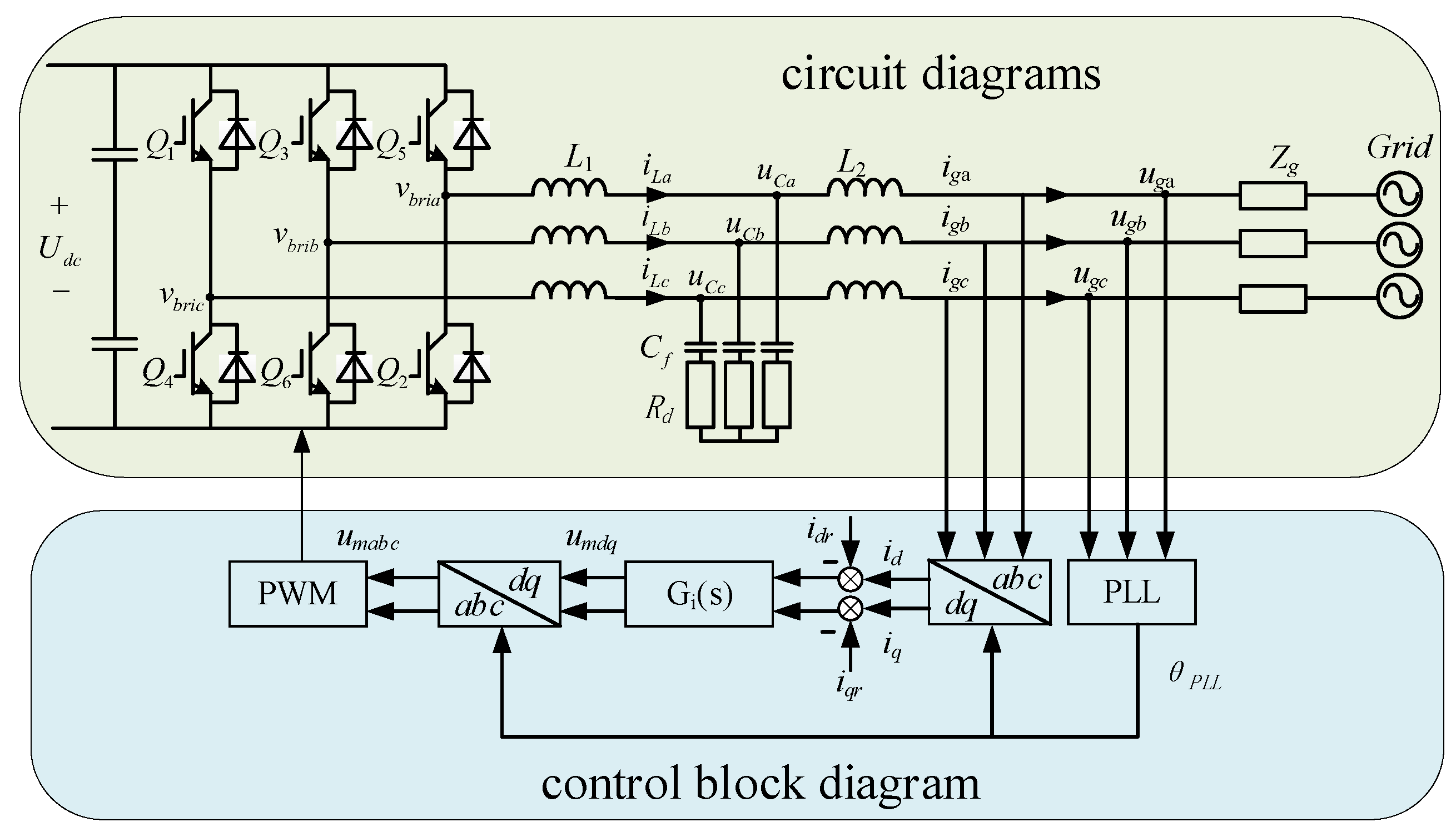
Figure 1. Typical GFL inverter structural block diagram.
Wevj 15 00287 g001
Figure 2. PLL control block diagram.
Wevj 15 00287 g002
Figure 3. Interaction between GFL inverter and grid.
Wevj 15 00287 g003
Figure 4. Impact of parameter Rd on the Zp(s) curve.
Wevj 15 00287 g004
Figure 5. Impact of PLL on Impedance Curve: (a) Zp(s); (b) Zn(s).
Wevj 15 00287 g005
Figure 6. GFM Structure and control circuit diagram.
Wevj 15 00287 g006
Figure 7. PQ power control block diagram.
Wevj 15 00287 g007
Figure 8. Interaction of GFM inverter with grid.
Wevj 15 00287 g008
Figure 9. Impact of parameters on the Zp(s) Curve: (a) the impact of the parameter Lf; (b) the impact of the parameter Cf; (c) the impact of the parameter Rd.
Wevj 15 00287 g009
Figure 10. Combined positive and negative sequence impedances curve.
Wevj 15 00287 g010
Figure 11. GFL inverter grid-connected current result: (a) FFT analysis; (b) current waveform.
Wevj 15 00287 g011
Figure 12. GFM inverter grid-connected current result: (a) FFT analysis; (b) current waveform.
Wevj 15 00287 g012
Figure 13. GFM inverter grid-connected voltage result after EV connection: (a) FFT analysis; (b) voltage waveform.
Wevj 15 00287 g013
Figure 14. FFT analysis of grid current in complex situations result.
Wevj 15 00287 g014
Table 1. GFL inverter impedance model simulation parameters.
System ParametersValues
Grid Phase Voltage Peak (V1)311 V
DC Voltage (Vdc)700 V
Inverter Rated Current (I)30 A
Phase-Locked Loop Coefficients (Kp_PLL, Ki_PLL)2.4, 929.4
Inductance on the Inverter Side (L1)2 mH
Inductance on the Grid Side (L2)0.5 mH
Filter Capacitor (Cf)6.8 μF
Series Damping Resistor (Rd)2 Ω
Switching Frequency (fs)10 kHz
Sampling Frequency (fsw)20 kHz
Table 2. GFM inverter impedance model simulation parameters.
System ParametersValues
Grid Phase Voltage Peak (V1)311 V
Virtual Inertia (J)0.02
Droop Coefficient (Dp)10
Excitation Controller Integral Coefficient (K)6
Voltage Regulation Coefficient (Dq)200
DC Voltage (Vdc)700 V
Inverter Power (P)10 kW
Inductor’s Series Resistor (Rf)0.2 Ω
Filter Inductor (Lf)3 mH
Filter Capacitor (Cf)40 μF
Capacitor’s Series Resistor (Rd)0.2 Ω
Switching Frequency (fs)10 kHz
Sampling Frequency (fsw)20 kHz
Disclaimer/Publisher’s Note: The statements, opinions and data contained in all publications are solely those of the individual author(s) and contributor(s) and not of MDPI and/or the editor(s). MDPI and/or the editor(s) disclaim responsibility for any injury to people or property resulting from any ideas, methods, instructions or products referred to in the content.