1. Introduction
The vector control method is widely used in current control systems driven by motors, and the decoupling process and closed-loop control of permanent magnet synchronous motor (PMSM) vector control require the constant acquisition of position and speed of rotor motors. Compared with the traditional method of using position sensors to obtain speed and position, position sensorless control significantly reduces system costs and volume, avoiding many problems such as position sensor failure under extreme working conditions.
At present, the position sensorless control technology of permanent magnet synchronous motors is mainly applied in two conditions: zero–low speed and medium–high speed, and there is currently no control method that can achieve stable operation covering the full-speed domain. The position sensorless control technology in the medium-to-high-speed range is mainly based on the mathematical model of the motor itself, the back electromotive force of the motor is calculated through mathematical solving methods, and the back electromotive force is used to calculate the position and speed information of the rotor. The position sensorless control at zero–low speed mainly utilizes the salient polarity of the motor. Due to the independence of salient polarity from the operating state of the motor, it can be used to estimate the rotor position information of the motor during stationary or low-speed operation, the methods mainly including inductance measurement, voltage pulse, high-frequency signal injection, etc. Compared with other methods, the high-frequency signal injection method has better performance, so it is more widely studied and applied.
According to the different ways of injecting high-frequency signals, high-frequency signal injection methods can be divided into the rotating high-frequency signal injection method, the pulse vibration high-frequency signal injection method, and the square wave signal injection method. The idea of the pulse vibration high-frequency signal injection method is to inject high-frequency signals in the estimated rotational coordinate system. After injecting a high-frequency cosine signal into the estimated -axis, the high-frequency response current of the estimated -axis contains position error information of the rotor, which is proportional to the sine value of the error signal. The rotor position information can be solved using phase-locked loops or Luenberger observers. Therefore, this article focuses on the research of position-sensorless motor control technology using the pulse vibration high-frequency signal injection method at zero and low speed.
At present, the implementation of the pulse vibration high-frequency injection method mainly faces the following key issues: (1) the selection of the injected signal; (2) the analysis of response signals; and (3) process signals to obtain position and speed information. Domestic and foreign scholars have conducted in-depth research and analysis on these issues. References [
1,
2] analyze the operating performance of the system by analyzing the positive and negative sequence currents after injecting pulse vibration signals, compare the impact of the signal-to-noise ratio and harmonic components on system performance, and analyze and predict the reasons and effects of amplitude loss of the injected signals and the bias caused by current modulation on estimation accuracy, system bandwidth, and the estimated stability. Reference [
3] also increases the injected frequency by injecting positive and negative signals and improves the position observer to reduce estimation errors. Reference [
4] improves the injected signal in order to remove the filter of the current closed loop, proposing that within a fixed period, the signal is injected, and the position information is simultaneously calculated in half of the period while the signal is not injected, and then it is calculated for the current closed loop in the other half in order to remove the low-pass filter in the current closed loop and increase the bandwidth. Reference [
5] proposes a new signal modulation method whereby the signal is directly modulated to eliminate delays caused by filters. Traditional signal modulation, on the other hand, involves low-pass filtering by multiplying a sine signal by the same injected frequency to extract the position difference signal. References [
6,
7] consider the adverse situation of the inverter’s nonlinearity, analyze the parameter changes in the inverter after injecting high-frequency signals, and propose how to increase optimization. Reference [
8] determines the initial position of the rotor by injecting high-frequency pulses phase by phase and comparing the response currents. This method is twice as accurate as the traditional four-pole Hall sensor.
When applying the pulse vibration high-frequency injection method, due to the inherent defects of the algorithm, the rotor may converge to a position that deviates by 180° from the actual position. Therefore, in engineering applications, it is necessary to perform magnetic pole determination, generally using the saturation effect of the direct-axis magnetic circuit to achieve this determination. References [
9,
10] apply the Taylor expansion to the straight-axis magnetic circuit curve and determine the magnetic pole information by analyzing the coefficients of its quadratic components. References [
11,
12] obtains magnetic pole information by comparing the amplitudes of the response high-frequency current after injecting a high-frequency sinusoidal voltage under the condition of injecting positive and negative DC currents. After obtaining the position difference signal, traditional position, and speed, observers use a digital phase-locked loop for observation. References [
13,
14] propose a new observer to achieve this goal. The aforementioned research delves into intricate issues regarding the high-frequency pulse injection method, proposing novel theoretical approaches to address encountered challenges. However, further in-depth investigation is warranted for certain detailed aspects. As previously discussed, during the implementation of high-frequency pulse injections, inherent algorithmic deficiencies may result in discrepancies between the convergent position and the actual position. While the initial position determination can be rectified assessing magnetic pole polarity, encountering abrupt speed changes due to specific operating conditions may lead to failure in position estimation caused by the lag of the position observer during operation. The research on these issues is evidently insufficient. Hence, this study analyzes and investigates the impacts of phase-locked loop observer parameter selection and dual-loop PI parameter selection on system operation, proposing design methodologies for these parameters.
Regarding the injection signal, there is also a notable lack of information on parameter selection. Throughout the implementation of the high-frequency pulse injection method, the primary signals required for sampling are current signals. Starting from current deviations, this paper analyzes the effects of this factor on the system, thereby deducing parameter selection methods for injection signals tailored to specific systems. Given the injection of high-frequency signals, various frequency signals within the motor necessitate filtering. The introduction of filters cannot be overlooked in its impact on the system. To address the bandwidth reduction caused by filters, scholars have proposed multiple approaches. Similarly, this paper analyzes the effects of filters on the system and provides principles for general filter design as well as parameter selection methods.
Therefore, this article develops its analysis combining the implementation process of the pulse vibration high-frequency injection method, taking into account the deviation between the convergence position and the actual position caused by the algorithm’s inherent defects, and applies magnetic pole judgments to correct the initial position judgment. Considering that when the speed suddenly changes due to special operating conditions during operation, the hysteresis of the position observer can cause the failure of position estimation during operation, this article focuses on studying the influence of parameter selection of phase-locked loop observers and double closed-loop PI on system operation and proposes parameter design methods.
Section 2 of this article focuses on orientation control without position sensors; and
Section 3 primarily introduces the detection of the initial position. Due to the nonlinearity of the position error signal inputted by the phase-locked loop, the estimated position deviates by 180° from the actual deviation. The saturation characteristics of the direct-axis magnetic circuit are utilized for magnetic pole determination.
Section 4 analyzes and studies the phase-locked loop observer, compares and contrasts two methods for magnetic pole determination, and proposes a parameter design method suitable for velocity loop PI in pulse vibration high-frequency injections. Finally, the feasibility and rationality of the above methods are verified through simulation and experiments.
2. Position Sensorless Field-Oriented Control Using High-Frequency Pulse Vibration Injection
The pulse vibration high-frequency voltage injection method entails injecting a sinusoidal voltage signal into the estimated synchronous rotating coordinate system. At this point, the motor is an equivalent inductance model, so it will respond to high-frequency current signals. Due to the correlation between the inductance value in the synchronous rotating coordinate system, i.e., the value of and , and the position of the magnetic linkage, the high-frequency current in response contains position information.
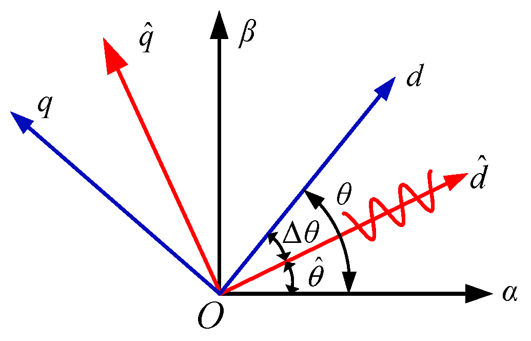
In position sensorless control systems, traditional coordinate transformation cannot be directly achieved due to the failure to obtain rotor position information through measurements. Therefore, the
axis coordinate system can be estimated, and the relationship between the estimated
coordinate system and the actual
coordinate system is shown in
Figure 1.
After coordinate transformation, the PMSM voltage equation in the three-phase coordinate system can be rewritten as the voltage equation in the synchronous rotating coordinate system
coordinate system), and its expression is as follows:
Then, the stator flux equation in this coordinate system can be expressed as follows:
The stator voltage equation obtained by inserting Formula (1) into Formula (2) is as follows:
When the frequency of the injected signal is much greater than the fundamental frequency, the voltage drop of winding resistance and the counter electromotive force of rotor rotation are much smaller than the reactance voltage of high frequency. The voltage drop of winding resistance and the counter electromotive force of the rotor can be ignored, so in the high-frequency state, the following can be obtained:
In the estimated coordinate system, the high-frequency response current expression related to rotor error is as follows:
From the above equation, it can be inferred that the high-frequency response current of the estimated
-axis is a high-frequency sinusoidal signal, and its amplitude coefficient expression is related to the position error signal. When the position error
approaches zero, the estimated position approaches the actual rotor position. Therefore, by extracting the amplitude coefficient of the high-frequency response current of the estimated
-axis and making this coefficient approach zero, the position error
approaches zero, thereby obtaining rotor position information. Therefore, the accurate acquisition of the positional error
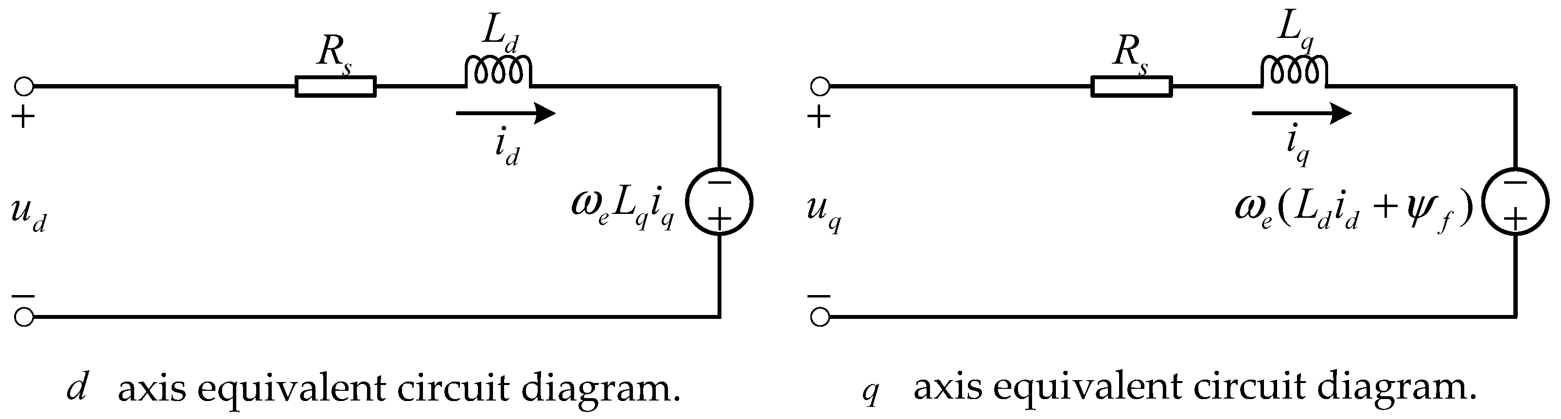
is crucial. The PMSM voltage equivalent circuit is shown in
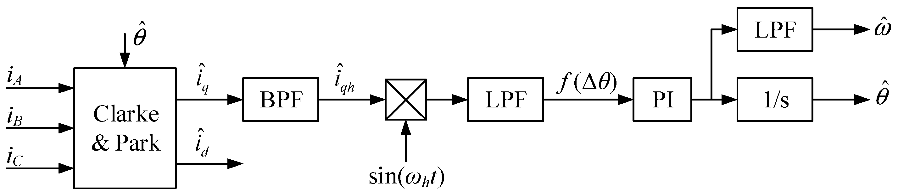
Figure 2. And, the extraction process is shown in
Figure 3. Firstly, it is necessary to use a bandpass filter to extract this component from the
-axis current, filtering out the fundamental component and high-frequency disturbance components generated by the switching signal. To extract the amplitude coefficients of high-frequency sinusoidal signals, it is necessary to multiply them by
and then use a low-pass filter to obtain the amplitude of the response high-frequency current. This amplitude is proportional to the position error, expressed as
.
in which
. When
is close to 0,
, so
can be further represented as
.
After obtaining
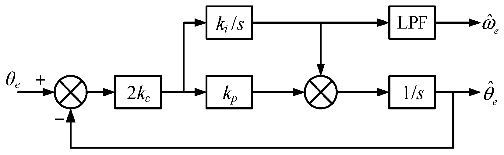
, in order to obtain the estimated position, a rotor position observer is required, using
as the input, and a phase-locked loop is used to estimate the rotor position. The schematic diagram of the phase-locked loop principle used in this article is shown in
Figure 4. This phase-locked loop consists of a PI regulator and an integrator. The PI regulator outputs the estimated speed, which is then integrated to the estimated position. When it approaches a steady state and
approaches 0, the estimated position approaches the actual rotor position.
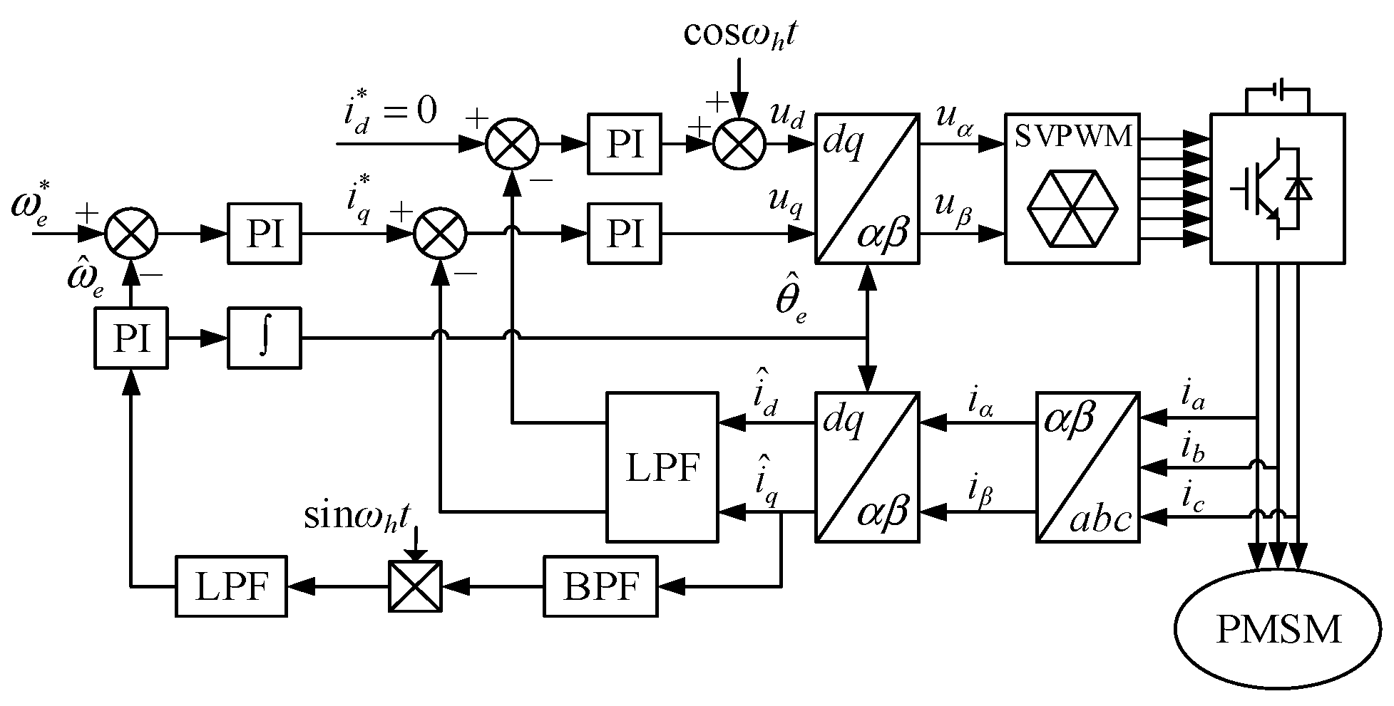
By using the pulse vibration high-frequency voltage injection method, the estimated angular position and rotational speed are obtained. By combining them with vector control, a vector control method of a permanent magnet synchronous motor based on pulse vibration high-frequency voltage injections can be obtained. The principle block diagram of permanent magnet synchronous motor vector control using position sensorless control based on the pulse vibration high-frequency voltage injection method is shown in
Figure 5. We inject the high-frequency cosine voltage signal into the estimated
-axis, process and modulate the estimated
-axis current signal through sampling, and obtain the estimated angle for coordinate transformation and the estimated position for closed-loop speed regulation.
3. Initial Position Detection
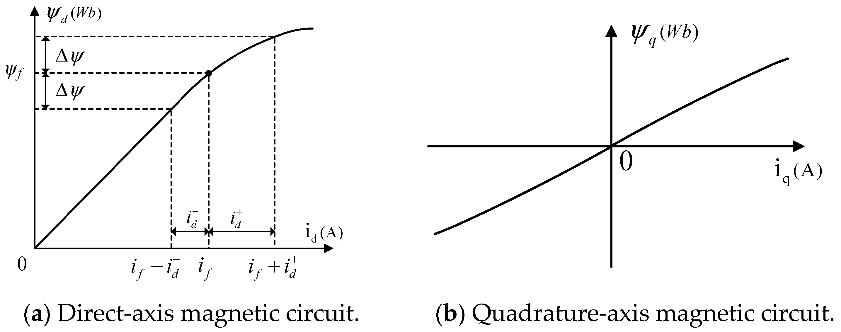
Due to the inherent problems of the pulse vibration high-frequency injection method, it is necessary to determine the polarity of the magnetic pole when applying this method for position sensorless control. The determination of magnetic polarity is usually based on the magnetic saturation characteristics of the direct-axis magnetic circuit. The magnetic circuit curves of the direct-axis magnetic circuit and the cross axis magnetic circuit are shown in
Figure 6.
The saturation characteristic of the direct-axis magnetic circuit refers to the fact that an increase in the direct-axis current will exacerbate the saturation of the magnetic circuit, leading to a decrease in the direct-axis inductance. The decrease in the direct-axis current will cause the magnetic circuit to exit the saturation state, and the direct-axis inductance will increase, as shown in
Figure 6a. Usually, in the design of the motor body, in order to maximize the output and efficiency of the motor, the working point of the direct-axis magnetic circuit is usually designed at the turning point of magnetic circuit saturation. Therefore, the direct-axis magnetic circuit judgment of permanent magnet motors is feasible and effective. The magnetization curve of the quadrature-axis magnetic circuit is an odd function, and the
-axis current does not cause quadrature-axis magnetic saturation, as shown in
Figure 6b, so the quadrature-axis magnetic circuit cannot be used for magnetic pole determination.
When using the short-pulse injection method, voltage signals of the same amplitude are injected along the positive and negative directions of the direct axis, and the voltage injection time for both is extremely short and equal. As shown in
Figure 6a, after injecting a voltage pulse, the variation in flux linkage caused by both is the same, that is, the same
. However, injecting a voltage pulse along the positive direction of the direct axis will increase the saturation of the direct-axis magnetic circuit and will reduce the saturation of the magnetic circuit and vice versa. Therefore, the two cause differences in the inductance of the direct axis, resulting in different amplitudes of the direct-axis current caused by positive and negative voltage pulses. If the magnetic pole position is correct, the current amplitude of the forward pulse increases due to the decrease in inductance, while the current amplitude of the reverse pulse is smaller than the forward current amplitude due to the almost constant inductance, which can be expressed as
.
By utilizing this characteristic, magnetic pole determinations can be achieved. After obtaining the initial position, the deviation between the estimated position and the actual position may be 0 or 180
. After injecting positive and negative pulses into the
-axis, the peak values of the
-axis current are captured, as shown in the current response waveform of the short-pulse voltage injection method in
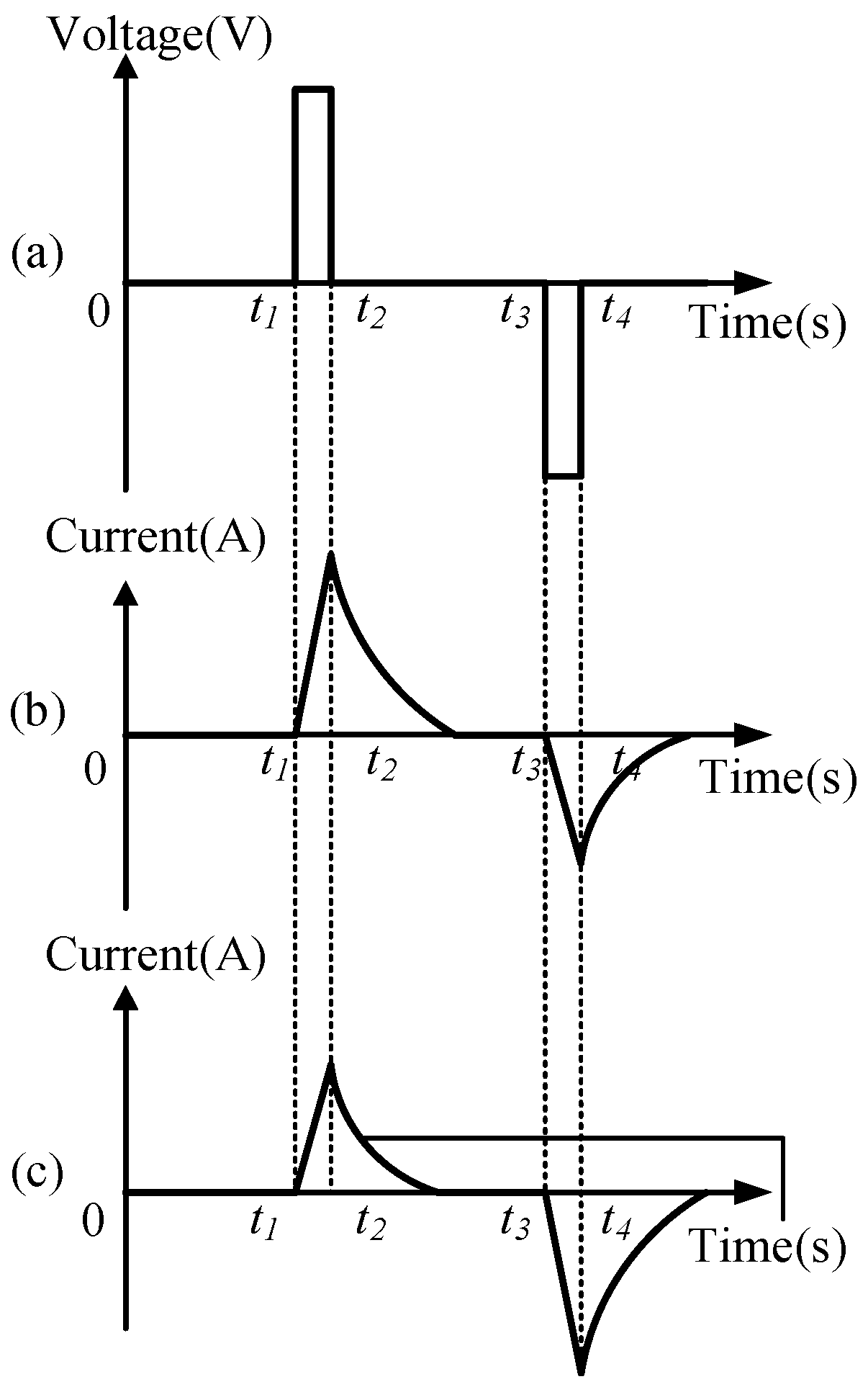
Figure 7.
Figure 7a represents the voltage pulse signal injected into the
-axis,
Figure 7b represents the current response when the voltage signal is injected into the forward magnetic pole, and
Figure 7c represents the current response when the voltage signal is injected into the reverse magnetic pole. If the amplitude of the forward current is greater than that of the reverse current, the estimated position deviation is 0. If the amplitude of the forward current is less than the amplitude of the reverse current, the estimated position deviation is 180°, and 180° compensation needs to be made in the original estimated position.
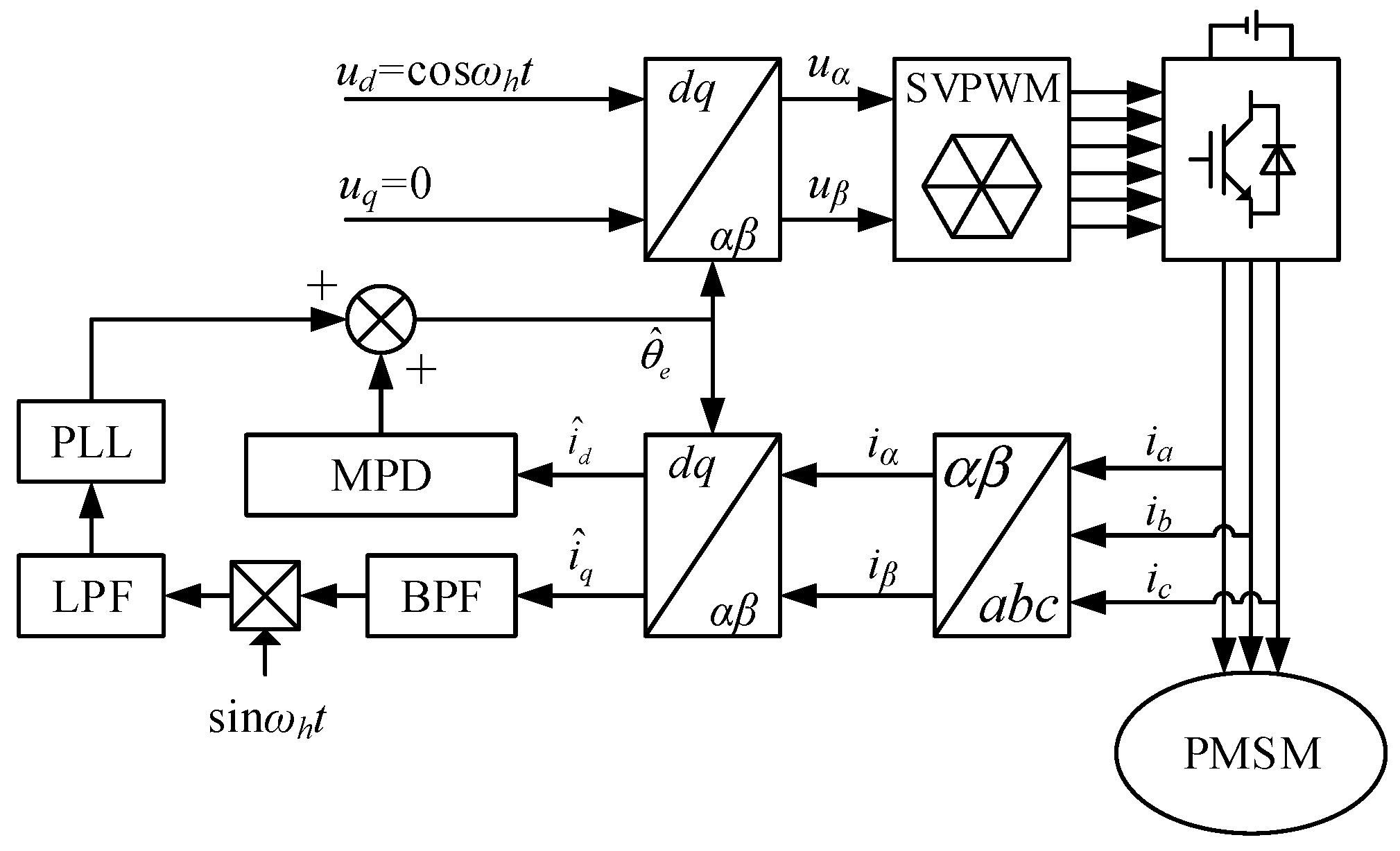
This article considers the limitations of the computing power and accuracy of the actual system hardware and adopts the short-pulse injection method. In the specific implementation, the pulse vibration high-frequency voltage injection method is first applied for the initial position calculation, and then the positive and negative short-pulse injection method is used for magnetic pole identification and judgment. Add the results of the two operations and more accurate initial position information can be obtained. The schematic diagram of the initial position calculation is shown in
Figure 8.
Due to the inherent problems of the pulse vibration high-frequency injection method, it is necessary to determine the polarity of the magnetic pole when applying this method for position sensorless control. The determination of magnetic polarity is usually based on the magnetic saturation characteristics of the direct-axis magnetic circuit. The magnetic circuit curves of the direct-axis magnetic circuit and the cross axis magnetic circuit are shown in
Figure 7.
4. Analysis of Injected High-Frequency Signals and Design of Filters
After adding phase shift φh, the phase shift of the response current also increases φh. To extract the position deviation signal, compared with before, it is only necessary to multiply by sin(ωht + φh), and the subsequent signal modulation process is the same as previously proposed. Therefore, it can be concluded that the phase shift of the injected signal has no impact on system performance.
In the process of the pulse vibration high-frequency injection method, filters need to be applied for signal extraction or noise filtering, but the application of filters inevitably affects the performance of position estimation. Therefore, such factors need to be carefully considered in the design of filters.
Generally speaking, the fundamental and second harmonics in the signal are the main components. In the subsequent selection of filter bandwidth, we select frequencies above the second and below the third to extract valuable signals and filter out other components. After passes through a bandpass filter (BPF), it will cause amplitude attenuation and phase shifts of high-frequency signals.
Below is an analysis of the bandpass filter. The transfer function expression for an ordinary second-order bandpass filter is as follows:
In the equation, is the center frequency of BPF, is the damping coefficient of BPF, which satisfies , and is the 3 dB bandwidth of BPF.
We calculate and analyze the fundamental component. The expression for the fundamental component is as follows:
After
passes through BPF, the amplitudes of components with the angular frequency (
) and (
) attenuate from b1 to
and
, respectively, with phase shifts of
and
. Since
, to simplify the calculation, the following can be considered:
After
passes through BPF, its expression is
The high-frequency current
after passing through BPF is multiplied by
and there is
After
passes through the low-pass filter (LPF), we set the cut-off frequency of BPF to
. After the signal with an angular frequency of
passes through LPF, its amplitude attenuation coefficient is
L, and the phase shift is
L; then, the expression of
after passing through LPF is as follows:
From the above equation, it can be seen that during the transient process, in the position sensorless control system based on the pulse vibration high-frequency voltage injection method, the jitter of position deviation leads to the generation of harmonics, which, together with the filter effect, further delay the signal phase and have an adverse impact on position estimation.
The function of a bandpass filter is to extract the corresponding high-frequency response signal, and its bandwidth selection has a significant impact on the performance of the system. If the selected bandwidth is too wide, the filtered signal will have increased noise component, except the high-frequency signal. However, if the bandwidth is so narrow that the bandwidth , it will cause serious signal attenuation and cannot extract the high-frequency component signal of the response current. If the maximum speed of a permanent magnet synchronous motor operating in the low-speed range is , then the selected bandwidth is generally 2–3 times .
The main parameter of a low-pass filter is its low-pass cut-off frequency, which needs to be filtered out as much as possible from the high-frequency component of . Therefore, considering the frequency of the injected high-frequency signal, the low-pass cut-off frequency should not be too low to avoid causing severe phase delay. Generally, 1/10 of the frequency of the injected high-frequency signal is chosen to filter out high-frequency signals while ensuring a high bandwidth.
Digital filters are mainly divided into finite impulse response (FIR) filters and infinite impulse response (IIR) filters, and their specific forms are as follows:
These two types of filters have their own advantages and disadvantages. From the transfer function of the FIR filter, it can be seen that FIR has good stability and a strict linear relationship in phase. However, to achieve the same filtering effect as the IIR filter, the order of the FIR filter should be much higher than that of the IIR filter. The higher the order, the larger the n, which means the greater the computational complexity. The order of IIR filters is relatively low, but there are stability issues. Due to the high computational complexity of the position sensorless control method, considering the limitations of the hardware itself, an IIR filter is selected. In terms of order selection, a fourth order is selected as for the bandpass filter and a second order for the low-pass filter.
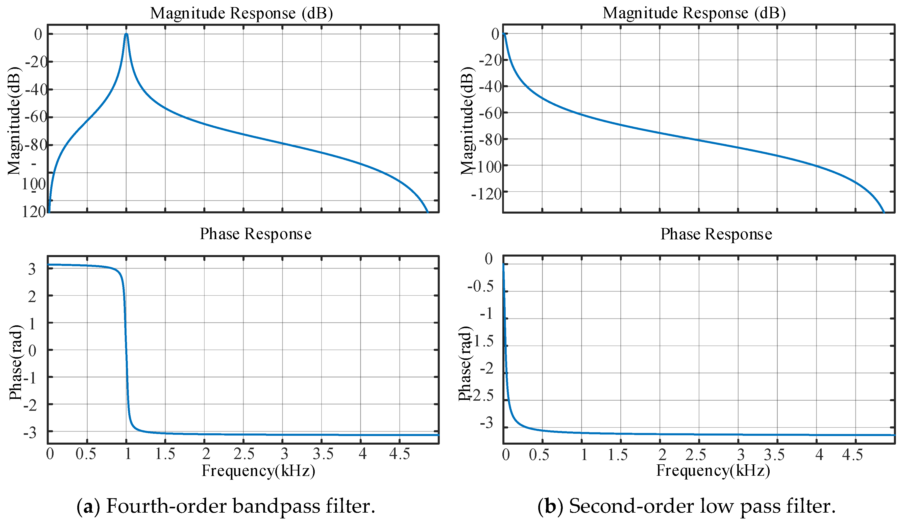
The frequency of the injected high-frequency signal is 1000 Hz, and the frequency of fundamental waves of motor operation is 10 Hz. The bandpass filter type is selected as a fourth order IIR filter, with a center frequency of 1000 Hz, a bandwidth of 40 Hz, and a sampling frequency of 10 kHz. The BPF digital filter expression is obtained as follows:
In terms of the type of the low-pass filter, a second-order IIR filter is selected, with a cut-off frequency of 1/10 of the injected high-frequency, i.e., 100 Hz. The resulting LPF digital filter expression is as follows:
Figure 9 shows the Bode plot of the designed filter. The Bode plot shows that the bandwidth of the bandpass filter is 40 Hz, and the maximum phase shift within the bandwidth is 1.57 rad. The bandwidth of the low-pass filter is 100 Hz, and the phase shift at the cut-off frequency is 1.57 rad.
5. Simulation and Experimental Verification
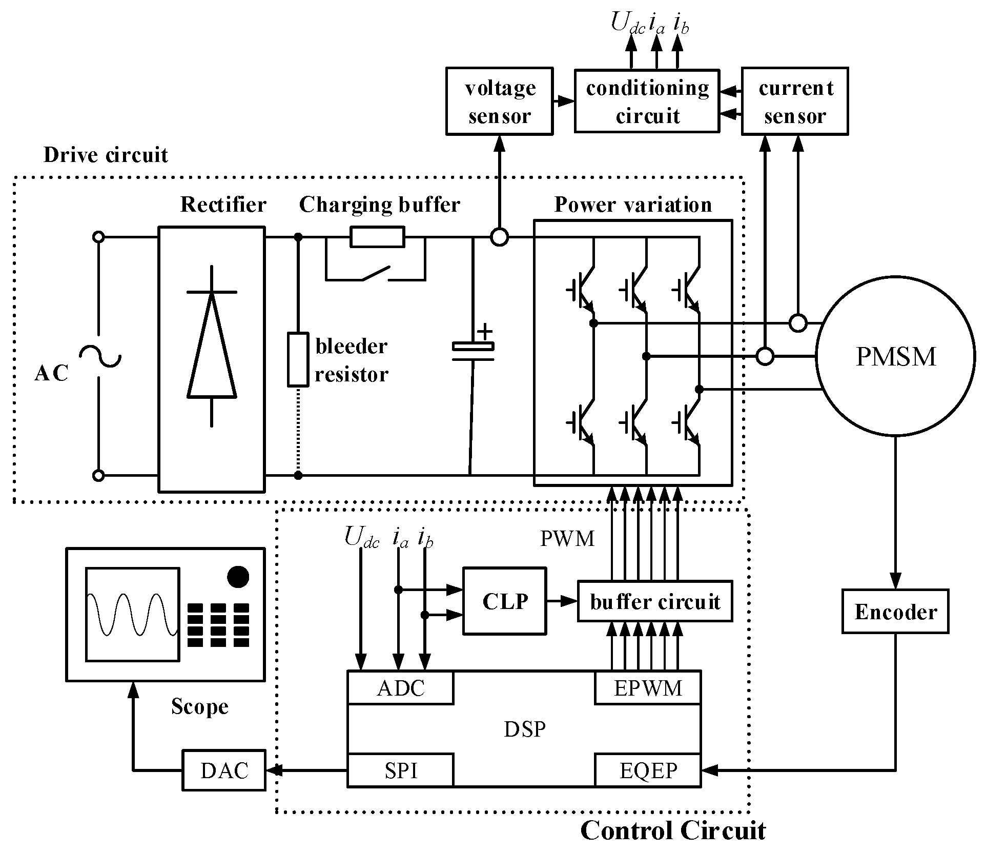
Based on the theoretical analysis and system design mentioned above, a hardware system of the experimental platform is built. The system is mainly divided into three parts: control circuit, driving circuit, and permanent magnet synchronous motor, as shown in
Figure 10.
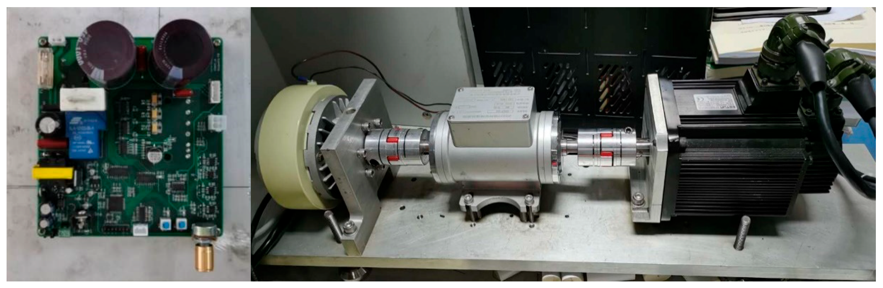
Based on the above hardware circuit design, a hardware platform is designed, as shown in
Figure 11.
Simulation and experimental verification mainly focus on three parts: vector control of the pulse vibration high-frequency injection system, initial magnetic pole determination, and the impact of injection signals on position tracking performance. The motor parameters are shown in
Table 1.
5.1. Simulation and Experiment of Pulse Vibration High-Frequency Injection Applied in Vector Control System
According to the motor parameters given in
Table 1, the current loop PI parameters are designed as follows:
-axis current loop
,
and
-axis current loop
. We ensure that the rotor position error is within 20°, and the PI parameter of the designed speed ring is
.
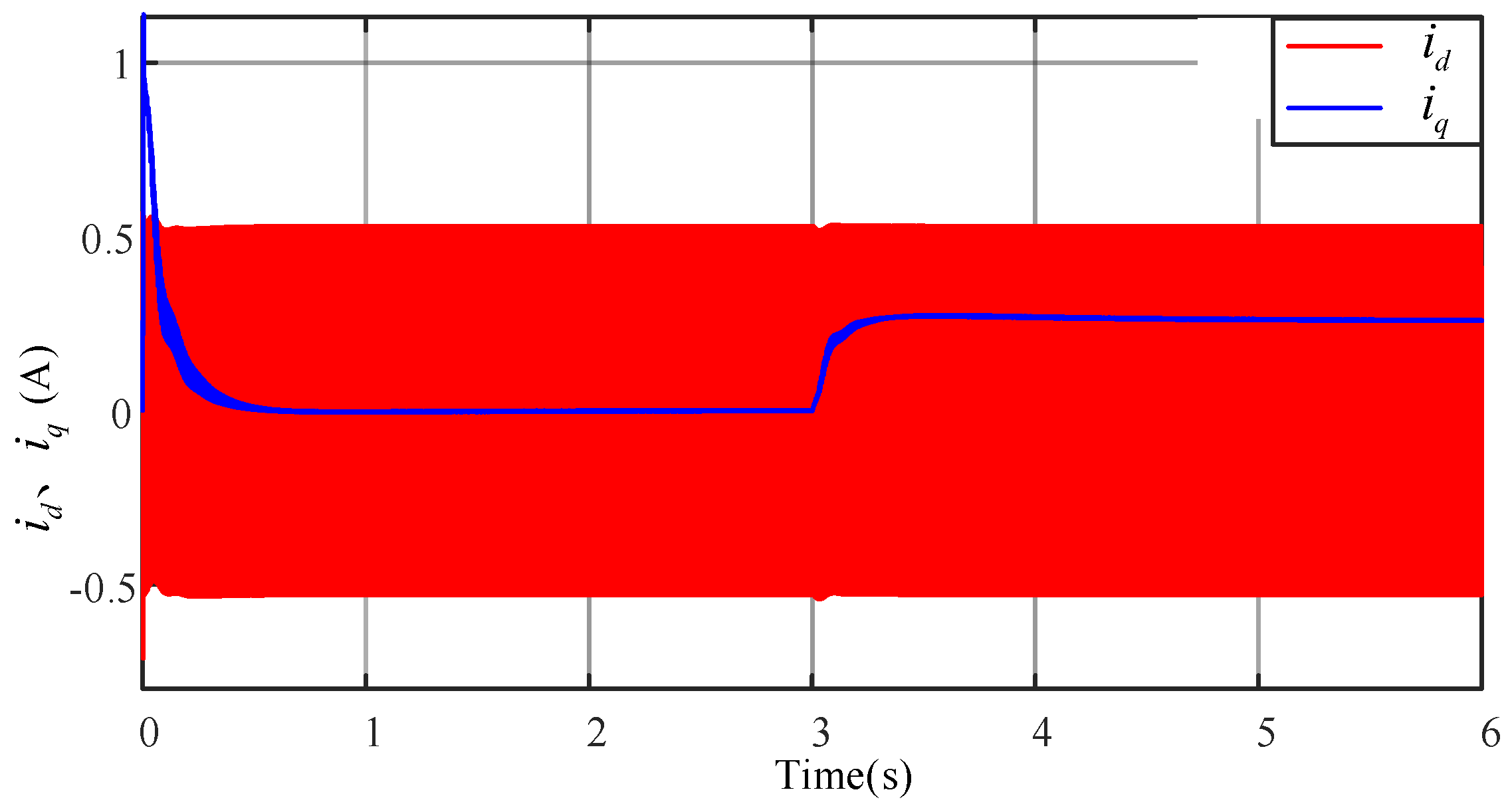
The simulation results are shown in
Figure 12 and
Figure 13.
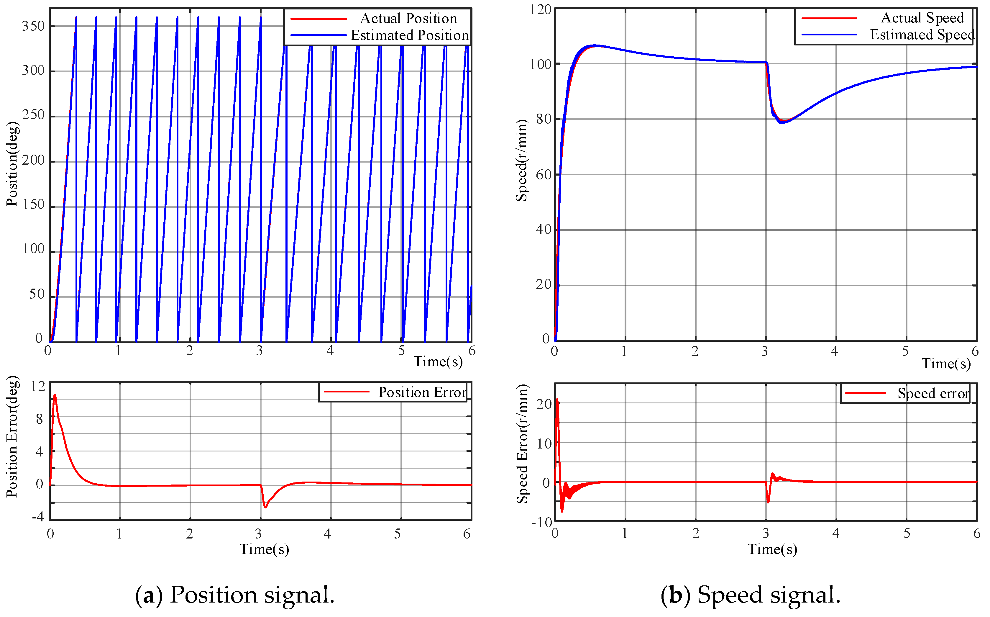
Figure 12a shows the position waveform,
Figure 12b shows the speed waveform, and
Figure 13 shows the
-axis current waveform after low-pass filtering. The motor is initially started with no load, and a step load of 0.5 N. m is given at the time of 3 s. From the waveform, it can be seen that using the pulse vibration high-frequency injection method, the estimated position and speed information can accurately track the actual position and speed, with a maximum position estimation error of about 10°. Even with a sudden increase in load, it can still achieve better tracking. The estimated value always has a certain delay compared to the actual value but can converge to the actual position and speed without error after entering a steady state.
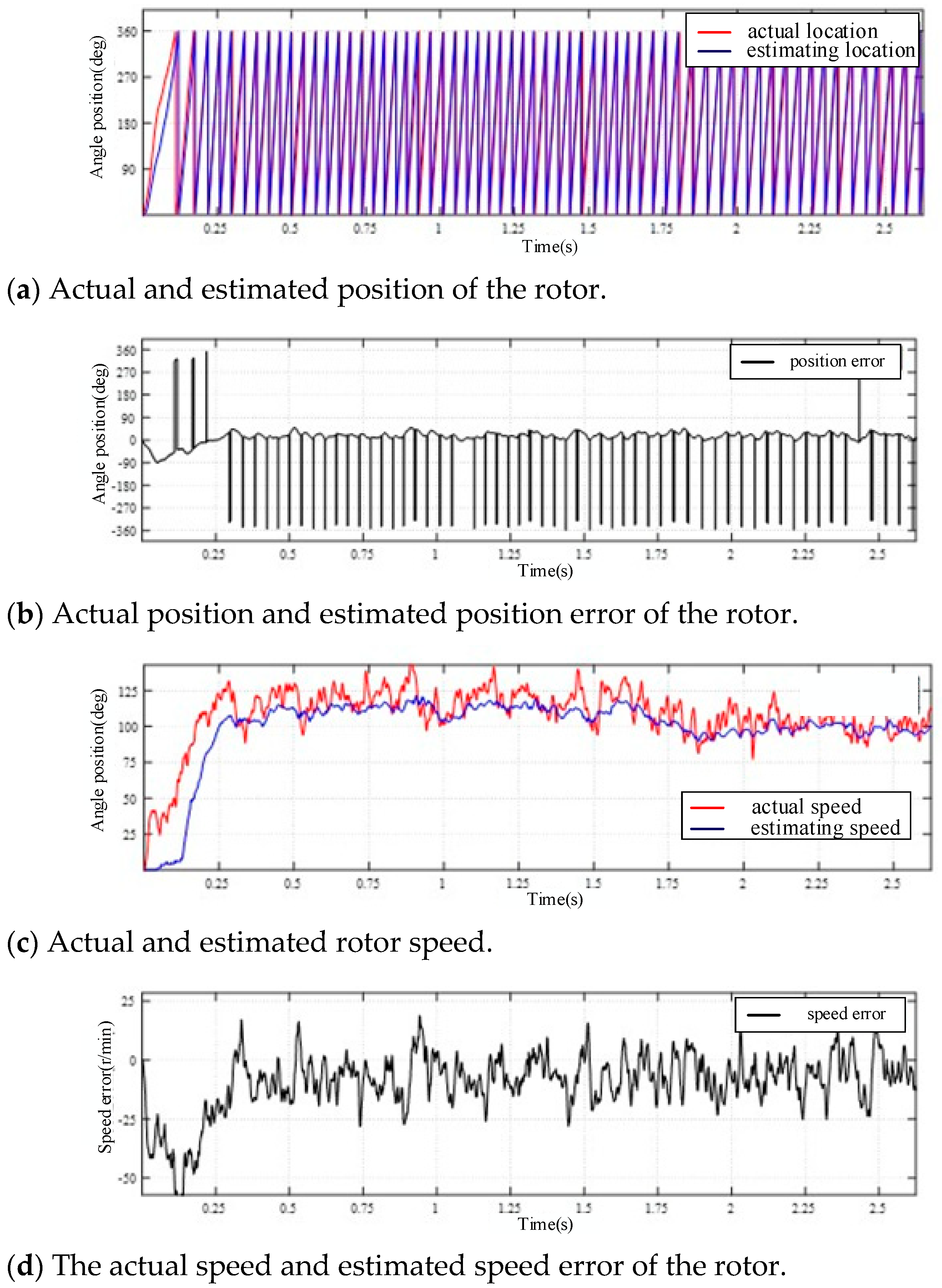
Subsequently, based on the above simulation parameters, a sensorless permanent magnet synchronous motor vector control experiment is conducted using the pulse vibration high-frequency injection method. The parameters for injecting high-frequency signals are selected as follows: the amplitude of the high-frequency signal is 20 V, the frequency is 500 Hz, the given speed is 100 r/min, and a load is applied to the motor at the time of 1.75 s. We drag the initial position of the motor rotor to an electrical angle position of 0° and observe the position tracking performance and speed estimation performance. The experimental results are shown in
Figure 14. The experimental waveform shows that by applying the closed-loop vector control based on the pulse vibration high-frequency injection method, the estimated position and speed can effectively track the actual position and speed.
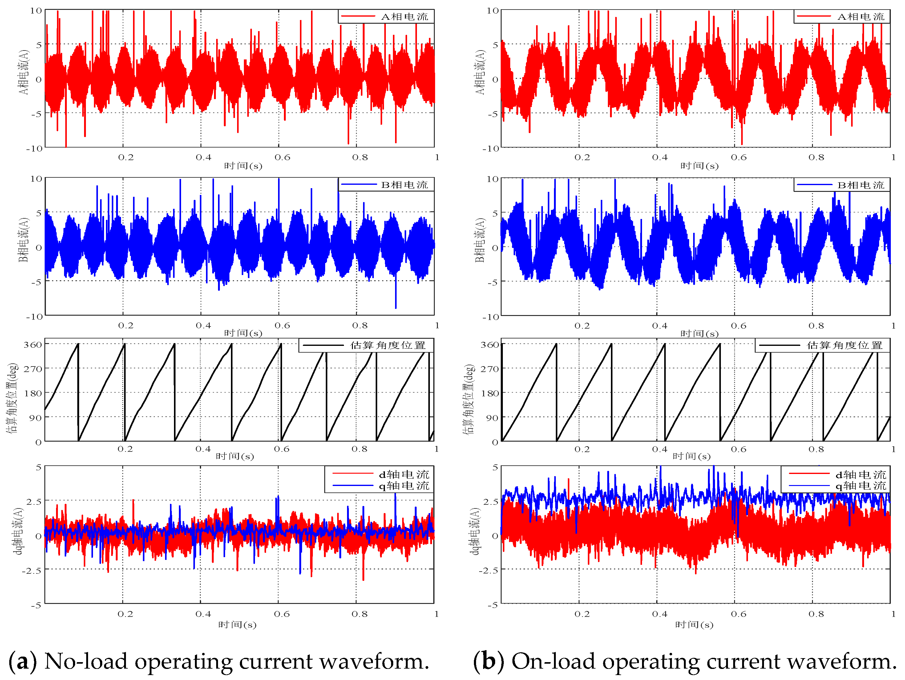
Figure 15 shows the current waveform during the low-speed stable operation of the motor. After starting the motor using the pulse vibration high-frequency injection method and stabilizing the operation, we select any 1 s interval to observe the current waveform during the stable operation process. Among them,
Figure 15a represents the no-load current waveform, and
Figure 15b represents the loaded current waveform. From the figure, it can be concluded that as for the position sensorless control using the pulse vibration high-frequency injection method, the current value of the system increases correspondingly when there is a load. Whether running with or without a load, the estimated position and speed of the rotor can better follow its actual position and speed. Position sensorless control can meet the accuracy requirements of on-board motor drive control systems.
5.2. Simulation and Experiment of Initial Position Identification
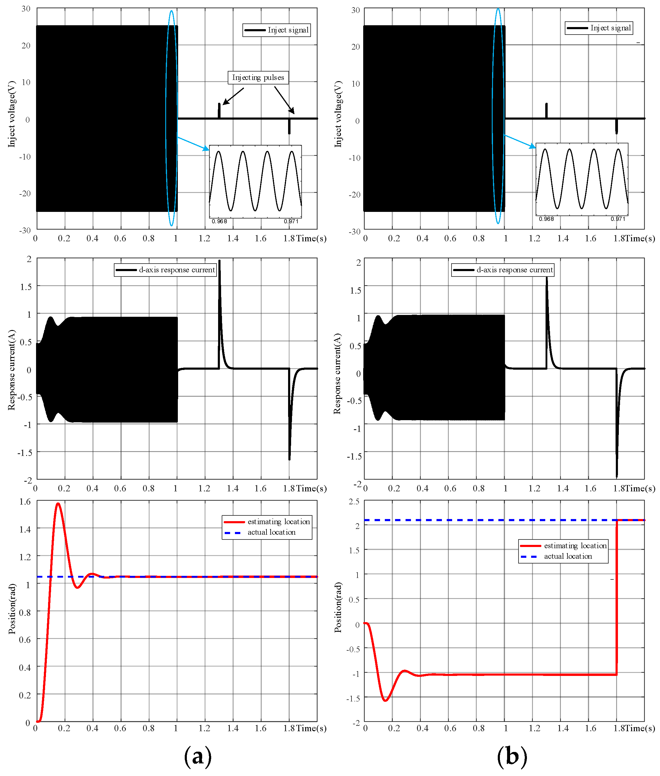
Based on the mathematical model for the initial position identification mentioned above, a simulation is built, and the operating results are shown in
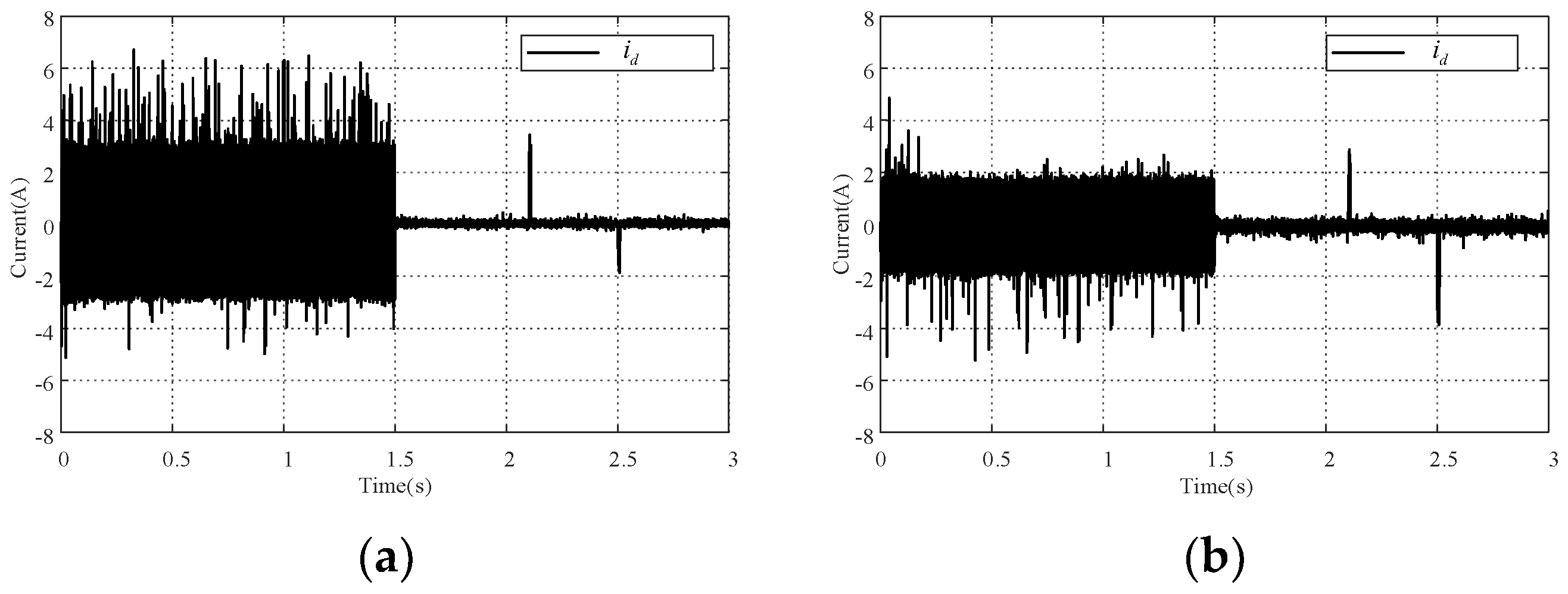
Figure 16. Among them,
Figure 16a represents the simulation result with the initial position set at 60°, while
Figure 16b represents the simulation result with the initial position set at 120°. From top to bottom, the results of
-axis injection voltage signal,
-axis response current signal, and position estimation are presented. The injected voltage signal is a cosine signal with an amplitude of 25 V and a frequency of 1000 Hz. The injected positive and negative short pulses are both voltage pulses with an amplitude of 4 V and a width of 3 ms.
Using DSP as the main control chip, the carrier frequency of PWM is 10 kHz, which is also the sampling frequency of the current. The injected high-frequency signal has an amplitude of 20 V and a frequency of 500 Hz. The rotor is positioned at 60° and 120° positions for testing, including initial positioning and pole identification. In order to verify the correctness of the position, an incremental encoder is added to provide feedback on the actual position information.
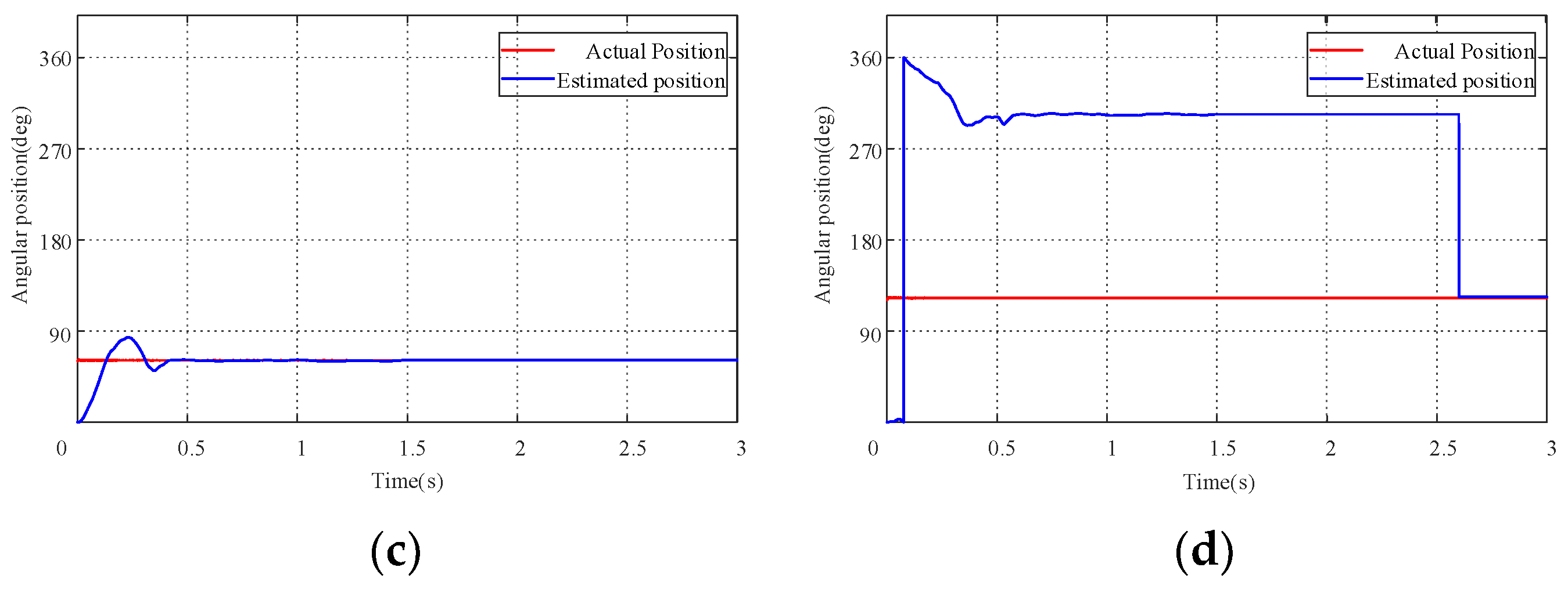
Figure 17 shows the experimental waveform of the initial position, where
Figure 17a,b represent the high-frequency response current waveforms with initial positions at 60° and 120°. During the time period of 0–1.5 s, the estimated position of the injected high-frequency signal varies in response to the presence of the direct-axis magnetic saturation effect, which is due to the difference in high-frequency current amplitude caused by different inductance values. At 1.5 s–2.6 s, positive and negative short pulses are injected into the
-axis, and the response current waveform is observed. From the graph, it can be seen that the current response and simulation analysis are consistent. The experimental results show that the positive and negative short-pulse injection method is effective.
Figure 17c,d represent position estimations with initial positions at 60° and 120°.
Based on the waveform obtained above, a pulse vibration cosine signal is injected at the initial stage, and the initial position is estimated using the pulse vibration high-frequency injection method. The converged position may deviate by 180° from the actual rotor electrical angle position. Using the short-pulse injection method for magnetic pole determination, a voltage pulse is injected into the
-axis to obtain the response
-axis current pulse. By comparing the absolute values of the peak values of positive and negative current pulses, the magnetic pole information is obtained. When the peak value of the negative current pulse is greater than that of the positive current pulse, position compensation is performed. The simulation waveform in
Figure 17 shows that this method can accurately obtain the initial position of the rotor.
The experimental results show that during the initial stage when the motor rotor is stationary, the estimated position information can accurately track the actual position using the high-frequency injection method and magnetic pole judgment.
5.3. Experiment on Effects of Different Injected Signals’ Amplitudes and Phases on Position Tracking Performance
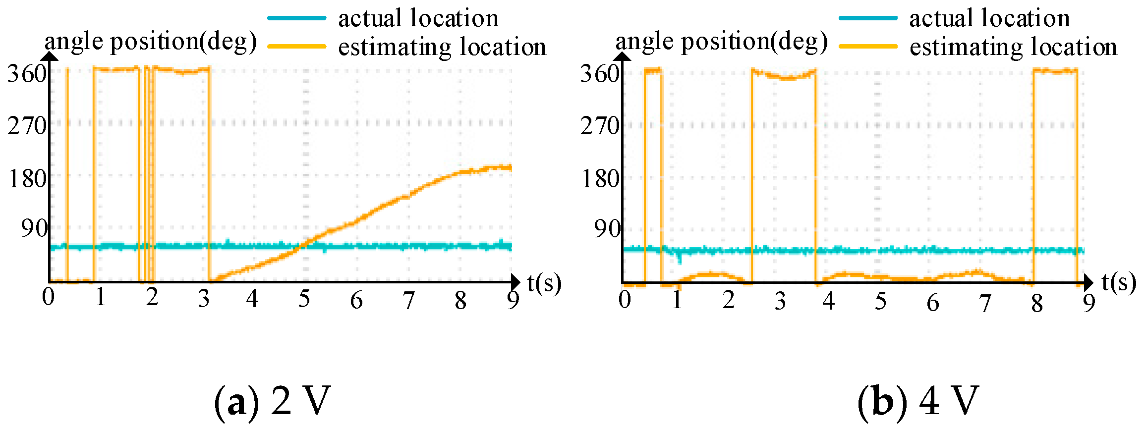
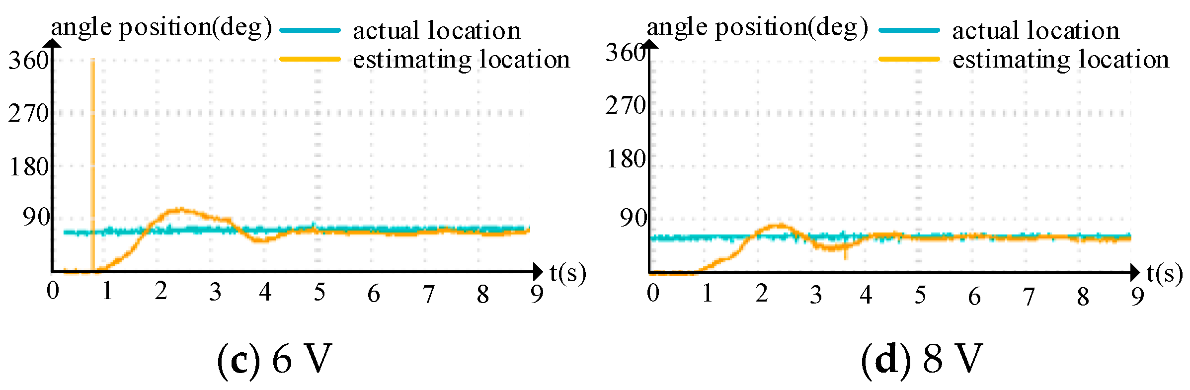
Figure 18 shows the comparison of position tracking performances under different injection amplitudes under the condition of an injection frequency of 500 Hz. Similarly, position tracking is performed separately under the condition of a stationary rotor.
Figure 18a–d are injection amplitudes of 2 V, 4 V, 6 V, and 8 V, respectively. It is noted that the phase of the injected signal does not affect system performance. Low-pass and high-pass filters are employed for extracting position error information. However, setting unreasonable bandwidths for the filters can deteriorate estimation performance or even lead to estimation failure. This chapter proposes principles for designing filter parameters and utilizes MATLAB’s FDATOOL tool to design the required filters. Upon validation, the designed filters meet the system requirements, effectively reducing noise interference caused by high-frequency PWM injections, thereby enhancing motor control precision and system robustness.
This approach offers the advantage of effectively mitigating noise interference caused by high-frequency PWM injections through the judicious design of filter parameters, thereby enhancing motor control precision and system robustness.
The experimental results indicate that position tracking fails when the injected amplitude is too low. This is because the high-frequency response current is small, the signal-to-noise ratio is small, and the filter cannot extract the required signal, which cannot modulate the signal to calculate the actual rotor position. When the injection amplitude increases to 6 V, the signal-to-noise ratio increases and the signal can be extracted. The higher the injected amplitude, the better the position tracking performance.
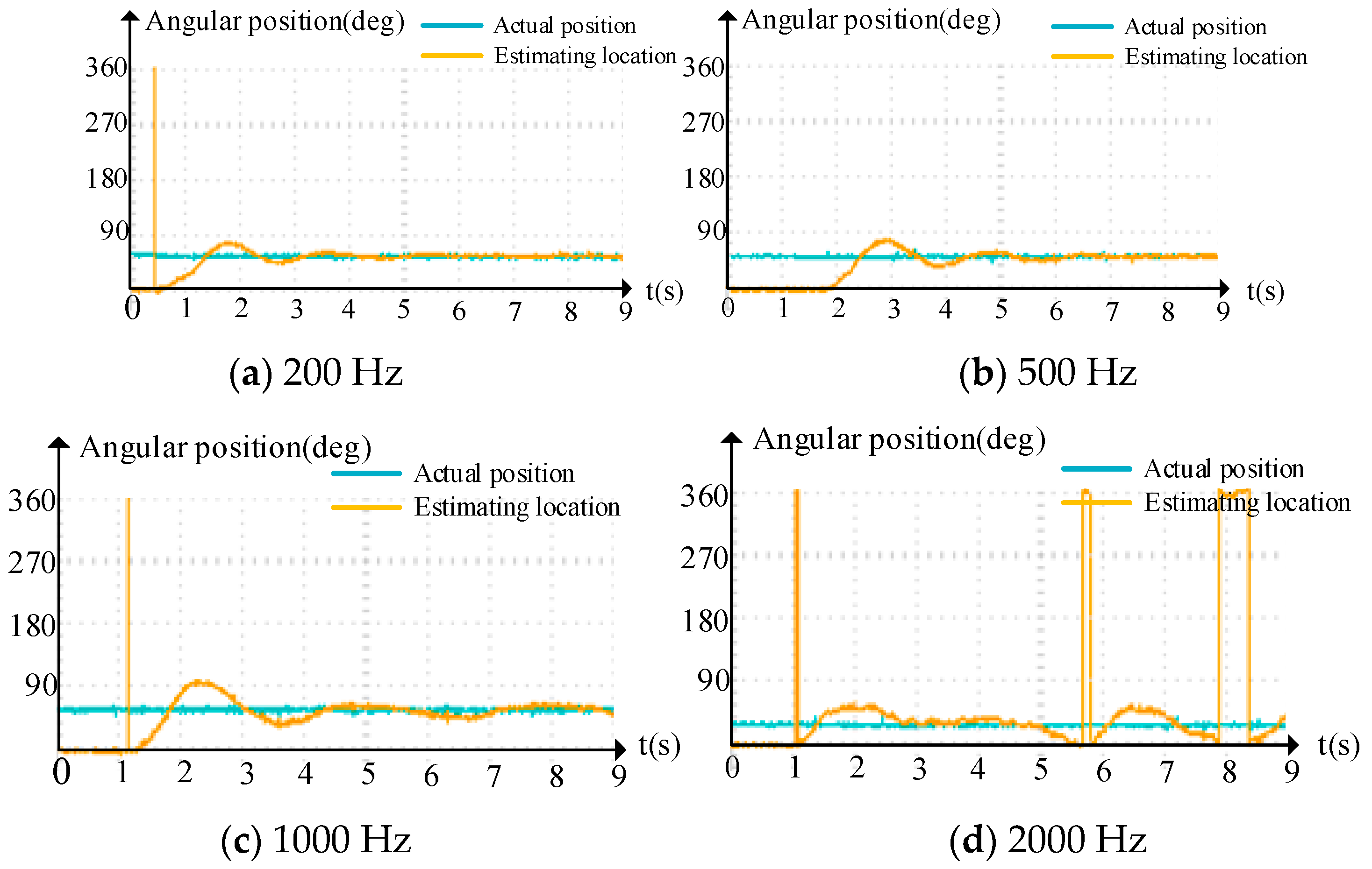
Figure 19 illustrates the position tracking characteristics at the injected amplitudes of 20 V and injected frequencies of 200 Hz, 500 Hz, 1000 Hz, and 2000 Hz, respectively. We perform position tracking separately under stationary rotor conditions. The experimental results show that when the frequency is low, the position can be accurately estimated, and the lower the frequency, the faster the estimation speed and higher the accuracy. When the injected frequency is large and close to the carrier frequency of PWM, as shown in
Figure 18d, after injecting a 2000 Hz high-frequency signal, accurate position tracking cannot be achieved, indicating that an excessively high frequency will lead to a poor estimation performance.
The reliability of the aforementioned conclusions has been fully verified through a series of simulation experiments. The position sensorless control system based on the pulse vibration high-frequency injection method has good position estimation and response performance under stable working conditions, as well as the sudden acceleration of speed and load. By using initial position estimations combined with magnetic pole judgment, the inherent error problem of high-frequency pulse injections can be avoided. For high-frequency injected signals, the higher the amplitude, the better the position tracking performance without increased loss. The injected frequency needs to be much higher than the fundamental frequency of the motor, but if the injected frequency is too high and approaches the PWM carrier frequency, the position estimation performance will deteriorate.
6. Discussion
The third chapter focuses on the analysis and research of the phase-locked loop (PLL) observer, addressing the nonlinearity of the position error signal inputted into the PLL, which may result in an estimated position deviating by 180° from the actual position. A method utilizing the saturation characteristics of the straight-axis magnetic circuit is proposed for magnetic pole determination. A comparison of two methods for pole determination is presented, highlighting the advantages and disadvantages, ultimately adopting the short-pulse voltage injection method due to current constraints. Given the limitations of traditional vector control PI parameter design for sensorless vector control, a methodology for designing velocity loop PI parameters using pulse injection at high frequencies is introduced in this chapter. Simulation analyses using MATLAB/Simulink validate the effectiveness of the theoretical analyses.
The fourth chapter primarily investigates the influence of injection parameters on system performance and the impact of filters on the system. The effects of injection parameters, including amplitude, frequency, and phase, are studied. It is observed that an insufficient amplitude may lead to inaccurate tracking of the actual position due to current noise interference, while excessive amplitude increases system losses. In the process of implementing computer algorithms, discrete data processing imposes limitations on the selection of injection frequency. The analysis suggests that the chosen injection frequency should be significantly higher than the motor fundamental frequency while avoiding proximity to the PWM carrier frequency. The chapter recommends setting the injection frequency to be 1/20 to 1/10 of the PWM carrier frequency. The phase of the injection signal has no impact on system performance. Furthermore, principles for designing filter parameters are proposed, and using MATLAB’s FDATOOL tool, filters that meet system requirements are designed and validated.
Overall, these chapters encompass analyses on the nonlinearity of PLL observers, the selection of pole determination methods, the impact of injection parameters on system performance, and filter design principles. The simulation results corroborate the efficacy of the theoretical analyses.
7. Conclusions
This article conducts research on the starting and low-speed operation of permanent magnet synchronous motors using position sensorless control, analyzes the operating principle of the pulse vibration high-frequency voltage injection method for permanent magnet synchronous motors, and adopts the short-pulse injection method for magnetic pole assessments to address the problem of the initial position estimation deviation of 180°. In response to the problem that the hysteresis of the observer will lead to the failure of estimating the position tracking of the actual position, the impact of different high-frequency signal injection parameters on the performance of position estimation is analyzed. The analysis shows that when selecting the signal amplitude, affected by current noise errors, if the injected amplitude is too small, the estimated position cannot accurately track the actual position. If the injection’s amplitude is too large, the system loss will increase. The injection’s amplitude range proposed in this article meets the following requirements: the minimum amplitude is , and the maximum amplitude is 1/10 of the rated voltage. When selecting the signal frequency, the injected frequency should be much greater than the motor’s fundamental frequency and cannot be close to the carrier frequency of PWM. The phase of the signal has no impact on system performance, and simulation and experiments have verified the effectiveness of the theoretical analysis. At the same time, the impact of filter parameters on system performance is analyzed, and a universal design method for filter parameters is proposed. The feasibility of the design method is confirmed through the simulation of the designed filter. The proposed method enables the stable start and operation of the position sensor-less permanent magnet synchronous motor, resulting in reduced motor production costs, space compression, and improved system stability under harsh working conditions.
Due to the limitation of time and other factors, there are still some works in this subject that need to be further studied, and the follow-up work can be carried out acknowledging the following aspects:
- (1)
In practical application, the influence of the PWM dead zone on system performance is a factor that cannot be ignored, and the influence of the dead zone on system performance can be further studied;
- (2)
Under heavy load conditions, the increase in current leads to a magnetic saturation effect, and the influence of injection parameters on system performance is worth studying;
- (3)
Under fast variable loads, once the position observer fails to track the actual position, the position deviation of the π electric angle occurs, and how to detect and correct this should be studied.


