Article

Study of an Electric Vehicle Charging Strategy Considering Split-Phase Voltage Quality

Linfen Power Supply Company, State Grid Electric Power Company, Linfen 41000, China
*
Author to whom correspondence should be addressed.
World Electr. Veh. J. 2024, 15(7), 315; https://doi.org/10.3390/wevj15070315
Submission received: 27 June 2024 / Revised: 14 July 2024 / Accepted: 17 July 2024 / Published: 18 July 2024
(This article belongs to the Special Issue Data Exchange between Vehicle and Power System for Optimal Charging)

Abstract

:
Slow-charging electric vehicle (EV) loads are single-phase loads in the power distribution network (PDN). The random access of these EVs to the network brings to the forefront the split-phase voltage quality issues. Therefore, a two-layer EV charging strategy considering split-phase voltage quality is proposed in this paper. Issues with voltage unbalance (VU), split-phase voltage deviation (VD), and split-phase voltage harmonics (VHs) are included in the optimization objective model. An upgraded version of the multi-objective non-dominated sorting genetic algorithm (NSGA-II) is used in the inner layer of the model and to pass the generated EV phase selection scheme to the outer layer. The outer layer consists of a split-phase harmonic current algorithm based on the forward–backward generation method, and feeds the voltage quality calculation results to the inner layer. After several iterations, the optimal EV phase selection scheme can be obtained when the inner layer algorithm satisfies the convergence condition. The results gained for the example indicate that the suggested EV charging approach can effectively handle the PDN’s split-phase voltage quality. Furthermore, it enhances the energy efficiency of PDN operations and promotes further energy consumption.

1. Introduction

The proposal of the “low-carbon target” has promoted the rapid development of electric vehicles (EVs) [1]. As the number of EVs increases, voltage quality problems such as voltage deviation (VD) and voltage harmonics (VHs) [2] are becoming more and more prominent in the distribution network (PDN) [3]. In particular, the random access of single-phase slow-charging EVs to the network will lead to three-phase voltage unbalance (VU) problems [4], increase network losses, affect the life of grid equipment, and even cause the distribution terminal equipment to trip [5]. Aimed towards the split-phase voltage quality problem caused by single-phase EV charging, the study of EV charging strategy is crucial to improve the operational reliability and voltage quality of PDNs.
Because EVs are being charged at the same time, the PDN may struggle to keep up with the electricity demand, and even reduce grid security [6]. Existing research into optimization strategies for EV access to the grid focuses on orderly charging. Reference [7] explores the potential of peak shaving and valley filling for EVs, and that load peak-to-valley differentials can be effectively reduced through reasonable tariff guidance. Reference [8] takes into account the grid load fluctuation and user travel demand, and guides EV charging in the valley time through time-sharing tariffs for sub-regions. Reference [9] has shown how the coordinated dispatch of wind power and EVs minimized load volatility. Reference [10] proposes a dynamic time-sharing pricing method to optimize EV loads by considering the willingness of the user side to participate in grid-side peaking. Although the above studies can reduce the peak-to-valley difference in EV grid connection as much as possible through sequential charging, the current calculation is based on the assumption that the three-phase parameters of the PDN are the same, and connect the EV loads to the three phases equally. If slow-charging EVs are connected to the grid in a single-phase manner, it will exacerbate the grid unbalance and harmonic problems, and the voltage quality problems caused by EV access cannot be improved by the orderly charging method.
Existing voltage quality problems caused by single-phase grid-connected EVs are mostly solved by access to control devices. Reference [11] uses sag controllers to reduce the unbalanced component, but this may cause voltage oscillations. Reference [12] proposed a control algorithm based on adaptive notch filters (ANFs), which provide current harmonic compensation and reactive power support to reduce harmonics generated by EV access. Reference [13] reduces the VU in the PDN by switching the three-phase residential loads. However, due to the frequent load fluctuations of EVs, the use of phase-change switching will lead to frequent commutation switching actions, raising the risk of commutation failures during the phase switching process and increasing phase change losses [14]. A summary of past publications related to the proposed methodology in [7,8,9,10,11,12,13,14] is summarized in Table 1. Furthermore, even though adding more equipment can somewhat mitigate one of the indicators of VU, VD or VHs brought on by EVs connected to the PDN, this also raises the network’s complexity and operational expenses.
There is an unbalance issue with the PDN operation due to the asymmetry of the load of each phase. If EV access is not controlled, it may worsen this unbalance as well as other voltage quality issues. However, if the asymmetrical access of EVs is fully utilized through reasonable control, and access is provided to a smaller number of EV loads in phases with higher base loads, this disadvantage will be turned into an advantage, and the benefits of flexible access will be fully utilized as an effective means of regulating grid unbalance.
In summary, this paper proposes an EV charging strategy taking into account the split-phase voltage quality. By directly controlling the charging phase of EVs, it will reduce the three-phase VU, the maximum split-phase VD, and the VH distortion rate at all of the PDN nodes during the day as much as possible. By setting the weight coefficients of the multi-objective function according to the subordination function, and designing a two-layer algorithm to solve the problem, the outer layer creates a three-phase forward and backward generation split-phase harmonic current model to solve the node split-phase voltage, and the inner layer solves the EV split-phase charging model by NSGA-II to control the split-phase access of EVs. The findings demonstrate that, when EVs are linked to the PDN on a broad scale, the suggested EV charging approach that takes split-phase voltage quality into account may successfully improve the voltage quality of the network and guarantee the network’s safe and dependable functioning.

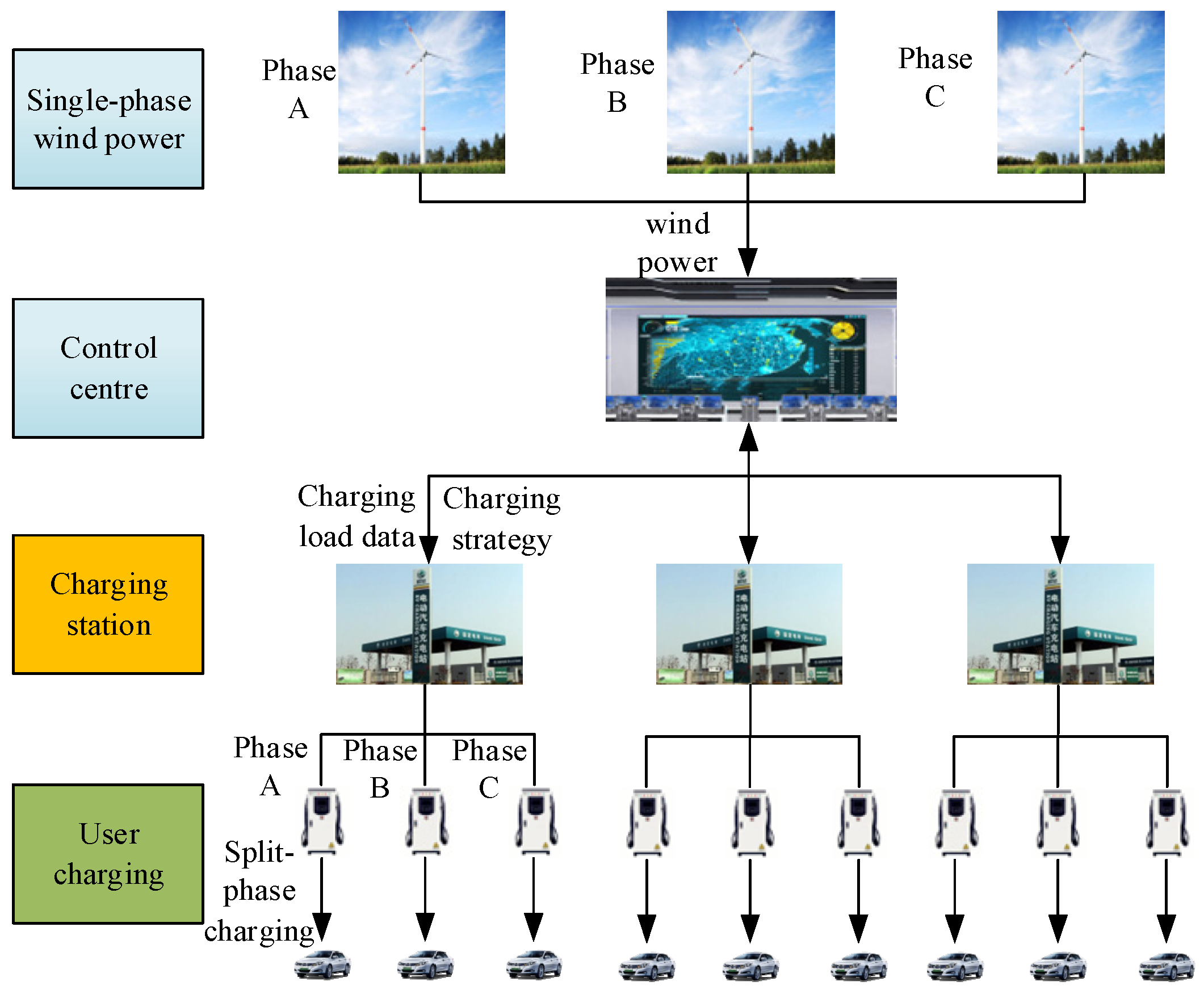
2. Electric Vehicle Charging Strategy

As the number of EVs expands, single-phase charging becomes more random. When single-phase loads are accessed, the system unbalance will worsen compared to the initial PDN with unbalanced base loads. In parallel, the distribution grid side gradually increases single-phase access to dispersed wind power. Because wind power output is strongest at night and lowest during the day, it has a strong complementarity with the large-scale single-phase access to private cars at night. When determining the EV charging strategy, we must consider the split-phase access and complementary characteristics of EVs and wind power, and connect more EV loads to the network during the split-phase of the peak wind power output, which will help us to meet the charging demand while balancing the wind power output. In addition to taking into account unbalance in the grid, harmonics from wind power and EVs will be introduced into the system through power electronic converters. The charging strategy should also consider the harmonics injected into each phase so that each phase harmonic is not exceeded. Because of the PDN’s heavy load, a low node voltage will occur when it is connected to an EV load. It is evident that the PDN would experience issues with VU, VD, and VHs as a result of EVs and dispersed access of wind generation to the grid. This study investigates the method of EV charging with the aim of improving the node voltage quality of the PDN considering the uncontrollable and optimal utilization of scattered wind power generation. By controlling the phase of single-phase EV load access, it not only solves the voltage quality problem caused by EV and wind power access, but also solves the unbalance problem caused by PDN base load.
Figure 1 depicts the split-phase charging procedure for EVs. The power system control center receives the total charging load booked from each charging station, and then makes use of these data to create a charging model for EVs in separate phases based on the cumulative charging demands of every phase and the generation of wind power. In order to finalize the EV charging phase selection, the power system control center also sends the charging plan to each station. And EV users should charge their vehicles in line with the intended charging loads assigned by the charging scheme.

3. EV Charging Strategy Accounting for Voltage Quality

Solving voltage quality issues experienced by the bulk of end-use power consumers is difficult because of the decentralized and huge PDN user base, which leads to load unbalance issues in the PDN itself [15]. Voltage quality issues in the power system seem to be made worse by EVs’ single-phase disorderly access. Consequently, determining the proper voltage quality index to serve as the objective function for EV access and deriving the split-phase charging strategy for EVs in this paper effectively mitigates the voltage quality issue caused by EVs connecting to the grid randomly and enhances the power grid’s operational stability.

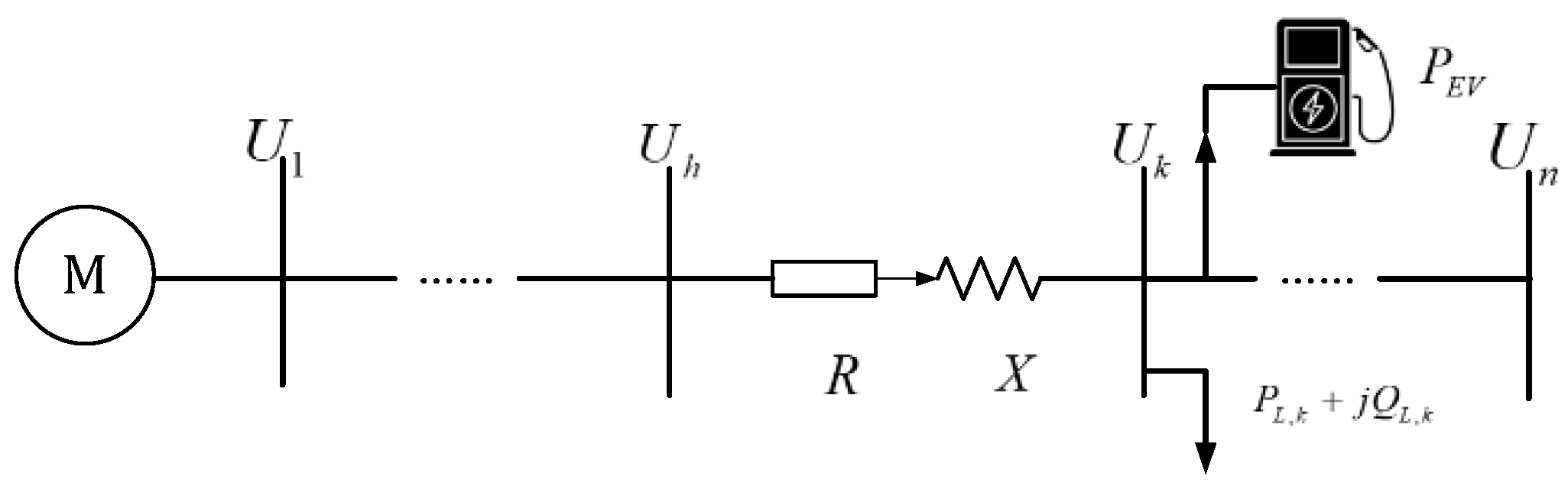
3.1. Voltage Quality Analysis

Voltage quality contains several indicators such as three-phase unbalance [16], and it is of great significance to select appropriate indicators to measure the impact of EVs on the PDN.
The EVs’ access to the PDN is demonstrated in Figure 2. To simplify the computation procedure, the EV charging grid connection point is taken to be a node k , and the line losses are disregarded in this paper. Since the power factor is high when EVs are charging, its reactive power effect can be ignored; then, the voltage at the node k after simplification can be determined using the following formula:
U k = ( U h m = k n ( P L , m + P EV ) R + m = k n Q L , m X U h ) < ( U h m = k n P L , m R + m = k n Q L , m X U h )
where U h represents the voltage at node h and R and X denote the line resistance and reactance, respectively. P EV stands for the electric vehicle load, while P L , M and Q L , M represent the fundamental active and reactive power components.
Upon examining the aforementioned calculation, it can be deduced that grid-connected EV charging loads will result in a decrease in the overall line node voltage; the extent of this loss increases with charging power. The three-phase balanced operation of the PDN is impacted when EVs are haphazardly attached to a single phase. It causes the voltage in that phase to decrease while the voltage in the other phases stays constant. This interferes with the ability of the PDN to maintain a balanced three-phase supply. If we only focus on the three-phase load balance at the parallel network points, we cannot achieve an overall PDN load balance. Instead, when lowering the three-phase VU throughout every system node is the objective, more loads will be connected to the phases where the overall load at the parallel network points is less. Although the overall load is balanced, for a single parallel network point, due to the centralized access of EV loads in that phase, it is easy to generate a large split-phase VD. Therefore, to prevent voltage overruns, it is also necessary to consider the minimum of the maximum split-phase voltage variation. Moreover, as an EV charger is normally a nonlinear load, the rectifier within these facilities introduces a significant number of harmonics into the PDN while EVs are charging [17], so the impact of split-phase access on VH also needs to be analyzed. In contrast, the impact of single-phase slow-charging EVs on voltage slowly varies, and the time scales of voltage dips and voltage fluctuations and flickers are small, meaning that it is not meaningful to consider them in the split-phase charging process. To summarize, the three-phase VU, the split-phase maximum VD, and the VH distortion rate should be chosen as the functions of interest for the split-phase EV charging technique.

3.2. Objective Function

In this paper, a multi-objective optimization model considering a split-phase charging strategy for EVs is established to take split-phase voltage quality into account.

3.2.1. Three-Phase Voltage Unbalance

By applying the symmetrical component approach to transform the phase voltages into sequence components of positive, negative, and zero, we derived the depiction of the three-phase VU objective shown below:
f 1 = t n i m U V U F , i , t
U V U F , i , t = U 2 , i , t U 1 , i , t = U a , i , t + α 2 U b , i , t + α U c , i , t U a , i , t + α U b , i , t + α 2 U c , i , t
where U V U F , i , t is the VU degree of node i at time t , U 1 , i , t , U 2 , i , t present the positive and negative sequence voltage of the node i at time t , respectively. U a , i , t , U b , i , t , U b , i , t represent the a , b , c three-phase voltages of the node i at time t , respectively. m and n are the total number of nodes and time, respectively, and α = e j 120 ° .

3.2.2. Three-Phase Voltage Deviation

In this paper, the maximum VD in three phases is minimized as an objective function, which is indicated by the following equation:
f 2 = δ U i , t = t n i m max U y , i , t U y , i , t U y , i , t × 100 %
where U y , i , t and U y , i , t are the y phase real-time voltage and the nominal voltage of node i at time t , respectively, y = a , b , c .

3.2.3. Three-Phase Voltage Harmonic

As nonlinear loads, EV loads generate VHs at the access point during charging due to the presence of rectifiers on the charging pile, as measured by the total VH distortion rate, as indicated in (5) and (6). Similarly to [16], this paper uses the linear analysis approach to streamline the harmonic current calculation; the particular procedure will not be discussed in detail.
f 3 = THD u = t n i m y U y , i , t H U y , i , t 1 × 100 %
U y , i , t H = h = 2 U y , i , t h 2
where THD u is the total harmonic distortion; U y , i , t h denotes the ℎth VH of the y phase at time t ; U y , i , t H signifies the y phase VH content of node i at time t ; and U y , i , t 1 represents the fundamental voltage of y phase of node i at time t .

3.2.4. Objective Function Finding Based on Fuzzy Affiliation Function

Given that the grid-connected phase selection of EVs can result in a number of different power quality problems, a thorough investigation using Pareto analysis was carried out. Selecting the highest membership degree produces the optimal outcome [18], the definition is as follows:
δ i , j = 1 , β i , j = β j min β j max β i , j β j max β j min , β j min < β i , j < β j max 0 , β i , j = β j max
where β i , j is the solution of the variable i and the objective function j . β j max and β j min denote the maximum and minimum values j on the Pareto front, and δ i , j is the value of the affiliation function for β i , j . The following formula is used to derive the optimal solution after each variable in the solution set’s membership function has been established:
δ i , b e s t = max j = 1 N j δ i , j β i , b e s t

3.3. Constraint Conditions

To guarantee the viability of real grid-connected EV charging, three categories of limitations must be included: restrictions related to EV charging, power flow calculation balance, and other constraints.

3.3.1. Power Flow Calculation Balance Constraints

The constraints of the active and reactive power balance equations are as follows:
P i t = U i t n = 1 N U j t ( G i j cos θ i j t + B i j sin θ i j t ) Q i t = U i t n = 1 N U j t ( G i j sin θ i j t B i j cos θ i j t )
where U i t and U j t are voltage amplitude of node i and j at time t , G i j and B i j signifies the conductance of the line between node i and j , P i t and Q i t represent the active and reactive power at the node i , θ i j t represents the phase angle of the voltage at node i at time t , and N is the total number of nodes in the PDN.

3.3.2. EV Charging Constraints

(1)
Charging power constraint
0 P E V i z , y t P ¯ E V i z , y t
P ¯ E V i z , y t = P E V i z , y max , t t i n z , t d e z 0 , t t i n z , t d e z , t D
where P E V i z , y and P ¯ E V i z , y are charging power and charging power limit for the EV z in phase y of node i , and t i n z and t d e z are the moment of access and departure for the EV z in phase y of node i , which are known values that have been recorded by the charging station. ( P E V i z , y ) max is the maximum charging power of the EV z in phase y of the node i .
(2)
Battery capacity constraints
S O C i min S O C i S O C i max
where S O C z min and S O C z max are the minimum and maximum remaining battery capacity of the EV z , respectively.
(3)
Power balance constraint
η i z , y t = t i n t = t d e P E V i z , y t Δ T = E i z , y S O C i z , y T S O C i z , y t
where η i z , y and E i z , y are the EV z charging efficiency and battery capacity in the phase y of the node i , ( S O C i z , y ) T and ( S O C i z , y ) t are the SOC of the EV z in the phase y of the node i in the T and t periods, respectively.

3.3.3. Other Constraints

(1)
Voltage constraint
U i min U i ( t ) U i max
where U i min and U i max are the minimum and maximum permissible voltage amplitudes at the node i , respectively.
(2)
Current constraint
I i ( t ) I i max
where I i max is the maximum permissible current amplitudes at the node i .
(3)
Constraint on the number of charging piles
0 M i y N i y
where M i y is the quantity of EVs linked to the node i in phase y , and N i y is the maximum quantity of charging piles at node i in the phase y .

4. EV Charging Strategy Accounting for Voltage Quality

Voltage quality indices are computed using the power flow calculation. The three-phase unbalanced power flow calculation serves as the foundation for deriving voltage quality indices, and at each moment of EV charging and grid connection, the voltage quality data must be obtained by the three-phase current calculation. Daily EV load and wind power output are determined using the Monte Carlo Simulation (MCS). After determining the basic parameters and limitations of the system, the outer layer three-phase power flow is acquired and used to compute the voltage quality. The inner layer combines these data with the objective function, and the NSGA-II algorithm solution yields the various charging strategies, then returns to the outer layer to calculate the improvement in each voltage quality. Finally, the optimal split-phase charging strategy can be obtained using the affiliation function. The two-layer algorithm flow is shown in Figure 3.

4.1. The Outer Layer of the Algorithm

The algorithm’s outer layer primarily combines the EV loads supplied by the inner layer and uses power flow analysis to solve the voltage quality of the PDN under various charging scenarios. Because of the features of the imbalanced PDN, which include three-phase load unbalance and three-phase factor asymmetry, coupled with the disordered grid-connected charging of single-phase EVs and wind power, it is not possible to simply apply the equivalent single-phase trend calculation method to the three-phase network. In the current study, the forward–backward generation method [19] is used to compute the three-phase power flow and voltage quality.
(1)
Establish the system’s starting state: The daily load size of EVs output of wind power is obtained by MCS, given the system grid lines, load characteristics, and the amount of EVs access to the grid.
(2)
Create three-sequence node admittance matrices ( Y 1 , Y 2 , and Y 0 ) based on the PDN’s basic line. Assign the three-phase sequence U k 1 , U k 2 , and U k 0 to be the starting sequence voltage of node k . Suppose that 1.0 p.u. is the amplitude of the positive sequence voltage and the remaining value is 0.
(3)
The method for the calculation of the injection node current is as follows:
I ˙ k , i t 1 , 2 , 0 = T I ˙ k , i t a , b , c
I ˙ k d , i t a , b , c = S ˙ y U ˙ y
T = 1 3 1 α α 2 1 α 2 α 1 1 1
where I ˙ k , i t 1 , 2 , 0 represents the positive, negative, and zero sequence current vector, I ˙ k , i t a , b , c denotes the three-phase current vector ( a , b , c ), T is the phase sequence transformation matrix, S ˙ y is the three-phase load matrix, and U ˙ y stands for the three-phase voltage matrix.
(4)
The injection current and power can be updated as follows:
I ˙ k , i t 1 , 2 , 0 = I ˙ k d , i t 1 , 2 , 0 + I ˙ k l , i t 1 , 2 , 0
where I ˙ k d , i t 1 , 2 , 0 and I ˙ k l , i t 1 , 2 , 0 are the load and line sequence injection current, respectively.
S ˙ k , i t 1 , 2 , 0 = S ˙ k d , i t 1 , 2 , 0 + S ˙ k l , i t 1 , 2 , 0
where S ˙ k d , i t 1 , 2 , 0 and S ˙ k l , i t 1 , 2 , 0 are the load and line sequence injection power, respectively.
(5)
Iterative generation of voltage: Single-phase forward–back generation uses an iterative process to calculate positive-sequence, then node voltage method produces negative-sequence and zero-sequence voltages, respectively. Thus, the three-phase voltage at i t + 1 time of each node is obtained.
U ˙ i t + 1 a , b , c = T 1 U ˙ i t + 1 1 , 2 , 0
(6)
Assess Convergence: Utilize the maximum voltage difference in each phase in the i t time and i t + 1 time iteration as the convergence criterion. Results are then output if the prerequisites for the subsequent iteration are satisfied. If not, go through steps (3)–(6) again.
Δ U = max U ˙ i t + 1 a , b , c U ˙ i t a , b , c < ε
(7)
Voltage quality indicator computation: The voltage quality indicator results are computed from the node voltages of each phase and sent to the inner layer of the algorithm.

4.2. The Inner Layer of the Algorithm

The inner layer of the algorithm receives the voltage quality transmitted from the outer layer, and the NSGA-II algorithm optimizes and calculates the optimal split-phase charging strategy. Compared with the traditional GA method, NSGA-II combines the congestion distance and elite ideas, which can effectively solve the multi-objective optimization problem, and possesses faster running speed and convergence. The specific work flow is as follows:
(1)
Population initialization: Equations (2), (4) and (5) are used to calculate the fitness of the multi-objective function, which is based on the initial access to the EV and the outcomes of the voltage quality transfer in the algorithm’s outer layers.
(2)
Genetic evolution: Calculate crowded and non-dominated ordering distances for populations. Then, merge offspring and parents and create new populations of size 2 N by crossover, mutation, and elite selection.
(3)
Non-dominated sorting selection: Hold onto individuals in decreasing order until it becomes impossible to hold onto them all at the current level. Furthermore, intercept the final subset of individuals with a greater crowding distance to generate a new parent population of size N.
(4)
Control iteration: Verify whether the number of iterations specified has been finished. If not, return different EV charging strategies to the outer layer to continue the three-phase power flow calculation, go back and do steps (1) through (3) until the prerequisites are satisfied.
(5)
Acquire the last outcomes: Using the affiliation function, determine the best phase strategy in the Pareto solution set.
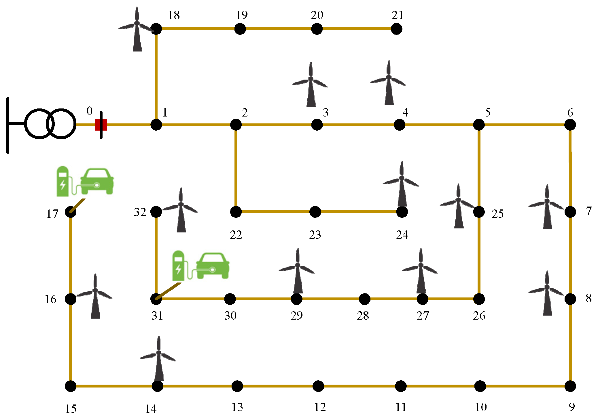
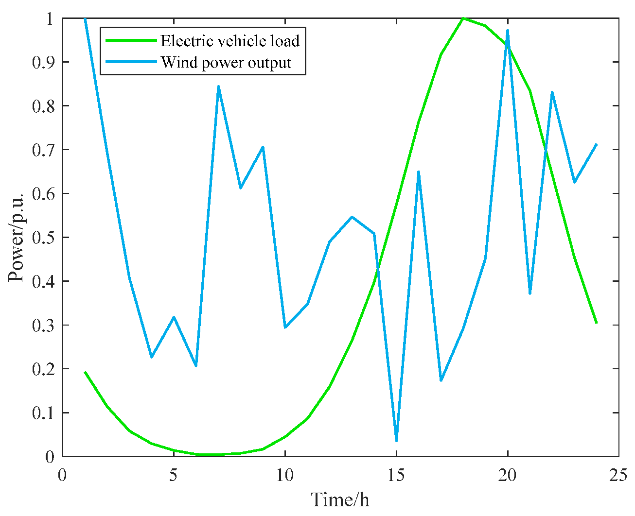
5. Example Analysis

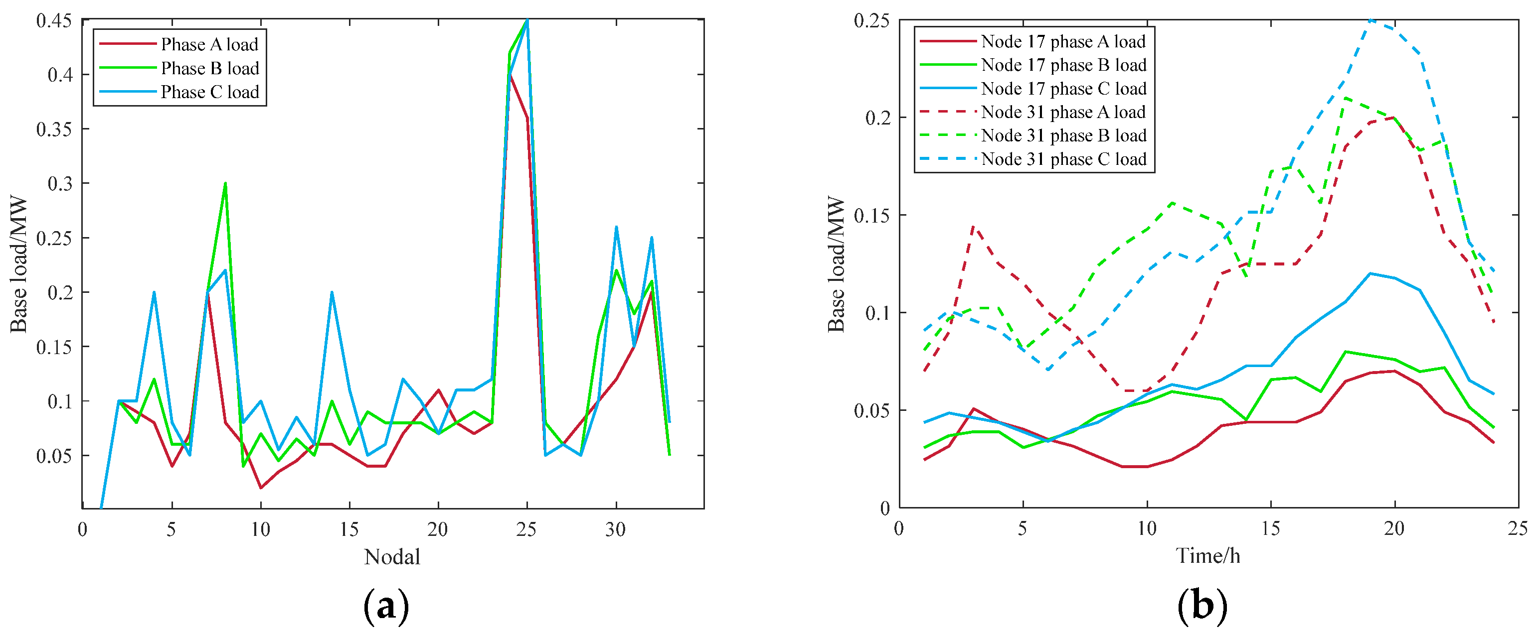
5.1. Basic Load of Power Grid

To confirm the efficacy of the EV charging technique suggested in this research, taking split-phase voltage quality into consideration, a modified IEEE-33 node system is employed. Twelve of the PDN’s nodes have access to a total of 3.36 MW of distributed wind power, while the nodes 17 and 31 have access to 1200 and 800 EVs. The access locations are shown in Figure 4 and have three-phase access and a capacity ratio of 6:4:5. And Figure 5 displays the EV loads and outputs of wind power. The 33 nodes’ base loads and the grid connection sites are displayed in Figure 6, while the overall base active and reactive load of the network are 11.145 MW and 6.9 Mvar, respectively. The PDN’s baseline capacity and voltage are specified as being 100 MVA and 12.66 kV, respectively.

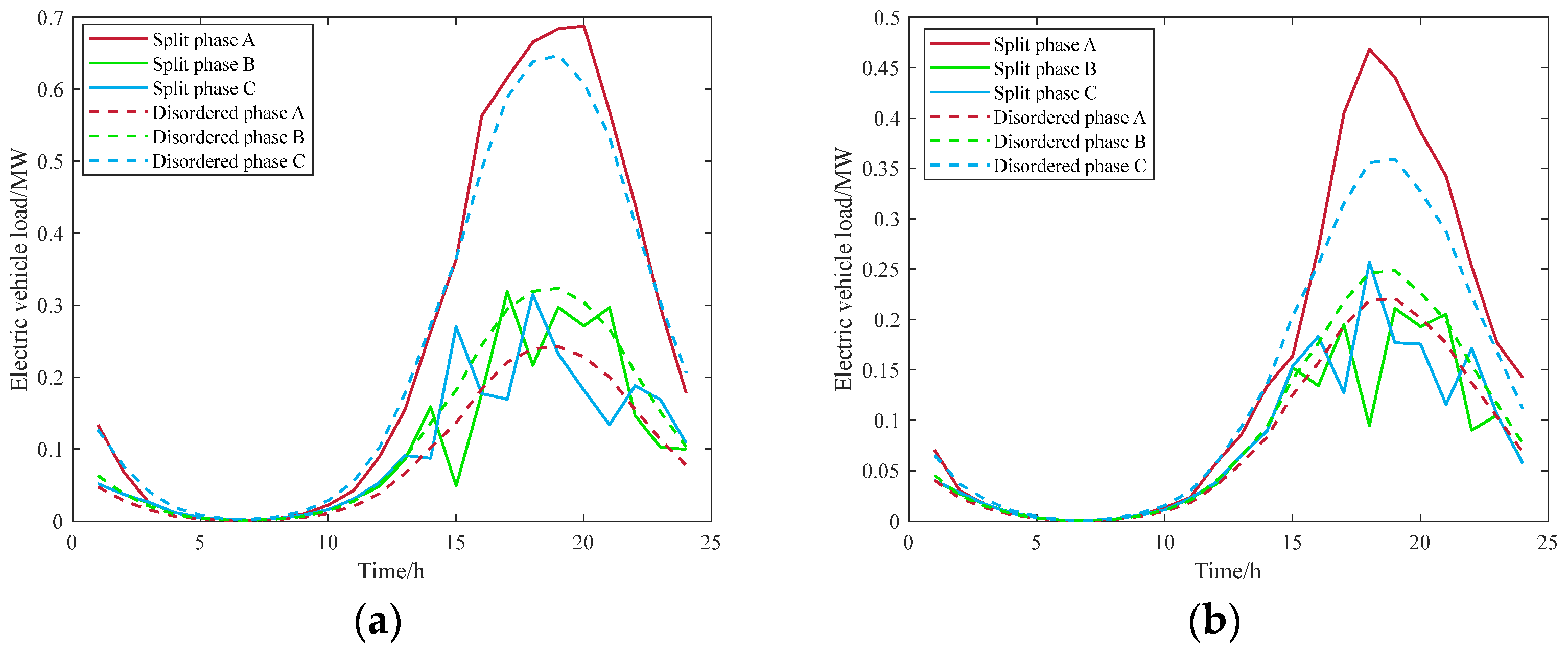
5.2. Results of Phase Selection and Grid Connection of EV

Figure 7a,b show the three-phase load access of EVs at the parallel network point in the case of disordered access and this paper’s charging strategy, respectively. With disordered access, phase C receives the highest EV loads and EV load access is unequal, which exacerbates the unevenness of the system when the base loads are superimposed onto it. In contrast, when it comes to the charging strategy, a larger percentage of EV loads are accessible to phase A to balance the basic three-phase load and reduce voltage quality.
This paper outlines six scenarios that will be compared and analyzed to precisely illustrate the effectiveness of the charging technique in the improvement of voltage quality.
  • Scenario 1: EVs have average access to three-phase charging.
  • Scenario 2: EVs have disorderly access to three-phase charging.
  • Scenario 3: split-phase charging access in accordance with the three voltage quality minimums in this paper as the goal.
  • Scenario 4: only considering the minimum three-phase VU.
  • Scenario 5: only considering the minimum maximum VD of the split-phase.
  • Scenario 6: solely taking into account the lowest VH distortion rate of the parallel network point.
To make the computation results easier to grasp and analyze, the average and maximum values are used to illustrate the improvement in voltage quality. Table 2 exhibits the PDN’s voltage quality under various circumstances.
All of the indicators rise when the EVs are linked with average and disordered access, according to an analysis of Scenarios 1, 2, and 3 in Table 2. This is because, under ordinary and disorderly charging, the increased energy production is not offset, and the three phase load difference is exacerbated by the superposition of the base grid load. The average value of system voltage unbalance is decreased by 24.56% in contrast to the average access case and by 32.81% in contrast to the disordered access scenario, demonstrating the clear improvement in voltage quality level that EV grid charging under the split-phase charging strategy delivers. The average value of the maximum split-phase VD is reduced by 4.90% compared with the average access case, and by 9.11% compared with the disordered access case. The average value of the VH of the grid point is reduced by 6.25% compared with the disordered access case. In terms of the maximum value, the three-phase unbalance and VD under the average and disordered access scenarios are greater than 2% and 7% of the national standard limit, resulting in different degrees of overrun. Additionally, the degree overshoot in the disorderly access scenario exceeds that of the average access scenario. By using the charging approach described in this work, one may guarantee that the voltage quality meets national standards. It is evident that while charging EV in the station, careless charging pile selection will result in significant voltage quality overruns, and a simple average selection of piles cannot meet the voltage quality requirements under new energy access. Split-phase charging of EVs is required to guarantee that the voltage quality satisfies the relevant standards the majority of the time.
From the analysis of scenarios 4, 5, and 6, it is evident that all of them can significantly improve the system’s overall voltage quality when solved with a single voltage quality objective. Specifically, when a single voltage quality objective is used to reach the optimum, the maximum three-phase VU, three-phase VD, and VH distortion rates are 1.78%, 6.53%, and 0.29%, respectively. But accordingly, the other two voltage qualities will be increased to varying degrees, and comparing them with the charging strategy in this paper can allow us to achieve the combined optimum of the three voltage qualities with the minimum comprehensive objective.

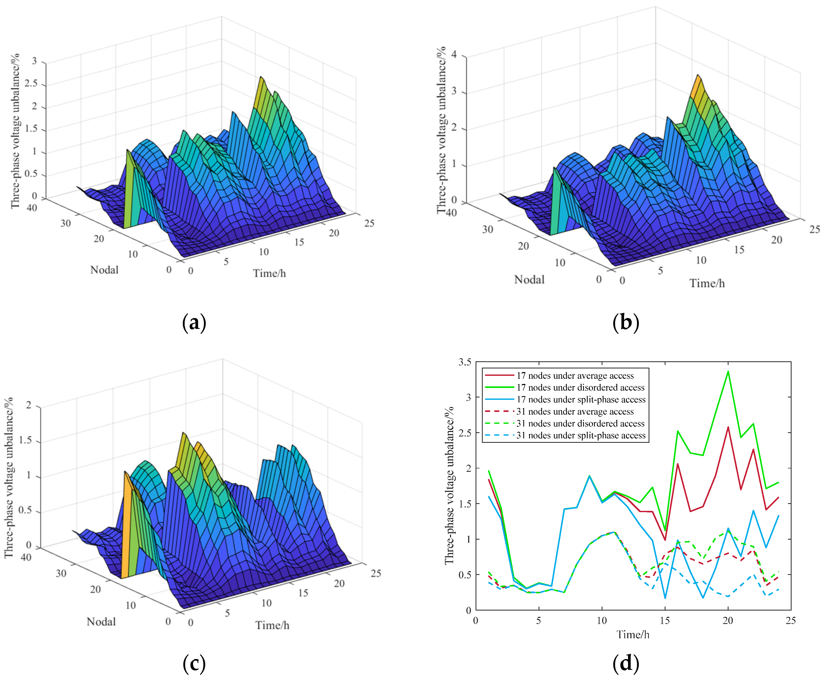
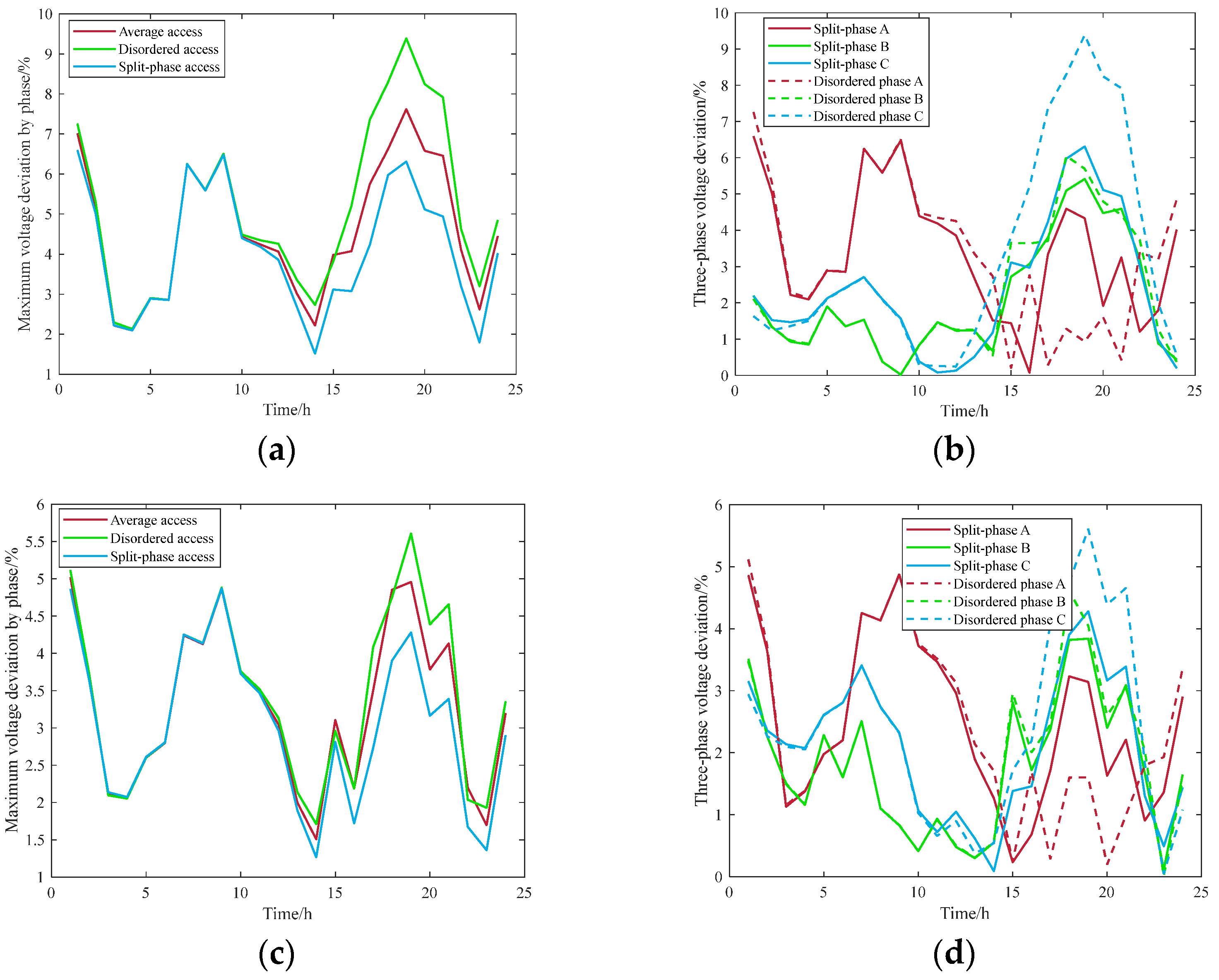
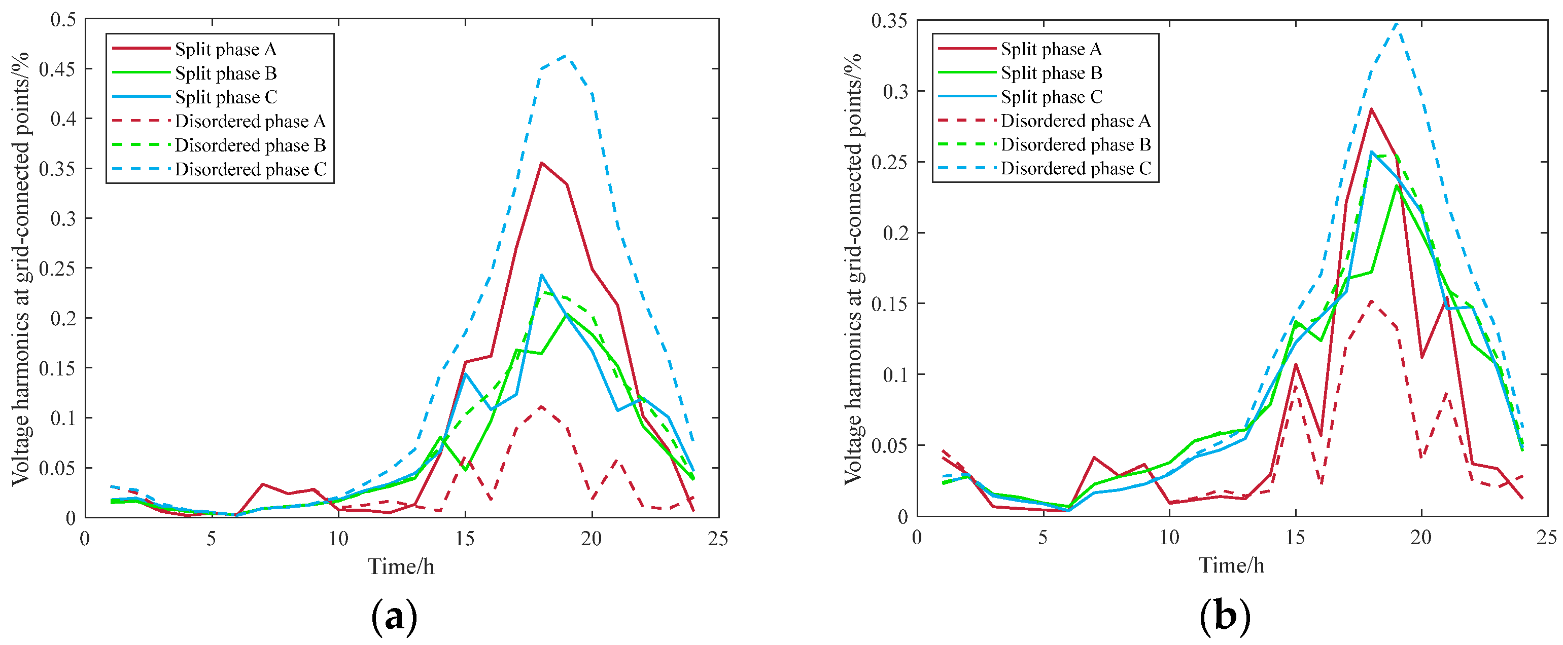
5.3. Improvement of Voltage Quality at Access Points

From the above, it can be seen that the split-phase connection of EVs improves the total voltage quality of the system throughout the day. In this section, the impact of the proposed model on the voltage quality is thoroughly investigated to confirm that the charging strategy described in this paper improves the system’s voltage quality.
Figure 8 shows the three-phase unbalance in the system and the access nodes in three EV access scenarios. From Figure 8a–c, it can be clearly seen that the average and disordered access of EVs lead multiple nodes in multiple moments to produce a three-phase unbalance degree of over-limit. Additionally, the charging approach described in this research significantly lowers the PDN’s degree of three-phase unbalance throughout the day, particularly during the evening’s peak. From Figure 8d, it can be seen that under this paper’s charging strategy, the degree of three-phase unbalance in node 17 and node 31 throughout the day decreases as a whole, where the degree of unbalance in node 17 is 26.20% lower than the average charging and 32.09% lower than the disordered charging, and that of node 31 is 22.07% lower than the average charging and 25.12% lower than the disordered charging. The three-phase VU significantly decreases throughout the day after implementing the charging strategy outlined in this paper, especially at the moment when more EV loads are connected. This is because split-phase charging at the access point selects which EV loads to connect to the phases with lower loads and higher wind power output in order to achieve the three-phase total loads balance, so that overruns will no longer occur.
The VD at the parallel node before and after the split-phase connection of the EV is shown in Figure 9. From Figure 9a,c, it can be seen that the maximum VD of split-phase access at node 17 is reduced to 6.59% from 9.39% and 7.62% on average and out of sequence, while that at node 31 is reduced to 4.28% from 4.96% and 5.61% on average and out of sequence. From Figure 9b,d, it is evident that when split-phase access is used, more EV loads are accessed during the low base load and strong wind output phases; therefore, the three-phase VD is more uniform compared to out of disordered access. After the split-phase connection, more EV loads are connected in the split-phase with a small system load and large wind power output, which makes the three-phase loads relatively close to each other. So that the three-phase VD is more uniform compared to disordered access and is more obvious when there are larger EV loads, and the VDs of each moment in the PDN after the connection are in line with the requirements of the national standard.
The system’s VHs before and after the split-phase and unordered access of EVs are shown in Figure 10a,b. The quantity of load attached to the EV primarily determines the harmonic magnitude. Under the split-phase connection charging strategy, with the EV load suitably dispersed, the harmonic maximum is lowered, and the overall harmonic distortion rate is more uniform in the three phases.

5.4. Effects of Charging Schemes for Varying Numbers of EVs

To confirm that the charging strategy in this paper optimizes the voltage quality for varying numbers of Evs, the voltage quality change for 1000–5000 Evs in 17 nodes with split-phase access and disordered access has been calculated. The of three-phase Evs with disordered access are connected to the grid in accordance with 0.7:0.9:1.4, whereas split-phase access makes use of the charging method outlined in this paper, and the wind power is still accessed using the above access method. The outcome is displayed in Figure 11.
The findings demonstrate that as the number of EVs increases, so do the maximum three-phase VU, the maximum split-phase VD, and the VH distortion rate of the voltage under the scenarios of the average and disordered access of EVs to the network. Meanwhile, a serious overrun situation is created by the disordered access. Despite the fact that average access could possibly lower voltage quality, wind power prevents it from efficiently consuming its output, and still produces a certain degree of over-limit. Split-phase access enhances the voltage quality, and the three-phase VU keeps the level steady without going beyond the limit. This is because the three phase load differential is balanced by the EV loads connected to phase A, which has lower base loads. This proves that EV loads not only do not increase the pressure of three-phase load imbalance when reasonably connected to the grid in split-phase, but also can absorb new energy generation, decrease the VU, and make sure that the VD and VH are also decreased.

6. Conclusions

(1)
In this paper, we propose an electric vehicle charging strategy that takes into account the voltage quality of each phase and design a two-layer algorithm to solve it.
(2)
The inner layer of the algorithm applies the NSGA-II algorithm with an elite strategy to calculate the grid-connected power of each stage of the EV, while the outer layer repeatedly solves the node voltage in each phase using the forward–backward generation method.
(3)
The simulation results indicate that the proposed EV charging technique greatly reduces the split-phase maximum VD, three-phase VU, and VH while making sure the electricity system operates safely and steadily.
The split-phase charging strategy presented in this paper can serve as a theoretical foundation for distribution PDN operators to offer split-phase charging auxiliary services, as well as for policymakers to develop split-phase charging policies, which can encourage EV users to participate in split-phase charging. In the future, further attention can be devoted to the development of split-phase charging prices, with the split-phase charging strategy proposed in this paper serving as a theoretical foundation for such endeavors. In order to balance the grid’s load and achieve lower operating costs, the lower charging price is set in the phase with lower load, guiding the EV load to the phase with lower load. This improves the quality of the voltage in the PDN while providing lower charging costs, and realizing mutual benefits and win-win situations for all parties.

Author Contributions

F.Y.: Conceptualization, Software, Writing—review and editing. M.H.: Visualization, Methodology, Investigation, Supervision, Original draft, Writing—review and editing. F.Z.: Validation– review and editing. X.L.: Post-processing, Supervision—review and editing. All authors have read and agreed to the published version of the manuscript.

Funding

This work was supported by the Science and Technology Project of State Grid Shanxi Electric Power Company (SGSXLF00YCJS2200865).

Data Availability Statement

The original contributions presented in the study are included in the article, further inquiries can be directed to the corresponding author.

Conflicts of Interest

Fulu Yan, Mian Hua, Feng Zhao, and Xuan Liang are employees of Linfen Power Supply Company. This paper is supported by the technology project of State Grid Shanxi Electric Power Company.

References

  1. Huang, L.; Jia, Y.; Han, X.; Wang, P. Tri-level dynamic pricing for charging network operator in coupled power-transportation networks. IEEE Trans. Smart Grid, 2024; early access. [Google Scholar] [CrossRef]
  2. Iqbal, M.N.; Kütt, L.; Daniel, K.; Asad, B.; Shams, G.P. Estimation of Harmonic Emission of Electric Vehicles and Their Impact on Low Voltage Residential Network. Sustainability 2021, 13, 8551. [Google Scholar] [CrossRef]
  3. Kütt, L.; Saarijärvi, E.; Lehtonen, M.; Heigo, M.; Jaan, N. A review of the harmonic and unbalance effects in electrical distribution networks due to EV charging. In Proceedings of the 12th International Conference on Environment and Electrical Engineering, Wroclaw, Poland, 5–8 May 2013. [Google Scholar]
  4. Jorge, N.; Hugo, M.; Rosa, M.D.C.; Jaime, R.A. Strategies Comparison for Voltage Unbalance Mitigation in LV Distribution Networks Using EV Chargers. Electronics 2019, 8, 289. [Google Scholar] [CrossRef]
  5. Wei, H.; Liang, J.; Li, C.; Zhang, Y. Real-time Locally Optimal Schedule for Electric Vehicle Load via Diversity-maximization NSGA-II. J. Mod. Power Syst. Clean Energy 2021, 9, 940–950. [Google Scholar] [CrossRef]
  6. Giuditta, P.; Simona, R.; Gian, G.S.; Davide, F.; Grillo, S.; Francesco, G.; Fabrizio, P. Impact of Electrical Vehicle Private Charging Stations on the Quality of the Low Voltage Network Supply. IEEE Open Access J. Power Energy 2023, 10, 351–362. [Google Scholar]
  7. Liang, H.; Liu, Y.; Li, F.; Shen, Y. Dynamic Economic/Emission Dispatch Including PEVs for Peak Shaving and Valley Filling. IEEE Trans. Ind. Electron. 2019, 66, 2880–2890. [Google Scholar] [CrossRef]
  8. Qu, Z.; Song, J.; Liu, Y.; Lv, H.; Wang, W. Optimization Model of EV Charging and Discharging Price Considering Vehicle Owner Response and Power Grid Cost. J. Electr. Eng. Technol. 2019, 14, 2251–2261. [Google Scholar] [CrossRef]
  9. Gerres, T.; Lukszo, Z. Mitigating production uncertainties of renewables by adjustable load scheduling. In Proceedings of the 2017 IEEE 14th International Conference on Networking, Sensing and Control (ICNSC), Calabria, Italy, 16–18 May 2017. [Google Scholar]
  10. Xu, X.; Li, K.; Wang, F.; Mi, Z.; Jia, Y.; Wei, W.; Jing, Y. Evaluating Multitimescale Response Capability of EV Aggregator Considering Users’ Willingness. IEEE Trans. Ind. Appl. 2021, 57, 3366–3376. [Google Scholar] [CrossRef]
  11. Sergejus, M.; Katarina, K.; Mattia, M. Management of Power Quality Issues in Low Voltage Networks Using Electric Vehicles: Experimental Validation. IEEE Trans. Power Deliv. 2017, 32, 971–979. [Google Scholar]
  12. Lenka, R.; Panda, A.; Patel, R.; Guerrero, J. PV Integrated Multifunctional Off-Board EV Charger With Improved Grid Power Quality. IEEE Trans. Ind. Appl. 2022, 58, 5520–5532. [Google Scholar] [CrossRef]
  13. Shahnia, F.; Wolfs, P.J.; Ghosh, A. Voltage Unbalance Reduction in Low Voltage Feeders by Dynamic Switching of Residential Customers Among Three Phases. IEEE Trans. Smart Grid 2014, 5, 1318–1327. [Google Scholar] [CrossRef]
  14. Nasim, J.; Arindam, G. Online Centralized Coordination of Charging and Phase Switching of PEVs in Unbalanced LV Networks with High PV Penetrations. IEEE Syst. J. 2021, 15, 1015–1025. [Google Scholar]
  15. Zimann, F.J.; Batschauer, A.L.; Mezaroba, M.; Neves, F.A.S. Energy storage system control algorithm for voltage regulation with active and reactive power injection in low-voltage distribution network. Electr. Power Syst. Res. 2019, 174, 105825.1–105825.9. [Google Scholar] [CrossRef]
  16. Ciuceanu, R.M.; Nemoianu, I.V.; Paltanea, V.M.; Paltanea, G. On professor tugulea’s visionary power theory: A review, recent advances and perspectives. Rev. Roum. Des Sci. Tech. 2018, 63, 123–127. [Google Scholar]
  17. Jesus, C.H.; Langella, R.; Cano, A.; Testa, A. Unbalance characteristics of fundamental and harmonic currents of three-phase electric vehicle battery chargers. IET Gener. Transm. Distrib. 2020, 25, 6220–6229. [Google Scholar]
  18. Breda, D.F.J.; Vieira, M.C.J.; Oleskovicz, M. Power Quality Monitor Allocation Based on Singular Value Decomposition and Genetic Algorithm. J. Control Autom. Electr. Syst. 2020, 32, 175–185. [Google Scholar] [CrossRef]
  19. Huang, J.; Wang, X.; Wang, Y.; Shao, C.; Chen, G.; Wang, P. A game-theoretic approach for electric vehicle aggregators participating in phase balancing considering network topology. IEEE Trans. Smart Grid 2024, 15, 743–756. [Google Scholar] [CrossRef]
Figure 1. Electric vehicle phase selection flowchart.
Wevj 15 00315 g001
Figure 2. Schematic diagram of EVs’ access to the grid.
Wevj 15 00315 g002
Figure 3. Bilayer algorithmic flow.
Wevj 15 00315 g003
Figure 4. IEEE-33 node schematic.
Wevj 15 00315 g004
Figure 5. EV load and wind power output.
Wevj 15 00315 g005
Figure 6. Three-phase base load diagrams for PDN nodes and access points. (a) Three-phase base load for IEEE-33 systems; (b) three-phase base load at nodes 17 and 31.
Wevj 15 00315 g006
Figure 7. Load distribution of three-phase EVs at access points before and after split-phase access. (a) Node 17; (b) node 31.
Wevj 15 00315 g007
Figure 8. Overall three-phase unbalance before and after split-phase access for EVs. (a) Average access; (b) Disordered access; (c) Split-phase access; (d) Voltage unbalance at the access point.
Wevj 15 00315 g008
Figure 9. Voltage deviation before and after split-phase access at the access points. (a) Maximum voltage deviation at node 17; (b) three-phase voltage deviation at node 17; (c) maximum voltage deviation at node 31; (d) three-phase voltage deviation at node 31.
Wevj 15 00315 g009
Figure 10. Three-phase voltage harmonics at the access point before and after split-phase access. (a) Node 17; (b) Node 31.
Wevj 15 00315 g010
Figure 11. Voltage quality at node 17 before and after split-phase access with different numbers of EVs. (a) Maximum three-phase voltage unbalance; (b) maximum split-phase voltage deviation; (c) Maximum split-phase voltage harmonics.
Wevj 15 00315 g011
Table 1. Summary of past publications related to the proposed methodology.
LiteratureTarget of ControlOptimization Objective
Peak-to-
Valley
Voltage
Unbalance
Voltage
Deviation
Voltage
Harmonic
[7]Electric Vehicle×××
[8]Electric Vehicle×××
[9]Electric Vehicle×××
[10]Electric Vehicle×××
[11]Control device×××
[12]Control device×××
[13]Control device×××
[14]Control device×××
This articleElectric Vehicle
Note: × means that this factor has not been taken into account, and conversely √ means that this factor is taken into account.
Table 2. Overall voltage quality of PDN under different scenario access.
ScenarioThree-Phase
Voltage Unbalance/%
Maximum Voltage
Deviation by Phase/%
Voltage Harmonics at
Grid-Connected Points/%
Average ValueMaximum ValueAverage ValueMaximum ValueAverage ValueMaximum Value
10.572.543.887.640.150.31
20.643.364.069.390.160.46
30.431.863.696.570.150.36
40.381.783.686.650.150.39
50.421.893.626.530.150.41
60.471.923.766.590.150.29
Disclaimer/Publisher’s Note: The statements, opinions and data contained in all publications are solely those of the individual author(s) and contributor(s) and not of MDPI and/or the editor(s). MDPI and/or the editor(s) disclaim responsibility for any injury to people or property resulting from any ideas, methods, instructions or products referred to in the content.

