Article

A Study on an Energy-Regenerative Braking Model Using Supercapacitors and DC Motors

by
Alistair Teasdale
1,
Lucky Ishaku
1,*,
Chiemela Victor Amaechi
2,3,4,
Ibitoye Adelusi
2 and
Abdelrahman Abdelazim
1
1
Engineering Department, Blackpool & The Fylde College, Bispham, Blackpool FY2 0HB, UK
2
Engineering Department, Lancaster University, Gillow Avenue, Bailrigg, Lancaster LA1 4YW, UK
3
Department of Construction Management, Global Banking School, Devonshire Street North, Manchester M12 6JH, UK
4
Institute of Energy Infrastructure, Universiti Tenaga Nasional, Jalan IKRAM-UNITEN, Kajang 43000, Selangor, Malaysia
*
Author to whom correspondence should be addressed.
World Electr. Veh. J. 2024, 15(7), 326; https://doi.org/10.3390/wevj15070326
Submission received: 20 June 2024 / Revised: 15 July 2024 / Accepted: 16 July 2024 / Published: 22 July 2024
(This article belongs to the Special Issue Power and Energy Systems for E-mobility)

Abstract

:
This study presents an energy regeneration model and some theory required to construct a regeneration braking system. Due to the effects of carbon dioxide (CO2) emissions, there is increasing interest in the use of electric vehicles (EVs), electric bikes, electric bicycles, electric buses and electric aircraft globally. In order to promote the use of electric transportation systems, there is a need to underscore the impact of net zero emissions. The development of EVs requires regenerating braking system. This study presents the advantages of regenerative braking. This system is globally seen in applications such as electric cars, trams, and trains. In this study, the design specification, design methodology, testing configurations, Simulink model, and recommendations will be outlined. A unique element of this work is the practical experiment that was carried out using 1.5 Amps with no load and 2.15 Amps with a load. The discharge voltage was purely from the 22 W bulb load connected to the capacitor bank as we limited this study to the use of 1.5 Amps and it took 15 min for a full discharge cycle, after which no charge was left in the capacitor bank. The results showed that the discharge rate and charging rate for the regenerative braking system were effective but could be improved. The objective of this paper is to investigate how a supercapacitor works alongside a battery in regenerative braking applications. This study demonstrates that the superconductor used can deliver maximum power when required. Also, it can also withstand elevated peaks in charging or discharging current via the supercapacitor. Combining a battery with a supercapacitor reduces the abrupt load on the battery by shifting it to the capacitor. When these two combinations are used in tandem, the battery pack’s endurance and lifespan are both boosted.

1. Introduction

Electric vehicles (EVs) and Battery electric vehicles (BEVs) have seen an increase in market share year by year over the past decade [1]. This is mostly due to the major benefits that EVs and BEVs offer in comparison to conventional vehicles, including the reduction of emissions and the savings on fuel. Additionally, the progress of battery technology and the ongoing reduction in the cost of batteries have contributed to this growth [1,2,3]. Moving a vehicle can use a lot of kinetic energy, due to the number of mechanical parts involved to generate the needed energy. In vehicles that have traditional combustion engines, a massive amount of energy is lost daily as frictional heat while stopping or slowing down. Moreso, when the brake pedals are stepped on while driving, the pads and discs collide during the braking event to slow the vehicle down. The effort made to decelerate or stop the car takes some energy and this form of heat energy cannot be recycled. Conversely, when braking in the electric vehicles (EVs), the kinetic energy is not totally wasted from slowing the vehicle down because the braking effect on the vehicle is created by the motor moving freely without any induced potential energy from the battery. However, the vehicle mass and kinetic energy already created can be used to turn the motor which creates its own excitation voltage. This excitation voltage is used by applying a load to the motor such as a capacitor bank, which will bring in some resistance. The applied resistance will cause the motor to slow down gradually by itself and charging up the capacitor bank to be fed back into the battery pack over time. According to an earlier study submitted at Stanford University [4], regenerative braking extends electric vehicle ranges by as much as 10–25%.
Regenerative braking is very important in different applications such as electric cars because it acts as a braking effect on the motor, which causes the motor to gradually bring the vehicle to a stop. The braking effect is created by applying a load such as a capacitor bank on the motor, which applies resistance, causing the motor to slow down gradually. Sometimes, hydraulic braking is also required for sudden braking conditions; this is mainly required for emergency braking conditions rather than gradual braking, in which case the regenerative braking system will be used. Good braking systems in any vehicle are important because they need to slow down at some point. This also applies to cars, trains, trams, and aircraft. Generally, regenerative braking systems that use the motor to create the braking effect utilize the brakes a lot less as the motor will carry out most of the braking; so, the brake pads and discs do not need as much maintenance compared to the traditional combustion engine vehicle. Thus, brake systems on electric vehicles typically last longer than brake systems on conventional vehicles due to the application of regenerative braking systems [5,6].
However, EVs are challenged with stability, fuel conservation and energy conservation, though recent developments include use of hierarchical controls [7]. In principle, one of the main reasons for the fuel efficiency in EVs is the regenerative braking system used in these vehicles. According to Boretti [8], regenerative braking systems have improved the fuel consumption coverage for the New European Driving Cycle by 25%. This is because the energy is recuperated within the regenerative braking system, thus prolonging the life of the batteries. Therefore, it has a longer range on each charge, and as a result, it reduces the charge cycle time and increases the life of the batteries. Similarly, EVs also have good battery systems as they are known to save energy, thereby having increased fuel economy. Currently, EVs are designed with displays showing simplified mechanisms on the pedal braking, battery savings or/and the energy efficiency indicator. This helps the drivers/users of EVs to know the amount of charge left per trip. Figure 1 illustrates a typical Electric vehicle with regenerative braking system for one-pedal driving.
Studies have shown that regenerative braking applications extend to electric powertrains [9,10,11,12] as the development of electric vehicles involves the use of various component systems. These may include hierarchical control [7], fuzzy logic [13,14] and different forms of DC motors. The form of the DC motors that is used, such as PMDC [15], synchronous motors [16,17,18,19], and BLDC [20,21,22], will be dependent on its design need. Regenerative braking has been carried out on BLDC motors [22,23] and thus also aids the development of batteries and other supercapacitors. Mohammad and Khan [23] presented the operating principles of a controller circuit for the BLDC motor using the Boolean equations for regenerative and motoring modes of operation. For simplification, the behaviors in terms of Boolean equations were used to understand the requirements to construct a controller circuit. In addition, they carried out a cost analysis for the controller design and applied it to an electric rickshaw, which saved some of the energy lost during braking. Another study by Yang et al. [24] carried out a cost analysis on energy-regenerative systems, however, there are other adaptive designs for regenerative braking energy systems. The main purpose of research on energy-regenerative braking applications is energy efficiency [25,26], friction effects [27,28], torque effects [29,30], brake assistant systems [31,32], energy management [33,34], and machine learning [35]. Another method to save energy and improve the handling stability for distributed drive electric vehicles (DDEVs) was proposed by Liang et al. [7,36], however there are several solutions available for EVs’ stability and braking.
In this study, a practical experiment and numerical simulation for regenerative braking systems is presented. In that light, the objective is to obtain generated output gains to charge the capacitor bank, which would indicate the braking effect to charge the capacitors and power the load connected to it. Then, methodology will be presented, followed by the results, along with a Simulink model of regenerative braking system to demonstrate the validation of this model and application of the theory. The findings from this study show that the application of energy-regenerative braking systems is highly beneficial.

2. Literature Review

2.1. Supercapacitors

The role of supercapacitors within an energy braking system is important because it stores the energy that has been created from the braking effect from the motor and transfers the energy back to the batteries over time through a power electronic buck converter. Due to this energy recycling process, EVs have varying battery power per charge. In an earlier review, Leis-Pretto [4] stated that it typically returns 10–25% of power to its supply to gain an extended range.
The reason why supercapacitors are the main desired choice to be used within electric vehicles is that they have excellent power density and cycling characteristics. This is because they have been well explored and tested. For example, the capacitance of a supercapacitor lost 9% of capacitance with a charge and discharge rated when the test was undertaken with 100 Amps charge rate [37]; however, capacitors are not generally charged and discharged with 100 Amps. Electric vehicles contain supercapacitors that are usually housed in a bank formation. This is to allow for a bigger storage density to recuperate as much energy as possible. Supercapacitors generally have a low voltage (2.7 V) and a large charge rating in Farads. So, generally, to gain a higher voltage rating supplied to the capacitors, they are usually connected together in a series transformation rather than in parallel. In addition, electric vehicles have very efficient acceleration and deceleration times compared to traditional vehicles because the capacitors can discharge and charge rapidly to meet the demand for a high amount of power instantaneously, which helps with very fast accelerations and decelerations [38].
Supercapacitors do not hold as much charge capacity as traditional lithium-ion batteries. However, supercapacitors have a very quick power drain depending on the load and can be charged more quickly depending on the input power needed to charge them. Lithium-ion batteries are still the preferred choice for electric vehicles because they can supply the required power needed for a longer duration of time. Supercapacitors can operate with thousands of charge and discharge cycles without deteriorating in performance compared to lithium-ion batteries, which deteriorate and lose their capacity after a thousand cycles [39].
Electric motors can create a lot of stray transients and voltage spikes from the battery and the motor due to unpredictable loads that are needed to power the motor for accelerations and decelerations. This effect can cause stress on the motor and result in heat due to a resistance build-up. To overcome this problem, a smoothing capacitor bank can be placed in parallel to the load across the rectifier output. Figure 2 illustrates the AC/DC waveform showing the rectifier output and the smooth output. Though, as the output voltage increases, the smoothing capacitors will rise and fill up like a reservoir. Thus, when the input voltage decreases, the smoothing capacitors will discharge and flow back to the supply. The main advantage of using smoothing capacitors connected to the load is that it will reduce the ripple effect on the output waveform, and thus, it will not create a noisy DC-varying output [40].
Supercapacitors have a large conductive plate, which is the electrode, and have minimal space between both plates. Traditional capacitors use materials like Teflon and polythene, whereas ultracapacitors use a gel liquid electrolyte and a carbon plate to create a larger charge density at a low voltage with a high farad capacity rating. The construction of supercapacitors includes using a battery system, thus, it can be deem to be similar to that of the electrolytic-type capacitor (see Figure 3). Also, both may be having similar performances but will differ in the output capacity.
The charging time of a supercapacitor is normally in the range of 1 to 10 s and uses a low voltage but high current. The supercapacitor can charge much more quickly if it has a high input current, but it cannot be too high because it will damage the capacitor and the capacitor will lose some of its capacitance rating. For this reason, supercapacitors are the preferred choice when used with regenerative braking systems. The reason is that batteries can only be charged from low current over time whereas supercapacitors charge very quickly. This is due to the high input current and power density, which will discharge over time to re-charge the batteries slowly ([see description in [41]).

2.2. DC Motor Dynamic Braking

Motor dynamic braking uses an electric motor that is converted to a generator by having a moving kinetic force. The motor creates its own electromotive force due to its motion. This enables the motor to produce a potential voltage rating that can be used to power designated loads such as a capacitor bank. As the motor is converted into a generator and a load is applied to the generator, such as a power resistor or a capacitor bank, the generator will create a counter electromotive force on the generator, and it will start to slow down, thus creating a potential difference to charge the capacitors or go through the power resistors to be dissipated as heat [42].
Separate excitation is performed by having the motor field windings connected separately to the supply; this is because the flux in the field windings needs to be kept constant to create a constant electromotive force. As the vehicle moves along freely without any input power, it creates a potential difference, and the motor acts as a generator. Once a load is connected across the generator, it creates a counter electromotive force, causing the motor to slow down very quickly, and the load pulls the energy from the generator to be recycled back into the supply, thus creating the braking effect on the motor and slowing it down [43].
As the motor turns from the kinetic energy without any supply needed to power the motor, it creates its own self-excited electromotive force. Hence, when a load is placed on the motor, it creates a counter electromotive force (emf), pushing against the emf that is already being created by the motor; as this effect will cause the motor to gradually slow down. However, to make the current rating safe, a resistance is connected in series to the field windings, as illustrated in Figure 4 (see [44]. To create a self-excited field within the motor, the field connections must be reversed so that the current flows in the correct direction. This is so that the residual counter electromotive force is created. Subsequently, the motor will operate as a self-excited series generator (see Figure 4).
Frictional braking on a vehicle uses the discs and pads on each wheel to slow it down quickly; however, frictional braking creates a lot of heat. To cool down the discs and pads, they are designed so that cool air blows over them as the car moves along. In addition, frictional brakes still require maintenance, and once the pads and discs are worn out, they will need to be replaced. During maintenance, replacing a full set of discs and brake pads can be very expensive. Also, these parts typically need to be replaced every couple of years depending on the times used, mileage covered and braking conditions.
On the other hand, little or no maintenance is required when using motor dynamic braking because it uses the counter electromotive force to push against the propelled kinetic energy that the motor has already created such that there are no worn-out parts that will need to be replaced. It is like two magnets with both poles facing each other, i.e., they repel each other. Motor dynamic braking uses the same principle but with an electromotive force; though studies are available on similar techniques applied in literature [44,45,46,47,48].

2.3. Power Electronics

Regenerative braking systems require a power converter to safely convert the high amount of power that is stored within the capacitor bank to slowly charge up the batteries. Power electronics in this aspect can be seen to be the transfer of power from the capacitor bank back to the supply. Regenerative braking can be achieved through different methods of operation; for example, a DC-to-DC converter can boost the counter electromotive force to a desired level to charge the batteries back up. The alternative method that could be used is supercapacitors; the charge that has been built up on the capacitors will be sent down to the power electronic converter, which will send a steady charge back to the batteries. Bidirectional DC/DC converters have the task of controlling the flow of the braking energy according to the demands of the vehicle and energy storage. This means that the DC converter performs two roles. The first role is that it transfers the power to the capacitor bank. The second role is that it transfers the power back to the supply once the capacitors are fully charged. However, the DC/DC converter will adjust the voltage level and control the energy flow according to the requirements set by the vehicle.
In order to control the converter in a way that works for the supply and the capacitor bank, it must first charge up the capacitor bank. The DC/DC converter will need to integrate the step-down configuration, which is known as a step-down buck converter. This is because the voltage from the generation will be too high to charge up the capacitors; so, it must be reduced to a safe voltage to charge the capacitors safely, and it must be regulated [49,50]. During the acceleration process, the buck converter will operate within the step-up configuration to discharge the capacitors and boost the power to put it into the motor to be used for the acceleration process [51].

2.4. Application of Regenerative Braking in Cars

There are different applications and developments in regenerative braking systems, including their use in cars, called one-pedal braking. Vasiljević et al. [52] presented a recent review on the applications and working principles of regenerative braking in EVs. On a general note, there are four (4) advantages have been identified as being important for regenerative braking applications by General Motors, as presented by Michaluk [53]. The first is the ease of use, which provides continuous control with fewer pedal transitions, as depicted in Figure 5; the acceleration pedal can dynamically adjust itself to provide responsive propulsion and braking, as depicted in Figure 6; they have good performance with jerk-free stops and less skill required, as depicted in Figure 7; and lastly, they result in energy savings, as seen in the development of electric vehicles (EVs), as shown in Figure 8. The energy savings for one-pedal driving improve the real-world application and development of the electric vehicle (EV) range by increasing regeneration without expensive blended braking systems. This can be seen in the additional energy capture plot for one-pedal driving for the US06 aggressive driving cycle. As the driver continues to propel, energy is captured over time and regenerated in the electric vehicle, thus saving energy.

3. Methodology

3.1. Experimental Model

This section presents the methods that have been implemented to create the circuit design and circuit construction. In addition, the results of the experiment will also be outlined, with details of the practical construction of the regenerative braking system.

3.1.1. Experimental Design Overview

The circuit construction consists of different elements; from the motor drive circuit, which uses four MOSFET power transistors and an Arduino Uno that controls the speed of the DC motor, to the batteries. The first DC motor is connected to the second DC motor to turn it into a generator; as the generator then charges up the supercapacitor bank. Once the capacitor bank is fully charged, it starts to discharge from the load that has been placed across it. All the components were placed on a small piece of plywood; so, it was easy to transport and to outline and present the individual sections within the project (see Figure 9).
Health and safety play a key role in this project because there are harmful hazards that could cause damage and physical harm if they are not outlined and dealt with [54,55,56]. There should also be adequate monitoring of the project to ensure safety. For example, the drive belt connected to the two motors spins at a very fast speed, and if clothing or fingers are caught in the belt, it can cause serious damage. To overcome this hazard, a frame was built around the motor, and a plastic acrylic window was placed on the frame so that it was still possible to see the belt turning. However, this eliminated the risk of having any objects stuck in the belt because it was covered by the acrylic window. The other hazard is that supercapacitors can store a massive amount of charge and can be extremely dangerous if someone accidentally touches the contacts. To control this identified potential electrocution hazard, the frame that was built around the motors was extended to cover the capacitor bank, and an acrylic window was placed over the top of the frame so that it was still possible to see the capacitors, but no one was able to touch them, thus avoiding the risk of electrocution. While our approach in this present study has some novelty in design and findings, there are a range of works on supercapacitors for regenerative braking in EVs that portray different approaches [57,58,59,60,61,62,63,64,65,66,67].

3.1.2. Experimental Circuit Design

Within this study, six supercapacitors were connected in series, with an individual rating of 2.7 V and 500 F. When they were connected in series, they had a rating of 16.2 V and 83.3 F. Figure 10 shows the capacitors charging from a 15 V input DC supply; when using the Multisim software, it provided an unlimited power rating, which means that it is very difficult to compare to when building the project practically. Figure 10 also shows an Amp rating of 276 kA, which is unrealistic and would not happen practically. However, the behavior of the circuit indicates that the capacitors were charging up fully instantly rather than having a steady state current and charging over a period of time. Finally, it was fully charged after some time. Figure 11 shows an Amp rating of 3.2 µA, which indicates that the capacitor is fully charged, and on the oscilloscope, the waveform also shows that it is fully charged.
The circuit design was constructed on Multisim; this was to try and achieve a fully working circuit through a simulation before constructing it practically. This method helped to find errors and design the circuit; so, it was fairly easy to create the circuit practically because there was a circuit diagram to follow. Since Arduino Uno Atmega boards are not available on Multisim’s current version to use within the circuit, there was a triggering signal that could be used instead to turn the MOSFET transistors on via a gate-triggering pulse. Thus, the network in Figure 12 with different charging outputs on the Multimeter. In this design, a 12 V bulb was used instead of using a DC motor for indicating the load, purely for the circuit indication purposes. Contrarily, the actual circuit used a universal series-wound DC motor.

3.1.3. Experimental Circuit Construction

The construction of the regenerative braking system took place on a piece of plywood board. This was because there needed to be enough space on the board to place the relevant components that were needed for the project. On the right side of the setup in Figure 13, the breadboard is located, along with the transistors on it, as well as the Arduino Uno and the 12 V lead acid battery to power the Arduino Uno. On the left side of the motors, the six capacitor banks are located, with two switches above it. The black switch is for applying the capacitive load onto the motor to start the charging process, while the red switch is for discharging the capacitors by applying the 12 V bulb load (see Figure 13).
The 12 V bulb indicates the load that was connected to the capacitor bank. Once the capacitors were fully charged, they needed to be observed then discharged by the bulb. It took approximately 15 min to fully discharge the 22-Watt bulb once the capacitors were charged up to 15 V (see Figure 13).
The supercapacitors were rated individually at 2.7 V 500 farads because the bulb load was rated at 12 V and the capacitors were only rated at 2.7 V; so, they needed to be connected in a series transformation. Once they were connected in series, the new voltage rating was 16.2 V, which was within the threshold of the load rating. The positive and negative tabs on the top of the capacitors were soldered together with a thick cable to make sure they would not be disconnected and that they could support the load current and heat that were being fed to the load from the capacitors; however, in this instance, the load was not too large in capacity as it was only around 22 Watts of power. So, it would not cause any damage, e.g., by heating the capacitors, but if it did cause damage, it would be minimal.
The universal series-wound motor that was used within the braking system consisted of the motor housing frame, brushes, commutator, armature, and field windings. It can run from either a DC or AC power source. When running the motor from an AC power source, the speed is proportional to the frequency that is applied upon it, whereas with DC, a higher torque and higher RPM can be obtained because the motor does not rely on the set frequency; however, one must be careful because if too much DC power is applied, the motor could run above its recommended rating, and that could be very dangerous. To overcome this problem, the motor would need to run from a DC inverter drive where the speed can be varied to the desired setting and also operated. Figure 14 shows the output devices used to obtain the motor’s voltage and current ratings.

3.2. Arduino Programming

The program for the regenerative braking system was created on a compiler and uploaded onto an Arduino processor. The reason that this program had to be made was because the motor that drives the generator needed to be controlled using a speed control circuit. The circuit used four MOSFETS that were connected together, and the gates of the MOSFETS were connected together to pin 9, as shown in Figure 15 on line one: the command is setting pin 9 as the output to the MOSFETS; so, when the pulse-width-modulated signal is set via the potentiometer, the PWM signal will go down pin 9 to trigger the MOSFETS speed setting.

3.3. Numerical Model in Simulink

The numerical model for this study was developed using the MATLAB Simulink package, academic edition, MATLAB version 2020a. The model for the regenerative braking system using DC motors in Simulink was also designed as shown in Figure 16 and the scope readings in Figure 17, Figure 18 and Figure 19. Based on the design, it was simplified to fit a case study for braking using the Simulink package of MATLAB 2020a. This was found to be suitable for the current study. However, it was limited to the demonstration in this study, but leaves room for further works. In these readings, it can be observed that the regenerative braking model was successfully modeled using the DC motor, which can also be carried out using supercapacitors. For the model, two IGBTs, two Diodes, two Pulse generators, two DC voltage sources, one current measurement, one voltage measurement, one Series RLC branch, one scope with two channels, and one Continuous power GUI were utilized in the Simulink model. Different variants of the model were also established based on the individual unit needed. Figure 16 represents a simplified version of the regenerative braking model developed and considered in this study. From the three scope readings in Figure 17, Figure 18 and Figure 19, we can see the amplitude of charge for the current being tested on the circuit.

3.4. Validation Calculations

Some calculations were carried out for the validation of the model using the experiment, as described in this section. This includes the series calculation of the six capacitors used as the energy charge source for the supercapacitor. These are given in Equations (1)–(10), while Equations (11)–(14) are for the peak voltage, average voltage, and root mean square voltage calculations.
S e r i e s   t o t a l   c a p a c i t a n c e = 1 1 500 + 1 500 + 1 500 + 1 500 + 1 500 + 1 500 = 83.33   F
X c = 1 2   π f c = 1 2 π × 50 × 83.3 = 38.2   µ Ω
I d r a i n = 1.3   A     l o a d   P o w e r   d r a i n = 15   V × 1.5   A = 22.5   W
C o n s t a n t   m o t o r   p o w e r   d r a i n = 32   V × 1.55   A = 49.6   W
M o t o r   l o a d   p o w e r   d r a i n = 32   V × 2.15   A = 68.8   W
F i e l d   w i n d i n g   e x c i t a t i o n   p o w e r   r a t i n g = 2.8   V × 1   A = 2.8   W
V 1 = 16.2   V × 500 500 + 500 + 500 + 500 + 500 + 500 = 2.7   V
Q = C × V = 83.3   F × 16.2   V = 1349.46   C
C = Q V = 1349.46 16.2 = 83.3   F
V = Q C = 1349.46 83.3 = 16.2   V
V p e a k = 1.14 × V r m s = 1.14 × 8 = 11.312   V
V r m s = V p e a k × 0.707 = 11.312 × 0.707 = 7.99   V = 8   V
V a v e r a g e = 0.637 × V p e a k = 0.637 × 11.312 = 7.2   V
V a v e r a g e = V r m s 1.11 = 8 1.11 = 7.2   V  

4. Results and Discussion

4.1. Current and Voltage Testing

The main DC drive motor had an input voltage of 32 V and a constant current of 1.55 Amps with no load initiated. The power consumption for the main DC motor was 49.6 Watts. Once the capacitive load was connected from a drive belt to the main DC motor via the generation motor, the revolutions per minute (rpm) slowed down. The reason that it happened was because the load was upon the motor, and there was an increase of 0.6 Amps. As such, the constant current went up to 2.15 Amps and the power rating increased to 68.8 Watts. With the applied load, the power increased by 19.2 Watts.
Since the universal motor was not self-excited, there needed to be a separate excitation voltage and current connected to the field windings to excite them. A voltage of 2.8 Volts and a current of 1 Amp were connected across the field windings to initiate the excitation on the motor to transform it into a generator. As the capacitor bank started to charge up, the load decreased on the drive motor; so, the rpm went up, and the input current started to decrease because the motor had less of a load as the capacitor bank was filling up slowly.
When the capacitors are connected in series, they create a voltage of 16.2 V and a charge rating of 83.3 farads. The input voltage and current from the power supply created enough RPM, which meant the excitation voltage and current from the generator took 15 min to fully charge the capacitor bank to 15 volts. The 12 V bulb load had an average current rating of approximately 1.5 Amps, which created 22 Watts of power. The experimental demonstration presented in Figure 13a,b shows that while testing the circuit, it pulled 1.24 Amps of current, as evident on the Multimeter’s display.

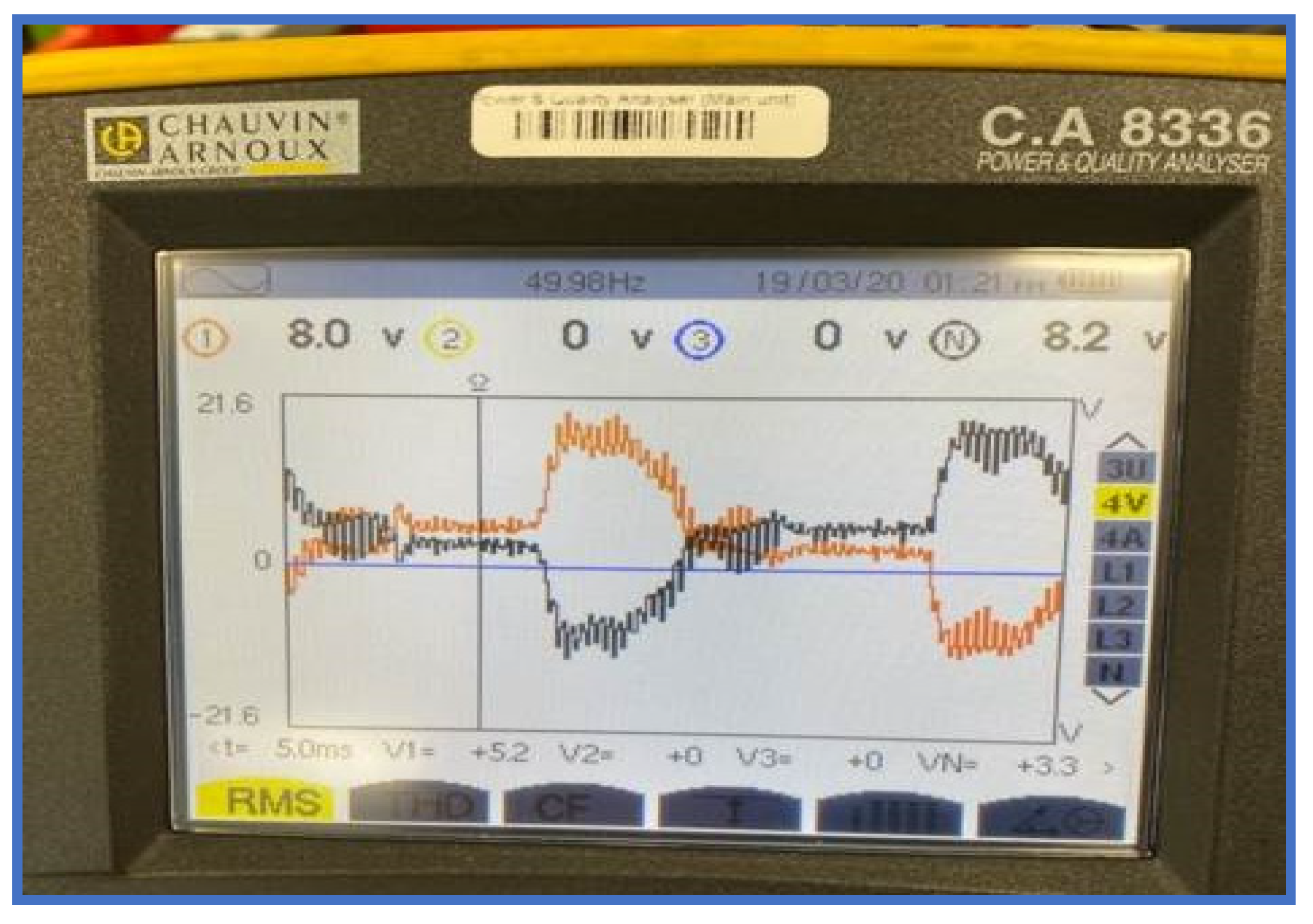
4.2. Waveform Testing

Figure 20 shows two waveforms that indicate the charging process on the capacitor bank. The waveform on Figure 20a shows 833 mV, which indicates that the capacitors are fully discharged and waiting to be charged up again. However, the waveform on Figure 20b shows a rating of 15 V, which indicates that the capacitors are charged up to the desired level.
Conversely, the root mean square (RMS) voltage of the waveform across the charging on the capacitor bank is indicated in Figure 21, which is 8 V. In addition, the peak voltage was also calculated to be 11.312 V, and the average voltage was 7.2 V.

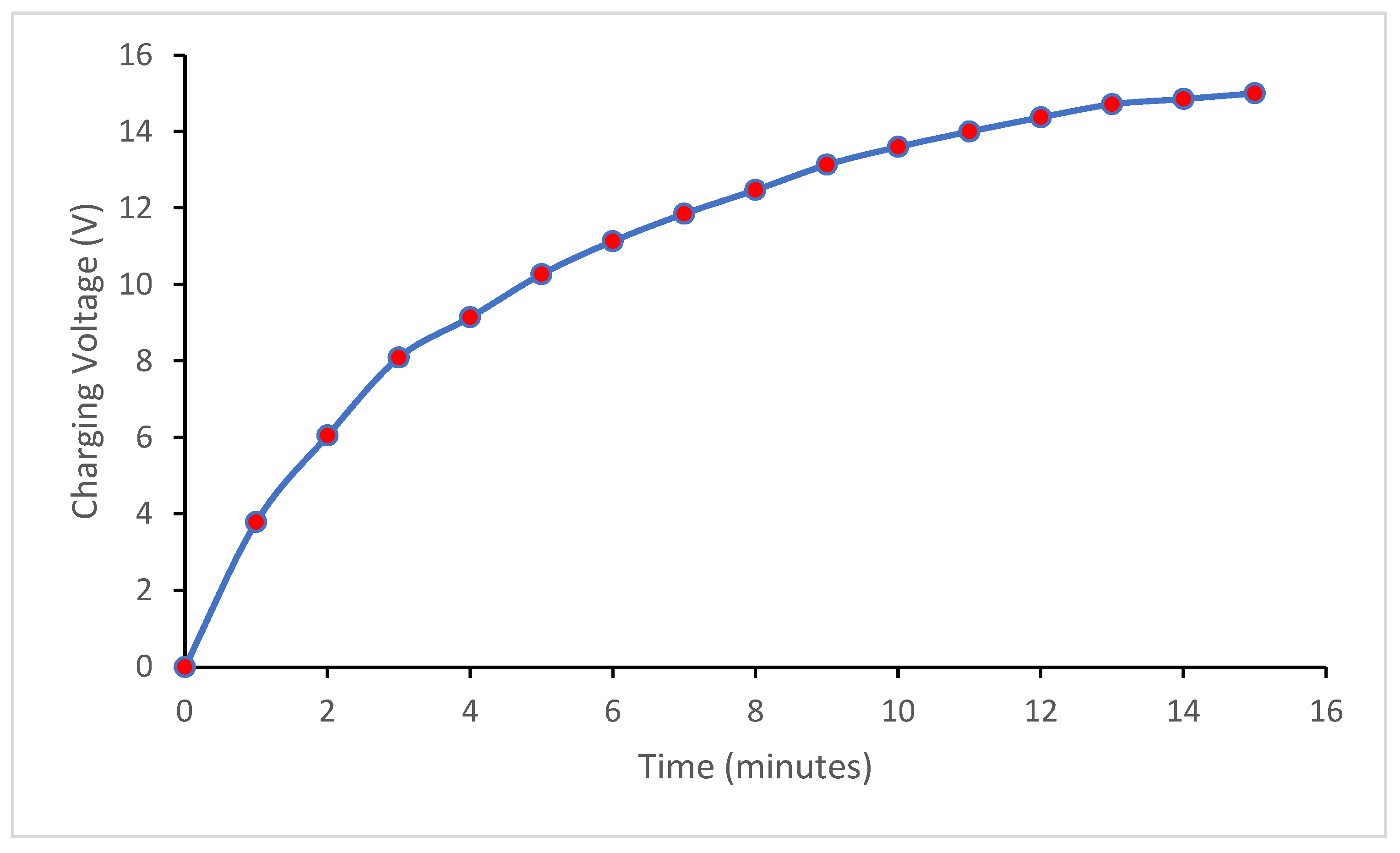
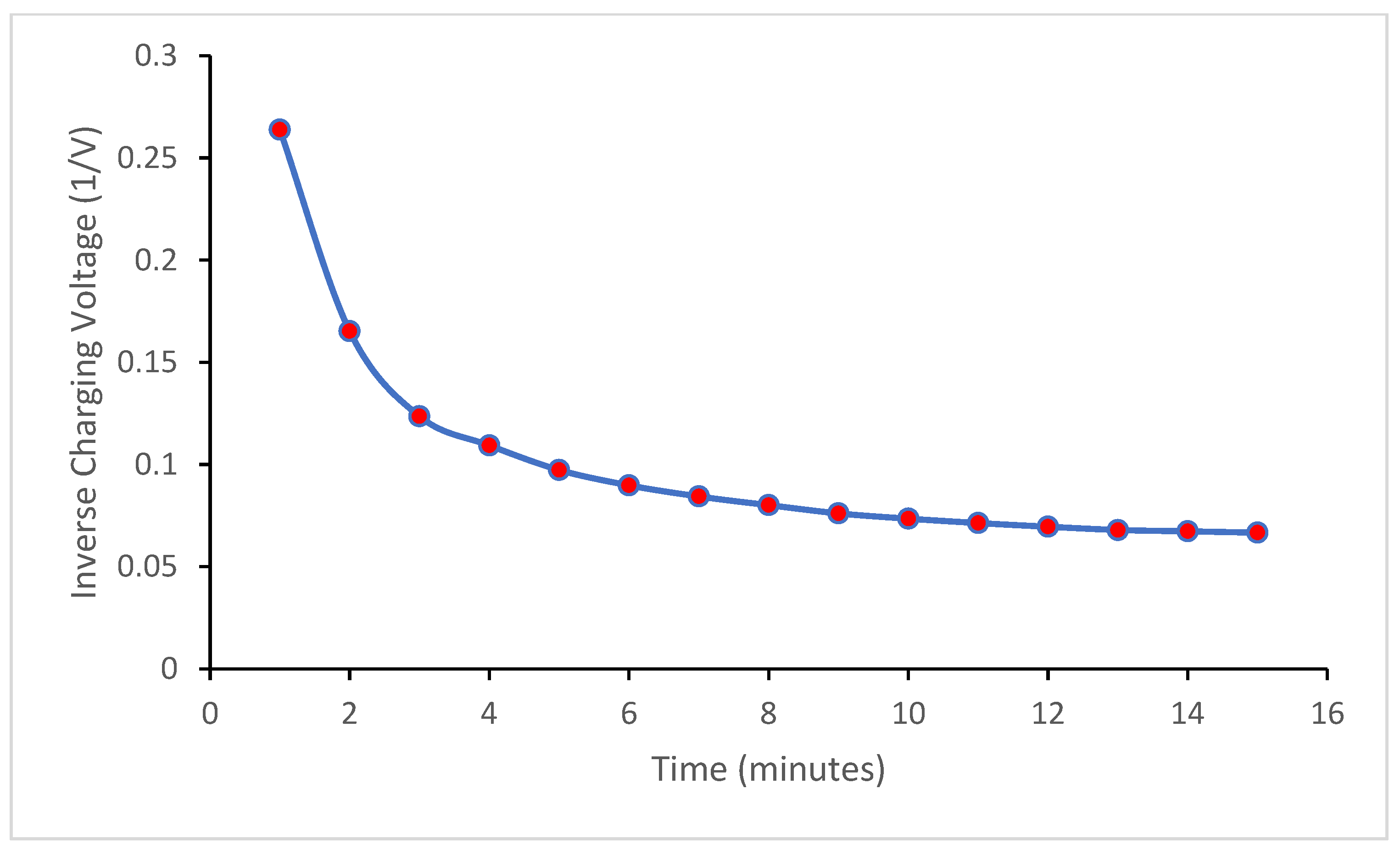
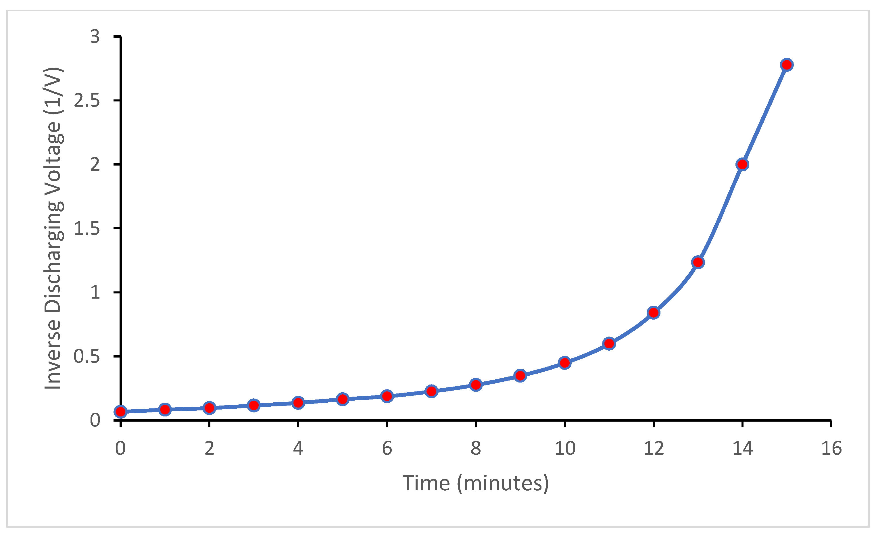
4.3. Charging and Discharge Voltages

The capacitor charging and discharging graphs were created using Excel based on the findings of the experiment. The graphs show the voltage rating against time at a given period. As the capacitor bank started to charge up, the voltage readings were recorded at certain time intervals. During the charging process, there were 15 readings taken at each minute for the total duration of 15 min. The 16th reading taken was the time of origin, at 0 s. Using this method, the data were gathered and used to gain an accurate set of results to create the capacitor charging curve depicted in Figure 22. As shown in Figure 22, the capacitor bank charged up smoothly compared to the time taken.
The capacitor discharging graph was produced using the same tool and was found to be very similar to the charging graph; however, during the discharge, the capacitor bank was discharging rather than charging. The same process of obtaining the voltages per minute for 15 min was also carried out using the same method during the discharge process, as shown in Figure 23. It is evident that the discharge happened a lot faster compared to the charging; however, this depends on the load that was connected and the capacitance rating that was available.
The inverse capacitor charging graph presented in Figure 24 indicates a quick drain upon the capacitor bank. This is shown by the steep curve in Figure 24, and it could indicate a fast acceleration. So, it will need the instant capacitance on the capacitor bank to be drained to go into the motor. For example, it could be a short circuit, which means that the capacitor bank would give the same result as shown in the inverse curve diagram. This is similar to the energy-saving behavior observed by General Motors, as reported by Michaluk [53], shown in Figure 8 as the regenerative braking on the system saves some energy, which can be used for accelerating or devised for another operation in the EV.
However, the inverse capacitor discharge plot shows that during a negative discharge, the system loses some energy, and such a supercapacitor or battery will need to be replaced or switched to another backup supercapacitor, but it regains its charging capacity over time, as shown in Figure 25. With the application of analytical methods for the power law, we obtained Figure 26 and Figure 27 for the regenerative braking capacitive energy system. Figure 26 shows a very good linearity (R2 value of over 97%) between the logarithm of the capacitor charging voltage and the logarithm of the charging time. Linearized capacitor charging and discharging equations were used to produce the graphs, which had R2 values of 94.7 and 96.6, respectively. The gradient of the graphs equated with −1/RC gave capacitors and resistor values very close to the ones used in the implementation, thus validating the results obtained. The graph of the linearized capacitor charging equation is shown in Figure 28, while the graph of the linearized capacitor discharging equation is shown in Figure 29. As seen in Figure 22, Figure 23, Figure 24, Figure 25, Figure 26, Figure 27, Figure 28 and Figure 29, the red dots are the recorded times in minutes obtained during the experiment while charging/discharging, as the case may be. The steps for linearizing both the charging and discharging equations are explained below.
The capacitor charging equation is given as follows:
V c = V s ( 1 e t R C )  
where Vc is the voltage across the capacitor, Vs is the supply voltage, t is the elapsed time since the removal of the supply voltage, and RC is the time constant of the RC discharging circuit.
Conversely, the capacitor discharging equation is,
V c = V s e t R C
Linearizing the capacitor charging equation gives the following:
V c = V s ( 1 e t R C )  
V c = V s V s e t R C
V s V c = V s e t R C
V s V c V s = e t R C
Taking the natural logarithm of both sides gives the following:
ln V s V c V s = t R C
ln V s V c ln V s = t R C
ln V s V c = t R C + ln V s
Compared to the equation of a straight line, y = m x + C , the graph will be a plot of
ln V s V c   against   t
The gradient on the graph is −1/RC, and the intercept is ln Vs.
Linearization of the capacitor discharging equation:
V c = V s e t R C
V c V s = e t R C
Taking the natural logarithm of both sides gives the following:
ln V c V s = t R C
ln V c ln V s = t R C
ln V c = t R C + ln V s
Compared to the straight-line equation, where
y = m x + C
The plot will be in the following form:
ln V c   against   t
On the graph, the gradient is −1/RC, and the intercept is ln Vs.
The analysis of the results shows very good agreement with the literature in terms of an improvement in braking efficiency, recoverability of energy, and system control, as highlighted below:
  • Efficient deceleration is achieved through regenerative braking, but for total stopping force, especially in emergency situations or at low speeds, conventional friction brakes are usually required as well.
  • The seamless transition between regenerative and friction braking is achieved by the application of advanced control algorithms, which further improve driving safety and comfort.
  • Although energy capture efficiency can vary, the result is that EVs will be able to travel farther between charges as a large amount of their kinetic energy can be recovered and used.
  • The battery’s capacity to swiftly and effectively accept and store the regenerated energy has an impact on how successful energy recovery is achieved. The combination of a supercapacitor with a battery makes this even more efficient.
  • Contemporary electric vehicles (EVs) employ advanced electronic control units (ECUs) to regulate the regenerative braking mechanism, maximizing energy recovery while preserving the vehicle’s stability and control [57].
  • Further work could be carried out using neural networks and machine learning methods to optimize the regenerative braking system for EVs (see [35,68]). Also, more work could be done on EV stability and torque control, as different authors consider a range of parameters in their design [69,70,71,72,73,74,75,76,77,78,79]. Lastly, future works could consider the regenerative braking systems for other EVs, plug-in hybrid electric vehicles (PHEVs) and hybrid electric vehicles (HEVs).

5. Conclusions

Currently, there has been an increase in research on electric vehicles, electric trains, electric aircraft, etc. With this increase in renewable energy sources, there is a need for high-performance batteries and energy-regenerative charging systems. This study has successfully presented a design of a regenerative braking system and successfully validated the model. From this study, it can be seen that there are time-dependent gains with regenerative braking systems. In this study, the experiment was carried out using 1.5 Amp with no load and 2.15 Amp with a load. The discharge voltage was purely from the 22 W bulb load connected to the capacitor bank and could only use 1.5 Amps. In addition, it took 15 min for the capacitor bank to be fully discharged. The results showed the discharge rate and the charging rate for the regenerative braking system, as expected, based on the calculations made, and the capacity of the supercapacitors, among other things.
In addition to providing peak power when needed, the supercapacitor can withstand high charging or discharging current peaks. When a battery and supercapacitor are used together, the abrupt load on the battery is shifted to the capacitor, reducing battery heating. The battery pack’s endurance is increased, and its lifespan is prolonged when these two combinations are utilized together. Supercapacitors have the ability to store large amounts of energy in a short amount of time and provide a high amount of power to a load without reducing their lifespan. Supercapacitors also absorb energy during regenerative braking more efficiently than batteries do. This work enhances energy management and the vehicle driving range by utilizing the advantages of batteries and supercapacitors.
Based on the results of this study, it can be concluded that regenerative braking is very important for increasing the range and efficiency of electric vehicles. This has been used in different applications such as electric cars because it acts as a braking effect on the motor, which causes the motor to gradually bring the vehicle to a stop. The braking effect is created by applying a load such as a capacitor bank on the motor, which applies resistance, causing the motor to slow down gradually. Further work could be carried out using neural networks and machine learning methods to optimize the regenerative braking system for EVs. Based on the plots obtained in this study, it can be deduced that despite the time dependence of charging and discharging systems, there is an effect of negative charges or short-circuiting, as seen in the inverse graphs. This is not favorable as they need to discharge slowly to go back into the supply or discharge quickly for acceleration purposes. As shown by the curve, it increases rapidly and then decreases slowly. That implies a fast or sharp drain, followed by a slow drain, which is not good for a regenerative braking system or battery charging system. In this study, the theoretical basis of regenerative braking and supercapacitors for EVs has been presented, although a comprehensive literature review is recommended in future.
Lastly, this study shows the importance of braking in any vehicle because it needs to slow down at some point. Generally, regenerative braking uses the motor to create the braking effect and uses the brakes a lot less. The motor performs most of the braking; so, the brake pads and discs do not need as much maintenance as the traditional combustion engine vehicle. However, there are areas where this study could be improved for future innovations by modifying the simplifications and carrying out larger-scale tests on the supercapacitors. Future works could consider the regenerative braking systems for other EVs, plug-in hybrid electric vehicles (PHEVs) and hybrid electric vehicles (HEVs).

Author Contributions

Conceptualization, A.T., L.I., C.V.A. and A.A.; methodology, A.T., L.I., C.V.A. and A.A.; software, A.T., L.I., C.V.A. and A.A.; validation, A.T., L.I., C.V.A., I.A. and A.A.; formal analysis, A.T. and L.I.; investigation, A.T., L.I., C.V.A., I.A. and A.A.; resources, A.T., L.I., C.V.A. and A.A.; data curation, A.T., L.I. and C.V.A.; writing—original draft preparation, A.T., L.I. and C.V.A.; writing—review and editing, A.T., L.I., C.V.A., I.A. and A.A.; visualization, A.T., L.I., C.V.A., I.A. and A.A.; supervision, A.T., L.I., C.V.A., I.A. and A.A.; project administration, A.T., L.I., C.V.A., I.A. and A.A.; funding acquisition, A.T., L.I., C.V.A., I.A. and A.A. All authors have read and agreed to the published version of the manuscript.

Funding

This research was funded by B&FC 2024 research funding.

Data Availability Statement

The original contributions presented in the study are included in the article, further inquiries can be directed to the corresponding author.

Acknowledgments

The authors appreciate the support of both Lancaster University School of Engineering and Blackpool and The Fylde College (B&FC) for the support in carrying out this research work. The research was also part of work conducted for a degree award in B&FC. The authors also acknowledges the support of UNITEN’s BOLD25 Initiative.

Conflicts of Interest

The authors declare no conflicts of interest.

References

  1. Schafer, D.; Lamantia, M.; Chen, P. Modeling and Spacing Control for an Electric Vehicle with One-Pedal-Driving Feature. In Proceedings of the 2021 American Control Conference (ACC), New Orleans, LA, USA, 25–28 May 2021; pp. 166–171. [Google Scholar] [CrossRef]
  2. Adelusi, I.; Amaechi, C.V.; Andrieux, F.; Dawson, R. Multiphysics simulation of added carbon particles within fluidized bed anode zinc-electrode. Eng. Res. Express J. ERX 2020, 2, 025014. [Google Scholar] [CrossRef]
  3. Adelusi, I.; Amaechi, C.V.; Andrieux, F.; Dawson, R. Practical Development of a ZnBr2 Flow Battery with a Fluidized Bed Anode Zinc-Electrode. J. Electrochem. Soc. 2020, 167, 050504. [Google Scholar] [CrossRef]
  4. Leis-Pretto, J. Regenerative Braking. 2017. Submitted on November 8, 2017 as PH240 coursework, Stanford University, Fall 2017. Available online: http://large.stanford.edu/courses/2017/ph240/leis-pretto1/ (accessed on 15 July 2024).
  5. EERE. Electric Car Safety, Maintenance, and Battery Life. 2020. Energy Efficiency & Renewable Energy (EERE), U.S. Department of Energy. Available online: https://www.energy.gov/eere/electricvehicles/electric-car-safety-maintenance-and-battery-life (accessed on 20 March 2020).
  6. AFDC. Maintenance and Safety of Electric Vehicles. 2024. Alternative Fuel Data Center (AFDC), U.S. Department of Energy. Available online: https://afdc.energy.gov/vehicles/electric-maintenance (accessed on 15 July 2024).
  7. Liang, J.; Wang, F.; Feng, J.; Zhao, M.; Fang, R.; Pi, D.; Yin, G. A hierarchical control of independently driven electric vehicles considering handling stability and energy conservation. IEEE Trans. Intell. Veh. 2023, 9, 738–751. [Google Scholar] [CrossRef]
  8. Boretti, A.A. Improvements of vehicle fuel economy using mechanical regenerative braking. Int. J. Veh. Des. 2011, 55, 35–48. [Google Scholar] [CrossRef]
  9. Jo, J.; Ko, J.; Yeo, H.; Yeo, T.; Hwang, S.; Kim, H. Cooperative regenerative braking control algorithm for an automatic transmission-based hybrid electric vehicle during a downshift. Proc. Inst. Mech. Eng. Part D J. Automob. Eng. 2012, 226, 457–467. [Google Scholar] [CrossRef]
  10. Bai, Z.-F.; Cao, B.-G.; Li, S.-X.; Kang, L.-Y. Simulation on H robust control for regenerative braking of electric vehicle. J. Syst. Simul. 2005, 17, 2975–2978. [Google Scholar]
  11. Ye, M.; Jiao, S.; Cao, B. Energy recovery for the main and auxiliary sources of electric vehicles. Energies 2010, 3, 1673–1690. [Google Scholar] [CrossRef]
  12. Yin, G.; Jin, X. Cooperative control of regenerative braking and antilock braking for a hybrid electric vehicle. Math. Probl. Eng. 2013, 2013, 9. [Google Scholar] [CrossRef]
  13. Zhou, M.; Bi, S.; Dong, C.; He, C. Regenerative braking system for electric vehicles based on genetic algorithm fuzzy logic control. ICIC Express Lett. Part B Appl. 2014, 5, 689–695. [Google Scholar]
  14. Jansen, S.; Alirezaei, M.; Kanarachos, S. Adaptive regenerative braking for electric vehicles with an electric motor at the front axle using the state dependent riccati equation control technique. WSEAS Trans. Syst. Control 2014, 9, 424–437. [Google Scholar]
  15. Chuang, H.-S.; Chuang, Y.-C.; Chen, C.-Y. Development of two-quadrant PMDC motor drives with regenerative braking on electric vehicles. ICIC Express Lett. 2011, 5, 3321–3328. [Google Scholar] [CrossRef]
  16. Su, Y.X.; Zheng, C.H.; Duan, B.Y. Automatic disturbances rejection controller for precise motion control of permanent magnet synchronous motors. IEEE Trans. Ind. Electron. 2005, 52, 814–823. [Google Scholar] [CrossRef]
  17. Yu, T.; Tong, J.P. Auto disturbance rejection control of microturbine system. In Proceedings of the 2008 IEEE Power and Energy Society General Meeting—Conversion and Delivery of Electrical Energy in the 21st Century, Pittsburgh, PA, USA, 20–24 July 2008; pp. 1–6. [Google Scholar] [CrossRef]
  18. Han, J. From PID to active disturbance rejection control. IEEE Trans. Ind. Electron. 2009, 56, 900–906. [Google Scholar] [CrossRef]
  19. Han, J.Q. Auto disturbances rejection control technique. Front. Sci. 2007, 1, 24–31. (In Chinese) [Google Scholar]
  20. Abdi, H.; Bahrami, H.; Mirtalaei, S.M.M. Simplified design and optimization of slotless brushless DC machine for micro-satellites electro-mechanical batteries. J. Electr. Eng. Technol. 2013, 8, 124–129. [Google Scholar] [CrossRef]
  21. Wu, H.-X.; Cheng, S.-K.; Cui, S.-M. A controller of brushless DC motor for electric vehicle. IEEE Trans. Magn. 2005, 41, 509–513. [Google Scholar] [CrossRef]
  22. Wen, J.P.; Zhang, C.W. Research on modeling and control of regenerative braking for brushless DC machines driven electric vehicles. Math. Probl. Eng. 2015, 2015, 1–6. [Google Scholar] [CrossRef]
  23. Mohammad, A.; Khan, M.Z.R. BLDC motor controller for Regenerative Braking. In Proceedings of the 2015 International Conference on Electrical Engineering and Information Communication Technology (ICEEICT), Dhaka, Bangladesh, 21–23 May 2015; pp. 1–6. [Google Scholar] [CrossRef]
  24. Yang, M.; Jhou, H.; Ma, B.; Shyu, K. A Cost-Effective Method of Electric Brake with Energy Regeneration for Electric Vehicles. IEEE Trans. Ind. Electron. 2009, 56, 2203–2212. [Google Scholar] [CrossRef]
  25. Du, J.; Chen, J.; Gao, M.; Wang, J. Energy efficiency-oriented design method of power management strategy for range-extended electric vehicles. Math. Probl. Eng. 2016, 2016, 1–9. [Google Scholar] [CrossRef]
  26. Qiu, C.; Wang, G. New evaluation methodology of regenerative braking contribution to energy efficiency improvement of electric vehicles. Energy Convers. Manag. 2016, 119, 389–398. [Google Scholar] [CrossRef]
  27. Kumar, C.N.; Subramanian, S.C. Cooperative control of regenerative braking and friction braking for a hybrid electric vehicle. Proc. Inst. Mech. Eng. Part D J. Automob. Eng. 2016, 230, 103–116. [Google Scholar] [CrossRef]
  28. Kwon, H.; Park, J.H.; Gwak, G.S.; Huh, J.W.; Choi, H.K.; Hwang, S.H. Cooperative control for friction and regenerative braking systems considering dynamic characteristic and temperature condition. Int. J. Automot. Technol. 2016, 17, 437–446. [Google Scholar] [CrossRef]
  29. Li, W.; Du, H.; Li, W. A new torque distribution strategy for blended anti-lock braking systems of electric vehicles based on road conditions and driver’s intentions. SAE Int. J. Passeng. Cars—Mech. Syst. 2016, 9, 107–115. [Google Scholar] [CrossRef]
  30. Zhao, X.; Xu, S.; Ye, Y.; Yu, M.; Wang, G. Composite braking AMT shift strategy for extended-range heavy commercial electric vehicle based on LHMM/ANFIS braking intention identification. Clust. Comput. 2018, 22, 8513–8528. [Google Scholar] [CrossRef]
  31. Li, W.; Du, H.; Li, W. Driver intention based coordinate control of regenerative and plugging braking for electric vehicles with in-wheel PMSMs. IET Intell. Transp. Syst. 2018, 12, 1300–1311. [Google Scholar] [CrossRef]
  32. Hirose, T.; Taniguchi, T.; Hatano, T.; Takahashi, K.; Tanaka, N. A study on the effect of brake assist systems (BAS). SAE Int. J. Passeng. Cars—Mech. Syst. 2009, 1, 729–735. [Google Scholar] [CrossRef]
  33. Chen, Z.; Liu, W.; Yang, Y.; Chen, W. Online energy management of plug-in hybrid electric vehicles for prolongation of all electric range based on dynamic programming. Math. Probl. Eng. 2015, 2015, 1–11. [Google Scholar] [CrossRef]
  34. Xi, L.; Zhang, X.; Sun, C.; Wang, Z.; Hou, X.; Zhang, J. Intelligent energy management control for extended range electric vehicles based on dynamic programming and neural network. Energies 2017, 10, 1871. [Google Scholar] [CrossRef]
  35. Xing, Y.; Lv, C.; Huaji, W.; Wang, H.; Cao, D. Recognizing Driver Braking Intention with Vehicle Data Using Unsupervised Learning Methods; SAE Technical Papers 2017-01-0433; SAE: Warrendale, PA, USA, 2017. [Google Scholar] [CrossRef]
  36. Liang, J.; Feng, J.; Fang, Z.; Lu, Y.; Yin, G.; Mao, X.; Wu, J.; Wang, F. An Energy-Oriented Torque-Vector Control Framework for Distributed Drive Electric Vehicles. IEEE Trans. Transp. Electrif. 2023, 9, 4014–4031. [Google Scholar] [CrossRef]
  37. Partridge, J.; Abouelamaimen, D.I. The Role of Supercapacitors in Regenerative Braking Systems. Energies 2019, 12, 2683. [Google Scholar] [CrossRef]
  38. Andrew Burke, H.Z. Applications of Supercapacitors in Electric and Hybrid Vehicles. 2015. Available online: https://steps.ucdavis.edu/wp-content/uploads/2017/05/2015-UCD-ITS-RR-15-09-1.pdf (accessed on 11 April 2020).
  39. Dixon, J.W. Regenerative Braking for an Electric Vehicle Using Ultracapacitors and a Buck-Boost Converter. 2019. Available online: https://pdfs.semanticscholar.org/c8dc/f4d7c83f099d9e563c8c37596e06b181d264.pdf (accessed on 2 March 2020).
  40. Mao, S. Looking Closer at Smoothing Capacitors in Electric Vehicles. 2019. Available online: https://blog.knowlescapacitors.com/blog/looking-closer-at-smoothing-capacitors-in-electric-vehicles (accessed on 4 March 2020).
  41. Electronics Tutorials. Ultracapacitors. 2020. Available online: https://www.electronics-tutorials.ws/wp-content/uploads/2018/05/capacitor-cap50.gif (accessed on 4 March 2020).
  42. Csanyi, E. Two Basic Methods for Braking a Motor (DC Injection and Dynamic Braking). Published on 18th April, 2016. Electrical Engineering Portal (EEP). 2016. Available online: https://electrical-engineering-portal.com/methods-braking-motor (accessed on 11 April 2020).
  43. Olabi, A.G.; Abdelkareem, M.A.; Wilberforce, T.; Alkhalidi, A.; Salameh, T.; Abo-Khalil, A.G.; Hassan, M.M.; Sayed, E.T. Battery electric vehicles: Progress, power electronic converters, strength (S), weakness (W), opportunity (O), and threats (T). Int. J. Thermofluids 2022, 16, 100212. [Google Scholar] [CrossRef]
  44. Karthik, S.R. How Regenerative Braking Works in Electric Vehicles. Published on 25 July 2019. Circuitdigest. 2019. Available online: https://circuitdigest.com/article/how-regenerative-braking-works-in-electric-vehicles (accessed on 24 March 2020).
  45. Circuitglobe. Dynamic Braking or Rheostatic Braking of DC Motor. CircuitGlobe. 2020. Available online: https://circuitglobe.com/dynamic-braking-or-rheostatic-braking-of-dc-motor.html (accessed on 13 March 2020).
  46. ConnectUSFund. 6 Advantages and Disadvantages of Regenerative Braking System. ConnectUSFund. 2018. Available online: https://connectusfund.org/6-advantages-and-disadvantages-of-regenerative-braking-system (accessed on 27 February 2020).
  47. Woodford, C. How Regenerative Brakes Work. Published on 6th September, 2022. Explain That Stuff. 2022. Available online: https://www.explainthatstuff.com/how-regenerative-brakes-work.html (accessed on 4 April 2020).
  48. Buchmann, I. How Does a Supercapacitor Work? Battery University, Cadex Electronics Inc. 2019. Available online: https://batteryuniversity.com/learn/article/whats_the_role_of_the_supercapacitor (accessed on 7 March 2020).
  49. Hernandez-Ochoa, J.C.; Alejo-Reyes, A.; Rosas-Caro, J.C.; Valdez-Resendiz, J.E. Improved Operation of the Step-Up Converter with Large Voltage Gain and Low Voltage on Capacitors. Appl. Sci. 2023, 13, 2854. [Google Scholar] [CrossRef]
  50. Kapat, S.; Krein, P.T. Improved time optimal control of a buck converter based on capacitor current. IEEE Trans. Power Electron. 2011, 27, 1444–1454. [Google Scholar] [CrossRef]
  51. Zupan, T.; Stih, Z.; Trkulja, B. Fast and precise method for inductance calculation of coaxial circular coils with rectangular cross section using the one-dimensional integration of elementary functions applicable to superconducting magnets. IEEE Trans. Appl. Supercond. 2014, 24, 81–89. [Google Scholar] [CrossRef]
  52. Vasiljević, S.; Aleksandrović, B.; Glišović, J.; Maslać, M. Regenerative braking on electric vehicles: Working principles and benefits of application. In IOP Conference Series: Materials Science and Engineering; IOP Publishing: Bristol, UK, 2022; Volume 1271, p. 012025. [Google Scholar] [CrossRef]
  53. Michaluk, N. One-Pedal Driving Rapid Feature Development with Simulink. In Proceedings of Mathworks’ 2017 Automotive Conference. 2017. Available online: https://www.mathworks.com/content/dam/mathworks/mathworks-dot-com/solutions/automotive/files/mac2017/one-pedal-driving-rapid-feature-development-with-simulink.pdf (accessed on 15 July 2024).
  54. Amaechi, C.V.; Reda, A.; Kgosiemang, I.M.; Ja’e, I.A.; Oyetunji, A.K.; Olukolajo, M.A.; Igwe, I.B. Guidelines on Asset Management of Offshore Facilities for Monitoring, Sustainable Maintenance, and Safety Practices. Sensors 2022, 22, 7270. [Google Scholar] [CrossRef]
  55. Amaechi, C.V.; Reda, A.; Ja’e, I.A.; Wang, C.; An, C. Guidelines on Composite Flexible Risers: Monitoring Techniques and Design Approaches. Energies 2022, 15, 4982. [Google Scholar] [CrossRef]
  56. Amaechi, C.V.; Hosie, G.; Reda, A. Review on Subsea Pipeline Integrity Management: An Operator’s Perspective. Energies 2023, 16, 98. [Google Scholar] [CrossRef]
  57. Jamadar, N.M.; Jadhav, H.T. Effectiveness of supercapacitor during braking operation of electric vehicle. Mater. Today Proc. 2022, 56, 314–319. [Google Scholar] [CrossRef]
  58. Kabasawa, K.; Kimura, K.; Taguchi, T.; Anekawa, A. Development of a New Powertrain for Subcompact Electric Vehicles; SAE Technical Paper 2013-01-1478; SAE: Warrendale, PA, USA, 2013. [Google Scholar] [CrossRef]
  59. Eichhorn, B.; König, S.; Ullrich, T. Electronic brake control for greater active safety. ATZ Worldw. 2014, 116, 50–53. [Google Scholar] [CrossRef]
  60. Schick, B.; Büttner, R.; Baltruschat, K.; Meier, G.; Jakob, H. Evaluation methods for the function and quality of driver assistance systems with active brake control. ATZ Worldw. 2007, 109, 14–18. [Google Scholar] [CrossRef]
  61. Xiao, B.; Lu, H.; Wang, H.; Ruan, J.; Zhang, N. Enhanced regenerative braking strategies for electric vehicles: Dynamic performance and potential analysis. Energies 2017, 10, 1875. [Google Scholar] [CrossRef]
  62. Tran, D.; Sheng, W.; Liu, L.; Liu, M. A Hidden Markov Model based driver intention prediction system. In Proceedings of the 5th Annual IEEE International Conference on Cyber Technology in Automation, Control and Intelligent Systems, IEEE-CYBER, Shenyang, China, 8–12 June 2015; pp. 115–120. [Google Scholar] [CrossRef]
  63. Zhang, D.; Zong, C.; Wan, Y.; Zheng, H.; Zhao, W.-Q. Development and Research on Control Strategy of Advanced Electronic Braking Systems for Commercial Vehicle; SAE Technical Paper 2014-01-2285; SAE: Warrendale, PA, USA, 2014. [Google Scholar] [CrossRef]
  64. Pan, H.; Guo, X.; Pei, X.; Pan, J.; Zhang, J. Research on Regenerative Braking Control Strategy of Distributed EV Based on Braking Intention; SAE Technical Paper 2018-01-1342; SAE: Warrendale, PA, USA, 2018. [Google Scholar] [CrossRef]
  65. Choi, J.; Jeong, J.; Park, Y.-I.; Cha, S.W. Evaluation of regenerative braking effect for E-REV bus according to characteristic of driving cycle. Int. J. Precis. Eng. Manuf.—Green Technol. 2015, 2, 149–155. [Google Scholar] [CrossRef]
  66. Heine, J.; Sylla, M.; Langer, I.; Schramm, T.; Abendroth, B.; Bruder, R. Algorithm for driver intention detection with fuzzy logic and edit distance. In Proceedings of the 18th IEEE International Conference on Intelligent Transportation Systems, ITSC 2015, Las Palmas de Gran Canaria, Spain, 15–18 September 2015; pp. 1022–1027. [Google Scholar] [CrossRef]
  67. Geraee, S.; Mohammadbagherpoor, H.; Shafiei, M.; Valizadeh, M.; Montazeri, F.; Feyzi, M.R. Regenerative braking of electric vehicle using a modified direct torque control and adaptive control theory. Comput. Electr. Eng. 2018, 69, 85–97. [Google Scholar] [CrossRef]
  68. Cao, J.-B.; Cao, B.-G. Neural network sliding mode control based on on-line identification for electric vehicle with ultracapacitor-battery hybrid power. Int. J. Control. Autom. Syst. 2009, 7, 409–418. [Google Scholar] [CrossRef]
  69. Zhou, K.; Chen, L.; Pan, C.; Chen, L.; Wang, X. Electric vehicle regenerative braking system based on constant current control of composite power sources. J. Mech. Eng. 2013, 49, 78–83. [Google Scholar] [CrossRef]
  70. Miller, M.; Holmes, A.; Conlon, B.; Savagian, P. The GM ‘Voltec’ 4ET50 multi-mode electric transaxle. SAE Int. J. Engines 2011, 4, 1102–1114. [Google Scholar] [CrossRef]
  71. Peng, B.; Zhang, H.; Xuan, G.; Xiao, W. Torque distribution strategy of electric vehicle with in-wheel motors based on the identification of driving intention. Automot. Innov. 2018, 1, 140–146. [Google Scholar] [CrossRef]
  72. Fang, S.; Song, J.; Song, H.; Tai, Y.; Li, F.; Nguyen, T.S. Design and control of a novel two-speed uninterrupted mechanical transmission for electric vehicles. Mech. Syst. Signal Process. 2016, 75, 473–493. [Google Scholar] [CrossRef]
  73. Geraee, S.; Mohammadbagherpoor, H.; Shafiei, M.; Valizadehdeh, M.; Montazeri, F.; Feyzi, M.R. A Modified DTC with Capability of Regenerative Braking Energy in BLDC driven Electric Vehicles Using Adaptive Control Theory. arXiv 2017, arXiv:1710.01873. [Google Scholar] [CrossRef]
  74. Kanarachos, S.; Alirezaei, M.; Jansen, S.; Maurice, J.-P. Control allocation for regenerative braking of electric vehicles with an electric motor at the front axle using the state-dependent Riccati equation control technique. Proc. Inst. Mech. Eng. Part D J. Automob. Eng. 2014, 228, 129–143. [Google Scholar] [CrossRef]
  75. Li, W.; Li, H.; Huang, Z.; Liu, J.; Dang, S.; Du, H. A new braking torque distribution strategy based on braking actuator characteristics and a command signal for a blended braking system. IET Intell. Transp. Syst. 2022, 16, 825–841. [Google Scholar] [CrossRef]
  76. Chuanwei, Z. Simulation Study of H8 Control for Regenerative Braking of Electric Vehicle. In Proceedings of the 2010 International Conference on Computing, Control and Industrial Engineering, Wuhan, China, 5–6 June 2010; pp. 439–441. [Google Scholar] [CrossRef]
  77. Buchmann, I. Batteries in a Portable World: A Handbook on Rechargeable Batteries for Non-Engineers, 4th ed.; Battery University: Canada, 2017; ISBN 978-0968211847. [Google Scholar]
  78. Zhao, Y.; Deng, W.; Wu, J.; He, R. Torque control allocation based on constrained optimization with regenerative braking for electric vehicles. Int. J. Automot. Technol. 2017, 18, 685–698. [Google Scholar] [CrossRef]
  79. Zhao, X.; Wang, S.; Ma, J.; Yu, Q.; Gao, Q.; Yu, M. Identification of driver’s braking intention based on a hybrid model of GHMM and GGAPRBFNN. Neural Comput. Appl. 2018, 31, 161–174. [Google Scholar] [CrossRef]
Figure 1. Image showing the regenerative braking system for one-pedal driving for an electric vehicle. It is designed with a display showing simplified mechanisms on the pedal braking, battery savings and the energy efficiency indicator. (a) Interior of the EV with the one-pedal driving and gear system, (b) Regen braking system for the EV with display system, and (c) visualization of the EV’s regen system which provides one-pedal driving (Courtesy: General Motors).
Wevj 15 00326 g001
Figure 2. AC/DC waveform showing the rectifier output and the smooth output.
Wevj 15 00326 g002
Figure 3. Supercapacitor construction diagram. Source: [41].
Wevj 15 00326 g003
Figure 4. Separate and self-excitation diagrams (Circuit Globe, 2020). Source: [45].
Wevj 15 00326 g004
Figure 5. The ease of use, i.e., continuous control with fewer pedal transitions (Source: [53]; Copyright: Mathworks; Copyright Year: 2017).
Wevj 15 00326 g005
Figure 6. The acceleration pedal can dynamically adjust itself to provide responsive propulsion and braking (Source: [53]; Copyright: Mathworks; Copyright Year: 2017).
Wevj 15 00326 g006
Figure 7. Good performance with jerk-free stops and less skill required (Source: [53]; Copyright: Mathworks; Copyright Year: 2017).
Wevj 15 00326 g007
Figure 8. Energy savings as seen in the development of electric vehicles (EVs). The red line shows the brake pedal use required in other EVs, while the blue line shows the normal vehicle speed when accelerating or having an aggressive driving cycle (Source: [53]; Copyright: Mathworks; Copyright Year: 2017).
Wevj 15 00326 g008
Figure 9. Regenerative braking system: construction overview.
Wevj 15 00326 g009
Figure 10. Capacitor charging and experimental design screenshots, showing the capacitors charging from a 15 V input DC supply using the Multisim software (in Blackpool & The Fylde College).
Wevj 15 00326 g010
Figure 11. Capacitor charging and experimental design screenshots showing an Amp rating of 3.2 µA, which indicates that the capacitor is fully charged, and on the oscilloscope, the waveform also shows that it is fully charged (in Blackpool & The Fylde College).
Wevj 15 00326 g011
Figure 12. Motor circuit screenshot with different charging outputs on the Multimeter (in Blackpool & The Fylde College).
Wevj 15 00326 g012
Figure 13. Experimental resources: (a) a 12 V 22 W bulb load, (b) a 12 V bulb’s current rated using a meter, (c) a supercapacitor bank and (d) the experimental setup showing the red switch, black switch, DC motor, light bulb, Multimeter, testing terminals, connection cables and the circuit board.
Wevj 15 00326 g013
Figure 14. The output devices used to obtain the motor’s voltage and current ratings.
Wevj 15 00326 g014
Figure 15. Motor control program in Arduino.
Wevj 15 00326 g015
Figure 16. Simplified regenerative braking model on MATLAB ’s Simulink with label.
Wevj 15 00326 g016
Figure 17. Scope reading for regenerative braking model on MATLAB’s Simulink.
Wevj 15 00326 g017
Figure 18. Scope readings (1) for regenerative braking model on Simulink.
Wevj 15 00326 g018
Figure 19. Scope readings (2) for regenerative braking model on Simulink.
Wevj 15 00326 g019
Figure 20. Capacitor charging waveforms (a) before and (b) after charging.
Wevj 15 00326 g020
Figure 21. The root mean square (RMS) voltage diagram, showing the RMS waveform across the charging on the capacitor bank.
Wevj 15 00326 g021
Figure 22. Capacitor charging voltage plot.
Wevj 15 00326 g022
Figure 23. Capacitor discharging voltage plot.
Wevj 15 00326 g023
Figure 24. Inverse capacitor charging plot.
Wevj 15 00326 g024
Figure 25. Inverse capacitor discharging plot.
Wevj 15 00326 g025
Figure 26. Log diagram of capacitor charging voltage using power law.
Wevj 15 00326 g026
Figure 27. Log diagram of capacitor discharging voltage using power law.
Wevj 15 00326 g027
Figure 28. Graph of the linearized capacitor charging equation.
Wevj 15 00326 g028
Figure 29. Graph of the linearized capacitor discharging equation.
Wevj 15 00326 g029
Disclaimer/Publisher’s Note: The statements, opinions and data contained in all publications are solely those of the individual author(s) and contributor(s) and not of MDPI and/or the editor(s). MDPI and/or the editor(s) disclaim responsibility for any injury to people or property resulting from any ideas, methods, instructions or products referred to in the content.

