Review

A Comprehensive Analysis of Supercapacitors and Their Equivalent Circuits—A Review

Department of Electrical and Instrumentation Engineering, Thapar Institute of Engineering and Technology, Patiala 147004, Punjab, India
*
Author to whom correspondence should be addressed.
World Electr. Veh. J. 2024, 15(8), 332; https://doi.org/10.3390/wevj15080332
Submission received: 12 June 2024 / Revised: 14 July 2024 / Accepted: 18 July 2024 / Published: 25 July 2024
(This article belongs to the Special Issue Power and Energy Systems for E-mobility)

Abstract

:
Supercapacitors (SCs) are an emerging energy storage technology with the ability to deliver sudden bursts of energy, leading to their growing adoption in various fields. This paper conducts a comprehensive review of SCs, focusing on their classification, energy storage mechanism, and distinctions from traditional capacitors to assess their suitability for different applications. To investigate the voltage response of SCs, the existing electrical equivalent circuits are further studied. The analysis is carried forward with the parameter of impedance, which has not so far been addressed. Impedance analysis is essential for a better understanding of SCs as capacitors work on alternating source of supply. The paper also highlights the applications of SCs in electric automobiles and charging stations, showcasing their advantages such as fast charging and higher power density compared to traditional capacitors. Additionally, other applications in areas like the military, medicine, and industry are discussed, demonstrating the versatility of SC technology.

1. Introduction

Fossil fuels are a significant energy source but pose environmental risks. They cause frequent floods, droughts, natural calamities, oil spills, and smog−filled air. The burning of fossil fuels also leads to acid rain, nitrogen oxide emissions, and air quality degradation. These issues contribute to global warming and ozone layer depletion [1,2]. As these non−renewable energy resources are harmful, it is essential to transition to eco−friendly alternatives that produce less toxic emissions and are both renewable as well as abundant.
Consequently, all countries (developed or developing) are moving towards clean energy alternatives. As vehicle emissions are a significant concern, there is a need to develop cleaner transportation solutions that will help resolve light and heavy transportation energy requirements. Electric energy will play a vital role in accomplishing this goal. Moreover, different electrical solutions have replaced internal combustion engines these days [3]. Energy storage is crucial as energy generated from renewable sources depends upon environmental conditions. Energy storage systems (ESSs) can store energy for future use. Supercapacitors (SCs) are one such electrical ESS (electrochemical energy storage device) component, and thus, find application in electric vehicles (EVs) [4,5].
SCs have higher power density and faster charging capabilities than capacitors. These devices assist batteries and supply sudden surges of energy whenever required [5]. SCs have less energy density than batteries but more than regular capacitors [6,7]. They can charge and discharge quickly and maintain capacity over time, unlike rechargeable batteries, which suffer from charging exhaustion [6]. Unlike batteries, which rely on chemical reactions, SCs store energy in an electric field. Moreover, SCs harness energy from decelerating automobiles, tides, wind, etc. [6].
Due to the advantageous characteristics of SCs, such as high power density, up to 10,000 W/kg [8]; rapid charging and discharging, within seconds to minutes [9]; long cycle life, exceeding 1 million cycles [10]; wide operating temperature range, from −40 °C to 85 °C; high efficiency, ranging from 85% to 98% [11]; low maintenance; environmental friendliness; high reliability and safety; and instantaneous energy delivery scalability, this paper first aims to define SCs, and then, classify them in detail. While various comprehensive and brief literature surveys exist on the development of SC technology in terms of evolution [12], materials [13,14,15,16,17,18], modeling [19,20,21], and applications [22,23], a thorough review focusing on the analysis of developed equivalent electric circuits (EECs) from the perspective of impedance is less explored. This paper attempts to fill that gap by calculating the equivalent impedance for eleven EEC models. The motivation for employing EECs in SC analysis lies in their ability to forecast and predict the real−time capabilities of SCs and batteries, ensuring reliable performance, safety, and secure utilization in practical applications. Additionally, EECs facilitate the simulation of SCs under various operating conditions (charge/discharge levels, temperatures, etc.), thereby aiding in device development, testing, and validation [24].
This paper constitutes the following sections: Section 2 highlights the background of SCs by first defining SCs, and then, explaining their types, advantages, and disadvantages, and subsequently, establishing differences between SCs and capacitors; in Section 3, EECs of SCs are analyzed. In Section 4, the applications of SCs are highlighted, referring to their commercial usage. Finally, Section 5 sheds light on the most relevant information and provides insight into the future scope of SCs.

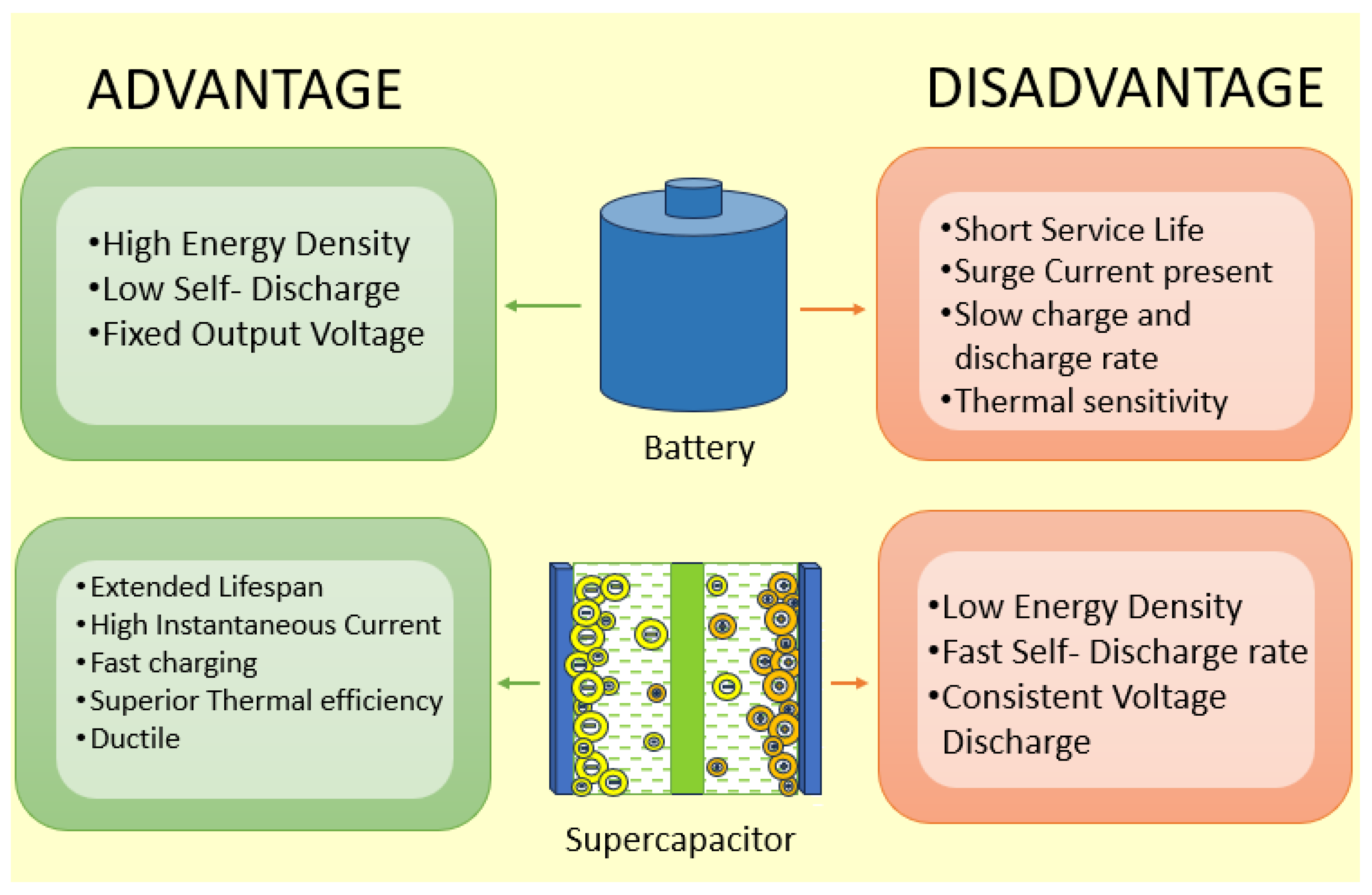
2. Background of Supercapacitors

2.1. Definition

SCs are revolutionary devices, also known as ultra−capacitors or electric double−layer capacitors. They possess fast charging/discharging properties, i.e., they require very little time to charge and dissipate power at approximately the same charging speed. SCs can store a large amount of energy, typically 100 to 1000 times per unit volume or mass, compared to a conventional electrolytic capacitor [25].
The SC shares similarities with a capacitor, except for the following distinctions: a porous material, activated carbon, is used for the electrodes in a SC, which covers a much larger surface area; and the distance between the electrodes is smaller than the conventional capacitor. Both the larger surface area and a smaller distance create a larger electric field, and hence, higher energy storage in SCs. These metal electrode plates are immersed in electrolytes and separated by a thin insulating material. When the electrode plates are charged, an electric double layer forms in the SC, creating opposite charges on each side of the separator. As a result, the SC exhibits higher capacitance. Essentially, the SCs have a higher energy density and better capacitance because of the arrangement of the plates and their increased specific surface area, which is caused by the roughness and porosity of the electrode material, which is usually carbonaceous. Unlike batteries, SCs have an unlimited lifespan and experience minimal degradation with prolonged use. Hence, they can undergo charging and discharging an unlimited number of times [25].
SCs are also more effective on various factors than Li−ion batteries [25]. SCs are highly efficient energy storage devices that bridge the gap between battery−powered systems and bulk capacitors. They can handle higher charge and discharge rates than rechargeable batteries, making them excellent for short−term energy storage [26], and have a long life and are able to work in a wide range of temperatures. Figure 1 summarizes the differences between Li−ion batteries and SCs, briefly mentioning their pros and cons.

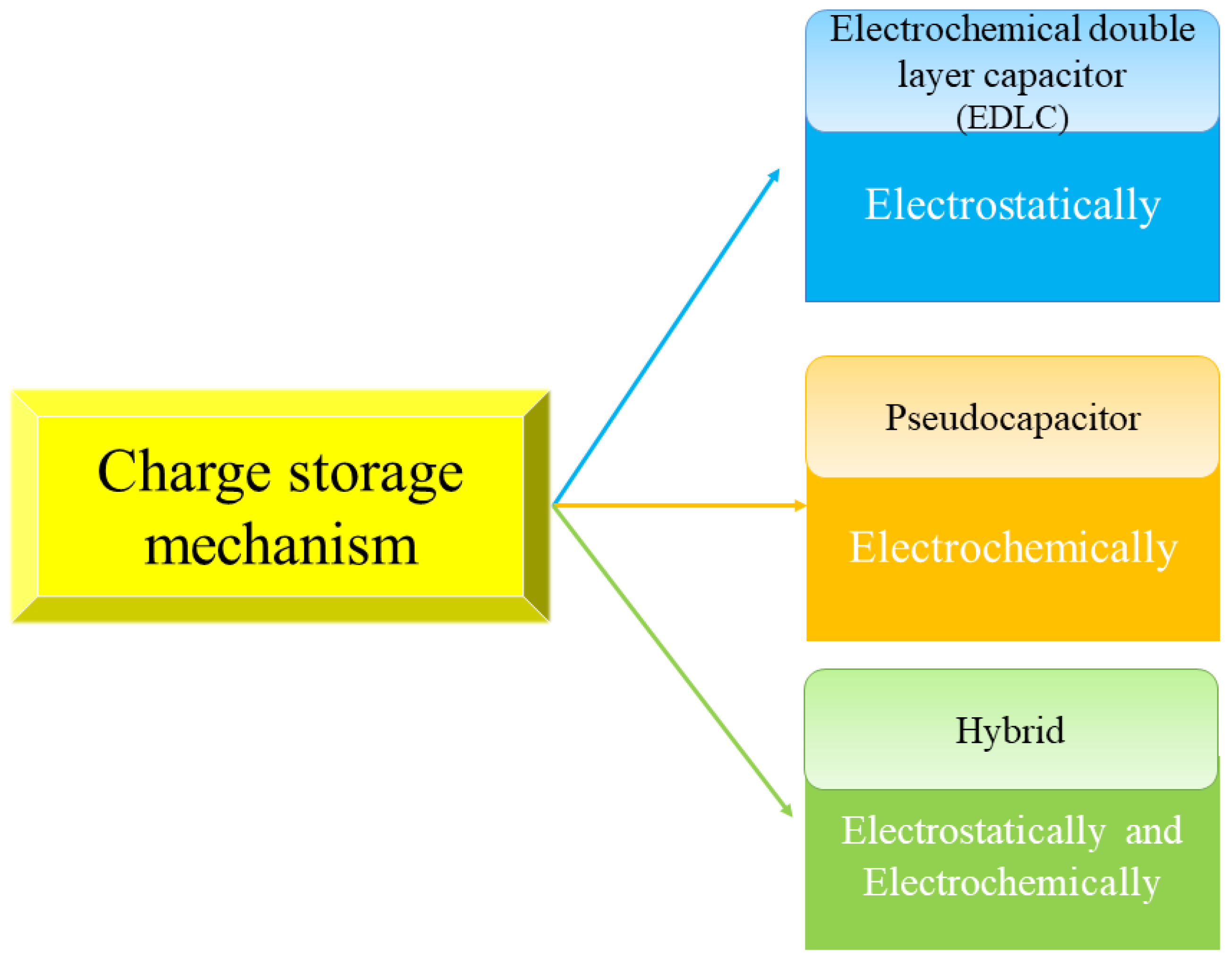
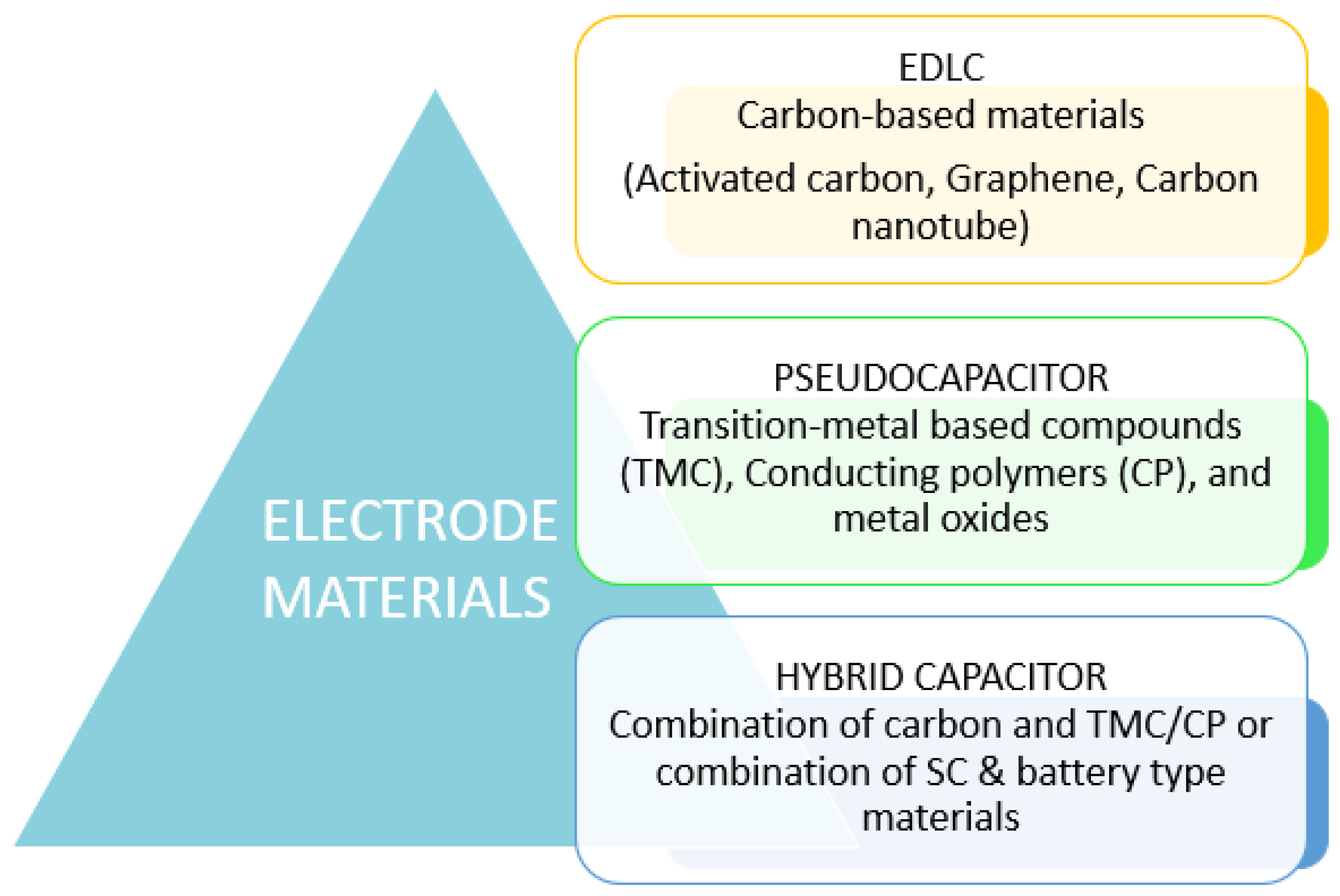
2.2. Types of Supercapacitors

As shown in Figure 2, SCs are broadly classified into three categories based on the storage principle and material of the electrode [28], namely, electrochemical double−layer capacitors (EDLCs), pseudocapacitors, and hybrid. Hybrid SCs are a combination of EDLCs and pseudocapacitors. Initially, all electrochemical capacitors were called “double−layer capacitors”, but they are now part of a larger family called SCs.
Figure 3 shows the major difference in the charge storing mechanism in the three types of SCs. Double−layer capacitance is the electrostatic storage of electrical energy in EDLCs, achieved by charge separation in a Helmholtz double layer at the interface between a conductor electrode and an electrolytic solution electrolyte. On the other hand, pseudocapacitance is the electrochemical storage of electrical energy in pseudocapacitors, achieved through redox reactions, electrosorption, or intercalation on electrode surfaces, resulting in a reversible faradaic charge transfer [28].
Figure 4 shows the major difference in electrode materials in the three types of SCs [30].
SCs rely heavily on electrolytes to transfer and balance charges between electrodes. These are divided into several groups, and their interaction with electrodes has a substantial impact on the interface state and internal structure of active materials. Figure 5 shows the different types of electrolytes used in SCs [31]. The electrolyte used in supercapacitive devices is critical from the point of view of safety and performance. There is no perfect electrolyte that meets all needs. Aqueous electrolytes have high conductivity and capacitance but low energy density, low cycling stability, and leakage issues. To solve these difficulties, hybrid electrolytes like acetonitrile were developed. Finding suitable electrolytes is critical for developing safe and efficient supercapacitive devices. Figure 6 shows the effects of electrolytes on the SC performance [32,33,34]. The authors in [35] have extensively studied the charge storage mechanisms in different types of SCs, including hybrid capacitors. Their research provides valuable insights into the electrostatic and electrochemical processes involved in these devices [35,36].

2.2.1. Electrochemical Double−Layer Capacitors

EDLCs generally comprise two activated carbon−based materials which are used as porous electrodes. Furthermore, an electrolyte and a separator are used to isolate the two electrodes electrically. EDLCs can store charge electrostatically with a non−faradaic process (i.e., the charge does not travel between the electrode and the electrolyte). Because it is primarily a function of the electrode surface area, the charge stored per unit voltage in a supercapacitor increases as a result of the porous electrode material.
Generally speaking, capacitance and specific energy increase with decreasing electrode pore size. While smaller electrode pores result in higher specific energy and capacitance, they also increase equivalent series resistance (ESR) and lower specific power. Larger pores and reduced internal losses are necessary for applications with high peak currents [28,37].
In EDLCs, the charge accumulates on the surface of electrodes when a voltage is applied to the electrode terminals, as shown in Figure 7. The potential difference between these electrodes causes opposite charges to attract. Consequently, the electrolyte ions diffuse across the separator and into the pores of the oppositely charged electrode. Hence, an electric double−charge layer is established at the electrodes to prevent ion recombination. This double layer, the expanded specific surface area, and the reduced electrode distances enable EDLCs to achieve higher energy density [38].
When compared to conventional capacitors, EDLCs perform better overall because of their faster charging and discharging times due to their electrostatic storing method. Furthermore, because EDLCs use a non−faradaic mechanism with no chemical reactions, the problem of active material swelling in batteries from charging and discharging is eliminated to an extent in EDLCs. As a result, the swelling phenomenon of SC electrodes is present to a lesser extent [40].
With further analysis of the working of EDLCs, one can easily conclude that the number of charging−discharging cycles that EDLCs can withstand is approximately a thousand times that of a battery. This is mainly because there is no conversion of energy. Unlike batteries, SCs do not convert electrical energy to chemical energy, eliminating conversational power losses.

2.2.2. Pseudocapacitors

Pseudocapacitors exhibit superior energy densities compared to EDLCs. Contrary to EDLCs, pseudocapacitors store charge through a faradaic process that involves various chemical reactions. Therefore, the charge moves between the electrode and the electrolyte [41].
Figure 8 shows the transfer of electron charges between the electrode and the electrolyte. Reactions, intercalation, electrosorption, reduction−oxidation, and other mechanisms contribute to this electrochemical storage process. These reactions cause the charge to flow across the double layer, generating a faradaic current traversing the SC cell. High electrochemical pseudocapacitance, proportional to the applied voltage, is a defining characteristic of pseudocapacitors. They are composed of metal oxides with high electrochemical pseudocapacitance or conductive polymer electrodes. Materials such as conducting polymers, metal hydroxides, metal sulphides, metal nitrides, and metal oxides frequently employ pseudocapacitor electrodes. These materials raise energy densities, enabling higher power storage densities. The faradaic method improves electrochemical processes, raising specific capacitance and energy densities in pseudocapacitors. While pseudocapacitors benefit from the higher energy density achieved through these chemical processes, they face certain drawbacks such as a lower number of charging−discharging cycles and poorer power density. Despite these shortcomings, pseudocapacitors find applications in wearable electronics, consumer electronics, wind turbines, cranes, lifts, and in−car applications such as regenerative braking [42].

2.2.3. Hybrid

Pseudocapacitive, battery−type, and EDLC materials are used to create hybrid SCs. They are made up of an electric double−layer electrode in an organic or fluid electrolyte, with a redox reaction or battery−type electrode. Figure 9 shows the charge storage mechanism in a hybrid capacitor. Similar to EDLC, the positive electrode achieves storage by double−layer capacitance. Charges are accumulated as a result of a redox reaction occurring on the negative electrode containing the active redox molecules. Pseudocapacitors and this method are comparable in terms of charge storage [43].
When used in combination, a hybrid system combines the advantageous features of both EDLCs and pseudocapacitors, providing a blend of desirable properties. This offers excellent cyclic stability, impressive power performance, and enhanced specific capacitance. Furthermore, hybrid SCs can boost both energy and power densities without sacrificing system stability. This is accomplished by integrating a battery−like electrode, serving as the energy source, with a capacitor−like electrode, functioning as the power source, within the same cell.
By employing an appropriate combination of electrodes, it becomes feasible to increase the cell voltage, consequently enhancing both energy and power densities. Interested readers can find recent advances in hybrid SCs, their design and fabrication, in [44], and about electrodes and electrolytes in [45].

2.3. Differences between Supercapacitors and Capacitors

The main function of capacitors and SCs is to store electric charge through electrostatic means, making them passive components. However, there exist differences between a capacitor and a SC.
SCs are like regular capacitors, except they can hold a greater charge, which means they can store much more energy. For example, for the EPCOS B43644 series or Nichicon’s 560 μF, a 200 V aluminum electrolytic capacitor, the energy stored in the capacitor is 11.2 J, based on the formula given by Equation (1):
E = 0.5 C V 2 ,
where E signifies energy stored in the capacitor (in joules, J), C is the capacitance (in farads, F), and V is the rated voltage (in volts, V). On the other hand, for a Maxwell Technologies BCAP0010 SC, with a nominal capacitance of 2600 F and a rated voltage of 2.5 V, the amount of energy that can be stored is 8.125 kJ [3].
While all capacitors have voltage limitations, electrostatic capacitors can be designed to withstand high voltages. On the contrary, SCs have a narrower voltage range and are typically confined to operating within the range of 2.5−2.7 V. Furthermore, Table 1 compares the energy storage capacities of SCs and capacitors. The rated voltage of SCs is significantly lower compared to traditional capacitors due to the differences in their design, materials, and mechanisms of energy storage. Traditional capacitors use dielectric materials like ceramics, aluminum oxide, or polymers between their electrodes. The dielectric materials can withstand higher electric fields without breaking down, allowing traditional capacitors to have much higher voltage ratings, often in the range of hundreds of volts.
Table 2 lists all the major key differences between a SC and a capacitor (see [46] and references therein). The most significant difference between a capacitor and a SC is that a SC has high capacitance value and low voltage rating, whereas a capacitor has low capacitance value and high voltage rating.

3. Equivalent Circuits

SCs have various benefits, such as:
  • The ability to produce high power and support high load currents due to their low resistance.
  • Their charging system is easy to use, quick, and resistant to overcharging.
  • SCs have superior high− and low−temperature charge and discharge performance compared to batteries.
  • They offer low impedance and are very dependable.
SCs, however, have several drawbacks, such as their expensive price and the significant self−discharge involved. They also have lower specific energies than typical batteries; linear discharge voltage prevents it from using the entire energy spectrum [25]. Further, [6] describes the merits and demerits of SCs in practical applications.
The criteria for modeling the different equivalent circuits of SCs depends upon the frequency, voltage, and temperature dependencies of capacitance, series resistance, redistribution of electrical charges on the electrode surface, and leakage current. Parameters were generally determined by studying the performance on charge/discharge cycles. The general idea for selecting different combinations of R, L, and C during modeling SCs is as follows [47]:
  • An equivalent RC transmission line behavior, which characterizes the dynamic response of SCs, is particularly evident in the frequency range of 0.1 Hz to 10 Hz. This behavior is a result of the porous nature of the capacitive interface.
  • A self−discharge that can be represented by a high−value resistor in parallel, known as a leakage resistor.
  • A phenomenon of charge redistribution that happens at low frequencies or during charge and discharge cycles longer than 1 min. It is described through two RC branches with long constant times, which are longer compared to the constant time of the RC transmission line.
  • A resonance frequency (below 200 Hz) points to the transition from capacitive to inductive impedance characteristics and is identified by the impedance real part’s minimum. Beyond this resonance frequency; there is an observed increase in the minimum value of the real part of the impedance with frequency, showcasing inductive behavior.
Based on the above discussion, the basic idea is to analyze EECs formulated using basic electrical components: resistors, capacitors, and inductors, to model the voltage−current response of SCs to combine the qualities of SCs without having their limitations. The EECs proposed in [5] and references within are further analyzed in the following sections. As capacitors and SCs operate on alternating current (AC), expressing resistance to the flow of this current becomes extremely important, hence equivalent impedance is computed for each EEC model.
The notation used to illustrate the components (such as resistors, inductors, and capacitors) used in the circuit is standard notation supported by suffixes. For example, C v a r describes the variable capacitor. The ω denotes the angular frequency. An equivalent series resistor (ESR) represents the ohmic losses and an equivalent parallel resistor (EPR) represents the SC self−discharge.

3.1. Circuit 1

The circuit, as shown in Figure 10, is a three−parallel RC branched electrical circuit [5,48]. It is worth mentioning here that each branch taken here has a different time constant. The model’s structure was developed based on the following basic concepts related to the double layer: two−material−interface electrochemistry, interfacial tension, and self−discharge. The equivalent impedance Z of the circuit is calculated as shown in Equation (2):
Z = j ω R i X C i o + C v a r + X j ω R i ( C i o + C v a r ) + j ω X ( C i o + C v a r ) + 1 ,
where X is given by Equation (3) as:
X = R f R i 1 / ω 2 C d C i + 1 / j ω ( R f / C i + R i / C d ) ( R f + R i ) + 1 / j ω ( 1 / C d + 1 / C i ) .

3.2. Circuit 2

To model the behavior of the EDLCs, a ladder electrical circuit is used, which is shown in Figure 11 [5,49,50]. The equivalent circuit parameters were selected experimentally utilizing AC inputs through non−linear least square adjustments. The ladder circuits and the EEC were compared in two situations (slow discharge and pulse load) to evaluate their performance [5]. It was noted that for ladder circuits when the number of RC branches rises and the current decays more quickly than it does in the EEC, the simulated voltages shift in favor of the real voltage. The equivalent impedance Z of this EEC is computed as described in following Equation (4):
Z = α R L + α R 1 + R 1 R L α + R L ,
and α is given by Equation (5):
α = R 2 R n 1 ω 2 C n C 2 + 1 j ω R n C 2 + R 2 C n + R 2 C 2 R n + 1 j ω 1 C n + 1 C 2 1 j ω C 1 R 2 R n 1 ω 2 C n C 2 + 1 j ω R n C 2 + R 2 C n + R 2 C 2 R n + 1 j ω 1 C n + 1 C 2 + 1 j ω C 1 .

3.3. Circuit 3

The two−branched RC model shown in Figure 12 is a simpler EEC developed in [5,51] for faster parameter determination. This circuit is easy to use because only four measurements are required from the terminals of the device, two voltage measurements during the charging process, the first before reaching the rated voltage and the second after several minutes, and some algebraic equations (KCL and KVL) that use these measurements. The voltage drops when a charging current is applied. A comparison was between the three−branched RC model and the two−branched proposed model by the authors to demonstrate the novelty of this model which reproduces the dynamic response better than the three−branched model. The equivalent impedance Z of the circuit in Figure 12 is mathematically modeled in Equation (6):
Z = R o + 1 j ω C o + C v a r R p + j ω R 2 C 2 R p 1 + j ω R p C 2 + R 2 C 2 R o + 1 j ω C o + C v a r + R p + j ω R 2 C 2 R p 1 + j ω R p C 2 + R 2 C 2 .
In the same way, the authors of [52] created a model with very little computing cost. Therefore, this is a quick method for figuring out the characteristics of an electric circuit with three branches of RC, with a focus on the components of the first branch and the escape resistance.

3.4. Circuit 4

The previous two EECs offer good performance at very low frequencies only; therefore, to enable SCs at high frequencies an equivalent circuit called the dynamic model was proposed in [5,20,53] and is shown in Figure 13. This EEC, developed by the impedance spectroscopy methodology, enables the reproduction of the SC’s transient behavior over a wide frequency range. The equivalent impedance Z of this equivalent circuit is determined by Equation (7):
Z = j ω L f + R h f + 1 j ω C i f + R 1 1 + j ω C 1 R 1 + R n 1 + j ω C n R n .

3.5. Circuit 5

Another EEC structure was presented in [5] and references within, called the complete model, as depicted in Figure 14. The behavior of the SC in both constant and transient states across a broad frequency range can be accurately modeled using this model. Another benefit of this EEC, as highlighted by the authors, is that the parameters were calculated using a datasheet provided by the manufacturer and the results of a constant charging current test. Furthermore, as the complete model can more accurately reproduce the voltage response of SCs, it is suitable for applications involving high and low dynamic frequency cycles. The equivalent impedance Z of this circuit is given by Equation (8):
Z = β R l e a k + j ω C 2 R 2 R l e a k R l e a k + j ω C 2 R 2 R l e a k + β 1 + j ω C 2 R l e a k + R 2 ,
where β is determined by Equation (9):
β = R i + 1 j ω C ( v ) + R 1 j ω C ( v ) R 1 2 + 1 + R i n j ω C ( v ) R i n 2 + 1 .

3.6. Circuit 6

The authors of [54] constructed an EEC with two branches to mimic the behavior of a SC and proposed a novel approach to estimate the parameters. The model considers the physical phenomena occurring at the interface between the electrode and the electrolyte. It utilizes the assumption that ions not only adhere to the electrodes but also diffuse into the nearby region of the electrolyte in contact with the electrode. As in [5], there are two capacitors: the diffusion capacitance is represented by one of the capacitors, while the Helmholtz capacitance is represented by the other. And there are three resistors among the EEC’s five components. These three include the equivalent series resistance, leakage resistance, and the third resistance is in between the first two and is time−dependent. Further, [5] exhibits the equations for determining the parameters of all the EEC models discussed so far. The equivalent impedance Z of the EEC shown in Figure 15 is given by Equation (10):
Z = γ + R 1 ,
where γ is described by Equation (11):
γ = R L + j ω C 2 R L R 2 ( t ) 1 + j ω C 2 R L + R 2 ( t ) 1 j ω C 1 R L + j ω C 2 R L R 2 ( t ) 1 + j ω C 2 R L + R 2 ( t ) + 1 j ω C 1 .

3.7. Circuit 7

The EEC shown in Figure 16 explains how the SC responds to the parameters such as frequency, voltage, and temperature. The EEC, shown in Figure 16, consists of 14 RLC elements. Three circuits are distinguished in this EEC [3]: the first allows for the low−frequency consideration of the temperature’s impact on the electrolyte ion resistance; the second increases the capacitance value; and the third denotes both the leakage current and the redistribution of the internal load in the SC. The equivalent impedance Z of this circuit is as shown in Equation (12):
Z = W R L W + R L ,
where W is given by Equation (13):
W = ϕ + j ω C p 1 R p 1 ϕ 1 + j ω C p 1 R p 1 + ϕ R p 2 + 1 j ω C p 2 ϕ + j ω C p 1 R p 1 ϕ 1 + j ω C p 1 R p 1 + ϕ + R p 2 + 1 j ω C p 2 ,
ϕ is described by Equation (14):
ϕ = δ + j ω C r R i δ + R e + j ω L 1 + j ω C r R i + δ 1 + j ω C r R i + δ ,
and δ is given by Equation (15):
δ = R v j ω C o 1 ω 2 C v C o R v + 1 j ω 1 C v + 1 C o + R i 1 + j ω C i R i .

3.8. Circuit 8

As mentioned in [55] and shown in Figure 17, this EEC consists of a capacitor, an equivalent series resistance, and an equivalent parallel resistance. Through analysis of the performance during charge/discharge cycles, the parameters were established. The equivalent impedance Z of this circuit is described by Equation (16):
Z = R s + R p 1 + j ω C R p .

3.9. Circuit 9

In [55], the authors presented two similar circuits in 2008, one with an RC series—parallel and the other with a transmission line made of RC circuitry. This EEC, a model of the Maxwell BCAP350 SC [56], is the first one among these two; as shown in Figure 18, a resistance and capacitor are in series with two parallel RC circuit connections. The equivalent impedance Z of this circuit is calculated as shown by Equation (17):
Z = R s + 1 j ω C s + R 1 1 + j ω C 1 R 1 + R 2 1 + j ω C 2 R 2 .

3.10. Circuit 10

The EEC shown in Figure 19 is the second RC−circuit−type transmission line EEC proposed in [55]. The equivalent impedance Z of this EEC, consisting of three RC circuit branches in parallel, is given by Equation (18):
Z = σ 1 + j ω C 1 σ + R 1 ,
where σ is given by Equation (19):
σ = R 3 + 1 j ω C 3 1 j ω C 2 R 3 + 1 j ω C 3 + 1 j ω C 2 + R 2 .

3.11. Circuit 11

In [55], the authors analyzed another EEC for SCs, shown in Figure 20. In this circuit, a resistor and inductor are in series with an RC parallel circuit. The equivalent impedance Z of this circuit is calculated using Equation (20):
Z = R p 1 + j ω C R p + R c + j ω L c .

3.12. Potential Uses and Benefits of EEC

The mentioned EECs have several benefits, including:
  • Circuit 4 is specifically tailored to assess the energy efficiency of SCs in dynamic environments like mild−hybrid vehicles [53];
  • Circuit 6 is similar to the NessCap 10 F/2.7 V, Maxwell 10 F/2.5 V, and CapXX 2.4 F/2.75 V SCs in terms of capacitance and rated voltage [54];
  • Circuit 7 can be easily used in various analog simulation software [3];
  • Sensitivity analysis of SCs for thermal, frequency, and voltage parameters in automobiles [3].

4. Supercapacitor Applications

The high power density, quick electrical reaction, lack of ongoing maintenance, and ability to operate in a wide variety of temperatures are only a few of the highly special characteristics of SCs. These properties of SCs make them useful in numerous applications like transmitting power and filling power gaps. In some situations, such as those involving battery−free gadgets, they serve as a battery replacement [25].
Numerous products and systems, such as laptops, personal digital assistants (PDAs), Global Positioning System (GPS), portable media players, handheld gadgets [57], and solar systems, also use SCs. They stabilize power supply, deliver power for flashes in digital cameras, and power portable speakers [58]. Although the run time of a cordless electric screwdriver using SCs is reduced to half, it can be fully charged in just 90 s [59].
SCs find extensive use in various industries and research and development institutions. In [19], the authors mentioned the use of SCs in uninterruptible power supplies (UPSs) as they can provide reliable power for critical loads when a power disruption occurs. SCs can replace batteries in critical systems applications because batteries have low power densities and short cycle lives. Moreover, when utility power disruptions occur, the pulsating current leads to battery losses and a decrease in battery cycle life. Therefore, in UPS energy storage, a combination of SCs and rechargeable batteries is proposed in [60] and referred to as a super accumulator module (SAM) in [61]. SCs are an affordable replacement for large banks of electrolytic capacitors for UPS that minimize cycle costs, enable battery downsizing, and increase battery longevity. They reduce brief power outages and high current peaks by buffering power to and from rechargeable batteries [62]. SCs are the only power source for low−energy applications, for example, automated meter reading equipment deployed in advanced metering infrastructure [63]. They also supply backup power for actuators in wind turbine pitch systems and low−power devices like random access memory (RAM), static random access memory (SRAM), microcontrollers, and PC cards.
SCs have a high demand in power electronics and renewable energy systems. The other applications of SCs are in street lights, cranes and forklifts, train lines, railroad locomotives, etc. Figure 21 indicates a few applications of SCs.
Furthermore, SCs are used for various defense applications, such as radars, military vehicles, radio frequency communications, munitions, avionics, etc. All transportation systems face the challenge of reducing fossil fuel consumption and carbon dioxide emissions, and recovering braking energy can help significantly. SCs fill the need in several applications in vehicles for parts that can swiftly store and transfer energy. The “Ultracap Bus”, which underwent testing in Nuremberg, Germany, in 2001, was the first hybrid bus in Europe to utilize SCs, as mentioned in [19].
Some other SC applications are consumer electronics, tools, voltage stabilization, microgrids, energy harvesting, and medical applications. SCs are employed in microgrid storage systems, often powered by renewable energy. Sometimes they cannot meet the power demand and, as a result, the generation falls. Different non−linear loads, such as hybrid electric vehicles, EV chargers in charging stations, air conditioning systems, electrical equipment (inductive load), advanced power conversion systems, and other power systems, can lead to oscillations in the grid’s current and power [64]. These current harmonics and power fluctuations decrease the efficiency of the grid and cause voltage drops in the common coupling points. Further, these frequency fluctuations travel through the entire power system, polluting the grid and causing harm to all connected load devices and generation busses [65]. SCs can serve as an interface between the load and the grid to avoid this problem. This includes SCs acting as a buffer between the grid and the high pulse power drawn from the EV charging station to combat this issue of harmonics and fluctuations in the grid [66,67].
From insights in [6] and references within, it is come to know that for temporary energy storage devices, SCs make good energy harvesting systems. For instance, streetlights in Sado City, Niigata Prefecture, Japan, incorporate isolated SCs and a power supply for storage. Additionally, hybrid SCs can be employed in battery−powered communication, navigation, and sensor systems.

5. Perspectives and Future Scope

SCs are a developing technology with distinctive features. SCs are increasingly finding their way into various applications due to their advantages, such as the capacity to supply abrupt surges of energy. Knowing the various kinds of SCs and how they store energy is crucial to comprehend which SC is best for a given application. For many years now, EECs have been developed and analyzed to learn more about the voltage response of SCs. The analysis now moves on to the impedance parameter, which has not yet been considered. Since all capacitors operate on ACs, impedance analysis was crucial for a better understanding of SCs.
SCs are advanced devices for evaluating sustainable, reliable, and clean energy storage systems, particularly in EVs. These models will serve as diagnostic tools for future generations, as SCs, with their cutting−edge technologies, will play a vital role in the rapid development of new electric cars that will flood the markets in the upcoming years [24]. Researchers also aim to enhance the energy density of electrochemical capacitors for EVs and regenerative energy storage applications. Combining battery and capacitor characteristics in hybrid battery−capacitor electrodes allows for surpassing energy density limitations. However, the challenge lies in effectively managing and harmonizing the redox and double−layer processes. Nevertheless, the successful development of a hybrid device known as a “nanohybrid capacitor” has been achieved by utilizing ultrafast materials [68]. A nanohybrid capacitor is an advanced energy storage device that combines the high power density of SCs with the high energy density of batteries using nanomaterials. An example includes a SC with ultrafast Li4Ti5O12 (LTO) nanocrystal electrodes, which provides rapid charging, high efficiency, and enhanced durability due to optimized “nano−LTO/carbon composites”. Nanohybrid capacitors offer exceptional energy, power, and cyclability performance as compared to Li−ion capacitors. Despite operating at extremely high current densities, nanohybrid capacitors demonstrate improved stability and safety. They exhibit energy density that is more than triple and can be readily scaled up for the production of large volumes of materials, making them suitable for applications in electrochemical energy storage. Nanohybrid SC is an upcoming technology that meets energy demands in microelectronics, EVs, and energy storage devices [68]. As the performance of SCs is significantly affected by the electrode materials and electrolyte properties, upcoming research will focus on advanced materials for SC electrodes for efficient electron transport. To explore further the latest advancements and challenges in SCs, refer to [69,70].

Author Contributions

Conceptualization, P.M. and S.S.; methodology, P.M.; validation, P.M., S.S. and S.B.; formal analysis, P.M. and S.S.; investigation, S.S. and S.B.; resources, P.M. and S.S.; writing—original draft preparation, P.M. and S.S.; writing—review and editing, P.M., S.S. and S.B.; visualization, P.M., S.S. and S.B.; supervision, S.S. and S.B. All authors have read and agreed to the published version of the manuscript.

Funding

This research received no external funding.

Data Availability Statement

Not applicable.

Conflicts of Interest

The authors declare no conflict of interest.

References

  1. Chicco, G. Sustainability challenges for future energy systems. J. Sustain. Energy 2010, 1, 6–16. [Google Scholar]
  2. Hammond, G.P. Engineering sustainability: Thermodynamics, energy systems, and the environment. Int. J. Energy Res. 2004, 28, 613–639. [Google Scholar] [CrossRef]
  3. Rafik, F.; Gualous, H.; Gallay, R.; Crausaz, A.; Berthon, A. Frequency, thermal and voltage supercapacitor characterization and modeling. J. Power Sources 2007, 165, 928–934. [Google Scholar] [CrossRef]
  4. Guney, M.S.; Tepe, Y. Classification and assessment of energy storage systems. Renew. Sustain. Energy Rev. 2017, 75, 1187–1197. [Google Scholar] [CrossRef]
  5. Hidalgo-Reyes, J.; Gómez-Aguilar, J.F.; Escobar-Jiménez, R.F.; Alvarado-Martínez, V.M.; López-López, M. Classical and fractional-order modeling of equivalent electrical circuits for supercapacitors and batteries, energy management strategies for hybrid systems and methods for the state of charge estimation: A state of the art review. Microelectron. J. 2019, 85, 109–128. [Google Scholar] [CrossRef]
  6. Şahin, M.E.; Blaabjerg, F.; Sangwongwanich, A. A Comprehensive Review on Supercapacitor Applications and Developments. Energies 2022, 15, 674. [Google Scholar] [CrossRef]
  7. Queirós, G.; Rey-Raap, N.; Pereira, C.; Pereira, M. CNT-based Materials as Electrodes for Flexible Supercapacitors. U. Porto J. Eng. 2021, 7, 151–162. [Google Scholar] [CrossRef]
  8. Conway, B.E. Electrochemical Supercapacitors: Scientific Fundamentals and Technological Applications; Springer Science & Business Media: Berlin/Heidelberg, Germany, 2013. [Google Scholar]
  9. Frackowiak, E.; Béguin, F. Supercapacitors: Materials, Systems and Applications; Pozn. Wiley-VCH Verlag GmbH Co.: Weinheim, Germany, 2013. [Google Scholar]
  10. Miller, J.R.; Simon, P. Electrochemical capacitors for energy management. Science 2008, 321, 651–652. [Google Scholar] [CrossRef]
  11. Burke, A. Ultracapacitors: Why, how, and where is the technology. J. Power Sources 2000, 91, 37–50. [Google Scholar] [CrossRef]
  12. Karthikeyan, S.; Narenthiran, B.; Sivanantham, A.; Bhatlu, L.D.; Maridurai, T. Supercapacitor: Evolution and review. Mater. Today Proc. 2021, 46, 3984–3988. [Google Scholar] [CrossRef]
  13. Iro, Z.S.; Subramani, C.; Dash, S. A brief review on electrode materials for supercapacitor. Int. J. Electrochem. Sci. 2016, 11, 10628–10643. [Google Scholar] [CrossRef]
  14. Shah, S.S.; Niaz, F.; Ehsan, M.A.; Das, H.T.; Younas, M.; Khan, A.S.; Rahman, H.U.; Nayem, S.A.; Oyama, M.; Aziz, M.A. Advanced strategies in electrode engineering and nanomaterial modifications for supercapacitor performance enhancement: A comprehensive review. J. Energy Storage 2024, 79, 110152. [Google Scholar] [CrossRef]
  15. Perdana, M.Y.; Johan, B.A.; Abdallah, M.; Hossain, M.E.; Aziz, M.A.; Baroud, T.N.; Drmosh, Q.A. Understanding the Behavior of Supercapacitor Materials via Electrochemical Impedance Spectroscopy: A Review. Chem. Rec. 2024, 24, e202400007. [Google Scholar] [CrossRef] [PubMed]
  16. Khan, H.A.; Tawalbeh, M.; Aljawrneh, B.; Abuwatfa, W.; Al-Othman, A.; Sadeghifar, H.; Olabi, A.G. A comprehensive review on supercapacitors: Their promise to flexibility, high temperature, materials, design, and challenges. Energy 2024, 295, 131043. [Google Scholar] [CrossRef]
  17. Reenu; Sonia; Phor, L.; Kumar, A.; Chahal, S. Electrode materials for supercapacitors: A comprehensive review of advancements and performance. J. Energy Storage 2024, 84, 110698. [Google Scholar] [CrossRef]
  18. Poonam; Sharma, K.; Arora, A.; Tripathi, S.K. Review of supercapacitors: Materials and devices. J. Energy Storage 2019, 21, 801–825. [Google Scholar] [CrossRef]
  19. Zhang, L.; Hu, X.; Wang, Z.; Sun, F.; Dorrell, D.G. A review of supercapacitor modeling, estimation, and applications: A control/management perspective. Renew. Sustain. Energy Rev. 2018, 81, 1868–1878. [Google Scholar] [CrossRef]
  20. Devillers, N.; Jemei, S.; Péra, M.C.; Bienaimé, D.; Gustin, F. Review of characterization methods for supercapacitor modelling. J. Power Sources 2014, 246, 596–608. [Google Scholar] [CrossRef]
  21. Catelani, M.; Ciani, L.; Corti, F.; Laschi, M.; Patriz, G.; Reatti, A.; Vangi, D. Experimental characterization of Hybrid Supercapacitor under different operating conditions using EIS Measurements. IEEE Trans. Instrum. Meas. 2023, 73, 1–10. [Google Scholar] [CrossRef]
  22. Yaseen, M.; Khattak, M.A.K.; Humayun, M.; Usman, M.; Shah, S.S.; Bibi, S.; Hasnain, B.S.U.; Ahmad, S.M.; Khan, A.; Shah, N.; et al. A review of supercapacitors: Materials design, modification, and applications. Energies 2021, 14, 7779. [Google Scholar] [CrossRef]
  23. Khalid, M. A review on the selected applications of battery-supercapacitor hybrid energy storage systems for microgrids. Energies 2019, 12, 4559. [Google Scholar] [CrossRef]
  24. Ates, M.; Chebil, A. Supercapacitor and battery performances of multi-component nanocomposites: Real circuit and equivalent circuit model analysis. J. Energy Storage 2022, 53, 105093. [Google Scholar] [CrossRef]
  25. Rouse, M. Supercapacitor. 2015. Available online: https://www.techopedia.com/definition/30407/supercapacitor (accessed on 20 October 2022).
  26. Sengupta, A.S.; Satpathy, S.; Mohanty, S.P.; Baral, D.; Bhattacharyya, B.K. Supercapacitors Outperform Conventional Batteries [Energy and Security]. IEEE Consum. Electron. Mag. 2018, 7, 50–53. [Google Scholar] [CrossRef]
  27. Capacitech Energy. Batteries vs Supercapacitors: The Answer is Both. Capacit. Energy Blog 2023. Available online: https://www.capacitechenergy.com/blog/batteries-vs-supercapacitors-the-answer-is-both (accessed on 10 June 2024).
  28. Namisnyk, A.; Zhu, J. A survey of electrochemical super-capacitor technology. In Proceedings of the Australian Universities Power Engineering Conference; University of Canterbury: Christchurch, New Zealand, 2003. [Google Scholar]
  29. Oyedotun, K. Synthesis and Characterization of Carbon-Based Nanostructured Material Electrodes for Designing Novel Hybrid Supercapacitors. Ph.D. Thesis, University of Pretoria, Hatfield, UK, 2018. [Google Scholar] [CrossRef]
  30. Czagany, M.; Hompoth, S.; Keshri, A.K.; Pandit, N.; Galambos, I.; Gacsi, Z.; Baumli, P. Supercapacitors: An efficient way for energy storage application. Materials 2024, 17, 702. [Google Scholar] [CrossRef] [PubMed]
  31. Pal, B.; Yang, S.; Ramesh, S.; Thangadurai, V.; Jose, R. Electrolyte selection for supercapacitive devices: A critical review. Nanoscale Adv. 2019, 1, 3807–3835. [Google Scholar] [CrossRef] [PubMed]
  32. Pan, Z.; Yang, J.; Kong, J.; Loh, X.J.; Wang, J.; Liu, Z. “Porous and Yet Dense” Electrodes for High-Volumetric-Performance Electrochemical Capacitors: Principles, Advances, and Challenges. Adv. Sci. 2021, 9, 2103953. [Google Scholar] [CrossRef] [PubMed]
  33. Zhong, C.; Yida, D.; Hu, W.; Qiao, J.; Zhang, L.; Zhang, J. A review of electrolyte materials and compositions for electrochemical supercapacitors. Chem. Soc. Rev. 2015, 44, 7431–7920. [Google Scholar] [CrossRef] [PubMed]
  34. Jalal, N.; Ibrahim, R.; Kadhim, M. A review on Supercapacitors: Types and components. J. Phys. Conf. Ser. 2021, 1973, 012015. [Google Scholar] [CrossRef]
  35. Minakshi, M.; Wickramaarachchi, K. Electrochemical aspects of supercapacitors in perspective: From electrochemical configurations to electrode materials processing. Prog. Solid State Chem. 2023, 69, 100390. [Google Scholar] [CrossRef]
  36. Watcharatharapong, T.; Minakshi Sundaram, M.; Chakraborty, S.; Li, D.; Shafiullah, G.; Aughterson, R.D.; Ahuja, R. Effect of transition metal cations on stability enhancement for molybdate-based hybrid supercapacitor. ACS Appl. Mater. Interfaces 2017, 9, 17977–17991. [Google Scholar] [CrossRef] [PubMed]
  37. Celzard, A.; Collas, F.; Marêché, J.; Furdin, G.; Rey, I. Porous electrodes-based double-layer supercapacitors: Pore structure versus series resistance. J. Power Sources 2002, 108, 153–162. [Google Scholar] [CrossRef]
  38. Sharma, P.; Bhatti, T. A review on electrochemical double-layer capacitors. Energy Convers. Manag. 2010, 51, 2901–2912. [Google Scholar] [CrossRef]
  39. Wang, C.; Zhou, E.; He, W.; Deng, X.; Huang, J.; Ding, M.; Wei, X.; Liu, X.; Xu, X.J. NiCo2O4-Based Supercapacitor Nanomaterials. Nanomaterials 2017, 7, 41. [Google Scholar] [CrossRef] [PubMed]
  40. Sharma, S.; Chand, P. Supercapacitor and Electrochemical Techniques: A Brief Review. Results Chem. 2023, 5, 100885. [Google Scholar] [CrossRef]
  41. Prasankumar, T.; Jose, J.; Jose, S.; Balakrishnan, S.P. Pseudocapacitors. In Supercapacitors for the Next Generation; IntechOpen: London, UK, 2021. [Google Scholar]
  42. Everything You Need to Know about Pseudocapacitor. Available online: https://www.icrfq.net/pseudocapacitor/ (accessed on 5 February 2024).
  43. Hybrid Supercapacitor. Available online: https://www.sciencedirect.com/topics/materials-science/hybrid-supercapacitor (accessed on 5 February 2024).
  44. Muzaffar, A.; Ahamed, M.B.; Deshmukh, K.; Thirumalai, J. A review on recent advances in hybrid supercapacitors: Design, fabrication and applications. Renew. Sustain. Energy Rev. 2019, 101, 123–145. [Google Scholar] [CrossRef]
  45. Halper, M.S.; Ellenbogen, J.C. Supercapacitors: A Brief Overview; The MITRE Corporation: McLean, VA, USA, 2006; Volume 1. [Google Scholar]
  46. Saini, M.K. Difference between Capacitor and Supercapacitor. 2022. Available online: https://www.tutorialspoint.com/difference-between-capacitor-and-supercapacitor#:~:text=The%20electrodes%20of%20a%20capacitor,of%20activated%20carbon%20coated%20electrodes.&text=The%20electrical%20energy%20in%20a,electrostatically%20or%20electrochemically%20or%20hybrid (accessed on 29 October 2022).
  47. Lajnef, W.; Vinassa, J.M.; Briat, O.; Azzopardi, S.; Woirgard, E. Characterization methods and modelling of ultracapacitors for use as peak power sources. J. Power Sources 2007, 168, 553–560. [Google Scholar] [CrossRef]
  48. Zubieta, L.; Bonert, R. Characterization of double-layer capacitors for power electronics applications. IEEE Trans. Ind. Appl. 2000, 36, 199–205. [Google Scholar] [CrossRef]
  49. Nelms, R.; Cahela, D.; Tatarchuk, B.J. Modeling double-layer capacitor behavior using ladder circuits. IEEE Trans. Aerosp. Electron. Syst. 2003, 39, 430–438. [Google Scholar] [CrossRef]
  50. Logerais, P.O.; Camara, M.; Riou, O.; Djellad, A.; Omeiri, A.; Delaleux, F.; Durastanti, J. Modeling of a supercapacitor with a multibranch circuit. Int. J. Hydrogen Energy 2015, 40, 13725–13736. [Google Scholar] [CrossRef]
  51. Faranda, R. A new parameters identification procedure for simplified double layer capacitor two-branch model. Electr. Power Syst. Res. 2010, 80, 363–371. [Google Scholar] [CrossRef]
  52. Nikkhoo, M.; Farjah, E.; Ghanbari, T. A simple method for parameters identification of three branches model of supercapacitors. In Proceedings of the 2016 24th Iranian Conference on Electrical Engineering (ICEE), Shiraz, Iran, 10–12 May 2016; pp. 1586–1590. [Google Scholar]
  53. Buller, S.; Karden, E.; Kok, D.; De Doncker, R. Modeling the dynamic behavior of supercapacitors using impedance spectroscopy. In Proceedings of the Conference Record of the 2001 IEEE Industry Applications Conference, 36th IAS Annual Meeting (Cat. No. 01CH37248), Chicago, IL, USA, 30 September–4 October 2001; Volume 4, pp. 2500–2504. [Google Scholar]
  54. Sedlakova, V.; Sikula, J.; Majzner, J.; Sedlak, P.; Kuparowitz, T.; Buergler, B.; Vasina, P. Supercapacitor equivalent electrical circuit model based on charges redistribution by diffusion. J. Power Sources 2015, 286, 58–65. [Google Scholar] [CrossRef]
  55. Dănilă, E.; Lucache, D.D.; Livin, G. Models and modelling the supercapacitors for a defined application. Ann. Univ. Craiova-Electr. Eng. Ser. 2011, 35, 200–205. [Google Scholar]
  56. Wu, C.; Hung, Y.; Hong, C. On-line supercapacitor dynamic models for energy conversion and management. Energy Convers. Manag. 2012, 53, 337–345. [Google Scholar] [CrossRef]
  57. Njema, G.G.; Ouma, R.B.O.; Kibet, J.K. A review on the recent advances in battery development and energy storage technologies. J. Renew. Energy 2024, 2024, 2329261. [Google Scholar] [CrossRef]
  58. Ridden, P. Helium Bluetooth speakers powered by supercapacitors. New Atlas, 27 November 2013. [Google Scholar]
  59. Available online: https://hardware.slashdot.org/story/08/12/10/1821208/ultracapacitor-led-flashlight-charges-in-90-seconds (accessed on 5 February 2024).
  60. Lahyani, A.; Venet, P.; Guermazi, A.; Troudi, A. Battery/supercapacitors combination in uninterruptible power supply (UPS). IEEE Trans. Power Electron. 2012, 28, 1509–1522. [Google Scholar] [CrossRef]
  61. Schneuwly, A.; Gallay, R. Properties and applications of supercapacitors from the state-of-the-art to future trends. In Proceedings of the PCIM, Nuremberg, Germany, 7–8 July 2000; Volume 2000. [Google Scholar]
  62. Stepanov, A.; Galkin, I. Development of supercapacitor based uninterruptible power supply. In Proceedings of the 4th International Symposium “Topical Problems in the Field of Electrical and Power Engineering”, Estonia, Kuressaare, 15–20 January 2007. [Google Scholar]
  63. Murat, Ş.; Ercan, S.Ü.; Dalkın, A.; Ayvaz, E. The use of supercapacitor in smart metering gateway. Int. J. Energy Appl. Technol. 2021, 8, 53–59. [Google Scholar]
  64. Mangaraj, M.; Panda, A.K.; Penthia, T. Supercapacitor supported DSTATCOM for harmonic reduction and power factor correction. In Proceedings of the 2016 IEEE Students’ Conference on Electrical, Electronics and Computer Science (SCEECS), Bhopal, India, 5–6 March 2016; pp. 1–6. [Google Scholar]
  65. Farhadi, M.; Mohammed, O.A. Real-time operation and harmonic analysis of isolated and non-isolated hybrid DC microgrid. IEEE Trans. Ind. Appl. 2014, 50, 2900–2909. [Google Scholar] [CrossRef]
  66. Farhadi, M.; Mohammed, O. Adaptive energy management in redundant hybrid DC microgrid for pulse load mitigation. IEEE Trans. Smart Grid 2014, 6, 54–62. [Google Scholar] [CrossRef]
  67. Farhadi, M.; Mohammed, O.A. Performance enhancement of actively controlled hybrid DC microgrid incorporating pulsed load. IEEE Trans. Ind. Appl. 2015, 51, 3570–3578. [Google Scholar] [CrossRef]
  68. Naoi, K.; Naoi, W.; Aoyagi, S.; Miyamoto, J.i.; Kamino, T. New generation “nanohybrid supercapacitor”. Accounts Chem. Res. 2013, 46, 1075–1083. [Google Scholar] [CrossRef] [PubMed]
  69. Raza, W.; Ali, F.; Raza, N.; Luo, Y.; Kim, K.H.; Yang, J.; Kumar, S.; Mehmood, A.; Kwon, E.E. Recent advancements in supercapacitor technology. Nano Energy 2018, 52, 441–473. [Google Scholar] [CrossRef]
  70. Jiale Sun, B.L.; LRaza, H. A Review on the Conventional Capacitors, Supercapacitors, and Emerging Hybrid Ion Capacitors: Past, Present, and Future. Adv. Energy Sustain. Res. 2022, 3, 2100191. [Google Scholar]
Figure 1. Advantagesand disadvantages of battery and supercapacitor [27].
Wevj 15 00332 g001
Figure 2. Classification of supercapacitors.
Wevj 15 00332 g002
Figure 3. Charge storage mechanism in different types of supercapacitors [29].
Wevj 15 00332 g003
Figure 4. Electrode materials in different types of supercapacitors [30].
Wevj 15 00332 g004
Figure 5. Classification of electrolytes for supercapacitors [31].
Wevj 15 00332 g005
Figure 6. Factors of electrolyte affecting the performance of supercapacitor [32].
Wevj 15 00332 g006
Figure 7. Schematic diagram of electrochemical double−layer capacitors [34,39].
Wevj 15 00332 g007
Figure 8. Schematic illustration of pseudocapacitor [34,39].
Wevj 15 00332 g008
Figure 9. Mechanism of hybrid supercapacitors [34,39].
Wevj 15 00332 g009
Figure 10. Three−parallel RC branched equivalent circuit [5].
Wevj 15 00332 g010
Figure 11. Ladder equivalent circuit [5].
Wevj 15 00332 g011
Figure 12. Two−RC branched equivalent circuit [5].
Wevj 15 00332 g012
Figure 13. Dynamic model [5,53].
Wevj 15 00332 g013
Figure 14. Complete model [5].
Wevj 15 00332 g014
Figure 15. Two−branched equivalent circuit [5,54].
Wevj 15 00332 g015
Figure 16. Fourteen−RLC−element equivalent circuit [3].
Wevj 15 00332 g016
Figure 17. Two equivalent resistances and a capacitor circuit [55].
Wevj 15 00332 g017
Figure 18. RC series−parallel equivalent circuit [55].
Wevj 15 00332 g018
Figure 19. Transmission−line−type equivalent circuit [55].
Wevj 15 00332 g019
Figure 20. Equivalent circuit having an inductor in series with RC circuit [55].
Wevj 15 00332 g020
Figure 21. Some SC applications.
Wevj 15 00332 g021
Table 1. Energy storage capacities of supercapacitors and capacitors.
SpecificationUnitSupercapacitorCapacitor
CapacitanceF2600 5.6 × 10 4
Rated VoltageV2.5200
Maximum Energy StorageJ812511.2
Table 2. Differences between supercapacitors and capacitors.
Basis of DifferenceSupercapacitorCapacitor
DefinitionA SC is a type of capacitor that can hold charge and has a low voltage rating and high capacitance.Electrical energy can be stored as electrostatic charge in a capacitor, a passive circuit component.
Constructional featuresTo create a SC, two conducting plates are separated by an electrolytic solution as an alternative to a dielectric.A dielectric material is used to separate two conducting plates to create a capacitor.
ElectrodesElectrodes with activated carbon coating are present in a SC.A metallic conductor makes up a capacitor’s electrodes.
Energy storage mechanismElectrochemically, electrostatically, or in a hybrid fashion, a SC stores electrical energy.A capacitor can only store electrical energy electrostatically.
Dielectric materialsActivated carbon is used as a SC’s interlayer between its electrodes. A double electric field is generated when an electric field is applied to the material; this double electric field serves as the SC’s dielectric.Ceramics, polymers, mica, paper, aluminum oxides, and other materials are frequently used as capacitor dielectrics.
TypesElectrostatic double−layer capacitors, electrochemical pseudocapacitors, and hybrid SCs are three different types of SCs.The most popular types of capacitors include electrolytic capacitors, film capacitors, paper capacitors, ceramic capacitors, etc., depending on the dielectric material chosen.
Capacitance value (F/g)Typically 10–100 F/g, depending on the material and construction.Much lower, typically in the range of nF to μF per gram.
Voltage ratingThe voltage ratings of SCs are considerably lower.An effective capacitor has a high voltage rating.
Energy density (in Wh/kg)SCs have a very high energy density in comparison. Typically falls between 1 Wh/kg and 10 Wh/kg [3].An electrical capacitor has a low energy density. Typically ranges from 0.01 to 0.05 Wh/kg i.e., <0.1 Wh/kg [3].
Power density (in Wh/kg)SCs have power density of 10,000 Wh/kg [3].Capacitors have power density of more than 1,000,000 Wh/kg, which is much higher than SCs [3].
Time for charging and dischargingDepending on the SC, charging and discharging can take seconds or milliseconds. Roughly around 1–30 s [3].A capacitor can charge or discharge between picoseconds and milliseconds approximately between 10 3 and 10 6 s [3].
Charging and discharging efficiencyFrom 0.85 to 0.98 [3].More than 0.95 [3].
Temperature of operating conditionSCs typically operate between −40 °C and +85 °C.The operating temperature range for a capacitor is roughly −20 °C to +100 °C.
Lifetime (in cycle number)SCs have a life of 10 6 cycles [3].Capacitors also have an average life of 10 6 cycles [3].
Form factorThe form factor of SCs is minimal.Capacitor form factors range from low to high.
CostSCs are expensive.Capacitors cost less.
ApplicationsSCs are frequently used in digital camera LED flashlights, UPS, RAM, CMOS, laptops, and other portable devices to stabilize the power supply.Capacitors are used in power factor correction, filter circuits, signal coupling and decoupling, motor starter circuits, oscillators, etc.
Disclaimer/Publisher’s Note: The statements, opinions and data contained in all publications are solely those of the individual author(s) and contributor(s) and not of MDPI and/or the editor(s). MDPI and/or the editor(s) disclaim responsibility for any injury to people or property resulting from any ideas, methods, instructions or products referred to in the content.

