Abstract
Considering environmental concerns, electric vehicles (EVs) are gaining popularity over conventional internal combustion (IC) engine-based vehicles. Hybrid energy-storage systems (HESSs), comprising a combination of batteries and supercapacitors (SCs), are increasingly utilized in EVs. Such HESS-equipped EVs typically outperform standard electric vehicles. However, the effective management of power sources to meet varying power demands remains a major challenge in the hybrid electric vehicles. This study presents the development of a MATLAB Simulink model for a hybrid energy-storage system aimed at alleviating the load on batteries during periods of high power demand. Two parallel combinations are investigated: one integrating the battery with a supercapacitor and the other with a photovoltaic (PV) system. These configurations address challenges encountered in EVs, such as power fluctuations and battery longevity issues. Although batteries are commonly used in conjunction with solar PV systems for energy storage, they incur higher operating costs due to the necessity of converters. The findings suggest that the proposed supercapacitor–battery configuration reduces battery peak power consumption by up to 39%. Consequently, the supercapacitor–battery HESS emerges as a superior option, possibly prolonging battery cycle life by mitigating stress induced by fluctuating power exchanges during the charging and discharging phases.
1. Introduction
The conservation of energy and environmental protection have emerged as global imperatives. The automotive industry significantly impacts global energy consumption and green-house gas (GHG) emissions. Consequently, governments worldwide have devised strategies to reduce GHG emissions from the transportation sector. The transition to a sustainable transportation system emphasizes electric vehicles (EVs) powered by electric propulsion [1]. Technological advancements, particularly in EVs, are rapidly progressing to meet increasing electricity demand. Internal combustion engine (ICE) vehicles emit significant amounts of CO2 due to fuel combustion [2], posing a grave environmental threat. Thus, the imperative is to combat CO2 emissions by embracing eco-friendly alternatives, such as electric vehicles, which are poised to become the predominant mode of transportation [3,4]. Recently, fuel cells (FCs) are also explored to power the EVs, where a fuel cell transform chemical energy held in fuels directly into electricity using electrochemical means. Polymer electrolyte membrane fuel cells (PEMFCs) are a prominent type of FC that can function at temperatures between −40 and 120 °C [5]. Although electric vehicles employ different power sources, their integrated thermal management system (ITMS) aims to reduce emissions, maximize fuel efficiency, and achieve high energy efficiency by using control techniques over the interconnected system. For these purposes, there is a necessity for the integration of various energy-storage devices [6]. Similarly, hybrid energy-storage systems (HESSs) are being explored to segregate power and energy services, as a single energy-storage system may compromise performance and efficiency [7].
The advent of rechargeable lead-acid batteries in the early 1800s coincided with the rise of EVs. However, lithium-ion (Li-ion) batteries have become the backbone of modern EVs due to their superior performance [8]. Li-ion and nickel–metal hydride (NiMH) batteries are the primary technologies being used in EVs, with Li-ion batteries being favored for their compactness despite their higher cost and temperature limitations [9]. Research efforts have focused on Li-ion battery modelling to enhance efficiency through optimized thermal control systems [10]. Li-ion batteries offer increased cycle life, higher energy density and a wide range of speed. However, the time required to charge the battery, life span and environmental impact should be considered while selecting a battery.
Supercapacitors (SCs) offer support to batteries in EVs, providing higher power and longer life. However, supercapacitors have higher self-discharge rates compared to batteries and thus lose charge over time. Prolonged battery use may lead to performance degradation, rendering them inadequate for sudden acceleration or regenerative braking. Therefore, the hybridization of batteries and supercapacitors via bidirectional DC-DC converters in HESSs enables the simultaneous utilization of both energy sources [11,12,13]. Further, solar energy presents a promising solution for pollution-free transportation and residential energy needs [14]. Solar photovoltaic (PV) technology converts solar radiation into electricity and is versatile and scalable [15,16,17,18,19,20,21,22]. PV systems are frequently chosen because of their low operating costs and maintenance requirements. Integrating PV technology with electric, hybrid, and autonomous vehicles directly or indirectly through PV power stations offers sustainable mobility solutions [23,24,25,26,27,28,29].
In this study, a hybrid energy-storage system for EVs, consisting of batteries, supercapacitors, and PV systems has been proposed. The models of batteries, supercapacitors, and PV systems have been simulated in MATLAB Simulink, and the performance of two different system configurations have been compared.
2. Proposed Hybrid Energy-Storage System Structure
The hybrid energy-storage system proposed herein comprises a battery, a supercapacitor, and a photovoltaic (PV) system. DC-DC converters are interfaced with energy-storage devices to enhance power control and voltage regulation in electric vehicles. Figure 1 illustrates the schematic configuration of the power electronic converter-based system under examination, with all components interconnected in a parallel topology. This proposed model, parallel combinations of battery–supercapacitor and battery–PV system are employed for simulation purposes.
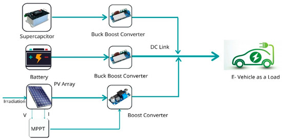
Figure 1.
Parallel connection of proposed HESS for EVs with battery–SC–PV.
3. Modeling of Hybrid Energy-Storage System Components for Electric Vehicle
Batteries and supercapacitors are prevalent energy-storage technologies within EVs. Their integration in EVs occurs in hybrid modes, serving either as primary or secondary energy sources. The modeling of hybrid energy-storage system components is mentioned in the following subsections as:
3.1. Battery
In the literature, various battery types have been devised to cater to diverse applications [30,31,32]. Typically, high-fidelity models offer exceptional accuracy in modelling but come with a significant computational burden. Such models are often better suited for advancing energy management techniques. The current study is centered on an equivalent battery model encompassing a series-connected controlled voltage source and internal resistances, as illustrated in Figure 2.
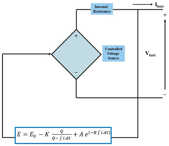
Figure 2.
The equivalent model of the battery reprinted from Ref. [33].
The battery voltage Vbat is described as
The total generated EMF is given by Equation (2) as
where E is the no-load voltage (V), E0 is the battery constant voltage (V), K is the polarization voltage (V), Q is the battery capacity (Ah), A is the exponential zone amplitude (V), and B is the inverse of exponential zone time constant in (Ah)−1. The specifications of the battery used in the proposed model are specified in Table 1.

Table 1.
Specifications of battery.
The battery discharging curve is represented in Figure 3.
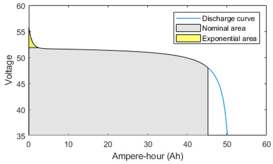
Figure 3.
Discharge curve.
3.2. Supercapacitor
In a hybrid system configuration, the primary energy source is provided by a battery, with the supercapacitor serving as a secondary energy source. Supercapacitors offer several advantages, including prolonged service life, high cycle count, rapid charging capabilities, and high power density. They are predominantly employed in applications requiring high-current discharging and rapid dynamic charging for efficient energy storage. The literature contains information on ageing, artificial intelligence, chemical, and electrical properties, as well as the dynamic structure of SC models [34,35,36,37]. The literature has also provided a basic electrical model of SCs to explain their behavior [38,39,40].
Figure 4 depicts a schematic representation of the supercapacitor’s equivalent model. Table 2 presents the detailed specifications of the supercapacitor utilized in the proposed model.
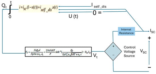
Figure 4.
Equivalent model of supercapacitor.
Table 2.
Specifications of supercapacitor.
The Stern equation is used to express the supercapacitor output voltage as
with
To represent the self-discharge phenomenon, the supercapacitor electric charge is modified as follows (when iSC = 0):
3.3. PV System
The photovoltaic system functions by converting sunlight into electrical energy. The system’s electrical current magnitude correlates directly with the incident solar radiation. Each individual PV cell typically operates within a voltage range of 0.5 to 0.8 V, generating a relatively small amount of power. PV cells are interconnected in parallel or series configurations to meet specific voltage requirements. Furthermore, PV modules are connected in parallel or series arrangements to form an array.
Illustrated in Figure 5 is the equivalent circuit model of a PV cell, which comprises a diode, shunt resistor, series resistor, and current source [41].
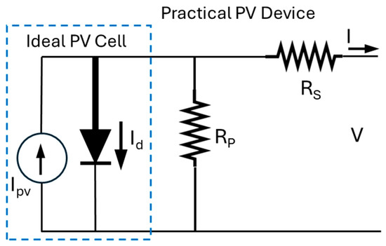
Figure 5.
Equivalent model of photovoltaic system reprinted from Ref. [41].
The output current of the PV cell is given as
where Ipv and Io are the PV and saturation currents, respectively and Vt = NskT/q is the thermal voltage of the array with Ns cells connected in series. The cells connected in parallel increase the current, and the cells connected in series provide greater output voltage. If the array consists of Np photovoltaic cells connected in parallel, then the PV current and saturation current may be expressed as
The Mitsubishi Electric PV-MLU250HC PV module is a high-efficiency solar panel designed for both residential and commercial applications. Featuring a maximum power output of 250 watts, this module utilizes advanced polycrystalline silicon cell technology to ensure superior performance and reliability. The PV-MLU250HC is engineered with an anti-reflective glass coating, enhancing light absorption, and minimizing power loss. Its robust frame and durable materials provide excellent resistance to harsh environmental conditions, including wind and snow loads. With a high module efficiency and positive power tolerance, the Mitsubishi Electric PV-MLU250HC delivers consistent energy production, making it an ideal choice for sustainable energy solutions. The specification of the module has been summarized in Table 3.
Table 3.
Specification of Mitsubishi Electric PV-MLU250HC PV module.
3.4. Boost Converter
A DC-DC boost converter stabilizes voltage by increasing the output voltage above the input voltage while using little power to compensate for the voltage deficiencies [42]. The DC-DC converter adjusts the DC output voltage and current levels while converting electrical energy without affecting power. Figure 6 shows equivalent circuit schematically how of a DC-DC converter converts voltage. Table 4 shows parameters of the boost converter.
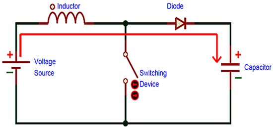
Figure 6.
Boost converter equivalent circuit diagram.
Table 4.
Specification of boost converter.
Equations (9) and (10) describe the inductor voltage and capacitor current, respectively.
Equation (11) shows the mathematical equation for the boost converter in the ON position.
Equation (12) shows the mathematical equation for the boost converter in the OFF position.
3.5. BLDC Motor
Figure 6 depicts the equivalent circuit for a BLDC motor, which may be used to define its mathematical model. Resistance (Rs) and associated inductance (Ls) indicate the stator windings for each phase. In BLDC motors, the return electromotive force (EMF) per phase (ean, ebn, and ecn) is trapezoidal rather than sinusoidal [43]. Back-EMFs are separated by 120 electrical degrees. Three hall sensors in the BLDC motor stator frame (Figure 7) allow the three-phase inverter to instantly detect the rotor magnetic field for proper switching [44]. Equations (13)–(15) provide the mathematical model equations for the BLDC motor equivalent circuit shown in Figure 7. The specifications of the BLDC motor used in this study are summarized in Table 5.
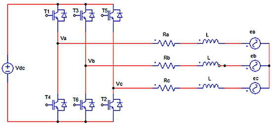
Figure 7.
Equivalent circuit diagram of BLDC motor.
Table 5.
Specification of BLDC motor.
Equation (16) represents the mechanical time constant.
The equations for the electrical time constant are represented in Equations (17) and (18) as
BLDC motors have two torque parameters: peak torque and rated torque. The continuous running of the motor allows it to reach at its rated torque. This demand occurs for a short time period, particularly when the motor starts from a standstill or accelerates. During this interval, more torque is required to overcome the inertia of the load and rotor. The motor may reach maximum torque by following the speed torque curve. The motor maintains a continuous torque zone until it reaches its maximum torque value at the specified speed. After surpassing the rated speed, the motor’s torque diminishes. Stall torque is the point on the graph when the torque is maximal but the shaft does not rotate. The no-load speed is the motor’s maximum output speed. The speed is primarily controlled by voltage and may be adjusted by adjusting the supply voltage. PWM controls the voltage, thus maintaining the speed-torque characteristics for both continuous and intermittent operation. Figure 8 illustrates the speed-torque characteristics of a BLDC motor.
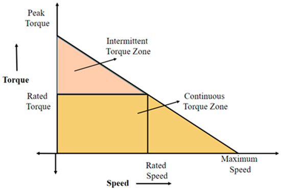
Figure 8.
Speed torque characteristics diagram.
4. Simulink Model of Proposed HESS
In this manuscript, we investigate two distinct configurations of energy-storage systems. The first configuration integrates a battery and a supercapacitor connected in parallel, while the second configuration combines a battery with a photovoltaic (PV) system, which is also connected in parallel.
4.1. Combination of Battery and Supercapacitor Connected in Parallel
The simulation of the battery and supercapacitor, which are connected in parallel, is carried out in MATLAB Simulink 2020a. Figure 9a,b represents the block schematic arrangement and MATLAB simulation diagram of the battery–supercapacitor connected in parallel for the EV system, respectively. The battery’s output voltage is directly connected to a boost converter, which elevates the voltage to a predetermined level. This amplified voltage output from the boost converter is subsequently linked to a BLDC motor. A standard trapezoidal type of BLDC motor operating at 48 V is utilized in this study.
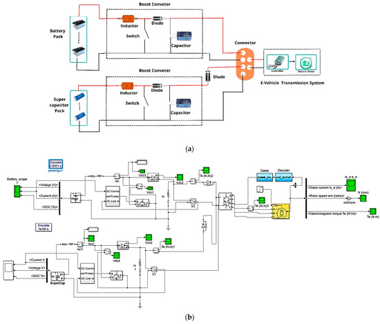
Figure 9.
(a) Block schematic arrangement and (b) Simulink diagram for battery–supercapacitor configuration connected in parallel for EV.
Additionally, the supercapacitor is connected in parallel via the boost converter. To safeguard against reverse voltage within the system, a diode is incorporated between the battery and supercapacitor’s parallel configuration.
4.2. Combination of Battery and Photovoltaic Module Connected in Parallel
Figure 10a,b illustrates the configuration of the battery and PV system connected in parallel. Figure 1 portrays the system block architecture, incorporating the solar panel with the maximum power point tracker (MPPT). In the Simulink model, the PV system’s output is directed through a controller to the DC-DC converter. The MPPT technique has been implemented in the MATLAB Simulink model to regulate the converter’s duty cycle and thus, ensuring that the battery bank is supplied while maintaining a constant DC output voltage. Under typical operational conditions where the PV output is adequate to meet the load demands, the battery bank remains floating, implying that it is fully charged.
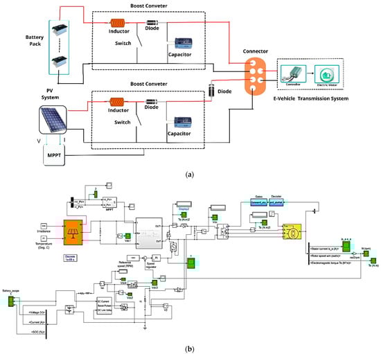
Figure 10.
(a) Block schematic arrangement for battery–PV system connected in parallel for EV and (b) Simulink model of the battery–PV system configuration connected in parallel for EV.
5. Results and Discussion
This study examines two distinct configurations of hybrid energy-storage systems for electric vehicles. The first configuration integrates a battery and a supercapacitor in parallel, while the second configuration combines a battery with a photovoltaic (PV) system in parallel. Subsequent sections elucidate the performance of these two configurations.
5.1. Combination of Supercapacitor and Battery Linked in Parallel
In this configuration, the battery and supercapacitor are connected in parallel, as illustrated in Figure 9a,b. During the starting mode, both the battery and supercapacitor are assumed to be fully charged. Initially, the voltages across the battery and supercapacitor are 40 V and 20 V, respectively, as depicted in Figure 11. As the drive system starts its operations, the motor draws current from the available voltage sources (i.e., the battery and supercapacitor), causing their voltages to increase, as shown in Figure 11. Specifically, at 0.03 s, the battery voltage reaches 52 V, and at 0.02 s, the supercapacitor voltage reaches 24 V. Subsequently, the motor speed stabilizes, indicating a constant operating condition.
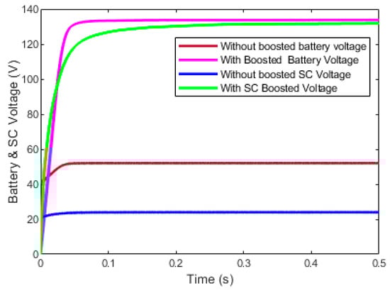
Figure 11.
Battery and supercapacitor dynamic voltage profiles with and without boost converter.
A boost converter is employed to increase the voltage level. Figure 9a,b portrays that two boost converters are connected across the energy storage devices and a motor. Figure 11 represents the battery and supercapacitor voltages with and without boost converter. In starting mode, both sources provide voltage to drive the system. In this mode, the supercapacitor voltage is greater than the battery voltage because, initially, it is assumed that the supercapacitor is in a fully charged condition. In the presence of the inductor in the boost converter, the voltages increase linearly up to 0.02 s. After 0.02 s, the capacitor is discharged so that the voltage across the supercapacitor decreases as compared to the battery voltage. The maximum flux is developed in the boost converter’s inductor to provide constant voltage to the motor. The drive system runs continuously at constant supply from 120 V to 135 V.
When the motor is connected to both supply voltages, current flows through the windings and flux is established within them. Initially, both sources are assumed to be fully charged. The supercapacitor initially delivers a very high current of 9 A as shown in Figure 12a. As the supercapacitor discharges, its voltage gradually decreases, resulting in a reduction in current, as illustrated in Figure 12a, up to 0.03 s. Simultaneously, the battery supplies voltage and thus, causing the current to rise to 3.8 A due to the motor’s characteristics or behavior as shown in Figure 12b. When the battery provides voltage, the maximum flux is established in the motor’s winding. Subsequently, the motor operates at a constant current, gradually decreasing to 0.2 A, as depicted in Figure 12b.
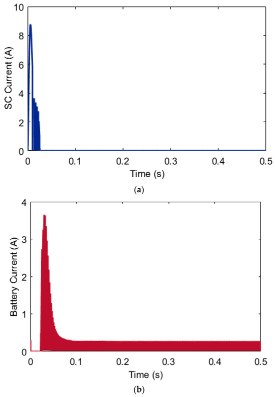
Figure 12.
(a) Supercapacitor and (b) Battery dynamic current profiles.
Figure 13 depicts the variations in power output of both the battery and supercapacitor. Initially, the supercapacitor is fully charged, delivering a higher power output of approximately 450 W. As the supercapacitor discharges, its power output gradually decreases to 280 W within 0.03 s. Concurrently, the battery supplies the voltage necessary for the motor operation, resulting in increased power consumption by the motor due to its inherent characteristics.
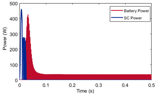
Figure 13.
Battery and supercapacitor dynamic power output profiles.
When the motor reaches maximum flux development, it operates at a constant power level. As illustrated in Figure 13, the motor power output increases to 420 W and subsequently decreases to 40 W under no-load conditions. Beyond 0.06 s, the motor maintains a steady power output to drive the system.
Figure 14 represents the BLDC motor current when the battery and supercapacitor are connected in parallel. In the BLDC motor for the generation of rotating magnetic field, hall sensors are used. In Figure 14, Phase ‘A’ is represented in yellow color, Phase ‘B’ is represented in blue color and Phase ‘C ‘ is represented in orange color. Each coil in the BLDC motor is placed at 120° of phase displacement. Initially, no flux is present in the motor winding. Therefore, motor takes a higher current at the initial stage. When all the fluxes are developed in the motor according to requirements, the motor takes a normal current, as represented in Figure 14.
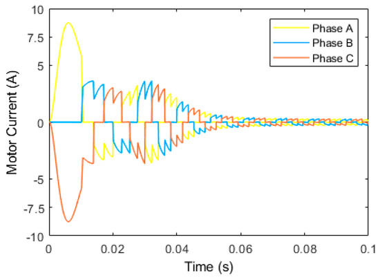
Figure 14.
BLDC motor current for the battery-supercapacitor configuration.
Figure 15 illustrates the dynamic profile of the motor speed for the battery–supercapacitor configuration. When the supply is connected, the motor’s shaft initiates acceleration, gradually increasing speed from zero. The motor speed exhibits linear growth increment until it reaches 600 rpm. During discharging mode, the supercapacitor supplies a lower voltage than the battery, causing the motor speed to rise linearly till 0.05 s. Subsequently, upon establishing maximum flux in the motor, a constant supply voltage is delivered, leading to a stabilized motor speed of 1500 rpm.
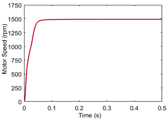
Figure 15.
Dynamic profile of motor speed for battery–supercapacitor configuration.
5.2. Combination of Battery and Photovoltaic Module Connected in Parallel
In this configuration, the battery and PV module are connected in parallel, as depicted in Figure 10. The dynamic voltage profiles of both the battery and photovoltaic (PV) system are illustrated in Figure 16. Initially, the battery voltage exhibits a linear increase from 48 V to 52 V within the first 0.03 s. Concurrently, owing to fluctuations in solar irradiance levels, the generated voltage by the PV module does not remain constant. To maintain a consistent voltage output, Maximum Power Point Tracking (MPPT) is implemented with the PV module, resulting in a stabilized voltage output of 28 V, as depicted in Figure 16. Meanwhile, the battery supplies a steady voltage to the motor for operation, and thus, enabling the establishment of maximum flux within the motor winding starting from 0.03 s. Minor deviations in PV voltage occur in response to changes in solar irradiance levels.
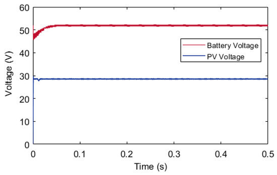
Figure 16.
Battery and PV module dynamic voltage profiles without boost converter.
Figure 17 illustrates the temporal variations of boosted voltages of the photovoltaic (PV) module and the battery. Figure 10 depicts the configuration in which two boost converters are connected across the energy storage unit and a motor. The voltages supplied by the battery and PV module alone are insufficient to power the system adequately, and thus, necessitating a voltage boost. The voltage levels are elevated to meet operational requirements using the boost converters. During the initial phase, the PV voltage surpasses that of the battery. Between 0.01 and 0.03 s, both voltages exhibit linear increments. At 0.03 s, the PV voltage exceeds the battery voltage due to the presence of an inductor in the boost converter. Subsequently, the converter stabilizes the voltage across the battery and PV terminals at 0.05 s, enabling the PV system to generate a voltage of 138 V consistently.
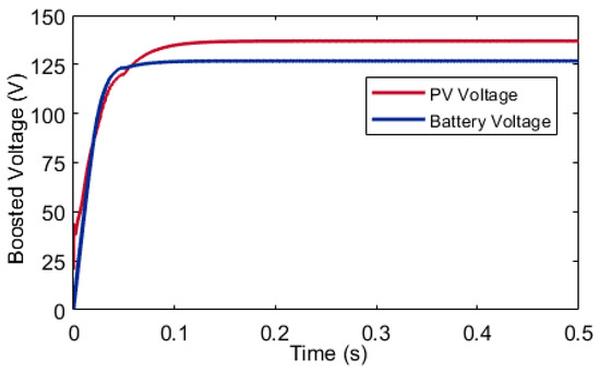
Figure 17.
Battery and PV system dynamic voltage profiles with a boost converter.
The variations in the currents drawn by the battery and PV module are depicted in Figure 18 and Figure 19, respectively. Initially, the voltage generated by the PV module exceeds that of the battery, resulting in the motor drawing a higher current from the PV module. Between 0.02 and 0.05 s, both sources exhibit linear behavior. At 0.03 s, the battery voltage surpasses the PV module’s voltage, leading to the battery supplying a higher current until 0.05 s. Subsequently, from 0.05 s onward, the PV voltage exceeds the battery voltage, and all current is sourced from the PV module. Under no-load conditions, the system module consistently provides approximately 2 A of current to the system.
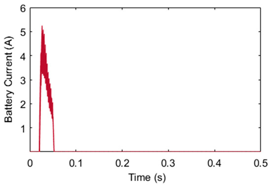
Figure 18.
Battery dynamic current profile.
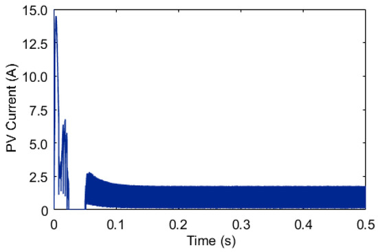
Figure 19.
PV module dynamic current profile.
Figure 20 represents the BLDC motor current when the battery and PV module are connected in parallel. Phase ‘A’, ‘B’ and ‘C’ currents are represented in blue, red and yellow colors, respectively. Each coil in the BLDC motor is placed at 120° of phase displacement. At the starting condition, there is no flux available in the winding of the motor and therefore the motor initially takes a higher current from the PV module. When all the fluxes are developed in the motor according to requirements, the motor takes a normal current, as represented in Figure 20.
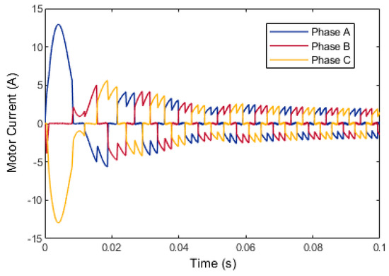
Figure 20.
BLDC motor current for the battery–PV system configuration.
The variations in battery and PV module power are depicted in Figure 21. Initially, the voltage of the PV module exceeds that of the battery, leading to the PV module supplying higher power to the motor to drive the system. Initially, the motor consumes 650 W of power, consistent with its operational characteristics, which demand higher power at the outset. As the motor windings reach maximum flux, the power consumption decreases to 550 W. Simultaneously, the battery voltage surpasses the PV voltage, prompting the motor to draw additional power, extracting 500 W from the battery, which diminishes to 150 W within 0.05 s. Subsequently, the motor consistently draws 250 W of power from the supply at a constant voltage.
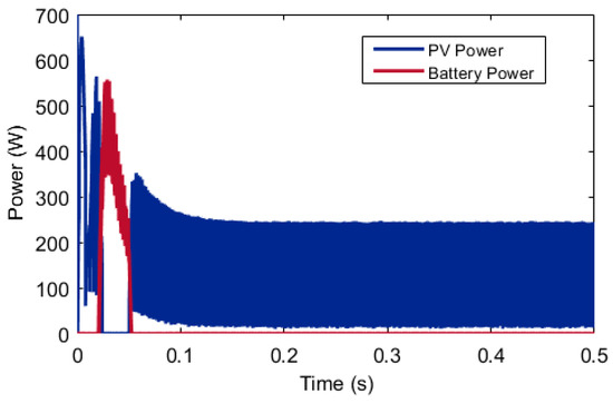
Figure 21.
Dynamic profiles of battery and PV power.
The variation of motor speed over time is depicted in Figure 22. Upon connection to the supply system, the motor’s shaft starts accelerating, initiating from zero speed. The motor’s speed increases linearly up to 700 rpm. When slight fluctuations occur in the PV voltage due to variations in the solar irradiation, resulting in a decrease in PV voltage relative to the battery, the motor’s speed resumes in linear increments until 0.05 s. Upon establishing maximum flux in the motor, a constant voltage is supplied, enabling the motor to maintain a steady speed of 1500 rpm.
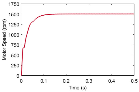
Figure 22.
Dynamic profile of motor speed for battery–PV module configuration.
A comparison of different parameters of both battery–supercapacitor and battery–PV system configurations is presented in Table 6.
Table 6.
Comparison of battery–supercapacitor and battery–PV system, both connected in parallel.
6. Conclusions
This manuscript presents the results of the simulation, which were based on two distinct configurations: (a) a battery–supercapacitor system connected in parallel and (b) a parallel combination of a battery–photovoltaic (PV) module. Both configurations were modelled using the MATLAB Simulink environment, with both energy-storage devices interconnected in parallel. A comparative analysis of various performance parameters of both configurations was conducted. Notably, it was observed that the utilization of the hybrid energy-storage system reduced the battery power consumption by up to 39%. The supercapacitor exhibits a higher current output compared to that of the battery. This characteristic enables the supercapacitor to alleviate the load on the battery during periods of high-power demand by the motor. Conversely, in the battery–PV system mode, the photovoltaic system, coupled with a boost converter, supplies higher voltage to the motor, facilitating its operation using solar energy. The promising results of this study open several avenues for future research and development. One potential direction is the optimization of the control strategies for hybrid energy-storage systems to further enhance their efficiency and reliability. Additionally, exploring the integration of more advanced supercapacitors and battery technologies could yield even greater reductions in battery power consumption and improved performance. Investigating the scalability of these configurations for larger systems or different applications, such as electric vehicles or grid storage, could provide valuable insights. Moreover, the environmental and economic impacts of widespread adoption of such hybrid systems warrant comprehensive analysis. Finally, the real-world testing and long-term performance evaluation of these systems under varying operational conditions will be crucial to validate the simulation results and to identify any practical challenges that may arise.
Author Contributions
K.R.: Methodology, Software, Investigation, and Writing—Original draft. A.S.: Reviewing, Editing and Supervision. J.C.: Reviewing, Editing and Supervision. R.L.: Conceptualization, Visualization, Investigation and Writing—Reviewing and Editing. T.M.: Reviewing, Editing and Supervision. A.R.: Visualization, Investigation, Writing—Reviewing and Editing. All authors have read and agreed to the published version of the manuscript.
Funding
This research received no external funding.
Data Availability Statement
The original contributions presented in the study are included in the article, further inquiries can be directed to the corresponding authors.
Acknowledgments
AR acknowledges University of Exeter Open Access Funding for providing open access publication to this research, facilitating the dissemination of knowledge, and contributing to the academic community. For the purpose of open access, the author has applied a Creative Commons Attribution (CC BY) license to any Author-Accepted Manuscript version arising from this submission.
Conflicts of Interest
The authors declare no conflicts of interest.
Nomenclature
| Variable | Description |
| Ai | Interfacial area between electrodes and electrolyte (m2) |
| c | Molar concentration (mol/m3) equal to c = 1/(8NAr3) |
| r | Molecular radius (m) |
| F | Faraday constant |
| isc | Supercapacitor current (A) |
| Vsc | Supercapacitor voltage (V) |
| CT | Total capacitance (F) |
| Rsc | Total resistance (ohms) |
| Ne | Number of layers of electrodes |
| NA | Avogadro constant |
| Np | Number of parallel supercapacitors |
| Ns | Number of series supercapacitors |
| QT | Electric charge (C) |
| R | Ideal gas constant |
| d | Molecular radius |
| T | Operating temperature (K) |
| ε | Permittivity of material |
| ε0 | Permittivity of free space |
| Ipv | Photovoltaic current |
| Io | Photovoltaic saturation currents |
| VT | Thermal voltage of the array |
| Ns | Cells connected in series |
| Np | Photovoltaic cells connected in parallel |
References
- Tiwari, H.; Ghosh, A.; Sain, C.; Ahmad, F.; Al-Fagih, L. Modified direct torque control algorithm for regeneration capability of IM driven electric vehicle by using hybrid energy storage system. Renew. Energy Focus J. 2024, 48, 100534. [Google Scholar] [CrossRef]
- Kumar, A.; Sadasivuni, K.K. Comparison of BPN, RBFN and Wavelet Neural Network in Induction Motor Modelling for Speed Estimation. Int. J. Ambient. Energy 2020, 43, 3246–3251. [Google Scholar] [CrossRef]
- Kumar, A.; Suresh, R.M.; Sharmila, B.; Panchal, H.; Gokul, C.; Udhayanatchi, K.V.; Sadasivuni, K.K.; Israr, M. A Novel Method for Arduino Based Electric Vehicle Emulator. Int. J. Ambient. Energy 2021, 30, 4299–4304. [Google Scholar] [CrossRef]
- Ehasani, M.; Gao, Y.; Emadi, A. Modern Electric, Hybrid Electric, Fuel Cell Vehicle: Fundamentals, Theory, and Design; CRC Press: Portland, OR, USA, 2005. [Google Scholar]
- Wang, Y.; Yuan, H.; Martinez, A.; Hong, P.; Xu, H.; Bockmiller, F.R. Polymer electrolyte membrane fuel cell and hydrogen station networks for automobiles: Status, technology, and perspectives. Adv. Appl. Energy 2021, 2, 100011. [Google Scholar] [CrossRef]
- Xu, J.; Zhang, C.; Wan, Z.; Chen, X.; Chan, S.H.; Tu, Z. Progress and perspectives of integrated thermal management systems in PEM fuel cell vehicles: A review. Renew. Sustain. Energy Rev. 2022, 155, 111908. [Google Scholar] [CrossRef]
- Fathima, A.H.; Palanisamy, K. Integration and energy management of a hybrid Li-VRB battery for renewable applications. Renew. Energy Focus J. 2019, 30, 13–20. [Google Scholar] [CrossRef]
- Shah, A.; Shah, K.; Shah, C.; Shah, M. State of charge, remaining useful life and knee point estimation based on artificial intelligence and Machine learning in lithium-ion EV batteries: A comprehensive review. Renew. Energy Focus J. 2022, 42, 146–164. [Google Scholar] [CrossRef]
- Arun, V.; Kannan, R.; Ramesh, S.; Vijayakumar, M.; Raghavendran, P.S.; Ramkumar, M.S.; Anbarasu, P.; Sundramurthy, V.P. Review on Li-Ion Battery vs Nickel Metal Hydride Battery in EV. Adv. Mater. Sci. Eng. 2022, 2, 7910072. [Google Scholar] [CrossRef]
- Han, H.; Xu, H.; Yuan, Z.; Zhao, Y. Modeling for lithium-ion battery used in electric vehicles. In Proceedings of the 2014 IEEE Conference and Expo Transportation Electrification Asia-Pacific (ITEC Asia-Pacific), Beijing, China, 31 August–3 September 2014; pp. 1–5. [Google Scholar] [CrossRef]
- Burke, A.; Liu, Z.; Zhao, H. Present and future applications of supercapacitors in electric and hybrid vehicles. In Proceedings of the 2014 IEEE International Electric Vehicle Conference (IEVC), Florence, Italy, 17–19 December 2014; pp. 1–8. [Google Scholar] [CrossRef]
- Kouchachvili, L.; Yaïci, W.; Entchev, E. Hybrid battery/supercapacitor energy storage system for the electric vehicles. J. Power Sources 2018, 374, 237–248. [Google Scholar] [CrossRef]
- Sadeq, T.; Wai, C.K.; Morris, E.; Tarboosh, Q.A.; Aydogdu, O. Optimal Control Strategy to Maximize the Performance of Hybrid Energy Storage System for Electric Vehicle Considering Topography Information. IEEE Access 2020, 8, 216994–217007. [Google Scholar] [CrossRef]
- SMaitreya, S.; Dangi, H.S.; Naruka, N.S.; Paliwal, P. Analysis of Solar Powered Electric Vehicles. In Proceedings of the IEEE 2nd International Conference on Electrical Power and Energy Systems (ICEPES), Bhopal, India, 10–11 December 2021; pp. 1–4. [Google Scholar] [CrossRef]
- Alwesabi, Y.; Mohammed, N. Self-sufficient solar power and electric vehicle penetration: A case study of New York State. Renew. Energy Focus 2023, 45, 133–140. [Google Scholar] [CrossRef]
- Nivas, M.; Naidu, R.K.P.R.; Mishra, D.P.; Salkuti, S.R. Modeling and analysis of solar-powered electric vehicles. Int. J. Power Electron. Drive Syst. 2022, 13, 480–487. [Google Scholar] [CrossRef]
- Robinson, S.A.; Rai, V. Determinants of spatio-temporal patterns of energy technology adoption: An agent-based modeling approach. Appl. Energy 2015, 151, 273–284. [Google Scholar] [CrossRef]
- Fakour, H.; Imani, M.; Lo, S.-L.; Yuan, M.-H.; Chen, C.-K.; Mobasser, S.; Muangthai, I. Evaluation of solar photovoltaic carport canopy with electric vehicle charging potential. Sci. Rep. 2023, 13, 2136. [Google Scholar] [CrossRef]
- Hossain, M.S.; Kumar, L.; Assad, M.E.H.; Alayi, R. Advancements and Future Prospects of Electric Vehicle Technologies: A Comprehensive Review. Complexity 2022, 2022, 21. [Google Scholar] [CrossRef]
- Diahovchenko, I.; Petrichenko, L.; Borzenkov, I.; Kolcun, M. Application of photovoltaic panels in electric vehicles to enhance the range. Heliyon 2022, 8, e12425. [Google Scholar] [CrossRef] [PubMed]
- Pelay, U.; Luo, L.; Fan, Y.; Stitou, D.; Rood, M. Thermal energy storage systems for concentrated solar power plants. Renew. Sustain. Energy 2017, 79, 82–100. [Google Scholar] [CrossRef]
- Tossa, A.K.; Soro, Y.M.; Thiaw, L.; Azoumah, Y.; Sicot, L.; Yamegueu, D.; Lishou, C.; Coulibaly, Y.; Razongles, G. Energy performance of different silicon photovoltaic technologies under hot and harsh climate. Energy 2016, 103, 261–270. [Google Scholar] [CrossRef]
- Moro, A.; Boelman, E.; Joanny, G.; Lopez-Garcia, J. A bibliometric-based technique to identify emerging photovoltaic technologies in a comparative assessment with expert review. Renew. Energy J. 2018, 123, 407–416. [Google Scholar] [CrossRef]
- Mohammad, A.; Zuhaib, M.; Ashraf, I.; Alsultan, M.; Ahmad, S.; Sarwar, A.; Abdollahian, M. Integration of Electric Vehicles and Energy Storage System in Home Energy Management System with Home to Grid Capability. Energies 2021, 14, 8557. [Google Scholar] [CrossRef]
- Umair, M.; Hidayat, N.M.; Ahmad, A.S.; Ali, N.H.N.; Mawardi, M.I.M.; Abdullah, E. A renewable approach to electric vehicle charging through solar energy storage. PLoS ONE 2024, 19, e0297376. [Google Scholar] [CrossRef]
- Nguyen, T.-T.; Kim, H.W.; Lee, G.H.; Choi, W. Design and implementation of the low cost and fast solar charger with the rooftop PV array of the vehicle. Sol. Energy 2013, 96, 83–95. [Google Scholar] [CrossRef]
- Sasikumar, G.; Sivasangari, A. Design and Development of Solar Charging System for Electric Vehicles: An Initiative to Achieve Green Campus. Nat. Environ. Pollut. Technol. Int. Q. Sci. J. 2021, 20, 801–804. [Google Scholar] [CrossRef]
- Almasri, R.A.; Alharbi, T.; Alshitawi, M.S.; Alrumayh, O.; Ajib, S. Related Work and Motivation for Electric Vehicle Solar/Wind Charging Stations: A Review. World Electr. Veh. J. 2024, 15, 215. [Google Scholar] [CrossRef]
- Hafeez, F.; Mas’ud, A.A.; Al-Shammari, S.; Sheikh, U.U.; Alanazi, M.A.; Hamid, M.; Azhar, A. Autonomous Vehicles Perception, Acceptance, and Future Prospects in the GCC: An Analysis Using the UTAUT-Based Model. World Electr. Veh. J. 2024, 15, 186. [Google Scholar] [CrossRef]
- Li, J.; Mazzola, M.S. Accurate battery pack modeling for automotive applications. J. Power Sources 2013, 237, 215–228. [Google Scholar] [CrossRef]
- Zubi, G.; Adhikari, R.S.; Sánchez, N.E.; Acuña-Bravo, W. Lithium-ion battery-packs for solar home systems: Layout, cost and implementation perspectives. J. Energy Storage 2020, 32, 101985. [Google Scholar] [CrossRef]
- Li, J.; Mazzola, M.S.; Gafford, J.; Jia, B.; Xin, M. Bandwidth based electrical-analogue battery modeling for battery modules. J. Power Sources 2012, 218, 331–340. [Google Scholar] [CrossRef]
- Narasimhulu, N.; Krishnam Naidu, R.S.R.; Falkowski-Gilski, P.; Divakarachari, P.B.; Roy, U. Energy Management for PV Powered Hybrid Storage System in Electric Vehicles Using Artificial Neural Network and Aquila Optimizer Algorithm. Energies 2022, 15, 8540. [Google Scholar] [CrossRef]
- Islam, M.S.; Hossain, M.B.; Hossain, M.N.; Alam, S.B.; Enamul, M.; Chowdhury, H. Modeling of a double-layer capacitor with individual branch response. In Proceedings of the World Congress on Engineering and Computer Science, San Francisco, CA, USA, 20–22 October 2010; Volume 2. [Google Scholar]
- Zhang, L.; Hu, X.; Wang, Z.; Sun, F.; Dorrell, D.G. A review of supercapacitor modelling, estimation, and applications: A control/management perspective. Renew. Sustain. Energy Rev. 2018, 81, 1868–1878. [Google Scholar]
- Zou, C.; Zhang, L.; Hu, X.; Wang, Z.; Wik, T.; Pecht, M. A review of fractional-order techniques applied to lithium-ion batteries, lead-acid batteries, and supercapacitors. J. Power Sources 2018, 390, 286–296. [Google Scholar] [CrossRef]
- Ferahtia, S.; Djerioui, A.; Zeghlache, S.; Houari, A. A hybrid power system based on fuel cell, photovoltaic source and super capacitor. SN Appl. Sci. 2020, 2, 940. [Google Scholar] [CrossRef]
- Kachhwaha, A.; Rashed, G.I.; Garg, A.R.; Mahela, O.P.; Khan, B.; Shafik, M.B.; Hussien, M.G. Design and Performance Analysis of Hybrid Battery and Ultracapacitor Energy Storage System for Electrical Vehicle Active Power Management. Sustainability 2022, 14, 776. [Google Scholar] [CrossRef]
- Lahyani, A.; Venet, P.; Guermazi, A.; Troudi, A. Battery/supercapacitors combination in uninterruptible power supply (UPS). IEEE Trans. Power Electron. 2013, 28, 1509–1522. [Google Scholar] [CrossRef]
- Rafik, F.; Gualous, H.; Gallay, R.; Crausaz, A.; Berthon, A. Frequency, thermal and voltage supercapacitor characterisation and modelling. J. Power Sources 2007, 165, 928–934. [Google Scholar] [CrossRef]
- Ajiatmo, D.; Robandi, I. Modeling and simulation performance of photovoltaic system integration battery and supercapacitor paralellization of MPPT prototype for solar vehicle. AIP Conf. Proc. 2017, 1818, 020076. [Google Scholar] [CrossRef]
- Chen, S.Y.; Yang, B.C.; Pu, T.A.; Chang, C.H.; Lin, R.C. Active current sharing of a parallel DC-DC converters system using bat algorithm optimized two-DOF PID control. IEEE Access 2019, 7, 84757–84769. [Google Scholar] [CrossRef]
- Ridwan, M.; Yuniarto, M.N.; Soedibyo. Electrical Equivalent Circuit Based Modeling and Analysis of Brushless Direct Current (BLDC) Motor. In Proceedings of the 2016 International Seminar on Intelligent Technology and Its Application (ISITIA 2016): Recent Trends in Intelligent Computational Technologies for Sustainable Energy, Lombok, Indonesia, 28–30 July 2016; pp. 471–478. [Google Scholar] [CrossRef]
- Archana, M.; Thulasi, J.A.; Ananth, M.B. An efficient solar power based four quadrant operation of BLDC motor. In Proceedings of the International Conference on Electrical, Electronics, and Optimization Techniques (ICEEOT 2016), Chennai, India, 3–5 March 2016; pp. 4841–4846. [Google Scholar] [CrossRef]


Disclaimer/Publisher’s Note: The statements, opinions and data contained in all publications are solely those of the individual author(s) and contributor(s) and not of MDPI and/or the editor(s). MDPI and/or the editor(s) disclaim responsibility for any injury to people or property resulting from any ideas, methods, instructions or products referred to in the content. |
© 2024 by the authors. Licensee MDPI, Basel, Switzerland. This article is an open access article distributed under the terms and conditions of the Creative Commons Attribution (CC BY) license (https://creativecommons.org/licenses/by/4.0/).