Article

Detecting Wheel Slip to Suppress Self-Excited Oscillations in Braking Mode

by
Aleksander V. Klimov
1,2,
Baurzhan K. Ospanbekov
1,2,
Akop V. Antonyan
1,2,
Viktor R. Anisimov
1,2,
Egor A. Dvoeglazov
1,2,
Danila A. Novogorodov
1,
Andrey V. Keller
1,3,
Sergey S. Shadrin
1,3,
Daria A. Makarova
1,3,
Vladimir S. Ershov
1,* and
Yury M. Furletov
1
1
Ground Transportation and Technological Complexes Department, Moscow Polytechnic University, Moscow 107023, Russia
2
KAMAZ Innovation Center LLC, Moscow 121205, Russia
3
Sociocenter, Moscow 123104, Russia
*
Author to whom correspondence should be addressed.
World Electr. Veh. J. 2024, 15(8), 340; https://doi.org/10.3390/wevj15080340
Submission received: 18 June 2024 / Revised: 21 July 2024 / Accepted: 24 July 2024 / Published: 28 July 2024

Abstract

:
The wheels of decelerating vehicles in braking mode roll with increased slip, up to complete lock-up, which is a negative phenomenon. This is effectively managed by the anti-lock braking system (ABS). However, in the course of braking, especially before the system activation, self-excited oscillatory processes with high amplitudes may occur, causing increased dynamic loads on the drive system. The paper studies the braking processes of a vehicle with an electromechanical individual traction drive in both electrodynamic regenerative and combined braking modes, utilizing the drive and the primary braking system. The theoretical framework is provided for identifying the self-excited oscillation onset conditions and developing a technique to detect wheel slips during braking to suppress these oscillations. To check the functionality of the wheel-slip observer in braking mode, the performance of the self-excited oscillation pulse suppression algorithm was studied in the MATLAB Simulink 2018b software package. The study results can be used to develop control systems equipped with the function of suppressing self-excited oscillations by vehicle motion.

1. Introduction

The reliability and efficiency of transport work are directly influenced by the nature of the processes occurring in the contact area between the wheel and the road. In the case of the contact interaction of two bodies, in a number of cases, oscillatory processes arise, which are vibrations of parts of the bodies relative to each other [1,2].
The contact interaction of an elastic tire with the road is characterized by friction. The nature of friction in the contact zone has a direct impact on both the safety of wheeled vehicles [3,4,5,6] and their efficiency.
For road transport, the problem of the occurrence of self-oscillations of steered wheels has long been known, which was successfully solved by the optimal spatial position of the wheel-turning axes in order to create stabilizing torques [7].
Works [8,9] consider the occurrence of self-oscillations during the braking of a car when the wheels are blocked in the event of their sliding when the friction force decreases. Analytical expressions are given that show what parameters need to be changed to reduce the amplitude of self-oscillations. These works do not consider the driving mode during the operation of the anti-lock braking system in free and driven wheel-rolling modes. Other driving conditions under which increased slip may occur when the friction force decreases were not considered.
Works [10,11,12,13,14,15,16,17,18,19] study the processes occurring in the contact zone of the elastic wheel with the support base in the braking mode, including during the operation of the anti-lock braking system and the free rolling of the wheel, the appearance of oscillatory phenomena and their impact on motion stability, the appearance of vibrations, and noise effects; however, the process of excitation of self-oscillations is not considered.
In [20], the conditions for the occurrence of self-oscillatory processes in the interaction zone of an elastic tire with a solid support base are considered under three wheel-rolling modes: traction, driven, and braking. It is indicated that the occurrence of self-oscillations can be a diagnostic sign of loss of wheel traction, allowing active safety systems to react to the loss of traction in advance. However, the work does not consider the effect on the drive, does not take into account the features of the electric drive itself, and does not provide methods for suppressing self-oscillating phenomena when they arise. Also, the issues of the occurrence of oscillatory phenomena during the joint operation of braking and drive systems are not considered.
In general, the issues of excitation of self-oscillations for various wheel-rolling modes, taking into account the properties of the electromechanical drive, including the complex operation of the traction drive and braking system for wheeled vehicles, have been poorly studied.
In automobile transmissions, there is a significant number of rubbing elements, as well as direct friction units; drive elements also have elastic connections and gaps in the gears, which can lead to an increase in dynamic load due to the excitation of oscillatory phenomena [21,22,23,24,25,26,27].
Work [28] discusses methods for the dynamic loading of power transmissions with friction elements based on improving model properties using the choice of the characteristics of an elastic-friction torsional vibration damper. However, the conditions and the fact of the occurrence of self-oscillating phenomena in transmissions due to the nonlinear properties of the friction characteristics in the elements, the gaps in engagement, and the elasticity of the connections are not considered. In work [29], the parameters of the elements and components of a car transmission on the level of frictional self-oscillations were studied. Recommendations were given to reduce the tendency of the transmission to frictional self-oscillations, and the process of the generation of self-oscillations when starting off was studied. In [30], the conditions for the occurrence of self-oscillations when shifting gears in mechanical transmissions with an increased number of gears with close gear ratios were studied. In [10], a method for reducing the self-oscillations of brake mechanisms when compressed air is supplied to the friction pair zone is considered.
The use of battery-powered wheeled vehicles in transport operations is increasing. Of these, we can distinguish large-class electric buses that transport passengers. These vehicles are equipped with a rechargeable electrical energy storage system (traction battery) and a traction electric drive of the drive wheels.
For these machines, there is an urgent question of maximizing their energy efficiency since consumers are constantly and rigorously tightening their requirements for this area, which is expressed in increasing the power reserve per charge of the rechargeable electrical energy storage system. Operating organizations and consumers are increasingly tightening their requirements for range. Therefore, the primary task of developers is to reduce energy losses in power plants, drives, and other auxiliary systems. Significant losses are observed in the traction electric drive of the drive wheels.
Therefore, developers need to constantly solve the problem of increasing the power reserve, both through the use of components and systems with less energy loss, and the use of control algorithms that allow them to be used most efficiently.
Self-oscillatory phenomena in the zone of interaction between the wheel and the ground, with increased or full sliding for a tractor road train, lead to galloping and yaw due to vertical and longitudinal oscillatory movements of the wheel centers [11]. The conditions for the occurrence of oscillatory processes in the contact zone of a pneumatic tire with the ground depend on the normal load on the tire, the rate of its change, and its rigidity [12].
Of particular interest is the preventive recognition of the process of self-oscillation generation at an early stage in order to eliminate the loss of motion stability and prevent an increase in the dynamic load of the drive, or at least minimize its consequences, especially in the case of active safety systems [13,14,15,16,31,32,33].
Basically, when braking, the occurrence of oscillatory phenomena in the systems of a transport vehicle is considered either as a side effect or as a diagnostic sign of increased slip, which provokes wheel locking. However, a classic ABS allows initial blocking of the wheel, that is, it works after the occurrence of a dangerous phenomenon, fighting its consequences. If the wheel locks, a skid may occur—especially when performing braking combined with a maneuver. The use of this feature allows you to improve the operation of the ABS by eliminating the blocking phenomenon and preventing it.
To do this, it is necessary to investigate the possibility of the generation of self-oscillations, their causes, conditions, and places of occurrence. This can be completed by analyzing a system of differential equations that describe the process of braking and confirming the conclusions by experimental studies of braking.
The purpose of the research is to develop a control algorithm that allows for suppressing self-oscillating phenomena, as well as testing its performance and efficiency using simulation methods and experimental research.

2. Materials and Methods

2.1. Slip Detection Necessity to Suppress Self-Oscillations

In modern eco-friendly vehicles such as high-capacity electric buses [31], the individual drive of the driving wheels is widely used and promising (Figure 1a), which allows for a low flat floor and maximum passenger capacity. For this drive scheme, studying and monitoring the nature of the tire-support base interaction is especially important since it affects driving safety in both traction and braking modes. In the rolling-tire—road-contact area, both partial and complete (lock-up) slips may occur. This is particularly evident when driving on surfaces with low adhesion properties (e.g., ice). Increased or complete wheel slip degrades adhesion properties and may cause partial or complete loss of control and mobility [32,33,34,35]. Studying the processes occurring in the elastic-tire–solid-support-base interaction zone is of particular interest since they directly affect the safety of wheeled vehicles. Figure 1b shows the design scheme of the system with three degrees of freedom for the elastic-tire–solid-support-base interaction, described by the system of differential Equation (1) [36,37,38,39].
In the analytical analysis for the excitation of self-oscillatory phenomena, the Bendixson criterion Q = f 1 x 1 + f 1 v 1 0 and a diagnostic indicator L = 1 16 3 f y 3 + 1 16 ω 2 f y 2 were used for analysis [39]. During the electrified vehicle braking, an electrodynamic braking mode with the involvement of the drive and primary brake system, and a combined braking mode with the involvement of 2 systems may occur.
x ˙ 1 = v 1 ; v ˙ 1 = c M x 1 + x 2 ; x ˙ 2 = v 2 ; v ˙ 2 = 1 m F + c x 1 c x 2 ; ϕ ˙ K = ω K ; ω ˙ K = 1 J K c m ϕ m ϕ K + F r K M K ; ϕ ˙ m = ω m ; ω ˙ m = 1 J m c m ϕ m ϕ K M t .
Based on the analysis of the behavior of the Bendixson criterion Q, self-oscillations are characteristic of the translational movement of the machine’s supporting system (Q = 0), which is expressed by jerks and jolts, as well as for the rotational movement of the rotor shaft of the drive motor (Q = 0), which can manifest itself in fluctuations in the current consumed by the drive.
The Q function is sign-constant for the partial wheel slip in the regenerative or other braking modes. Self-excited oscillations in the interaction zone are impossible in this case. In the case of combined braking, the Q function is sign-changing, and the diagnostic criterion L < 0. We have a “soft” self-excited oscillation mode. This transmission loading mode is dangerous since the oscillation amplitudes increase sharply during intense braking [40], which may lead to vehicle jerking in the longitudinal direction and damage to transmission elements. Thus, during intense braking at high initial speeds, the total braking torque should be reduced to avoid damage, e.g., by decreasing the regenerative torque of the traction motor.
For complete wheel slip, the system of differential equations takes the following form (2):
x ˙ 1 = v 1 ; v ˙ 1 = c M x 1 + x 2 ; x ˙ 2 = v 2 ; v ˙ 2 = 1 m F + c x 1 c x 2 .
In this case, the Q function is sign-changing, and the diagnostic criterion L > 0. Thus, we have a “hard” self-excited oscillations mode. Such conditions arise during braking when the slip speed of the locked wheels falls into the region characterized by a decrease in friction force with decreasing slip speed.
Further research into the occurrence of self-oscillations must be carried out using experimental research methods of vehicle motion, which will confirm the above conclusions.

2.2. Studying Self-Excited Oscillation in Individual Drives of Large-Capacity Electric Buses during Braking

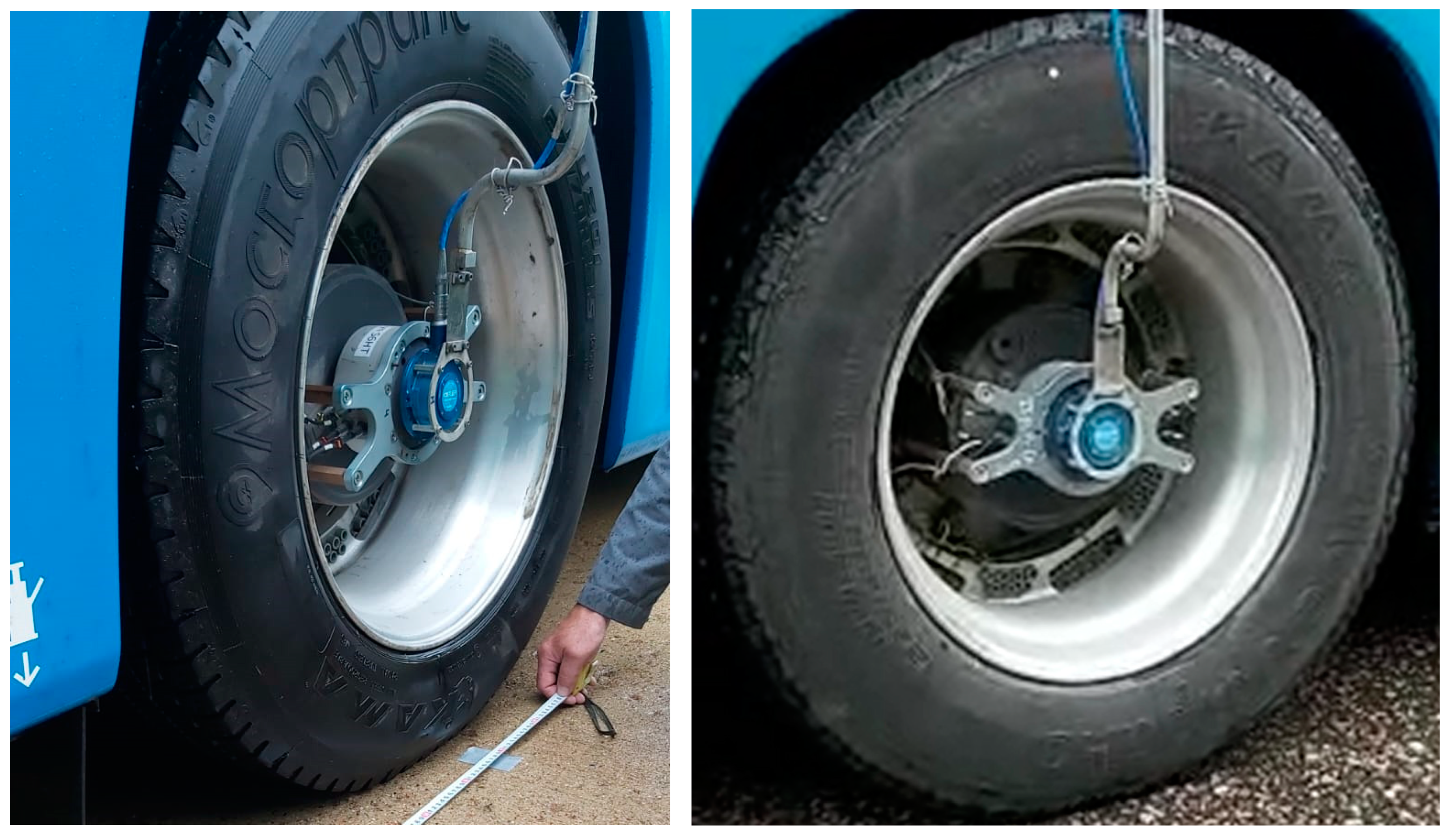
It is necessary to study the modes of movement of vehicles with increased slip for the possibility of excitation of self-oscillatory effects. The acceleration of an electric bus equipped with Kistler-Rim (Figure 2) strain gauge wheels [41] on a flat asphalt surface up to 20 km/h has been experimentally studied, followed by braking with maximum deceleration, the brake pedal fully pressed, and the wheel lock-up occurring until the anti-lock braking system (ABS) has been activated.
To capture data, a Vector VN1630A adapter was used to connect the CAN network to the computer. Vector CANoe 8.0 software was used for data analysis. The working window of the Vector CANoe program is shown in Figure 3a and the MATLAB Simulink is shown in Figure 3b.
In addition to recording data from the CAN bus, the values of torque and angular velocities on the drive wheels were recorded using Kistler RoaDyn (Kistler Holding AG, Winterthur, Switzerland) strain gauge wheels. Measuring wheels installed on the hub of the drive wheels are shown in Figure 4. Using recording equipment IMC-CRFX-400 (imc Test & Measurement GmbH, Berlin, Germany), the values of the torque and the speed of the rotation of the drive wheels were recorded.
Additionally, the values of direct current consumed by the traction electromechanical drives are measured to determine the nature of the impact of excited oscillatory phenomena.
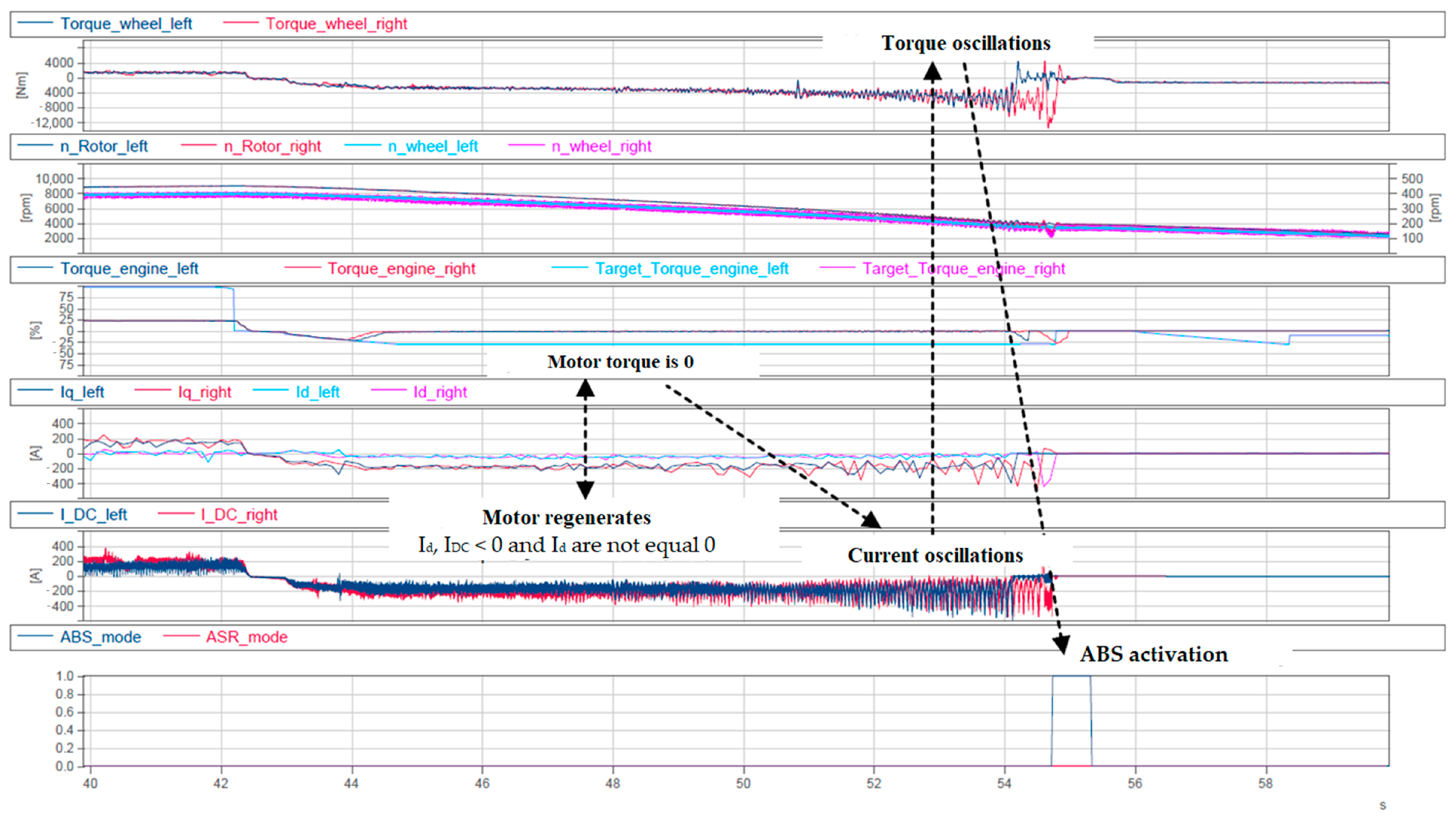
During these tests, self-excited oscillations in the interaction zone were observed and recorded until the ABS activation, confirming analytical findings. Figure 4 shows that during braking, self-excited oscillations of the torque, wheel-rotation frequency, and currents in the motor windings Iq, Id, and the DC link IDC occur. There is a noticeable increase in the amplitude of oscillations of the torque and rotation frequency just before the ABS activation. This braking process was accompanied by increased oscillations of the vehicle support base, which causes increased dynamic loads on both the drive’s mechanical part and the elements of the supporting and cushion systems, and negatively affects the driver and passengers.
Increased wheel slip in various braking modes adversely affects road-holding ability, controllability, and the operation of electrical equipment due to current oscillations, which reduce its life. As high oscillation intensities exceed permissible limits, the control system shuts down electrical equipment components such as the traction inverter and the traction battery. This situation occurred during test drives. In this case, the vehicle becomes completely uncontrollable, potentially posing the threat of an accident. To eliminate or reduce these negative impacts, it is necessary to monitor wheel slip and regulate the regenerative torque applied to the driving wheel, coordinating it with the required torque based on the tire–road adhesion properties.
Thus, it has been experimentally established that with increased sliding, when in the contact patch of the wheel with the road, with increasing sliding speed, the friction force decreases and excitation of self-oscillations is observed.

2.3. Wheel Slip Observer Operation Algorithm in a Control System with Self-Excited Oscillation Suppression Function

A major challenge in wheel-slip regulation is the assessment of the linear speed vector of the wheel center V1 and V2 (Figure 5). The linear speed of any point of the vehicle should be pre-determined. To do this, a two-component linear acceleration sensor is used to measure jx and jy. This sensor is typically placed as close to the center of gravity (C point) as possible.
The projections of the vehicle’s linear speed vector V C X and V C Y can be determined as follows:
V C X = V C X 0 + 0 t j x d t + 0 t ω z V C X d t ; V C Y = V C Y 0 + 0 t j y d t 0 t ω z V C Y d t ,
where VCX0 and VCY0 are the projections of VCX and VCY at the brake pedal pressing moment; t is the braking duration (t = 0 is the brake pedal pressing moment).
Since braking is a relatively short-duration process (a few dozen seconds maximum), the accumulated integration error will not significantly affect the control system’s performance.
The VCX0 and VCY0 projections of the VC speed vector of the center of mass on the X and Y axes of the moving coordinate system at the brake pedal pressing moment can be expressed as follows:
V C X 0 = V 10 cos Θ 1 ; V C Y 0 = V 10 sin Θ 1 ω z l 1 ; Θ 1 = Θ 1 l e f t + Θ 1 r i g h t 2 ,
where Θ1left and Θ1right are the steering angles of the left and right front wheels at the brake pedal pressing moment.
V10 is the velocity vector V1 of the front axle center at the brake pedal pressing moment V 10 ω 1 l e f t 0 + ω 1 r i g h t 0 2 . ω1left0 and ω1right0 are the angular rotation speeds of the front axle right and left wheels at the brake pedal pressing moment. r s t is the static wheel radius.
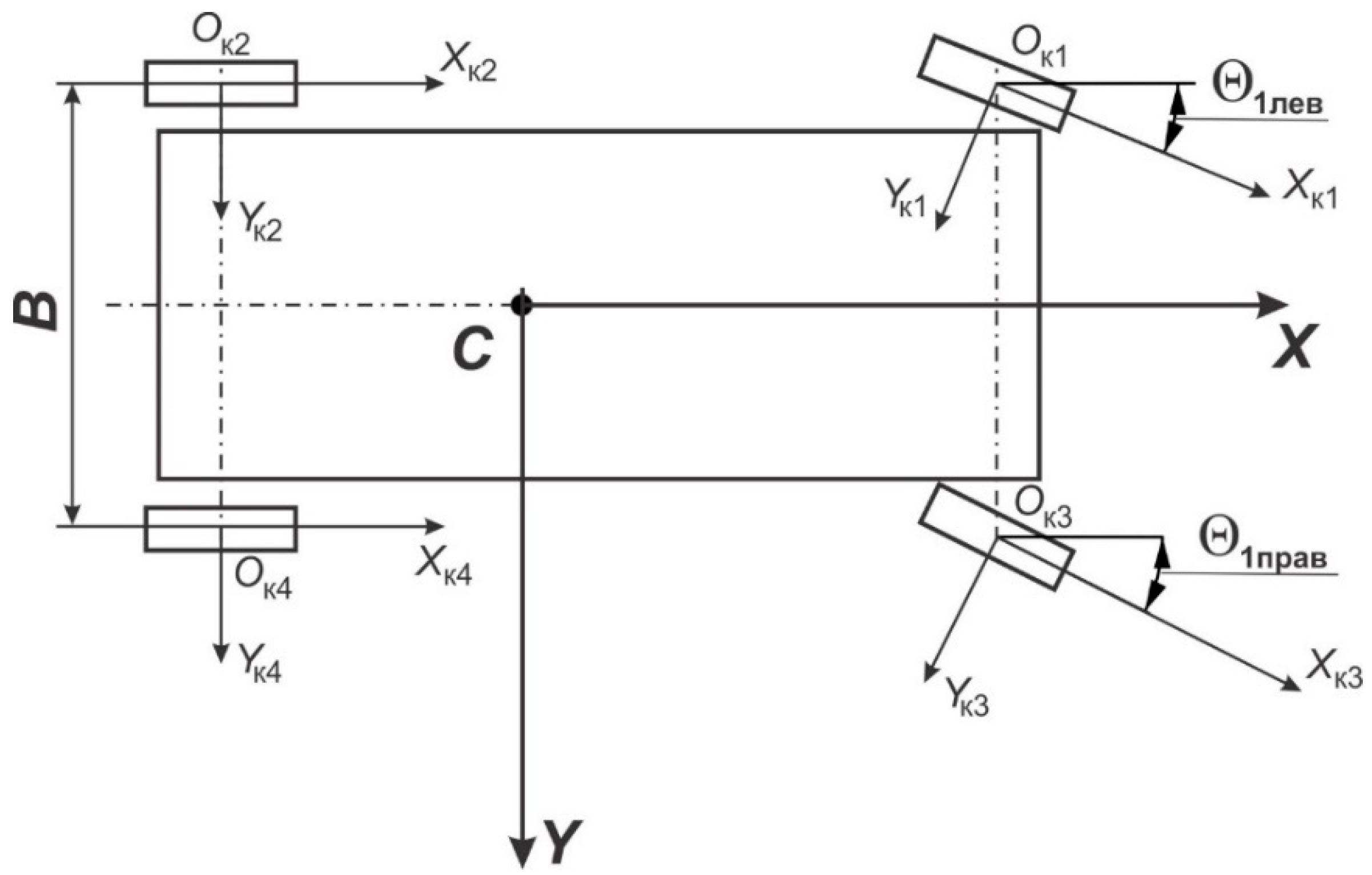
To determine the current linear speed of the wheel centers during braking, consider the design scheme in Figure 6. For the front axle wheels, the projections VKX1,3 and VKY1,3 of the linear speed of the wheel centers on the CXY mobile coordinate system axes are determined as follows:
V K X 1 = V C X ω z C O K 1 sin α 1 ; V K X 3 = V C X + ω z C O K 1 sin α 1 ; V K Y 1,3 = V C Y + ω z C O K 1,3 cos α 1 ; C O K 1 = l 1 2 + B 2 4 ; α 1 = a r c t g B 2 l 1 .
The projections VXKi, (i = 1, 3) of the speed of the front wheel centers on the axes of the OKiXKiYKi (i = 1, 3) coordinate systems associated with the front wheel centers are calculated as follows:
V X K 1 = V K X 1 cos Θ 1 л e B + V K Y 1 sin Θ 1 л e B ; V X K 3 = V K X 3 cos Θ 1 л e B + V K Y 3 sin Θ 1 л e B .
For the unsteered 2nd and 4th wheels of the rear axle:
V X K 2 = V C X ω z C O K 2 sin α 2 ; V X K 4 = V C X ω z C O K 4 sin α 2 ; α 2 = a r c t g B 2 l 2 .
The Si slip of the i-th wheel is determined as follows:
d w i = V X K i ω i r C T V X K i ,
where ωi is the measured angular speed of the i-th wheel’s rotation (i = 1, 3).
As noted above, during braking, self-excited oscillations may occur for both the translational motion of elements associated with the body 1 and the rotational motion of elements associated with the rotor shaft 7 (Figure 1b). For vehicles with individual traction drives, increased slip and blocking during full slip can be eliminated, and self-excited oscillations suppressed by controlling the motors during regenerative and combined braking. Studies [41,42] consider self-excited oscillations as those with negative damping, associated with the main motion and losing stability, and can be eliminated by excluding the motion causing them from the system. Upon detecting increased wheel slip, the control system should assess the regenerative torque on the motor shaft and the resistance torque on the wheel, and calculate the value of additional damping torques to eliminate negative damping in the wheel–road system.
x ˙ 1 = v 1 ; v ˙ 1 = c M x 1 + x 2 ; ϕ ˙ m = ω m ; ω ˙ m = 1 J m c m ϕ m ϕ K M t + K w ω K f r e l a y .
During the vehicle’s normal braking, when the driving wheel slip d w i does not exceed d w i 0.3 , i = 2 ; 4 , K w = 0 .
At a threat of wheel locking d w i > 0.3 , the damping factor K w is determined by the formula:
K w 2 J K c m
The angular stiffness c m i for the i-th wheel can be estimated during control as follows:
c m i = Δ M t i Δ ω K i ; i = 1,2 ;
where the increments of electromagnetic torque Δ M t 2 = M t 2 ( t j ) M t 2 ( t j 1 ) , Δ M t 4 = M t 4 ( t j ) M t 4 ( t j 1 ) , the increments of angular speed of the wheels are Δ ω k 2 = ω k 2 ( t j ) ω k 2 ( t j 1 ) , Δ ω k 4 = ω k 4 ( t j ) ω k 4 ( t j 1 ) ; and t j   and   t j 1 are the current and previous time instants.
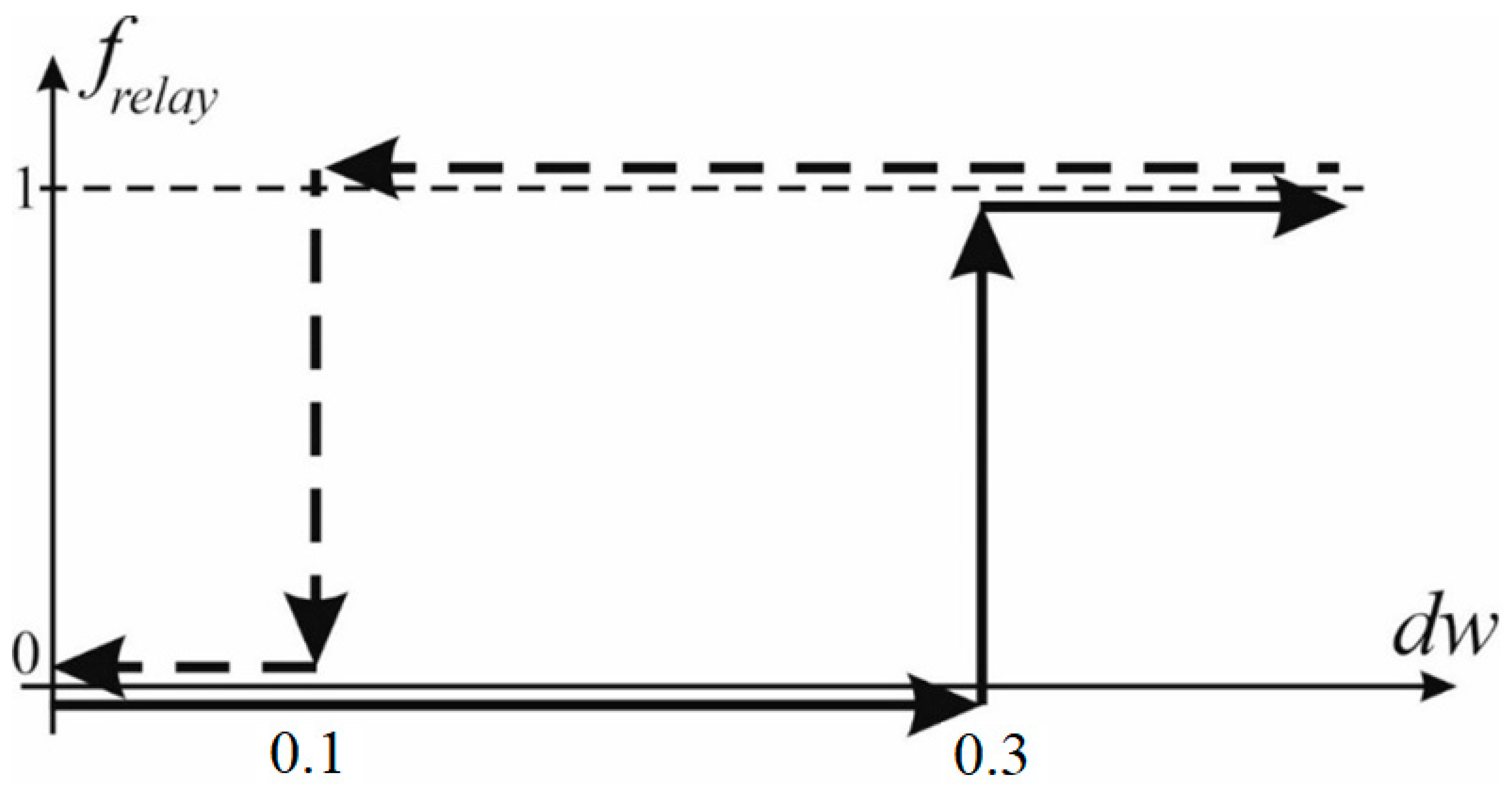
The relay functions f r e l a y 2 and f r e l a y 4 for the left and right driving wheels are defined according to Figure 7.
The wheel slip observer should ensure the optimal slip d w i of driving wheels 0.1 d w i 0.3 . When the diagnostic indicator exceeds 0.3, indicating a potential wheel lockup, the control system should take measures to reduce slip to prevent, among other things, self-excited oscillations.
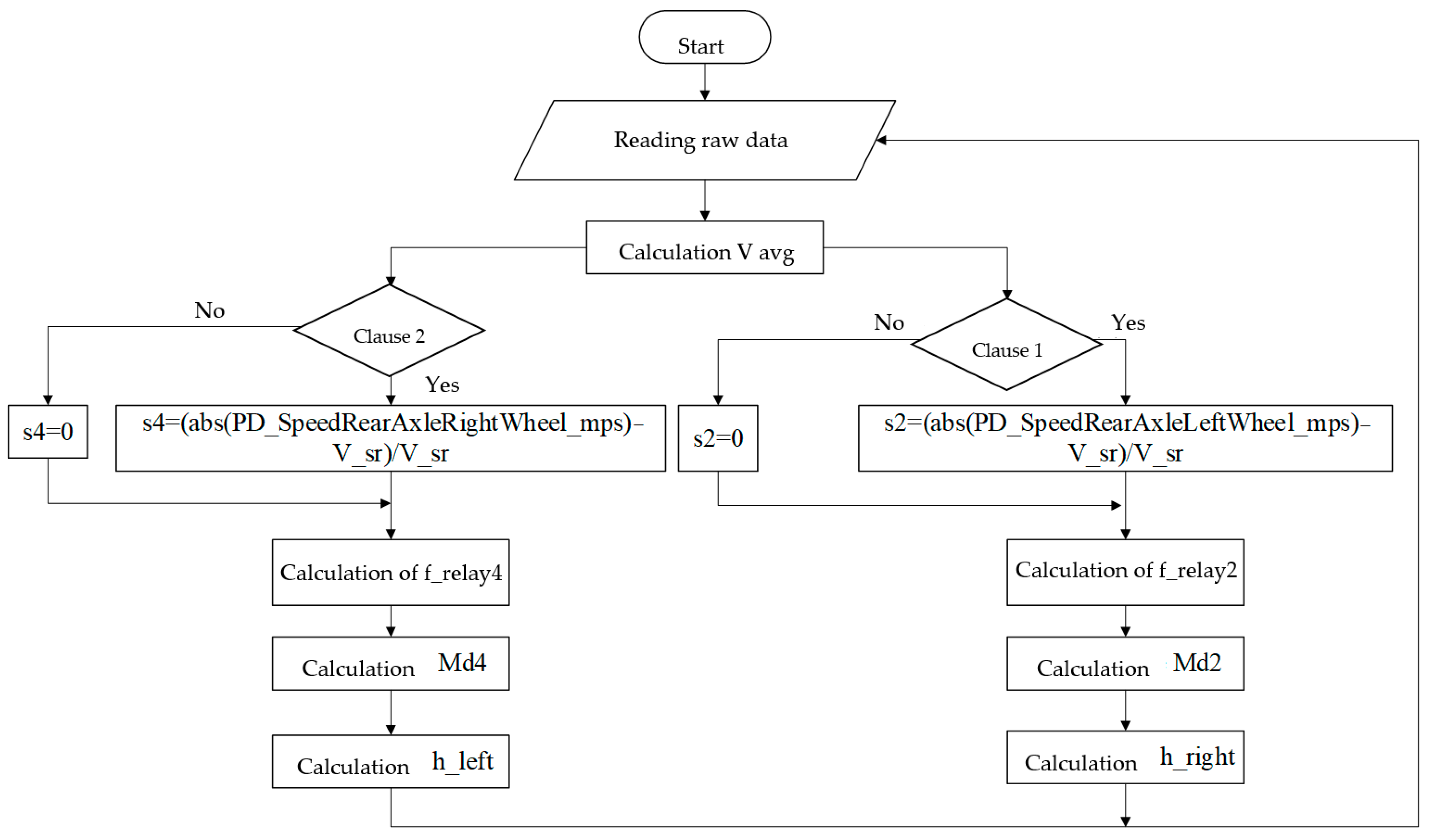
A control algorithm that makes it possible to suppress self-oscillations during increased wheel slip is shown in Figure 8 [43], working as follows:
1.
Read from the sensors the parameters: angular velocities of the rear-driven wheels ω 2 , left and ω 4 right, angular velocities of the front-driven wheels ω 1 , left and ω 3   right, linear speed of the machine, acceleration pedal position h d r , steering wheel rotation angle θ.
2.
Calculate diagnostic signs of slipping d w 2 and d w 4 using Formula (7) and functions f r e l a y 2 and f r e l a y 4 according to Figure 7 for left and right drive wheels.
3.
Evaluate the values of torques M t 2 and M t 4 for the left and right traction motors according to the readings transmitted by the traction inverter.
4.
If functions f r e l a y 2 = 1 or f r e l a y 4 = 1 :
4.1
Calculate control signals u2 or u4
u 2,4 = 0.5 ω k 1 + ω k 3 ω k 2,4 ,   w h e n   ω k 2,4 0 ;   ω k 2,4 > 0.5 ω k 1 + ω k 3 ; u 2,4 = 1 ,   w h e n   ω k 2,4 0.5 ω k 1 + ω k 3 .
4.2
Calculate correction coefficients k2 or k4, allowing to take into account the redistribution of braking torque during curvilinear k 2 = ω k 3 ω k 1 ;   k 4 = ω k 1 ω k 3 ;
4.3
Calculate the required torque for the left u 2 k 2 M t 2 or right u 4 k 4 M t 4 driving wheels; or right u 4 k 4 M t 4 driving wheels;
4.4
Calculate the angular stiffnesses C m 2 and C m 4 using Formula (12):
C m i = M t i ω K i ,   i = 1 ; 2 .
where are the increments of electromagnetic torque estimates M t 2 = M t 2 t j M t 2 t j 1 , M t 4 = M t 4 t j M t 4 t j 1 and wheel angular speed ω k 2 = ω k 2 t j ω k 2 t j 1 , ω k 4 = ω k 4 t j ω k 4 t j 1 ; t j , t j 1 is current and previous times.
4.5
Calculate the minimum values of the self-oscillation damping coefficient K w 2 and K w 4 ;
K w 2 J k C m
4.6
Calculate minimum damping moments M d 2 or M d 4 :
M d = K w ω K f r e l a y
4.7
If f r e l a y 2 = 0 , then K w 2 = 0 or if f r e l a y 4 = 0 , then K w 4 = 0 .
5.
Generate torque settings u 2 k 2 M T 2 + M d 2 for the left traction motor and u 4 k 4 M T 4 + M d 4 for the right traction motor (t).
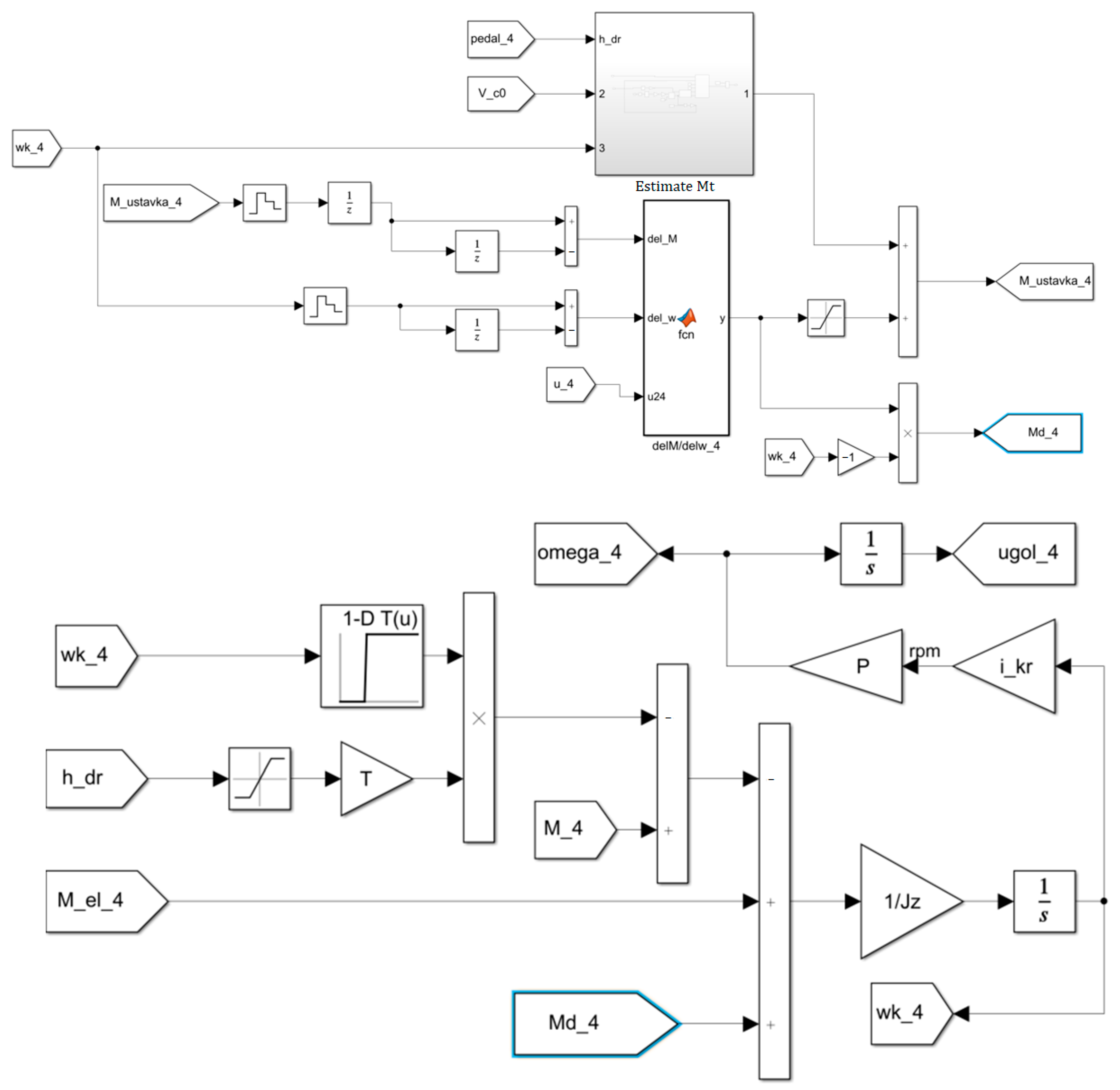
Figure 9 shows a block diagram for implementing the self-oscillation suppression algorithm in MATLAB Simulink.
The result of the algorithm is the traction or regenerative torque settings for the left h_left and right h_right traction electric motors, adjusted to take into account the damping self-oscillation of the torque.
The implementation of the self-oscillation suppression algorithm in MATLAB Simulink is shown in Figure 10.

3. Results

3.1. Simulation of Slip Observer Operation for Suppressing Self-Excited Oscillations

The intensive braking of an electric bus was studied while turning left using a simulation mathematical model in MATLAB Simulink, Figure 11, on the “ice with snow” (with a factor of interaction between the drive and the support base at full slip, μsmax = 0.35) and “dry asphalt” (μsmax = 0.80) support bases [42].
Figure 12 shows the simulation mathematical model of the slip observer in MATLAB Simulink, which allows for building a control system with the self-excited oscillation suppression function.
To study the efficiency and operability of the developed control algorithm for the individual traction drive with the self-excited oscillation suppression function in braking mode, theoretical studies on the motion of an electric bus were performed using simulation mathematical modeling. The motion mode was emergency braking (full pressing of the brake pedal) on a straightway from a speed of 70 km/h with an attempt to maneuver to avoid a collision with an obstacle on asphalt and ice with snow. Combined braking was performed by the activation of mechanical wheel braking mechanisms and the creation of a regenerative moment on the traction motors.
As the algorithm efficiency criteria for the conventional anti-lock braking system (ABS) and the ABS with the self-excited oscillation suppression function, the average relative change ε 01 in the peak values of self-excited oscillations for the angular wheel speed ε 01 ω and the total braking torque on the driving wheel ε 01 M during comparative tests of the electric bus equipped with a conventional ABS and an ABS with the self-excited oscillation suppression function were adopted:
ε 01 = 1 k 01 j = 1 k 01 p j 0 p j 1 p j 0 100 %
where pj0 and pj1 are the j-th peak values of the realization for the electric bus equipped with, respectively, a conventional ABS and an ABS with the self-excited oscillation suppression function; k01 is the number of paired peaks in the realizations.
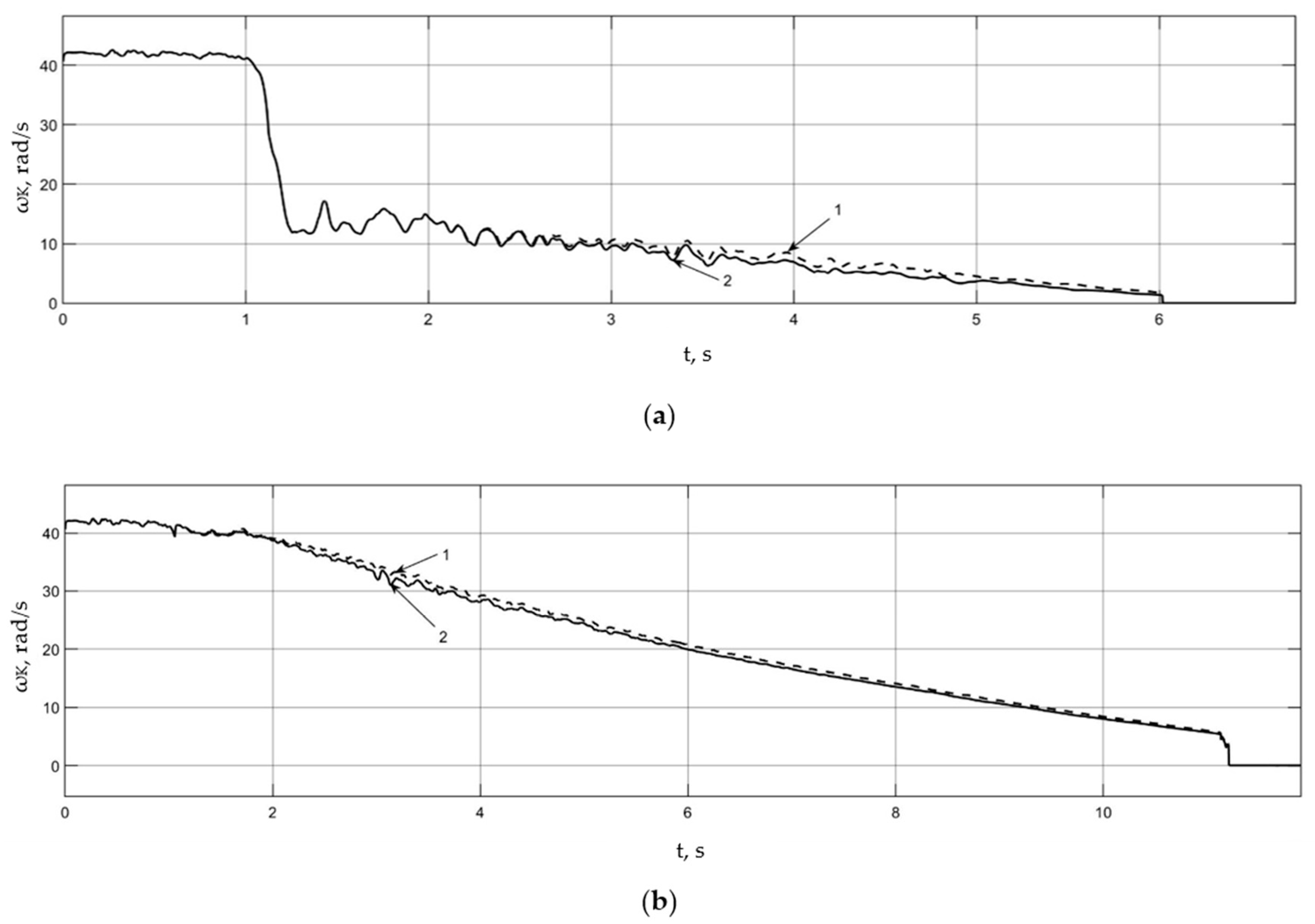
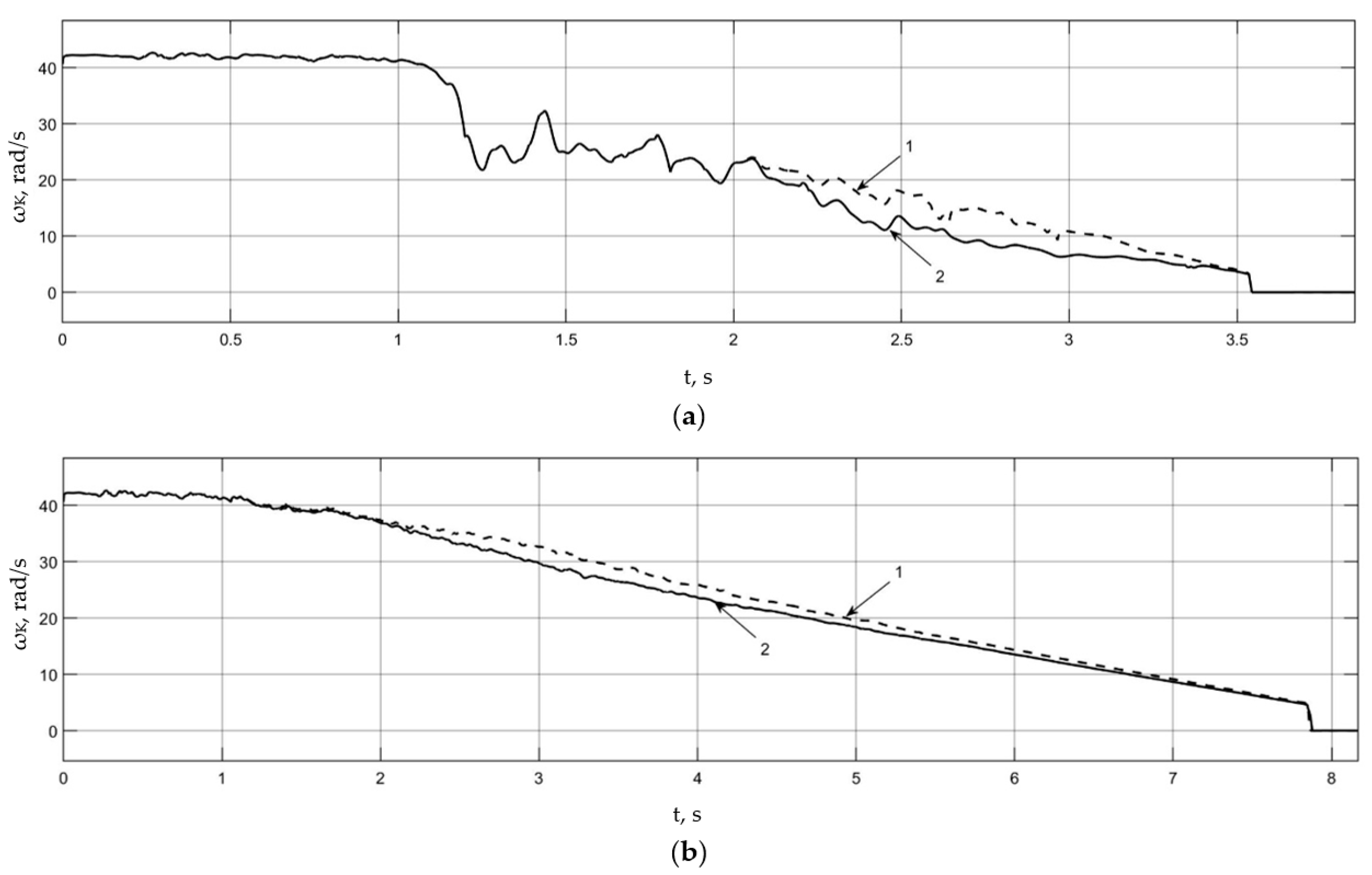
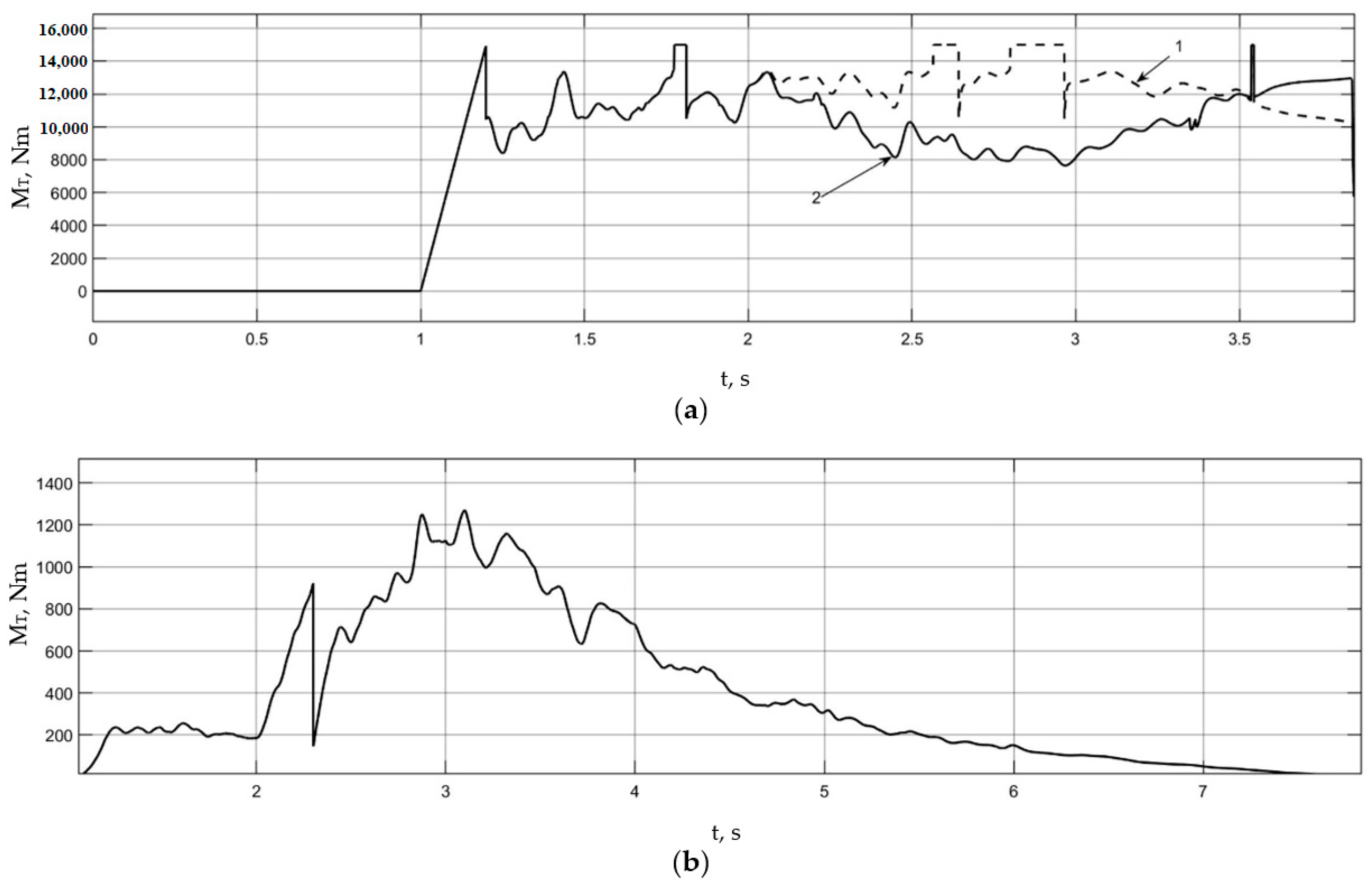
For the case of braking on ice, Figure 13 shows the driving wheel angular speeds for both options, and Figure 14 shows the total braking torques on the driving wheels: 1—left wheel; 2—right wheel.
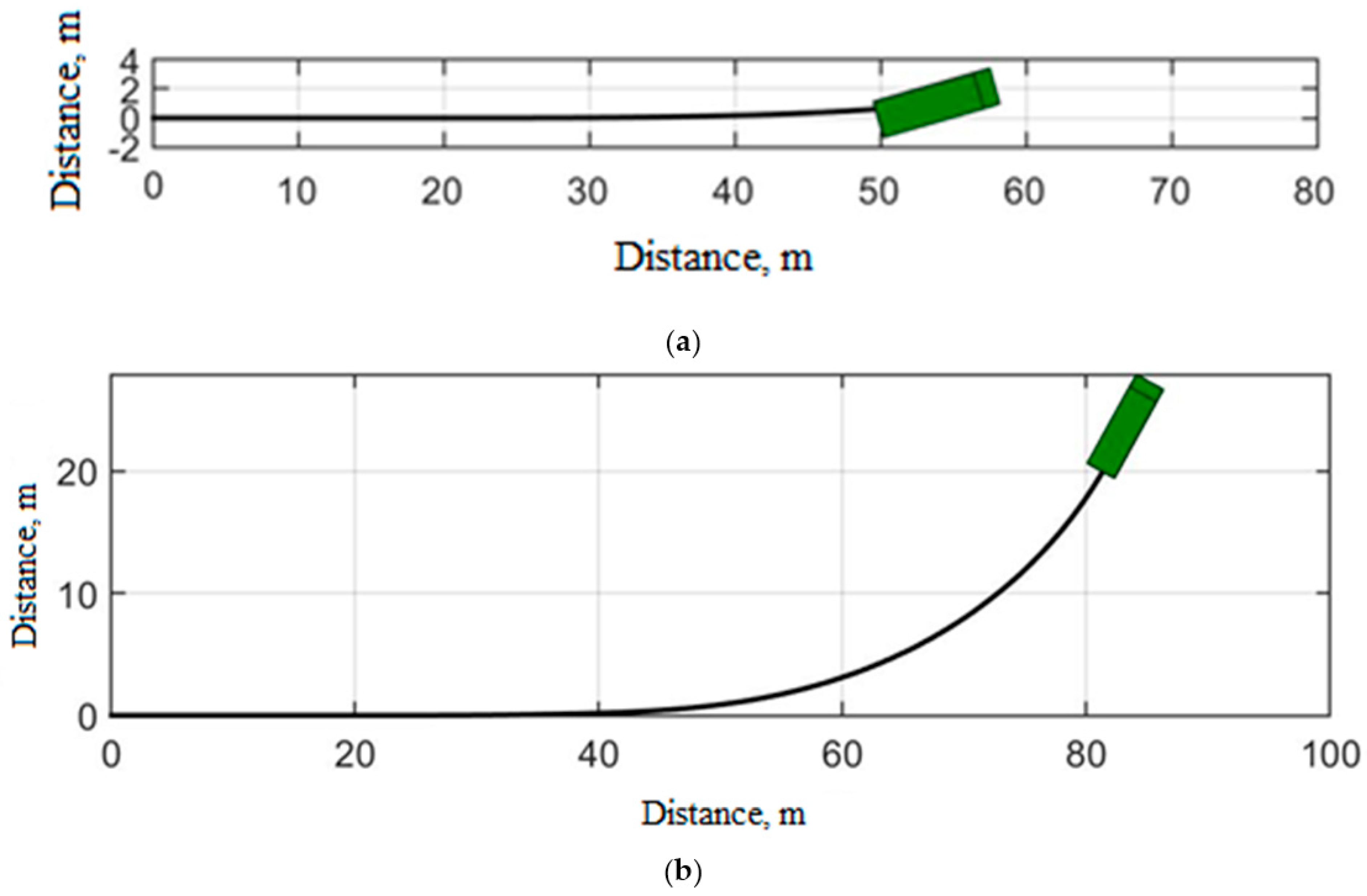
Figure 13 shows that when braking a car on a slippery base when using a conventional classic anti-lock braking system, the rear axle skids (Figure 13a), and the vehicle loses control and is unable to continue the maneuver, which is not observed when using an anti-lock braking system with the function of suppressing self-oscillations (Figure 13b). Thus, when decelerating, controllability is maintained at the required level.
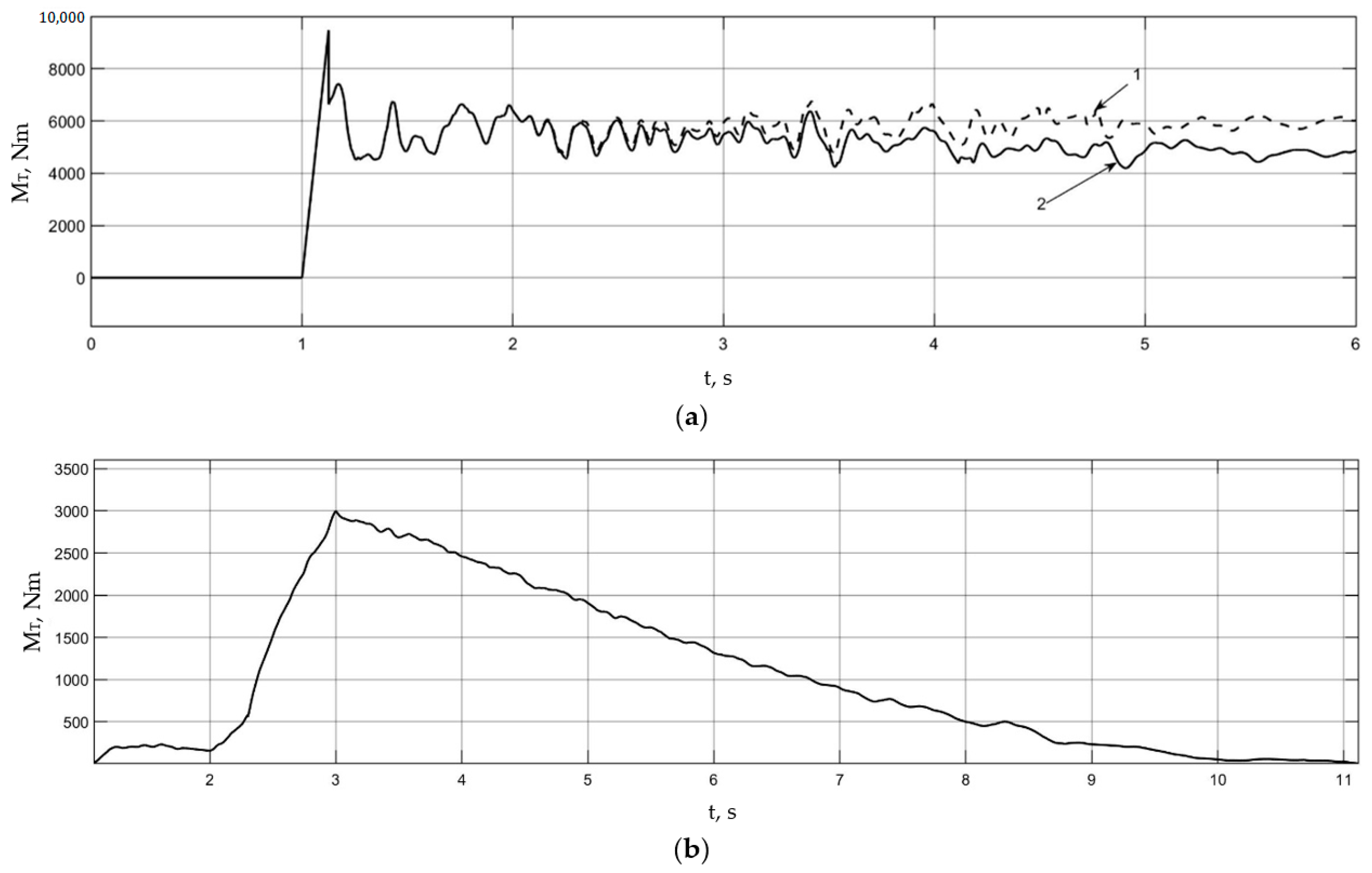
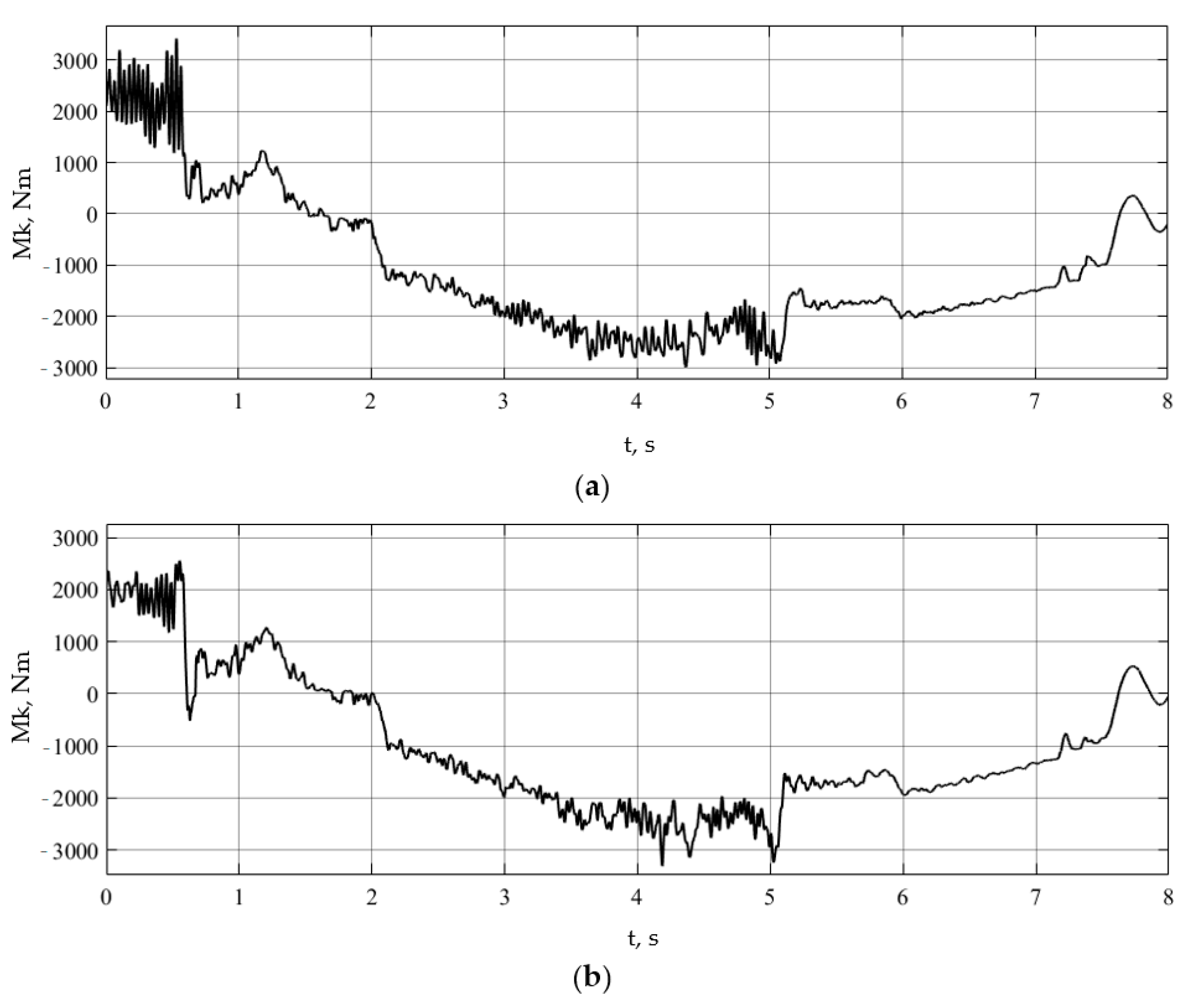
During sharp braking using conventional ABS on a slippery supporting surface, self-oscillatory processes of wheel rotation (Figure 14a) and braking torques (Figure 15a) occur, which leads to a deterioration in the conditions of adhesion of the wheels to the supporting surface and a decrease in controllability and trajectory stability. As a result, the car cannot perform a full collision avoidance maneuver when braking.
For the case of braking on asphalt, Figure 16 shows the trajectories of the machine and Figure 17 shows the angular speeds of the driving wheels for two variants of the system. Figure 18 shows the total braking moments on the drive wheels for both system options: 1—left wheel and 2—right wheel.
In the case of intensive braking combined with a maneuver on asphalt, when the car is equipped with a conventional anti-lock braking system, the rear axle also skids (Figure 16a) and the car loses the ability to turn. In the case of using an anti-lock braking system with the function of suppressing self-oscillations, this phenomenon is not observed (Figure 16b).
An analysis of the presented simulation results of braking on asphalt shows that the comparative results of conventional ABS and ABS with vibration suppression function are the same as in the case of braking on ice and snow. Excitation of oscillatory phenomena is observed for the angular velocities of the wheels (Figure 14) and braking torques (Figure 15) for a car equipped with conventional ABS. When using ABS with the function of suppressing self-oscillations, such phenomena are not detected.

3.2. Experimental Study of the Effectiveness of the System for Suppressing Self-Oscillations during Intense Braking

To confirm the functionality and effectiveness of the self-oscillation suppression function, it is also necessary to additionally conduct full-scale experimental studies, which involve implementing intense decelerations that provoke increased slip.
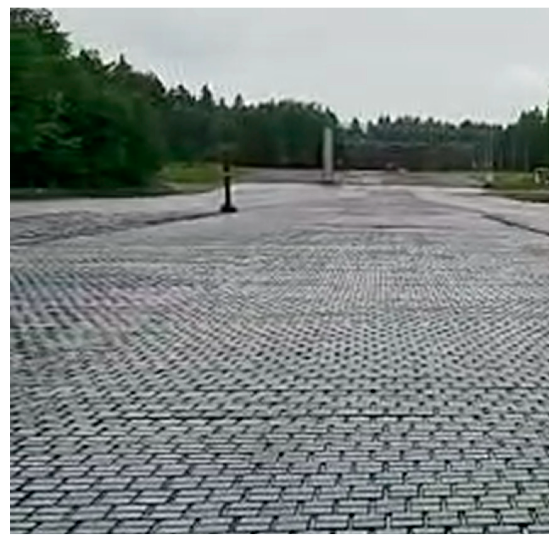
Road conditions were selected based on the implementation of increased slippage of the drive wheels (Figure 19). The tires are inflated to a pressure corresponding to the technical documentation and pre-heated with a run of at least 1 km at a speed of at least 25 km/h. The degree of charge of the traction battery must be sufficient to ensure the necessary dynamics of motion and not affect the traction and speed characteristics of the drive.
Table 1 shows a list of tests to study the effectiveness of the algorithm for suppressing self-oscillations when performing intensive deceleration.
Wet basalt was chosen as the supporting base (Figure 19).

4. Discussion

4.1. Experimental Study of the Effectiveness of the System for Suppressing Self-Oscillations during Intense Braking

To confirm the effectiveness and efficiency of equipping the braking control system with the function of suppressing self-oscillations using the experimental research method, it is necessary to compare the braking processes of a car equipped with the specified function and without it, comparing the implementation of angular velocities, braking torques, and deceleration trajectories.
Before the start of testing, the vehicle accelerates to the required speed, and when entering a support base with a low coefficient of adhesion—wet basalt—intensive braking is carried out, during which the driver presses the brake pedal at maximum speed all the way.
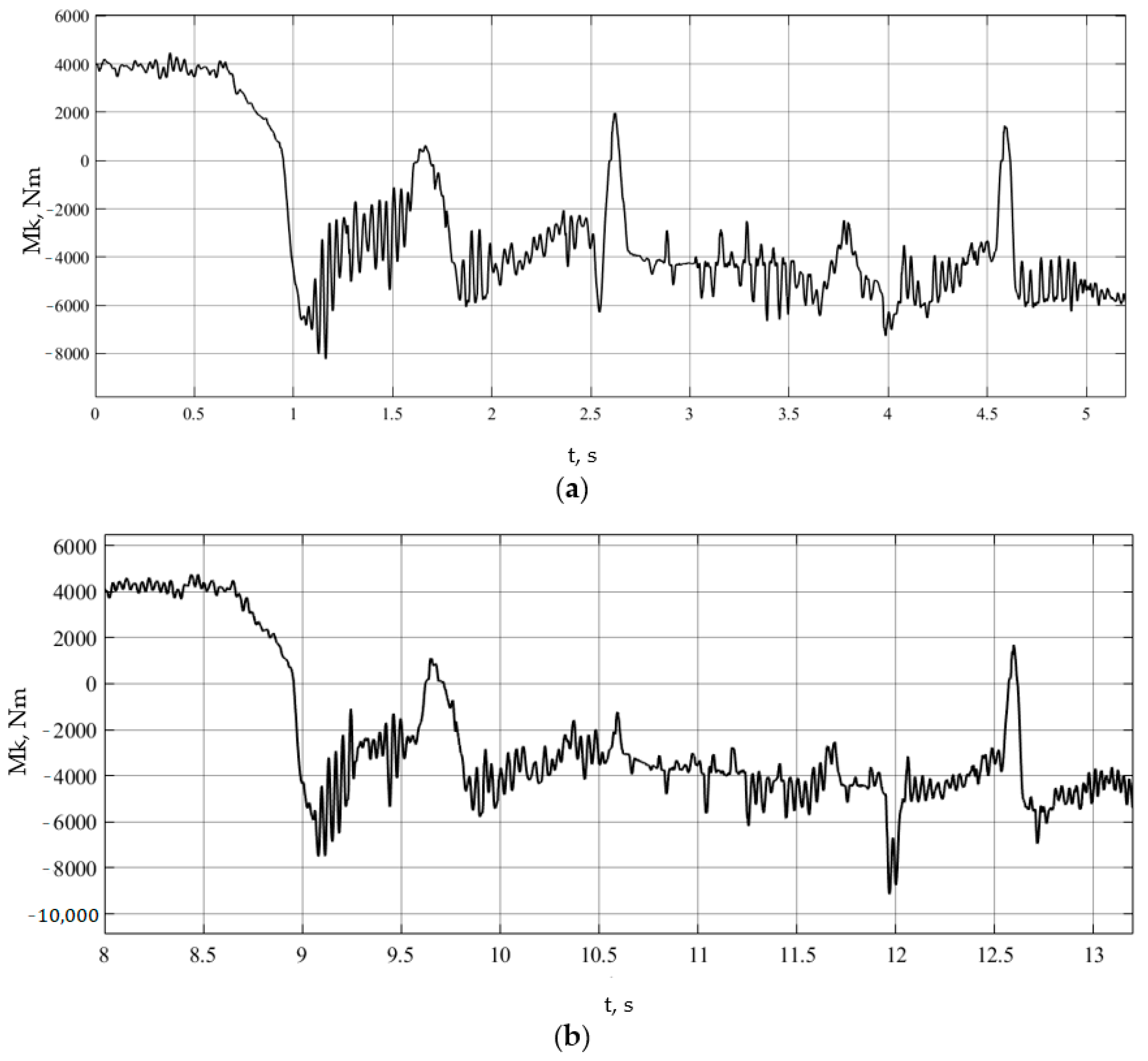
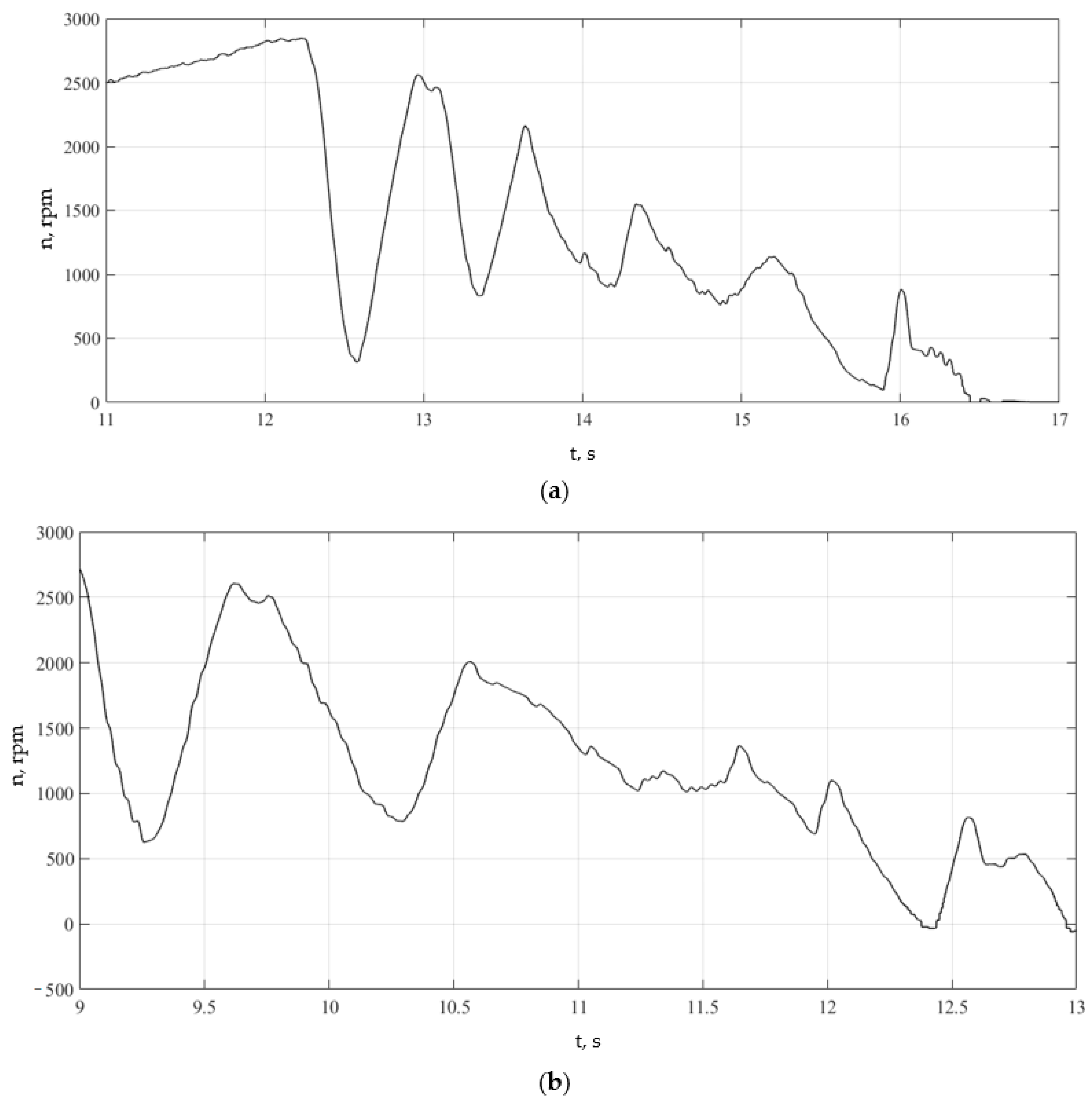
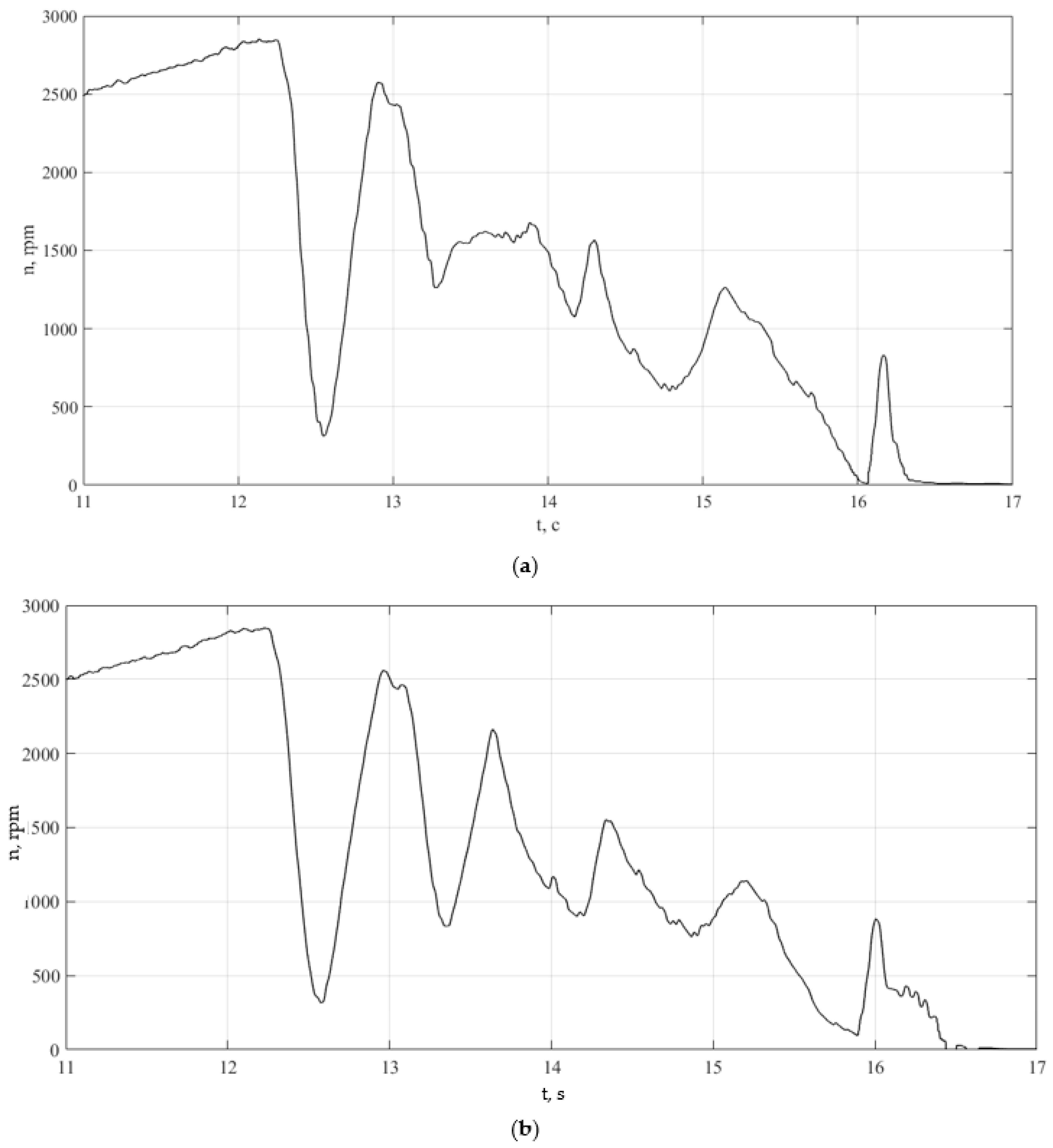
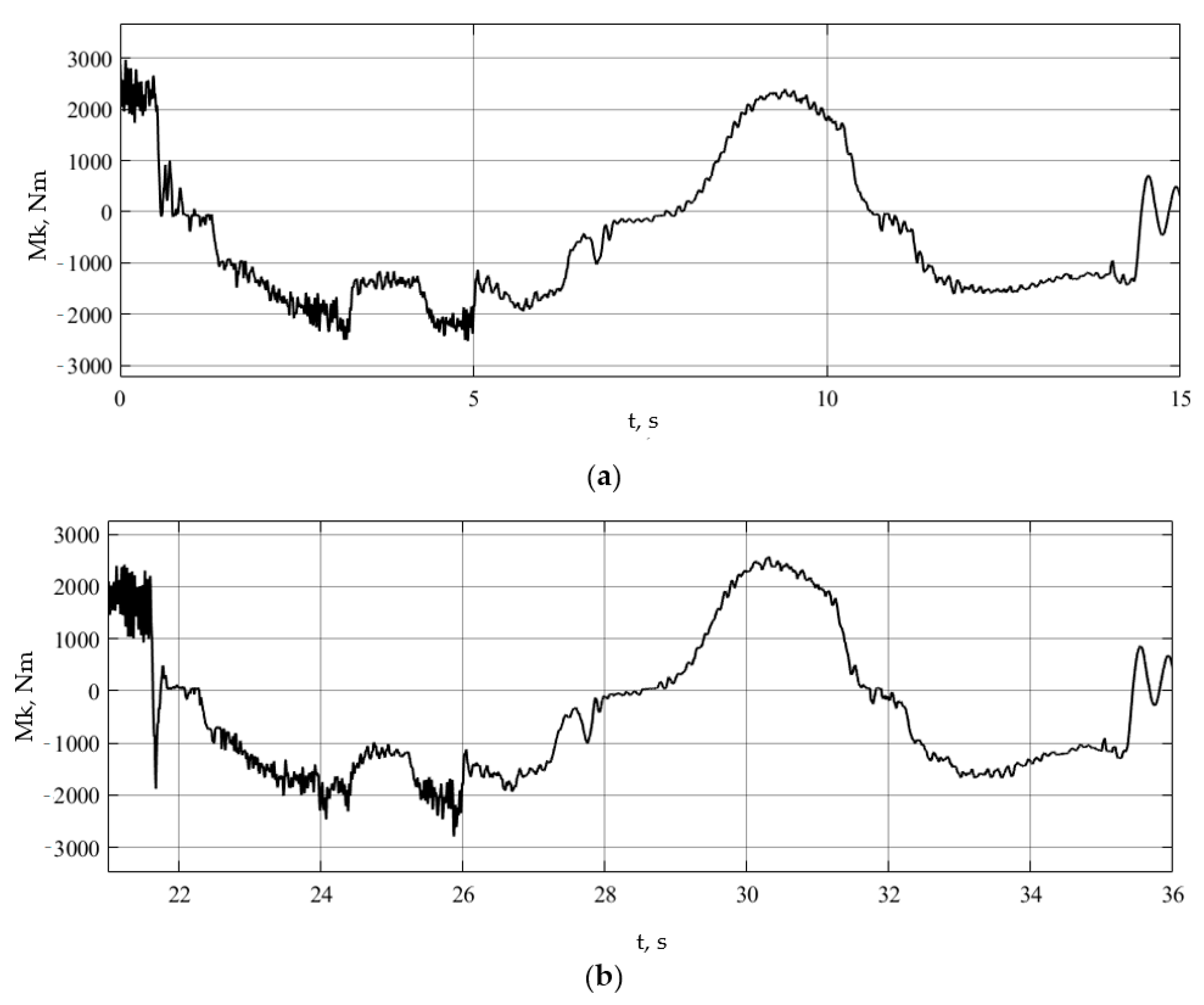
Figure 20, Figure 21, Figure 22, Figure 23, Figure 24 and Figure 25 show the results of the completed runs for a car equipped with conventional ABS, which does not allow suppression of oscillatory phenomena.
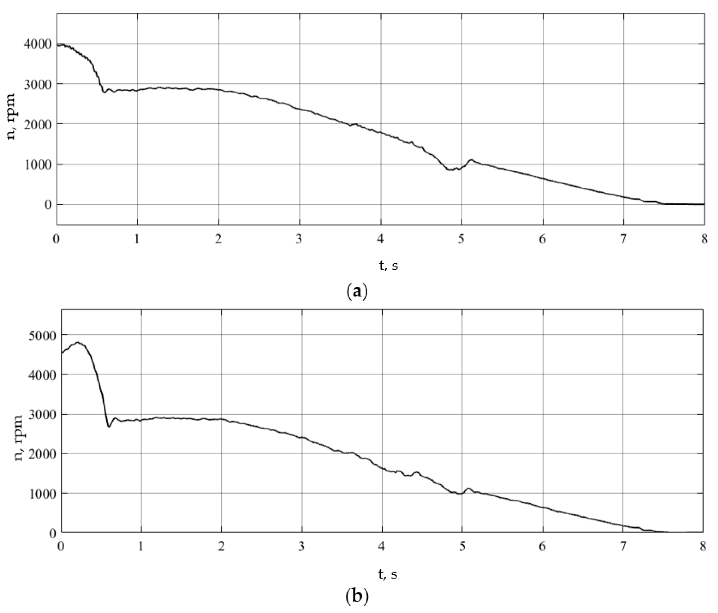
In the above-recorded dependencies, areas of operation of the anti-lock braking system with increased wheel slip are clearly visible. The oscillatory phenomena excited in this case are less intense than in the previous case and are characterized by lower amplitudes, which indicates the effectiveness of the algorithm for suppressing self-oscillatory phenomena. To realize wheel-rotation frequencies in this case, the excitation of self-oscillatory phenomena was not detected.

4.2. Study during Intense Braking with Activated Vibration Suppression System

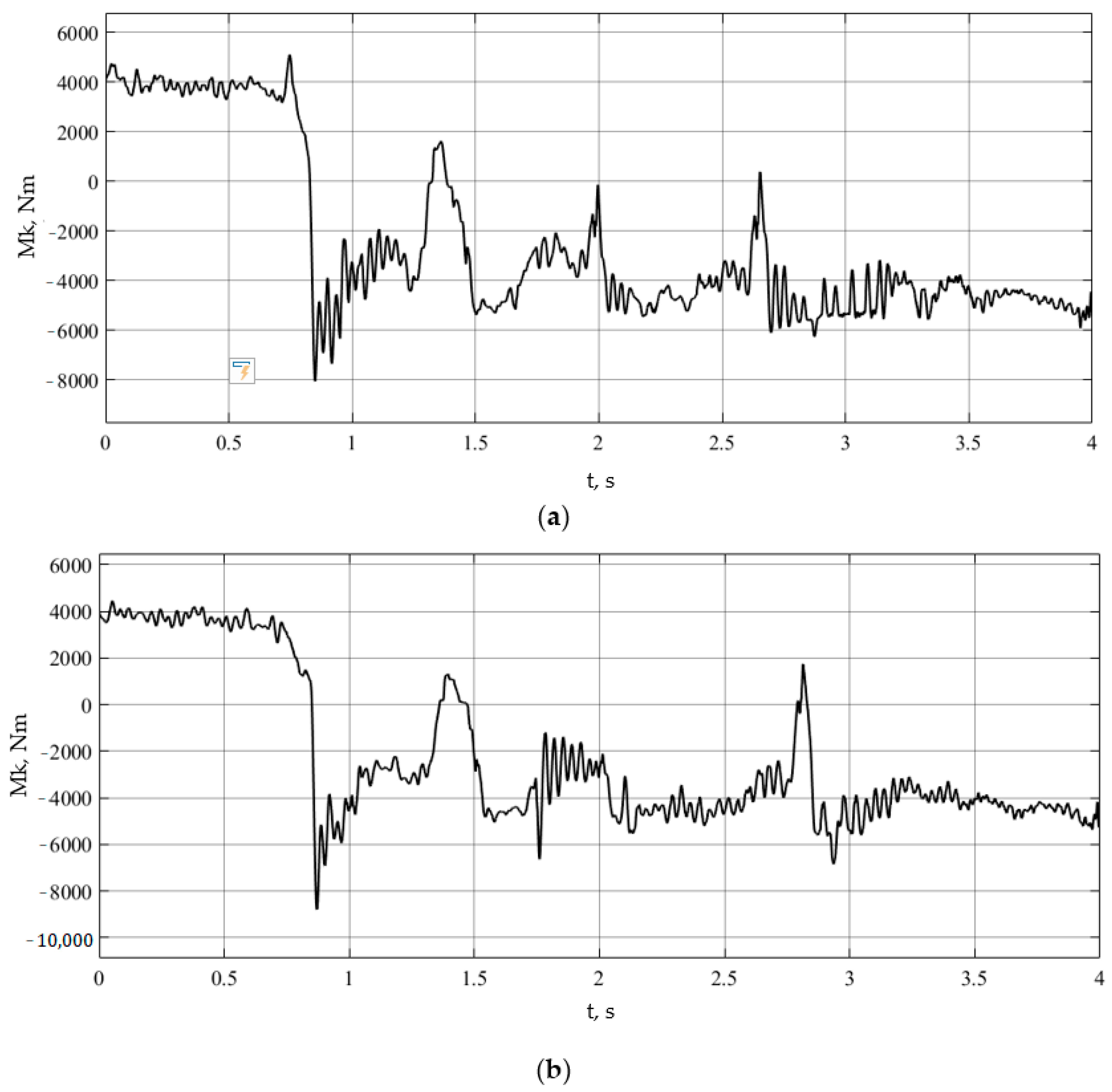
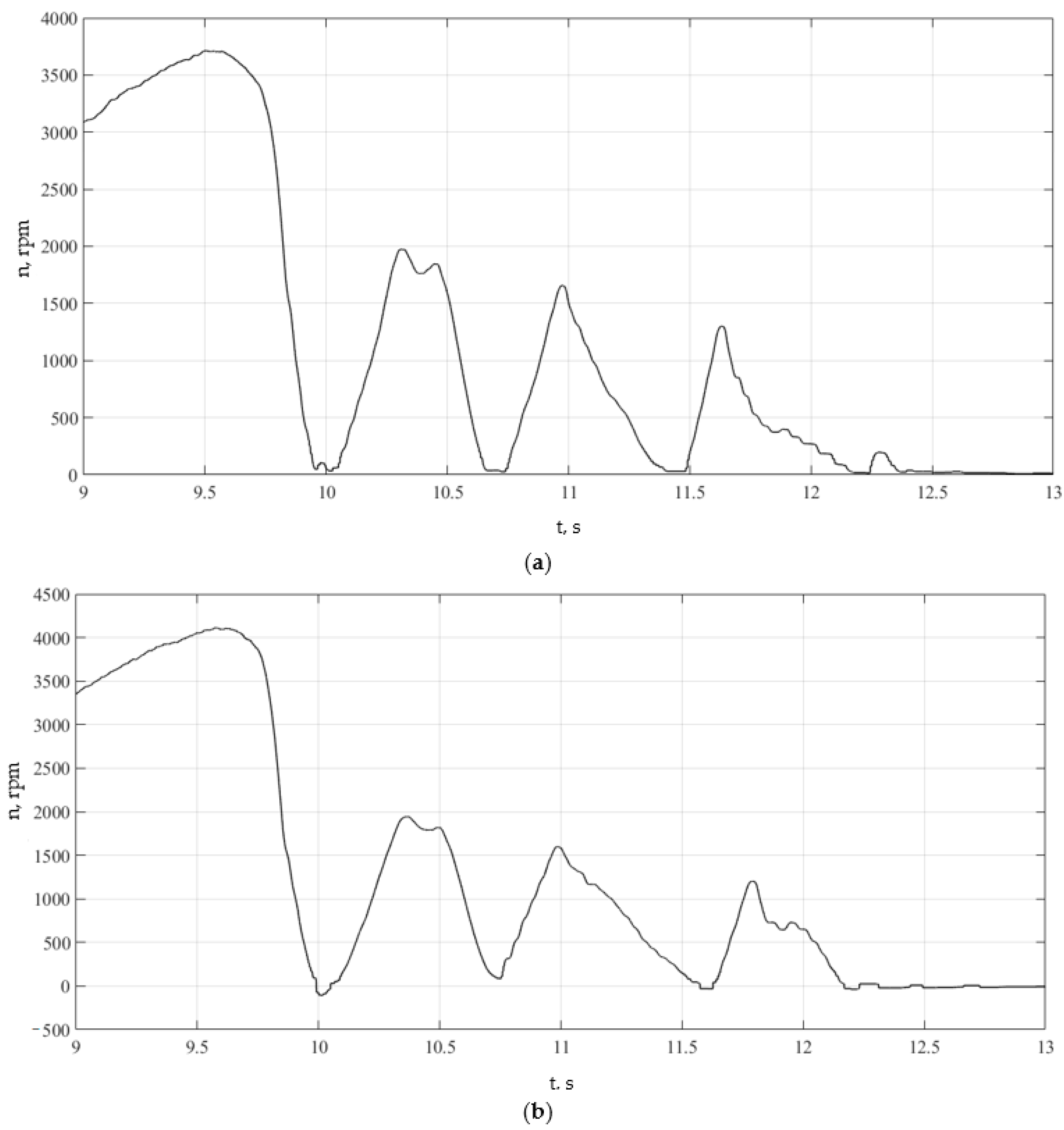
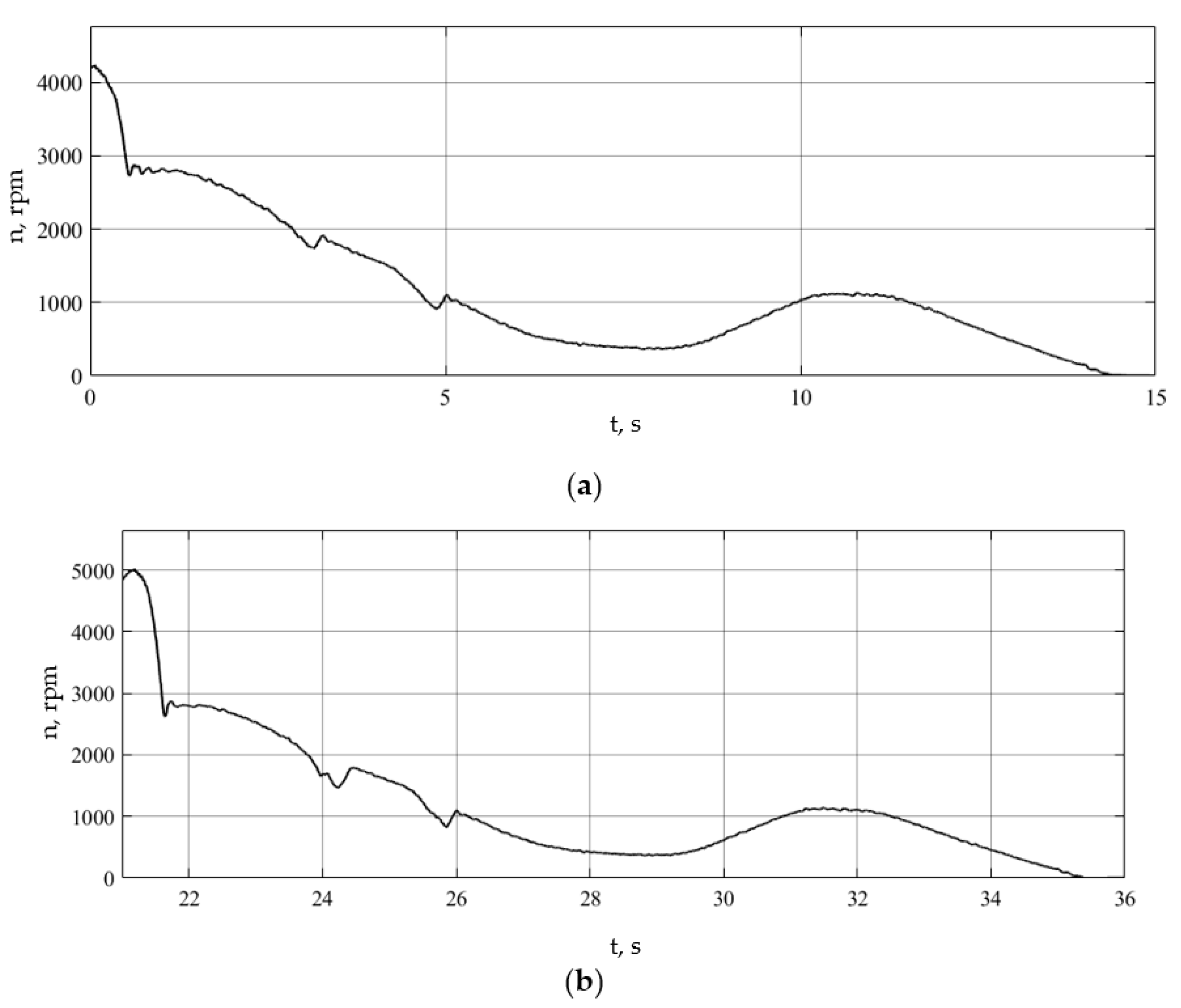
Figure 26, Figure 27, Figure 28, Figure 29, Figure 30 and Figure 31 show the results of the runs performed when studying the emergency deceleration mode on a support base with low adhesion properties for a vehicle equipped with a vibration suppression system.
In the above-recorded dependencies, areas of operation of the anti-lock braking system with increased wheel slip are clearly visible. The oscillatory phenomena excited in this case are less intense than in the previous case and are characterized by lower amplitudes, which indicates the effectiveness of the algorithm for suppressing self-oscillatory phenomena. To implement wheel-rotation frequencies in this case, the excitation of self-oscillating phenomena was not detected.
Analysis of the presented results of experimental studies and simulation modeling of braking shows that the comparative results of the operation of conventional ABS and ABS with the function of suppressing self-oscillations are of a similar nature. If the system does not have a self-oscillation suppression function, oscillatory phenomena for torques are observed. The amplitudes of oscillations are of a similar order. The use of this function makes it possible to reduce the oscillation amplitudes in both cases, which indicates its effectiveness.
Using analytical analyses of differential equations of motion of a wheeled vehicle during deceleration, it was established using the Bendixson criterion that it is possible to excite self-oscillations of the carrier system for translational motion, the rotor of a traction electric motor for rotational motion, as well as for both rotational and translational motion of the wheel. This was also confirmed when using the simulation model of vehicle movement and experimental studies of movement and the possibility of excitation of self-oscillatory phenomena in the contact zone was established; the performance and effectiveness of the algorithm for suppressing self-oscillations in the electromechanical drive system of the driving wheels of a vehicle, which allows us to recommend its use in the development of systems management.
The performance and effectiveness of the algorithm for suppressing self-oscillations in the electromechanical drive system of the driving wheels of a vehicle have been confirmed using simulations of vehicle motion and experimental studies, which makes it possible to recommend its use in the development of control systems. In the case of using ABS on a vehicle when braking on a slippery supporting surface with the function of suppressing self-oscillations, the level of self-oscillations of the angular speeds of rotation of the wheels (Figure 20b) decreased by ε 0 ω = 80 % , the level of total braking torques on the driving wheels (Figure 20b) decreased by ε 0 M t = 96 % .
When using ABS with the self-excited oscillation suppression function on asphalt, the level of self-excited oscillations decreased by ε 0 ω = 98 % for the angular wheel speeds (Figure 10) and by ε 0 M t = 81 % for the total braking torques on the driving wheels (Figure 11). The evasive maneuver during braking was successfully completed, indicating improved controllability and road-holding ability of the electric bus with the ABS with the self-excited oscillation suppression function when braking on slippery support bases. Herewith, dynamic loads in the drive also decrease, improving the reliability of the elements due to reducing peak values of regenerative torques and the control system operation. The simulation mathematical modeling of the slip observer operation in braking mode shows its operability. The practical value of the study is determined by the possibility of using the proposed control laws for developing the traction drive control system for vehicles.

5. Conclusions

The study established that the use of an algorithm for suppressing self-oscillations in the control system makes it possible to reduce the values of maximum amplitudes by 6 times and average amplitudes by 3 to 3.5 times while excluding changes in the sign of the moment during intense decelerations of the vehicle.
Based on the study, we can conclude that during intense braking on a support base with low adhesion properties (ice, ice with snow, wet asphalt, etc.) for a vehicle not equipped with a self-oscillation suppression algorithm, the average amplitudes of torque oscillations are in the range from 1850 to 2500 Nm, with a maximum amplitude value in the range from 6000 to 8500 Nm.
When the vehicle control system is equipped with an algorithm for suppressing self-oscillations during intense braking, the average amplitudes of torque oscillations are in the range from 500 to 750 Nm, with maximum amplitude values in the range from 1000 to 1500 Nm.
The practical value of the study lies in the possibility of using the proposed control laws to develop a control system for the traction drive of transport vehicles.

Author Contributions

Conceptualization, S.S.S.; Methodology, A.V.K. (Alexander V. Klimov); Software, Y.M.F.; Validation, B.K.O. and S.S.S.; Formal analysis, A.V.K. (Alexander V. Klimov) and E.A.D.; Investigation, A.V.K. (Alexander V. Klimov), B.K.O. and Y.M.F.; Resources, V.R.A. and V.S.E.; Data curation, A.V.A.; Writing—original draft, D.A.M.; Writing—review & editing, D.A.N. and D.A.M.; Project administration, A.V.K. (Andrey V. Keller). All authors have read and agreed to the published version of the manuscript.

Funding

This research was funded by the Ministry of Science and Higher Education of the Russia Federation within the framework of the project “Development of a mathematical model of chassis operation (transmission, chassis and control mechanisms) in static and dynamic states and creation of a digital twin of a passenger car platform on its basis” (code: FZRR-2023-0007).

Data Availability Statement

The original contributions presented in the study are included in the article, further inquiries can be directed to the corresponding author.

Conflicts of Interest

Alexander V. Klimov, Baurzhan K. Ospanbekov, Akop V. Antonyan, Viktor R. Anisimov, and Egor A. Dvoeglazov are employees of LLC KAMAZ Innovation Center. The paper reflects the views of the scientists and not the company.

References

  1. Vilke, V.G.; Shapovalov, I.L. Self-Excited Oscillations in the Process of Car Braking. Vestnik MGU. Ser. 1. Math. Mech. 2015, 4, 33–39. [Google Scholar]
  2. Svetlitskii, V.A. Random Oscillations of Mechanical Systems; Mashinostroenie: Moscow, Russia, 1976; 250p. [Google Scholar]
  3. Kruchinin, P.A.; Magomedov, M.K.; Novozhilov, I.V. Mathematical Model of a Car Wheel in Anti-Lock Braking Modes. J. Bull. Russ. Acad. Sciences. Solid Body 2001, 6, 63–69. [Google Scholar]
  4. Awrejcewiez, J.; Dzyubak, L.; Grehori, C. Estimation of chaotic and regular (stick-slip and ship-slip) oscillations exhibited by coupled oscillations with dry friction. Nonlinear Dyn. 2005, 42, 383–394. [Google Scholar] [CrossRef]
  5. Pascal, M. Dynamics and stability of a two degrees of freedom oscillator with an elastic stop. J. Comput. Nonlinear Dyn. 2006, 1, 94–102. [Google Scholar] [CrossRef]
  6. Shin, K.; Brennan, M.J.; Oh, J.-E.; Harris, C.J. Analysis of disk brake noise using a two-degrees-of-freedom model. J. Sound Vib. 2002, 254, 837–848. [Google Scholar] [CrossRef]
  7. Kolesnikov, K.S. Self-Excited Oscillations of Controlled Wheels; Gosudarstvennoe Izdatelstvo Tekhniko-Teoreticheskoy Literatury: Moscow, Russia, 1955; 356p. [Google Scholar]
  8. Vilke, V.G.; Shapovalov, I.L. Self-Oscillations During Car Braking. Mosc. Univ. Mech. Bull. 2015, 70, 142–146. [Google Scholar]
  9. Shapovalov, I.L. Investigation of Self-Excited Oscillations of Mechanical Systems in Variables Action–Angle. PhD Thesis, Lomonosov Moscow State University, Moscow, Russia, 2015. [Google Scholar]
  10. Kotiev, G.O.; Padalkin, B.V.; Kartashov, A.B.; Diakov, A.S. Designs and development of Russian scientific schools in the field of cross-country ground vehicles building. ARPN J. Eng. Appl. Sci. 2017, 12, 1064–1071. [Google Scholar]
  11. Ergin, A.A.; Kolomejtseva, M.B.; Kotiev, G.O. Antiblocking control system of the brake drive of automobile wheel. Prib. Sist. Upr. 2004, 9, 11–13. [Google Scholar]
  12. Kaldas, M.; Soliman, A. An Investigation of Anti-Lock Braking System for Automobiles. In Proceedings of the SAE 2012 World Congress & Exhibition, Detroit, MI, USA, 24–26 April 2012. [Google Scholar]
  13. Sun, C.; Pei, X. Development of ABS ECU with Hardware-in-the-Loop Simulation Based on Labcar System; SAE International: Warrendale, PA, USA; Warwick University: Warwick, UK, 2016. [Google Scholar]
  14. Sabbioni, E.; Cheli, F.; d’Alessandro, V. Politecnico di Milano Analysis of ABS/ESP Control Logics Using a HIL Test Bench; SAE International: Warrendale, PA, USA; Warwick University: Warwick, UK, 2016. [Google Scholar]
  15. Hart, P.M. Review of Heavy Vehicle Braking Systems Requirements (PBS Requirements). Draft Report. 24 April 2003. Available online: https://trid.trb.org/View/1407752 (accessed on 28 April 2024).
  16. Marshek, K.M.; Guderman, J.F.; Jonson, M.J. Performance of Anti-Lock Braking System Equipped Passenger Vehicles Part I: Braking as a Function of Brake Pedal Application Force. In Proceedings of the SAE 2002 World Congress, Detroit, MI, USA, 4–7 March 2002. [Google Scholar]
  17. Zhileikin, M.M. Investigation of Autooscillatory Processes in the Zone of Interaction of an Elastic Tire with a Hard Bearing Base. Proc. High. Educ. Inst. Mech. Eng. 2021, 10, 3–15. [Google Scholar]
  18. Afanasyev, B.A.; Belousov, B.N.; Gladov, G.I.; Polungyan, A.A. Designing All-Wheel Drive Wheeled Vehicles: Textbook. Textbook for universities; Izd-vo MGTU im. G. E. Baumana: Moscow, Russia, 2008; Volume 1. [Google Scholar]
  19. Afanasyev, B.A.; Zheglov, L.F.; Zuzov, V.N.; Polungyan, A.A. Designing All-Wheel Drive Wheeled Vehicles. Textbook for Universities; Izd-vo MGTU im. G.E. Baumana: Moscow, Russia, 2008; Volume 2. [Google Scholar]
  20. Beloutov, G.S.; Klochkov, E.S. Combined method for calculating transients in transmissions. Def. Technol. 1984, 1, 45–48. [Google Scholar]
  21. Zhuchkov, M.G.; Korolkov, R.N.; Petrov, O.S. Calculation of the Durability of Transmissions of Military Tracked Vehicles; Isacov, P.P., Ed.; TSNII of Information: Moscow, Russia, 1987; 334p. [Google Scholar]
  22. Grishkevich, A.I. Designing Car Transmissions: Handbook. Mashinostroenie: Moscow, Russia, 1984; 423p. [Google Scholar]
  23. Algin, V.B.; Drobyshevskaya, O.V.; Sorochan, V.M.; Uspenskiy, A.A. Schematization and dynamic calculation of a mobile machine. Systems with variable structure. Mech. Mach. Mech. Mater. 2008, 2, 16–24. [Google Scholar]
  24. Algin, V.B. Dynamics of Multimass Systems of Machines with Changing States of Friction Components and Directions of Power Flows. Mech. Mach. Mech. Mater. 2014, 4, 21–32. [Google Scholar]
  25. Taratorkin, A.I. Scientific Methods for Reducing the Dynamic and Vibration Load of Power Transmissions of Wheeled and Tracked Vehicles by Varying Modal Properties. Ph.D. Dissertation, Centre For Automotive Vehicle Testing And Refinement (FSUE «NAMI»), Moscow, Russia, 2021. The degree inTechnical Sciences/Taratorkin Alexander Igorevich. p. 377. [Google Scholar]
  26. Prokopyev, M.V. Method for Assessing Frictional Self-Excited Oscillations in a Transmission When Starting a Passenger Car. PhD Thesis, Togliatti State University, Togliatti, Russia, 2002; 137p. [Google Scholar]
  27. Salamandra, K.B.; Korendyasev, G.K. To the problem of self-excited oscillations of a transmission with an automatic transmission. In Proceedings of the Mechanical Engineering and Innovation, Conference of Young Scientists and Students (MICMUS-2017), Moscow, Russia, 6–8 December 2017; Institute of Machine Science, A.A. Blagonravov RAS: Moscow, Russia, 2018; pp. 327–330. [Google Scholar]
  28. Myasishchev, D.G.; Vashutkin, A.S.; Lorents, A.S. Reducing the resonance of relaxation self-excited oscillations of wheel brake mechanisms of timber trucks. Izv. Vyssh. Uchebn. Zaved. Les. Zh. 2016, 4, 112–120. [Google Scholar]
  29. Zhileikin, M.M.; Sirotin, P.V.; Nosikov, S.S.; Pulyaev, N.N. Method for detecting loss of stability of tractor movement when implementing tractive effort on a trailer or a coupled unit. Trakt. Sel’khozmashiny 2023, 90, 39–48. [Google Scholar]
  30. Grabar, I.G.; Opanasyuk, E.G.; Begersky, D.B.; Opanasyuk, O.E. Determination of the conditions for the onset of self-oscillatory processes in the contact of a pneumatic tire model with loose soil. Visnyk SevNTU 2011, 121, 139–142. [Google Scholar]
  31. KAMAZ. Characteristics of the KAMAZ 6282 Electric Bus. PJSC KAMAZ: Naberezhnye Chelny, Russia. Available online: https://kamaz.ru/upload/bus/%D0%AD%D0%BB%D0%B5%D0%BA%D1%82%D1%80%D0%BE%D0%B1%D1%83%D1%81%20KAMAZ-6282.pdf (accessed on 15 October 2022).
  32. Klimov, A.V.; Ospanbekov, B.K.; Keller, A.V.; Shadrin, S.S.; Makarova, D.A.; Furletov, Y.M. Research into the Peculiarities of the Individual Traction Drive Nonlinear System Oscillatory Processes. World Electr. Veh. J. 2023, 14, 316. [Google Scholar] [CrossRef]
  33. Klimov, A.V. Oscillatory Processes in a Nonlinear System of an Individual Electric Traction Drive. Gruzovik 2023, 7, 19–24. [Google Scholar] [CrossRef]
  34. Klimov, A.V.; Antonyan, A.V. Study of the features of oscillatory processes in a nonlinear system of an individual traction drive of an electric bus. Her. MSTU MAMI 2023, 17, 87–96. [Google Scholar]
  35. Klimov, A.V. Traction Control System with Wheel Anti-Skid Function for Traction Operation. Tr. Nami 2023, 3, 44–56. [Google Scholar] [CrossRef]
  36. Kuznetsov, A.P.; Kuznetsov, S.P.; Ryskin, N.M. Nonlinear Oscillations; Fizmatlit: Moscow, Russia, 2002. [Google Scholar]
  37. Kryukov, B.I. Forced Oscillations of Significantly Nonlinear Systems; Mashinostroenie: Moscow, Russia, 1984. [Google Scholar]
  38. Nechorkin, V.I. Lectures on the Fundamentals of Vibration Theory: Textbook; Nizhny Novgorod University: Nizhny Novgorod, Russia, 2011. [Google Scholar]
  39. Blehman, I.I. (Ed.) Vibrations in Technology: Handbook; Mashinostroenie: Moscow, Russia, 1979; Volume 2. [Google Scholar]
  40. Gorelov, V.V.; Zhileikin, M.M.; Lovtcov, A.N.; Shinkarenko, V.A. Control law with the function of active safety systems for electromechanical transmissions of multi-axle wheeled vehicles. Izv. Vyssh. Uchebn. Zaved. Mashinostr. 2013, 9, 56–66. [Google Scholar]
  41. Zhileykin, M.M.; Zhurkin, M.M. Anti-lock braking system algorithm with anti-skid function for two-axle vehicles with one driving axle. Her. MSTU MAMI 2020, 1, 51–56. [Google Scholar] [CrossRef]
  42. Zhileykin, M.M.; Kotiev, G.O. Modeling of Vehicle Systems: Textbook; Bauman Moscow State Technical University: Moscow, Russia, 2020; ISBN 978-5-7038-5351-1. [Google Scholar]
  43. Klimov, A.V.; Ospanbekov, B.K.; Zhileikin, M.M. Method of Controlling an Individual Traction Electric Drive of the Driving Wheels of a Multi-Wheeled Vehicle. Patent No. 2797069 C1, 31 May 2023. Russian Federation, IPC B60K 17/12, B60L 15/20, B60L 3/10. No. 2023103483; Application 02/16/2023: Publ. 05/31/2023/; applicant Public Joint Stock Company “KAMAZ”. Available online: https://patents.google.com/patent/RU2797069C1 (accessed on 17 June 2024).
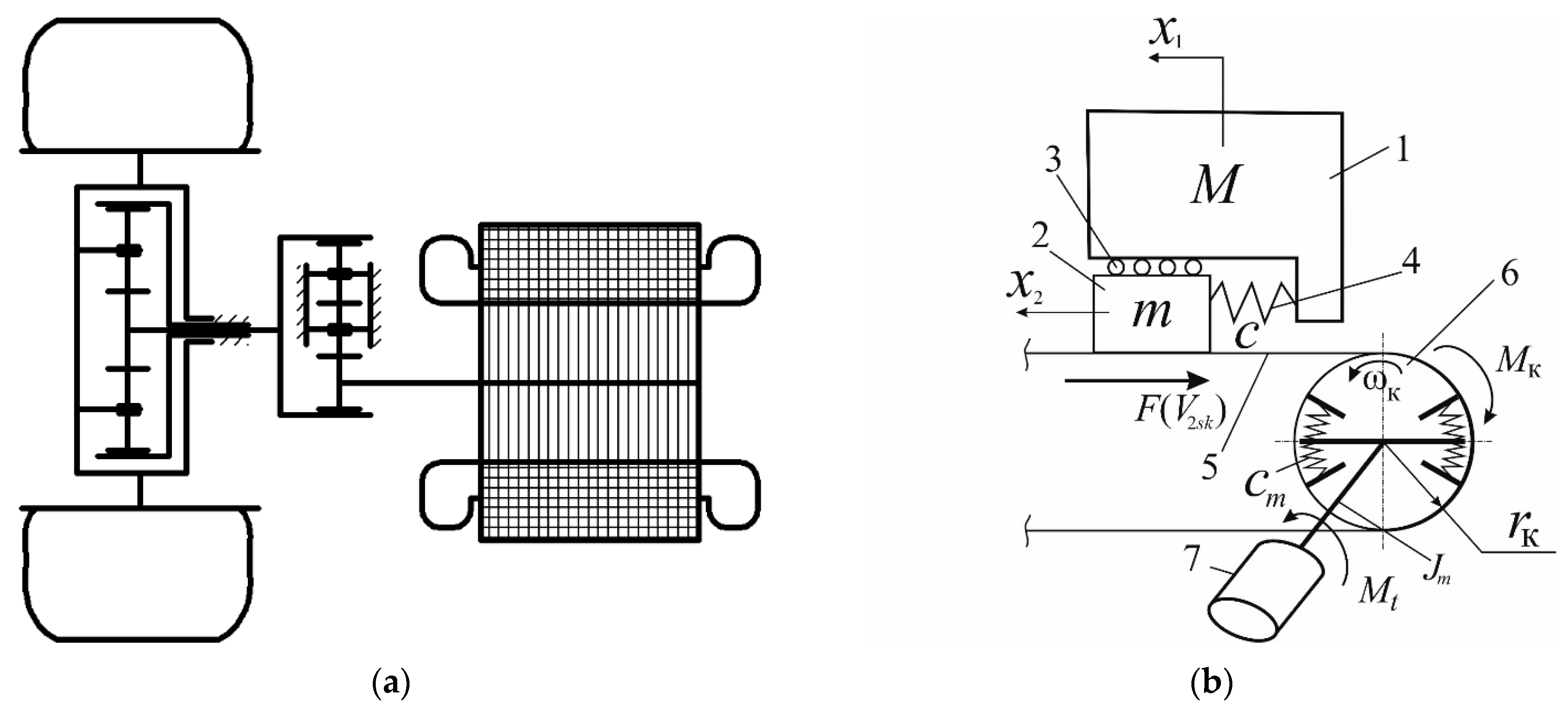
Figure 1. Drive scheme (a) and elastic-tire–solid-support-base interaction scheme (b): 1—mass M of the cushioned vehicle parts attributed to the wheel; 2—the wheel mass m; 3—rollers; 4—spring; 5—support base; 6—rolling wheel; 7—traction motor (TM); c—spring stiffness; x1, x2—longitudinal displacements of masses 1 and 2, respectively; F(V2sk)—friction force depending on the wheel slip speed V2sk relative to the support base; ωK—angular wheel speed; rK—distance from the wheel center to the support base; Mt—braking torque developed by the TM; cm—angular ‘electromagnetic stiffness’ of the synchronous TM with permanent magnets; Jm—inertia moment of the motor’s rotating parts, referred to the rotor; MK—braking torque developed by the wheel brake mechanism.
Wevj 15 00340 g001
Figure 2. Kistler RoaDyn strain gauge wheels.
Wevj 15 00340 g002
Figure 3. Window of programs for data analysis: (a) Vector CANoe; (b) MatLab Simulink.
Wevj 15 00340 g003
Figure 4. Changes in TM torques, wheel and rotor angular speeds, and TM currents over time during acceleration to 20 km/h and subsequent combined braking. Reprinted from Ref. [32].
Wevj 15 00340 g004
Figure 5. Plane design scheme of a two-axle vehicle: l1, l2—distances from the center of mass to the front and rear axles; L—wheelbase; jx, jy—projections of the linear acceleration of the center of mass on the vehicle body-related coordinate system axes; ωz—angular speed of rotation around the vertical axis; Θ1—wheelbase steering angle; V1, V2—speed vectors of the front and rear axle centers; Vc—speed vector of the center of mass.
Wevj 15 00340 g005
Figure 6. Design scheme for determining the current linear speed of the vehicle’s wheel centers during braking.
Wevj 15 00340 g006
Figure 7. Relay function diagram of the slip and self-excited oscillation prevention system.
Wevj 15 00340 g007
Figure 8. Control algorithm (block diagram).
Wevj 15 00340 g008
Figure 9. Block diagram for implementing the self-oscillation suppression algorithm in MATLAB: Condition 1: abs (PD_SpeedRearAxleLeftWheel_mps) > Vagv && Vagv ~= 0; Condition 2: abs (PD_SpeedRearAxleRightWheel_mps) > abs(Vavg) && Vavg ~= 0.
Wevj 15 00340 g009
Figure 10. Implementation of the self-oscillation suppression algorithm in MATLAB Simulink: PD_SpeedFrontAxleLeftWheel_mps—signal about the value of the linear speed of the front left wheel, m/s; PD_SpeedFrontAxleRightWheel_mps—signal about the value of the linear speed of the front right wheel, m/s; PD_SpeedRearAxleLeftWheel_mps—signal about the value of the linear speed of the rear left wheel, m/s; PD_SpeedRearAxleRightWheel_mps—signal about the value of the linear speed of the rear right wheel, m/s.
Wevj 15 00340 g010
Figure 11. Simulation mathematical model of motion in MATLAB Simulink.
Wevj 15 00340 g011
Figure 12. Simulation mathematical model of the slip observer with the wheel oscillation suppression function in MATLAB Simulink.
Wevj 15 00340 g012
Figure 13. Trajectories of vehicle movement when braking and turning on ice and snow: (a) conventional ABS; (b) ABS with the self-excited oscillation suppression function.
Wevj 15 00340 g013
Figure 14. Realizations of the electric bus driving wheel angular speeds during braking with turning on ice with snow: (a) conventional ABS; (b) ABS with the self-excited oscillation suppression function (1 is left drive wheel, line 2 is right drive wheel).
Wevj 15 00340 g014
Figure 15. Realizations of the total braking torques on the electric bus driving wheels during braking with turning on ice with snow: (a) conventional ABS; (b) ABS with the self-excited oscillation suppression function (1—left drive wheel, 2—right drive wheel).
Wevj 15 00340 g015
Figure 16. Realization of angular velocities of the driving wheels of an electric bus when braking and turning on asphalt: (a) conventional ABS; (b) ABS with the self-excited oscillation suppression function.
Wevj 15 00340 g016
Figure 17. Realizations of the electric bus driving wheel angular speeds during braking with turning on asphalt: (a) conventional ABS; (b) ABS with the self-excited oscillation suppression function (1 is left drive wheel, 2 is right drive wheel).
Wevj 15 00340 g017
Figure 18. Realizations of the total braking torques on the electric bus driving wheels during braking with turning on asphalt: (a) conventional ABS; (b) ABS with the self-excited oscillation suppression function (1—left drive wheel, 2—right drive wheel).
Wevj 15 00340 g018
Figure 19. Support base (wet basalt).
Wevj 15 00340 g019
Figure 20. Torque on the wheel with the vibration suppression system deactivated, run No. 1: (a) left; (b) right.
Wevj 15 00340 g020
Figure 21. Wheel rotation speed with the auto-oscillation suppression system deactivated, run No. 1: (a) left; (b) right.
Wevj 15 00340 g021
Figure 22. Torque on the wheel with the vibration suppression system deactivated, run No. 2: (a) left; (b) right.
Wevj 15 00340 g022
Figure 23. Wheel rotation speed with the vibration suppression system deactivated, run No. 1: (a) left; (b) right.
Wevj 15 00340 g023
Figure 24. Torque on the wheel with the vibration suppression system deactivated, run No. 3: (a) left; (b) right.
Wevj 15 00340 g024
Figure 25. Wheel rotation speed with the vibration suppression system deactivated, run No. 3: (a) left; (b) right.
Wevj 15 00340 g025
Figure 26. Wheel torque with the vibration suppression system activated, run No. 1: (a) left; (b) right.
Wevj 15 00340 g026
Figure 27. Wheel rotation speed with the vibration suppression system activated, run No. 1: (a) left; (b) right.
Wevj 15 00340 g027
Figure 28. Wheel torque with the vibration suppression system activated, run No. 2: (a) left; (b) right.
Wevj 15 00340 g028
Figure 29. Wheel rotation speed with the vibration suppression system activated, run No. 2: (a) left; (b) right.
Wevj 15 00340 g029
Figure 30. Wheel torque with the vibration suppression system activated, run No. 3: (a) left; (b) right.
Wevj 15 00340 g030
Figure 31. Wheel rotation speed with the vibration suppression system activated, run No. 3: (a) left; (b) right.
Wevj 15 00340 g031
Table 1. Test program for intensive deceleration.
Test typeConstance
1. Intensive braking on a horizontal slippery base (from 20 km/h to a stop) with regenerative braking activated and deactivatedIntensive deceleration to a complete stop with the brake pedal fully depressed. Both wheels are on a slippery base.
Intensive deceleration to a complete stop with the brake pedal fully depressed. The right wheel is on a slippery base, the left one is on a dry base.
Intensive deceleration to a complete stop with the brake pedal fully depressed. The left wheel is on a slippery base, the right one is on a dry base.
2. Intensive braking on a horizontal variable base (from 20 km/h to a stop)The left wheel starts on a slippery surface and switches to dry asphalt.
The right wheel starts on a slippery surface and switches to dry asphalt.
Both wheels start on slippery surfaces and switch to dry asphalt.
Disclaimer/Publisher’s Note: The statements, opinions and data contained in all publications are solely those of the individual author(s) and contributor(s) and not of MDPI and/or the editor(s). MDPI and/or the editor(s) disclaim responsibility for any injury to people or property resulting from any ideas, methods, instructions or products referred to in the content.