
A Review of Sealing Systems for Proton Exchange Membrane Fuel Cells


Abstract
1. Introduction
2. Sealing Mechanism of Proton Exchange Membrane Fuel Cell
3. Seal Structure Design
3.1. Direct Sealed Frame
3.2. Rigid Wrapped Frame
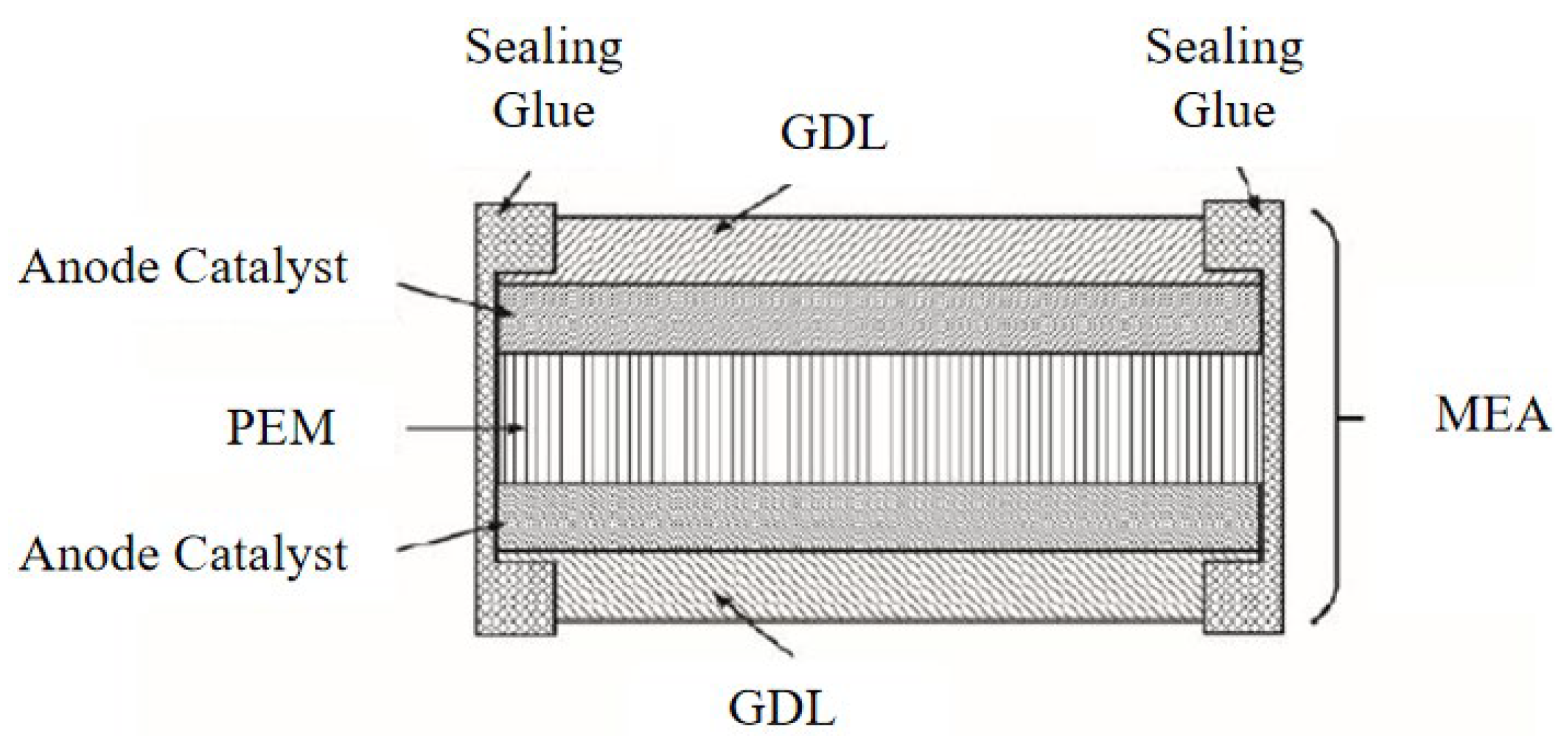
3.3. Seal Wrapped Proton Exchange Membrane Type Frame
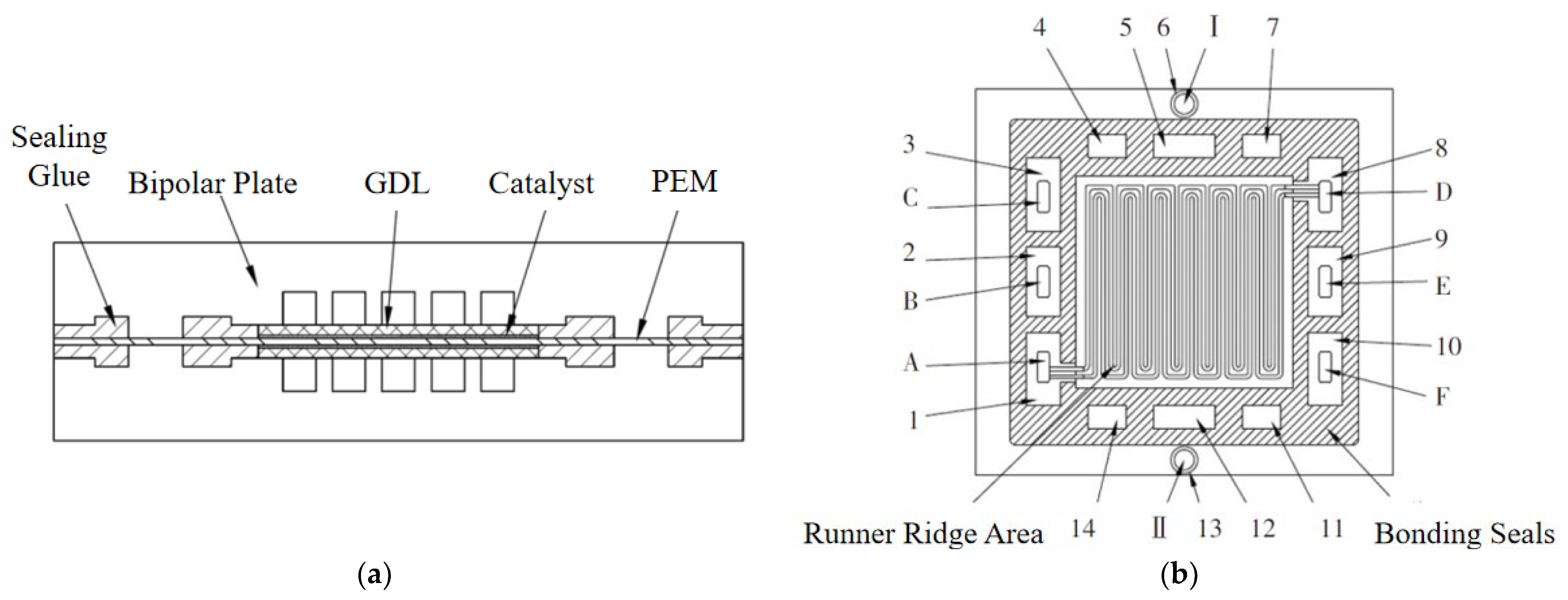
3.4. Seal-Wrapped Membrane Electrode-Type Frame
4. Factors Affecting the Sealing of the Battery in the Assembly Process
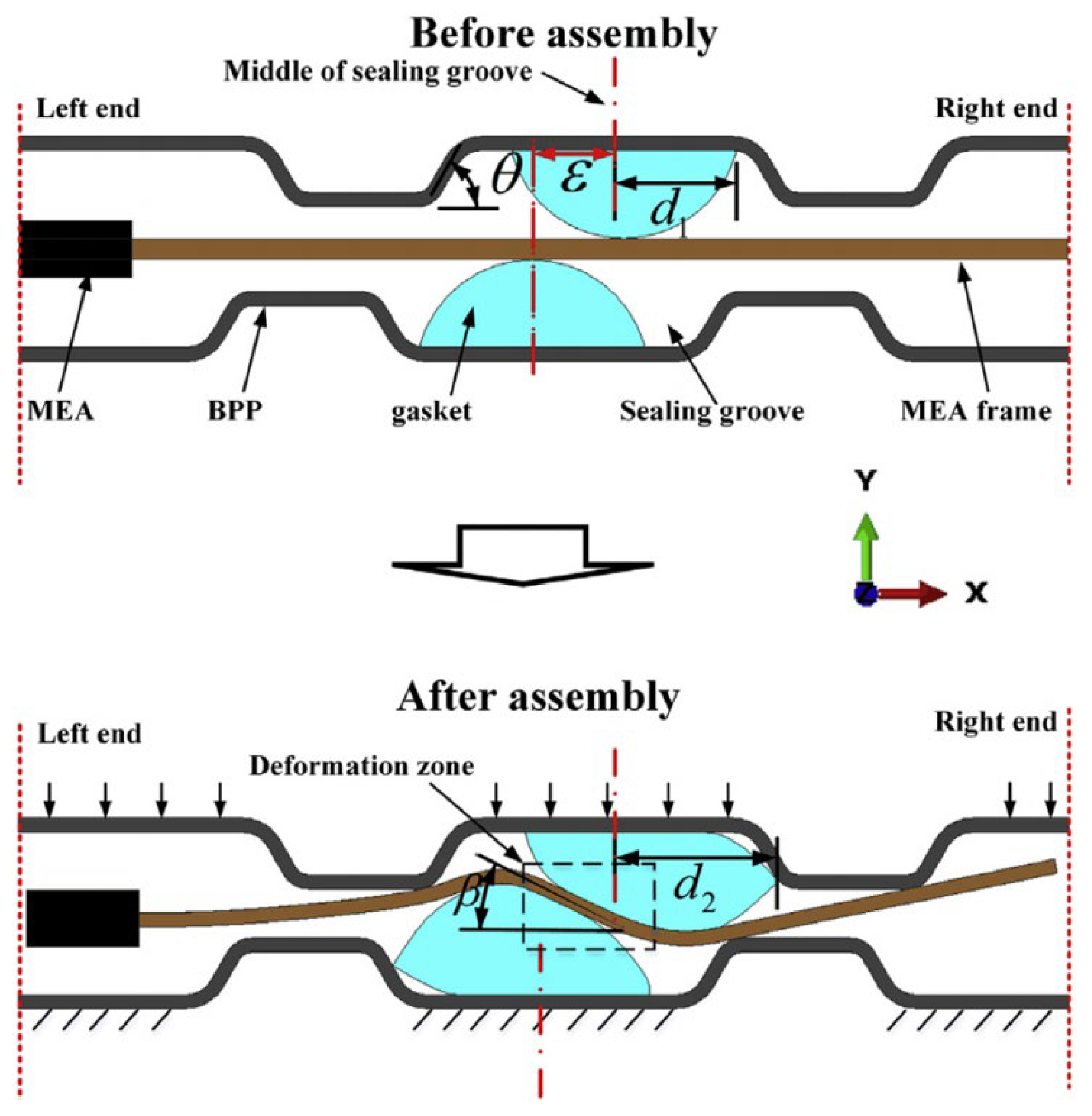
4.1. Assembly Error
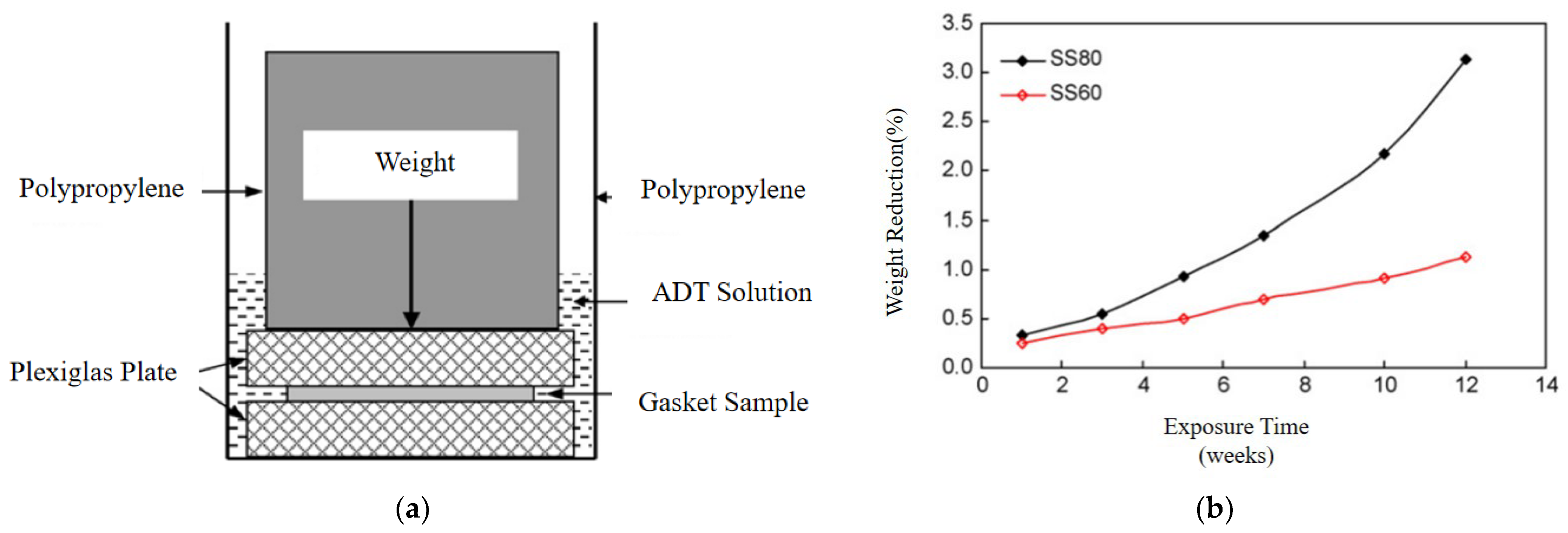
4.2. Gasket
4.3. Seal Leakage
5. Factors Affecting the Sealing of the Battery during Operation
5.1. Vibration
5.2. Circulating Temperature and Humidity
5.3. Cyclic Assembly
6. Conclusions
Author Contributions
Funding
Data Availability Statement
Acknowledgments
Conflicts of Interest
References
- Jia, Y.H.; Qi, Z.L.; You, H. Power production enhancement with polyaniline composite anode in benthic microbial fuel cells. J. Cent. South Univ. 2018, 25, 499–505. [Google Scholar] [CrossRef]
- Liu, G.; Liu, T.; Wei, Z.; Zhang, Q. Effects of different poses and wind speeds on flow field of dish solar concentrator based on virtual wind tunnel experiment with constant wind. J. Cent. South Univ. 2018, 25, 1948–1957. [Google Scholar] [CrossRef]
- Doe, U. Multiyear Research Development and Demonstration Plan: Planned Program Activities for 2011–2020; Office DFCT, US Department of Energy: Washngton, DC, USA, 2017; pp. 3–4. [Google Scholar]
- Arfeen, Z.A.; Abdullah, M.P.; Hassan, R.; Othman, B.M.; Siddique, A.; Rehman, A.U.; Sheikh, U.U. Energy storage usages: Engineering reactions, economic-technological values for electric vehicles—A technological outlook. Int. Trans. Electr. Energy Syst. 2020, 30, e12422. [Google Scholar] [CrossRef]
- Kim, A.R.; Vinothkannan, M.; Ramakrishnan, S.; Park, B.-H.; Han, M.-K.; Yoo, D.J. Enhanced electrochemical performance and long-term durability of composite membranes through a binary interface with sulfonated unzipped graphite nanofibers for polymer electrolyte fuel cells operating under low relative humidity. Appl. Surf. Sci. 2022, 593, 153407. [Google Scholar] [CrossRef]
- Meng, T.; Ciu, D.; Ji, Y.L. Optimization and efficiency analysis of methanol SOFC-PEMFC hybrid system. Int. J. Hydrogen Energy 2022, 47, 27690–27702. [Google Scholar] [CrossRef]
- Chen, R.R.; Luo, Q.; Luo, X.L. Design and operation optimization of an on-site hydrogen production and purification integration system for PEMFC. Fuel 2024, 370, 131834. [Google Scholar] [CrossRef]
- Li, X.; Wang, Y.D.; Zhan, M. Review on sealing materials for proton exchange membrane fuel cell. J. Ship Electr. Technol. 2020, 6, 19–23. [Google Scholar]
- Ye, D.H.; Zhan, Z.G. A review on the sealing structures of membrane electrode assembly of proton exchange membrane fuel cells. J. Power Sources 2013, 231, 285–292. [Google Scholar] [CrossRef]
- Qiu, D.; Peng, L.; Yi, P.; Lehnert, W.; Lai, X. Review on proton exchange membrane fuel cell stack assembly: Quality evaluation, assembly method, contact behavior and process design. Renew. Sustain. Energy Rev. 2021, 152, 111660. [Google Scholar] [CrossRef]
- Song, K.; Wang, Y.; Ding, Y.; Mueller-Welt, P.; Stuermlinger, T. Assembly techniques for proton exchange membrane fuel cell stack: A literature review. Renew. Sustain. Energy Rev. 2022, 153, 111777. [Google Scholar] [CrossRef]
- Tan, J.; Chao, Y.J.; Yang, M. Chemical and mechanical stability of a Silicone gasket material exposed to PEM fuel cell environment. Int. J. Hydrogen Energy 2011, 36, 1846–1852. [Google Scholar] [CrossRef]
- Lin, C.W.; Chen, C.H.; Tan, J. Dynamic mechanical characteristics of five elastomeric gasket materials aged in a simulated and an accelerated PEM fuel cell environment. Int. J. Hydrogen Energy 2011, 36, 6756–6767. [Google Scholar] [CrossRef]
- Xu, Y.; Li, X.B.; Zhou, Y.O. Persson’s theory of purely normal elastic rough surface contact: A tutorial based on stochastic process theory. Int. J. Solids Struct. 2024, 290, 112684. [Google Scholar] [CrossRef]
- Ma, B.; Jin, F.; Sun, Z. Leakage analysis of bolted flange joints considering surface roughness: A theoretical model. Proc. Inst. Mech. Eng. Part E J. Process Mech. Eng. 2017, 232, 203–233. [Google Scholar] [CrossRef]
- Lorenz, B.; Persson, B.N. Leak rate of seals: Effective-medium theory and comparison with experiment. Eur. Phys. J. E 2010, 31, 159–167. [Google Scholar] [CrossRef] [PubMed]
- Lorenz, B.; Persson, B.N. Leak rate of seals: Comparison of theory with experiment. Europhys. Lett. 2009, 86, 44006. [Google Scholar] [CrossRef]
- Kucaba-Pietal, A. Scale effect in microflows modelling with the micropolar fluid theory. In Proceedings of the Scale Effect in Microflows Modelling with the Micropolar Fluid Theory, Crete Island, Greece, 5–10 June 2016. [Google Scholar]
- Persson, B.N.J. Contact Mechanics for Randomly Rough Surfaces: On the Validity of the Method of Reduction of Dimensionality. Tribol. Lett. 2015, 58, 11. [Google Scholar] [CrossRef]
- Scaraggi, M.; Persson, B.N.J. General contact mechanics theory for randomly rough surfaces with application to rubber friction. J. Chem. Phys. 2015, 143, 224111. [Google Scholar] [CrossRef] [PubMed]
- Carral, C.; Mele, P. A numerical analysis of PEMFC stack assembly through a 3D finite element model. Int. J. Hydrogen Energy 2014, 39, 4516–4530. [Google Scholar] [CrossRef]
- Habibnia, M.; Shakeri, M.; Nourouzi, S. Determination of the effective parameters on the fuel cell efficiency, based on sealing behavior of the system. Int. J. Hydrogen Energy 2016, 41, 18147–18156. [Google Scholar] [CrossRef]
- Wei, C.; Wu, Z.; Jiang, D. Effect of temperature on output performance of proton exchange membrane fuel cell. J. Renew. Energy Resour. 2021, 39, 1588–1593. [Google Scholar]
- Shizuku, F.; Okada, S.; Kajiwara, T. Fuel Cell Resin Frame Assembly. U.S. Patent No. 10,522,851, 31 December 2019. [Google Scholar]
- Hübne, G. Membrane, Membrane-Electrode Assembly, Fuel Cell and Method for Prducing a Membrane. U.S. Patent No. 10,573,916, 25 February 2020. [Google Scholar]
- Yoshida, H.; Wachi, D. Fuel Cell with a Seal Tightly in Contact with an Electrode for Preventing Leakage of a Reactant Gas. U.S. Patent No. 7,326,485, 15 February 2008. [Google Scholar]
- Steinbach, A.J.L.; Debe, M.K. Gas Diffusion Layer Incorporating a Gasket. US Patent 7,732,083, 8 June 2010. [Google Scholar]
- Yuan, X.Z.; Shi, Z.Q.; Song, J.C. MEA—Membrane Electrode Assembly. Encycl. Energy Storage 2022, 276–289. [Google Scholar]
- Shi, D.C.; Cai, L.; Zhang, C.Z. Fabrication methods, structure design and durability analysis of advanced sealing materials in proton exchange membrane fuel cells. Chem. Eng. J. 2023, 454, 139995. [Google Scholar] [CrossRef]
- Zhang, S.H.; Wang, Z.H.; Zhang, R.L. Comprehensive study and optimization of membrane electrode assembly structural composition in proton exchange membrane water electrolyzer. Int. J. Hydrogen Energy 2023, 48, 35463. [Google Scholar] [CrossRef]
- Ishikawa, H.; Teramoto, T.; Ueyama, Y. Use of a Sub-Gasket and Soft Gas Diffusion Layer to Mitigate Mechanical Degradation of a Hydrocarbon Membrane for Polymer Electrolyte Fuel Cells in Wet-Dry Cycling. J. Power Sources 2016, 325, 35–41. [Google Scholar] [CrossRef]
- Jacobine, A.F.; Woods, J.G.; Nakos, S.T.; Burdzy, M.P.; Einsla, B.R.; Welch, K.J. UV-Curable Fuel Cell Sealants and Fuel Cells Formed Therefrom. US Patent 20090004541, 1 January 2009. [Google Scholar]
- Chen, M.; Liu, M.J.; Feng, Y. Technical challenges and enhancement strategies for transitioning PEMFCs from H2-air to H2-O2. Energy Convers. Manag. 2024, 311, 118525. [Google Scholar] [CrossRef]
- Yin, J.; Yang, F.; Yang, D. Design and simulation of integrated seal for proton exchange membrane fuel cell. J. Automob. Technol. 2021, 7, 15–21. [Google Scholar]
- Liang, P.; Qiu, D.K.; Peng, L.F. Structure failure of the sealing in the assembly process for proton exchange membrane fuel cells. Int. J. Hydrogen Energy 2017, 42, 10217–10227. [Google Scholar] [CrossRef]
- Kömmling, A. Comparison of different test methods for lifetime prediction of O-ring seals. In Proceedings of the Polymer Degradation Discussion Group Conference, St. Julian, Malta, 1–5 September 2019. [Google Scholar]
- Peng, L.; Liu, D.A.; Hu, P. Fabrication of metallic bipolar plates for proton exchange membrane fuel cell by flexible forming process-numerical simulations and experiments. J. Fuel Cell Sci. Technol. 2010, 7, 031009. [Google Scholar] [CrossRef]
- Peng, L.; Lai, X.; Yi, P. Design, optimization, and fabrication of slotted-interdigitated thin metallic bipolar plates for PEM fuel cells. J. Fuel Cell Sci. Technol. 2010, 8, 011002. [Google Scholar] [CrossRef]
- Choirotin, I.; Choiron, M.A. Defect Prediction at The Superplastic Forming Process of The Bipolar Plate by Simulation. J. Energy Mech. Mater. Manuf. Eng. 2018, 3, 49–54. [Google Scholar] [CrossRef]
- Xu, Y.; Peng, L.; Yi, P. Analysis of the flow distribution for thin stamped bipolar plates with tapered channel shape. Int. J. Hydrogen Energy 2016, 41, 5084–5095. [Google Scholar] [CrossRef]
- Tan, J.; Chao, Y.J.; Li, X. Degradation of silicone rubber under compression in a simulated. PEM Fuel Cell Environ. 2007, 172, 782–789. [Google Scholar]
- Li, G.; Gong, J.M.; Tan, J.Z. Stress relaxation behavior and life prediction of gasket materials used in proton exchange membrane fuel cells. J. Central South Univ. 2019, 26, 623–631. [Google Scholar] [CrossRef]
- Qiu, D.; Liang, P.; Peng, L.; Yi, P.; Lai, X.; Ni, J. Material behavior of rubber sealing for proton exchange membrane fuel cells. Int. J. Hydrogen Energy 2020, 45, 5465–5473. [Google Scholar] [CrossRef]
- Wu, F.; Chen, B.; Pan, M. Degradation of the sealing silicone rubbers in a proton exchange membrane fuel cell at cold start conditions. Int. J. Electrochem. Sci. 2020, 15, 3013–3028. [Google Scholar] [CrossRef]
- Chang, H.; Wan, Z.; Chen, X. Temperature and humidity effect on aging of silicone rubbers as sealing materials for proton exchange membrane fuel cell applications. Appl. Therm. Eng. 2016, 104, 472–478. [Google Scholar] [CrossRef]
- Xia, L.; Wang, M.; Wu, H. Effects of cure system and filler on chemical aging behavior of fluoroelastomer in simulated proton exchange membrane fuel cell environment. Int. J. Hydrogen Energy 2016, 41, 2887–2895. [Google Scholar] [CrossRef]
- Cleghorn, S.J.C.; Mayfield, D.K.; Moore, D.A. A polymer electrolyte fuel cell life test: 3 years of continuous operation. J. Power Sources 2006, 158, 446–454. [Google Scholar] [CrossRef]
- Yang, Z.; Zhu, W.F.; Dong, R. Multi-scale dimensionless prediction model of PEMFC sealing interface leakage rate based on fractal geometry. Int. J. Hydrogen Energy 2023, 48, 5276–5287. [Google Scholar] [CrossRef]
- Yang, Z.; Zhu, W.F.; Zhang, Q.Q. PEMFC sealing modeling relating to fractal characteristics of gasket-BPP interface based on micro-contact. Int. J. Hydrogen Energy 2024, 63, 803–814. [Google Scholar] [CrossRef]
- Yang, C.; Persson, B.N.J. Contact mechanics: Contact area and interfacial separation from small contact to full contact. J. Phys. Condens. Matter 2008, 20, 13. [Google Scholar] [CrossRef]
- Aweimer, A.S.O.; Bouzid, A.H. Evaluation of interfacial and permeation leaks in gaskets and compression packing. J. Nucl. Eng. Radiat. Sci. 2019, 5, 9. [Google Scholar] [CrossRef]
- Husar, A.; Serra, M.; Kunusch, C. Description of gasket failure in a 7 cell PEMFC stack. J. Power Sources 2007, 169, 85–91. [Google Scholar] [CrossRef]
- Chen, C.Y.; Su, S.C. Effects of assembly torque on a proton exchange membrane fuel cell with stamped metallic bipolar plates. Energy 2018, 159, 440–447. [Google Scholar] [CrossRef]
- ASTM D3078-02(2021)e1; Standard Test Method for Determination of Leaks in Flexible Packaging by Bubble Emission. ASTM International: West Conshohocken, PA, USA, 2021.
- Xu, Q.; Zhao, J.; Chen, Y. Effects of gas permeation on the sealing performance of PEMFC stacks. Int. J. Hydrogen Energy 2021, 46, 36424–36435. [Google Scholar] [CrossRef]
- Qiu, D.K.; Peng, L.; Lai, X. Mechanical failure and mitigation strategies for the membrane in a proton exchange membrane fuel cell. Renew. Sustain. Energy Rev. 2019, 113, 109289. [Google Scholar] [CrossRef]
- Hou, Y.; Zhou, W.; Shen, C. Experimental investigation of gas-tightness and electrical insulation of fuel cell stack under strengthened road vibrating conditions. Int. J. Hydrogen Energy 2011, 36, 13763–13768. [Google Scholar] [CrossRef]
- Deshpande, J.; Dey, T.; Ghosh, P.C. Effect of vibrations on performance of polymer electrolyte membrane fuel cells. Energy Procedia 2014, 54, 756–762. [Google Scholar] [CrossRef]
- Rajalakshmi, N.; Pandian, S.; Dathathreyan, K.S. Vibration Tests on a PEM Fuel Cell Stack Usable in Transport Application. Int. J. Hydrogen Energy 2009, 34, 3383–3387. [Google Scholar]
- Cui, T.; Chao, Y.; Van Zee, J. Sealing force prediction of elastomeric seal material for PEM fuel cell under temperature cycling. Int. J. Hydrogen Energy 2014, 39, 1430–1438. [Google Scholar] [CrossRef]
- Kim, T.; Nguyen, N.D.; Kim, Y.; Yu, S. Experimental investigation of time-dependent electrical load effects through multipoints in-situ measurement of temperature and relative humidity of PEMFC bipolar plate under transient operation. Appl. Therm. Eng. 2024, 247, 123049. [Google Scholar] [CrossRef]
- Zhang, J.; Hu, Y. Sealing performance and mechanical behavior of PEMFCs sealing system based on thermodynamic coupling. Int. J. Hydrogen Energy 2020, 45, 23480–23489. [Google Scholar] [CrossRef]
- Zhang, N.; Li, Q.; Hu, K. Compressive and Sealing Characteristics of PTFE under Cyclic Loading-unloading. J. Wuhan Univ. Technol. Mater. Sci. Ed. 2015, 30, 181–184. [Google Scholar] [CrossRef]
- Pei, H.C.; Xing, L.; Chen, J.B. Visualisation study on water management of cathode dead-ended PEMFC under pressure-swing operation. Prog. Nat. Sci. Mater. Int. 2024; in press. [Google Scholar] [CrossRef]


Disclaimer/Publisher’s Note: The statements, opinions and data contained in all publications are solely those of the individual author(s) and contributor(s) and not of MDPI and/or the editor(s). MDPI and/or the editor(s) disclaim responsibility for any injury to people or property resulting from any ideas, methods, instructions or products referred to in the content. |
© 2024 by the authors. Licensee MDPI, Basel, Switzerland. This article is an open access article distributed under the terms and conditions of the Creative Commons Attribution (CC BY) license (https://creativecommons.org/licenses/by/4.0/).
Share and Cite
Wei, Y.; Xing, Y.; Zhang, X.; Wang, Y.; Cao, J.; Yang, F. A Review of Sealing Systems for Proton Exchange Membrane Fuel Cells. World Electr. Veh. J. 2024, 15, 358. https://doi.org/10.3390/wevj15080358
Wei Y, Xing Y, Zhang X, Wang Y, Cao J, Yang F. A Review of Sealing Systems for Proton Exchange Membrane Fuel Cells. World Electric Vehicle Journal. 2024; 15(8):358. https://doi.org/10.3390/wevj15080358
Chicago/Turabian StyleWei, Yi, Yanfeng Xing, Xiaobing Zhang, Ying Wang, Juyong Cao, and Fuyong Yang. 2024. "A Review of Sealing Systems for Proton Exchange Membrane Fuel Cells" World Electric Vehicle Journal 15, no. 8: 358. https://doi.org/10.3390/wevj15080358
APA StyleWei, Y., Xing, Y., Zhang, X., Wang, Y., Cao, J., & Yang, F. (2024). A Review of Sealing Systems for Proton Exchange Membrane Fuel Cells. World Electric Vehicle Journal, 15(8), 358. https://doi.org/10.3390/wevj15080358