Abstract
Land vehicle gravity anomaly measurement relies heavily on global navigation satellite system (GNSS). However, when gravity measurement is carried out in special environments such as forests, valleys and tunnels, GNSS observation quality will inevitably decline, which directly affects the accuracy of gravity anomaly measurement. From the point of view of the gravity anomaly measurement principle, obtaining accurate elevation information of the test line is the premise to ensure the accuracy of gravity anomaly measurement. Thus, this paper proposes a strapdown land vehicle dynamic gravity anomaly measurement method combining an odometer and a geo-information system. In this method, strapdown inertial navigation errors are suppressed by observing the velocity of the odometer output. Then, the position information obtained by the combined navigation is entered into the geo-information system to obtain the elevation. The results of a single test line show that the external coincidence accuracy of the proposed method is 1.65 mGal, and the accuracy is comparable to the traditional GNSS assisted land vehicle gravimetry method. In addition, compared with the odometer assisted land vehicle gravimetry method, the external coincidence accuracy is increased by 30%.
1. Introduction
The gravity field is a fundamental physical property of the Earth, reflecting the distribution and variation of materials within it [1]. According to the different physical quantities measured, the methods of measuring the Earth’s gravity field can be divided into absolute gravity measurement and relative gravity measurement. Absolute gravity measurement directly measures the value of gravity at a single point on the ground. Relative gravity measurement measures the gravity difference between two test points and indirectly obtains the gravity value of each test point. Modern absolute gravity measuring instruments are complex precision instruments based on laser technology or atomic interference technology, and the measurement accuracy can reach μGal level [2,3]. However, the adaptability of the absolute gravity measuring instrument to the field environment is not good, and it is relatively complex to realize the gravity measurement of the moving base [4,5,6]. Gravimeters made using the principle of pressure balance or force balance fall into the category of relative gravity measurement [7,8]. At present, the instruments used for relative gravity measurement all adopt the principle of force balance, and the core components are quartz springs or metal wires [9].
To improve the efficiency of gravity measurement, many scholars have studied the gravity measurement methods of the dynamic base carried out by relative gravimeters on underwater robots, ships, hot air balloons, drones, and other carriers [10,11,12,13]. According to different carriers, gravity measurement of the dynamic base can be divided into ship, underwater, airborne, and land vehicle gravity measurements. Among them, the primary use of airborne and land vehicle gravity surveys is the rapid measurement of the ground gravity field. Airborne gravity measurement is highly efficient and can be completed in complex areas such as deserts, glaciers, and forests. However, the airborne gravity measurement method measures the gravity information of the aircraft’s flight path, which often needs to be extended downward [14]. Compared with airborne gravimetry, land vehicle gravimetry can obtain gravity information with a high signal-to-noise ratio and good accuracy without complicated data extension. Land vehicle gravimetry has been widely used in geoid determination, groundwater resource surveying, underground cavity detection, gravity assisted navigation, and other fields [15,16].
For a long time, global satellite navigation systems (GNSS) have played a vital role in dynamic gravity measurement activities [17,18,19,20,21,22,23]. First, observing GNSS position and velocity information can suppress the errors of a strapdown inertial navigation system (SINS) [24]. Second, GNSS positioning information is neededs to solve the carrier acceleration problem [25]. Lastly, GNSS information can be used to calculate the Eotvos correction and normal gravity.
However, vehicles performing gravimetric activities on the ground inevitably encounter complex GNSS observation environments, such as tall urban buildings, tunnels, overpasses, and dense forests. This leads to a decline in the observation quality of GNSS, which directly affects the accuracy of gravity measurement [26]. To eliminate the dependence of land vehicle gravimetry activities on GNSS positioning information, a SINS/velocimeter (VEL) land vehicle gravimetry method was proposed in the literature [27]. This method obtains the carrier acceleration by differentiating the velocity information output by VEL. However, the elevation information of this method is obtained from the integrated navigation, which limits the accuracy of gravity measurement. The literature [28] proposed a land vehicle gravimetry method based on SINS/laser doppler velocimeter (LDV), which uses LDV to output the carrier’s elevation information to further improve gravity measurement accuracy. However, when the carrier travels slowly or encounters severe road turbulence, the optical velocimeter may fail to measure the velocity [29]. The resolution of the measurement results and the experiment’s reliability face severe challenges.
Aiming at the problems of the above methods, this paper proposes a land vehicle gravity anomaly measurement method combining an odometer (OD), geo-information system (GIS), and laser strapdown inertial navigation system. The aim is to free land vehicle gravimetric activities from their heavy reliance on GNSS information, enabling them to maintain the accuracy of gravimetry measurements in extreme environments. The proposed method provides an effective scheme for resource exploration and vehicle gravity assisted navigation.
This paper is organized as follows: Section 2 shows the mathematical model and error equation of strapdown land vehicle gravity anomaly measurement. Section 3 introduces the data processing flow of the SINS/OD/GIS gravity anomaly measurement method. Section 4 describes in detail the comparison test between the gravity anomaly measurement system and the land vehicle gravity measurement. Section 5 compares the accuracy of gravity anomaly measurement of the three methods. See Section 6 for conclusions.
2. Strapdown Land Vehicle Gravity Anomaly Measurement Principle
The reference coordinate systems commonly used in strapdown land vehicle gravimetry are the inertial coordinate system (-frame), the Earth coordinate system (-frame), the navigation coordinate system (-frame), the actual navigation coordinate system (-frame), the odometer coordinate system (-frame), and the body coordinate system (-frame). In this paper, the local geography coordinate system (E-N-U) is chosen as the navigation coordinate system.
2.1. Mathematical Model
The expression of gravity measurement can be obtained from the inertial navigation specific force equation:
where is the gravity, is the acceleration of the vehicle, is the direction cosine matrix from -frame to -frame, is the specific force output of the accelerometer, is the projection of the Earth’s rotational angular velocity in the -frame, is the projection of the angular velocity of the vehicle relative to Earth in the -frame, is the velocity of the carrier, and stands for transforming the vector into a skew symmetric matrix.
The detailed expressions of , , , and are as follows:
where , and are eastward gravity, north gravity and upward gravity respectively, and stand for calculating values of sine and cosine, is the rolling angle of vehicle, is the yaw angle of the vehicle, is the pitch angle of the vehicle, is the upward component of the Earth’s rotational angular velocity. is the latitude, and are the curvature radii of the prime upward and meridian, is the elevation of the vehicle, and , and are the land vehicle’s north velocity, eastward velocity and upward velocity respectively.
Gravity is considered to be the sum of the normal gravity ( denote the upward component of the normal gravity) and the gravity disturbance [30]:
The upward component of the normal gravity can be directly calculated using the following equations:
So, measuring gravity is equivalent to measuring gravity disturbance. The expression of gravity disturbance can be obtained by combining Equations (1) and (2) [31]:
In -frame, gravity disturbance can be decomposed into north component of gravity disturbance, east component of gravity disturbance and gravity anomaly. This paper mainly studies the measurement of gravity anomaly. The other two components are measured in the same way, and the accuracy is closely related to the precision of the gyroscope in SINS.
By expanding Equation (3) in the -frame, the expression of gravity anomaly is as follows:
where is the upward component of the gravity disturbance, is the upward component of the vehicle’s velocity, and is the upward component of the specific force.
In geodesy and navigation, the Eotvos correction is denoted as .
Therefore, Equation (4) can be further expressed as:
The relationship of gravity, normal gravity and gravity disturbance is shown in Figure 1. and are the meridian component and prime unitary component.
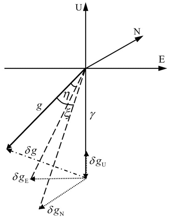
Figure 1.
Relationship of gravity, normal gravity and gravity disturbance at a certain point in local navigation coordinate system.
2.2. Error Model
Applying the variational operation to Equation (3), the error model of gravity anomaly measurement is obtained:
where is the measurement error of gravity anomaly, is the vehicle’s acceleration measurement error, is the projection of the specific force on the -frame, is the specific force measurement error, is the attitude error, is the Earth rotation angular velocity calculation error, is the calculation error of the vehicle relative to the earth angular velocity, is the vehicle’s velocity error, and is the normal gravity calculation error.
Expand Equation (5) into component form:
where , , and are the measurement errors of eastward gravity disturbance, north gravity disturbance and gravity anomaly, respectively, and , , and are the errors of land vehicle’s eastward acceleration, north acceleration, and upward acceleration respectively. and are the eastward specific force and north specific force, , , and are the eastward specific force measurement error, north specific force measurement error, and upward specific force measurement error, respectively, , , and are the eastward attitude error, north attitude error, and upward attitude error, respectively, , , and are the measurement error of eastward velocity, north velocity and upward velocity, respectively, is the latitude error, and is the upward normal gravity calculation error.
The upward component of Equation (6) is the measurement error model of gravity anomaly:
The influence of latitude on gravity anomaly measurement accuracy is denoted as , which can be obtained from Equation (7):
It is assumed that in a land vehicle gravity measurement test, the east velocity of the vehicle is 10 m/s, and the maximum latitude positioning error is 100 m. As seen from Equation (8), the gravity anomaly measurement error caused by the latitude positioning error in this test is no more than 0.1 mGal.
In this paper, the upward gravity gradient of the Earth is taken as 0.3 mGal/m. So, can be further expressed as:
where is the error of elevation.
According to Equation (9), an elevation error of only 3.3 m will cause a gravity anomaly measurement error of 1 mGal.
Similarly, the influences of IMU error, velocity error and acceleration error on gravity anomaly measurement are respectively denoted as , , and . As can be seen from Equation (7):
So, Equation (7) can be abbreviated as:
In summary, the measurement accuracy of the land vehicle gravity anomaly is related to the measurement accuracy of carrier acceleration, IMU, latitude positioning, velocity measurement and elevation measurement. The latitude positioning accuracy has little effect on the gravity anomaly measurement accuracy. The accuracy of elevation has great influence on the accuracy of the gravity anomaly measurement.
3. SINS/OD/GIS Gravity Anomaly Measurement Method
As previously discussed, high-precision positioning, attitude error correction, and elevation information have significant positive implications for enhancing the accuracy of land vehicle gravity measurements. Firstly, the latitude, east velocity, and north velocity obtained by integrated navigation are essential information for gravity signal extraction. Secondly, the strapdown land vehicle gravity measurement adopts the mathematical model under the local navigation coordinate system. However, since SINS is firmly connected to the carrier, the output is a specific force of -frame. Gravity measurement can only be carried out after further calculating the direction cosine matrix to obtain the upward specific force . This paper uses an error-state Kalman filter to fuse SINS and OD information. The odometer’s velocity output suppresses SINS errors, improving the accuracy of latitude positioning, combined navigation velocity, and specific force measurement.
In addition, the gravity disturbance information directly extracted by Equation (4) contains high-frequency noise, which a suitable filter must filter before the gravity anomaly can be obtained.
So, gravity anomaly measurement can be regarded as a combination of navigation and gravity extraction.
The specific flow is summarized as follows:
- (1)
- SINS performs an inertial navigation solution, and the velocity of OD is observed for integrated navigation. The carrier’s specific force, attitude, velocity, and position information are calculated using SINS/OD integrated navigation.
It should be noted that the original OD data can be used for integrated navigation only after being converted to the -frame using the direction cosine matrices and in turn. The conversion equation for the odometer velocity is as follows:
where is the projection of the odometer velocity in the -frame, and is the direction cosine matrix from -frame to -frame.
In real conditions, SINS has an installation error angle, and the calibration coefficient of the odometer is also affected by tire wear and tire pressure changes. Combined with Equation (11), the actual output of the odometer can be obtained after ignoring a small amount:
where is the odometer taking into account the actual output of the -frame after various errors, is the unit matrix, is the misalignment angle between the -frame and the -frame, is the misalignment angle between the -frame and the -frame, and are SINS installation error angles, and is the odometer calibration coefficient error.
SINS/OD integrated navigation selects an 18-dimensional error state vector:
where is the status vector of the SINS/OD integrated navigation system, is the projection of onto the -frame, is the projection of velocity error in -frame, is the projection of position error in -frame, is the gyro zero drift, is the constant zero bias of the specific force sensor, and is the augmented error vector, which can be treated as random constant states, that is,
Differential equations for navigation error state vectors in Equation (13) are as follows:
The differential equation of IMU error state vectors in Equation (13) are as follows:
Combining differential equations of error state vectors, we can obtain the 18-dimensional augmented state equations of Kalman filter as follows:
where is the state error, is the state transition matrix, is the noise-driven matrix, and is the process noise.
With the OD output velocity as the true value, the SINS output velocity can be expressed as:
where is the actual output velocity of SINS, and is the OD indicating the actual output velocity.
Further, by combining the Equations (12) and (15), we can obtain:
The difference between the output velocity of SINS and that of the odometer is taken as a measurement, and the measurement equation of the system is as follows:
where is the observation vector, is the coefficient matrix of the observed vector, and is the equivalent matrix of . The specific expression of is as follows:
where means that all the elements in column of are taken out to form a new number table.
Combining Equations (14) and (17), we can obtain the 18-dimensional error state equations of Kalman filter as follows:
- (2)
- The commercial geographic information software ArcGIS 10.8 was used to extract the elevation information of the survey line. See Figure 2 for the specific process.
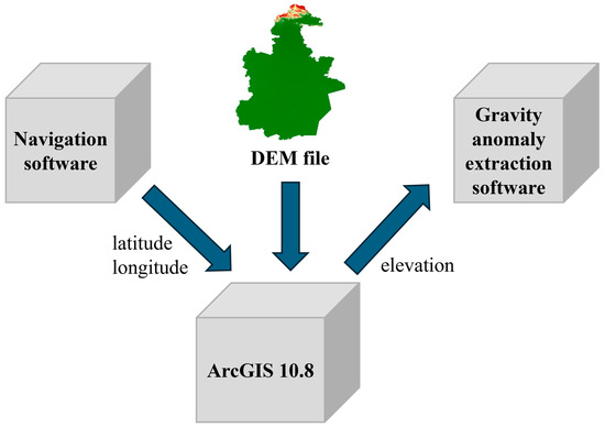 Figure 2. The process of elevation extraction by ArcGIS 10.8.
First, the longitude and latitude data of SINS/OD integrated navigation are stored. Then, the latitude and longitude data are input into ArcGIS 10.8, and the DEM data of the city where the survey line is located is selected. Second, the elevation information output by ArcGIS is stored in an Excel file. Lastly, the line elevation information stored in Excel is input into the gravity anomaly extraction software.
The accuracy of the elevation information obtained by this method is related to the accuracy of the DEM file.
- (3)
- The original gravity anomaly is calculated by Equation (4).
Figure 3 illustrates the functions of various sensors in the measurement of gravity anomaly information. OD provides velocity information and is used to calculate the kinematic acceleration of the vehicle. After solving SINS and OD integrated navigation, the high-precision attitude and specific force can be output for upward specific force calculation. The , , , , , , and output by SINS/OD integrated navigation are used to calculate the Eotvos correction. The normal gravity is calculated by using the elevation output of ArcGIS 10.8 and , , and of the SINS/OD integrated navigation solution.
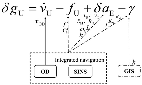
Figure 3.
The functions of various sensors in the measurement of gravity anomaly.
Further, the original gravity anomaly information containing high-frequency noise is filtered by using an FIR filter to obtain the gravity anomaly information.
- (4)
- The external coincidence accuracy evaluation is carried out.
This paper uses gravity anomalies calculated by the EGM2190 model as reference values, and REF represents the data.
The calculation formula for the accuracy evaluation of test line data is as follows:
where is the external coincidence accuracy of land vehicle gravity measurement, is the measured gravity anomalies at point , is the gravity values calculated by the EGM2190 model at point , and is the measure the total number of sampling points on the test line.
Figure 4 is the data processing flow chart of the SINS/OD/GIS gravity measurement method.
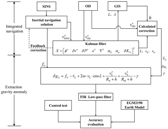
Figure 4.
Data processing flow of the SINS/OD/GIS method.
4. Experiments
In March 2024, the research group carried out a land vehicle dynamic gravity measurement test on a highway in Tianjin. This experiment aimed to verify the accuracy of the proposed method and the reliability of the gravity measurement system. The method proposed in this paper was used as the experimental group; the traditional SINS/GNSS method and SINS/OD method were used as the control tests. The specific process of these two methods can be seen in reference [32].
We equipped an SUV with a self-developed dual-axis rotating laser strapdown inertial navigation system, odometer, GNSS positioning equipment, and other necessary equipment. The role of GNSS is to provide a positioning benchmark. The navigation computer, battery, odometer, and strapdown inertial navigation system constitute the land vehicle gravity anomaly measurement system shown in Figure 5. Table 1 shows the detailed parameters of the above sensors.
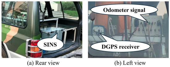
Figure 5.
Land vehicle gravity anomaly measurement system.

Table 1.
Sensor parameter.
Figure 6 shows the track of the gravity survey area. The blue line represents the path of the dynamic gravity measurement experiment. In this paper, the relative coordinates are used to represent the latitude of the X-axis and the longitude of the Y-axis. The driver steered the vehicle to run smoothly, the velocity was maintained at 19.6 km/h, and the vehicle did not undergo significant acceleration or deceleration maneuvers. In addition, the GNSS observation signal of the whole gravity sampling section was good.
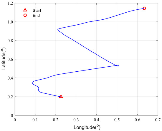
Figure 6.
Track of the gravity survey area.
5. Results and Discussion
5.1. Data Processing
To evaluate whether the positioning accuracy of SINS/OD integrated navigation meets the requirements of gravity measurement, the positioning results of SINS/GNSS integrated navigation are used as reference values to verify the degree of agreement between the positioning results of SINS/OD and the reference values. The results of SINS/OD integrated navigation are shown in Figure 7 and Figure 8.
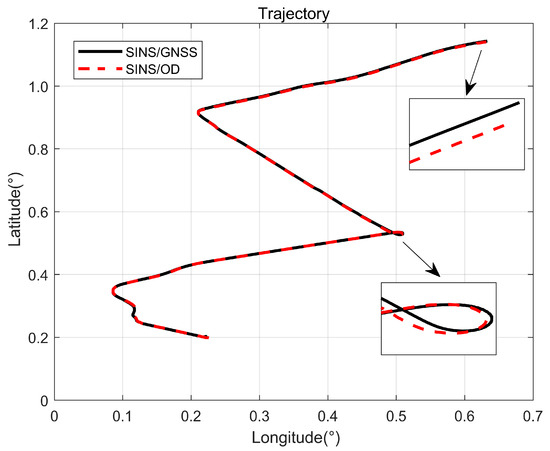
Figure 7.
Position plot of SINS/OD computation compared with the reference data.
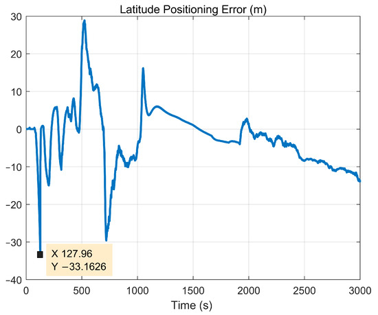
Figure 8.
Latitude error plot of SINS/OD computation compared with the reference data.
Figure 7 reflects the consistency of the positioning results of SINS/OD integrated navigation and SINS/GNSS integrated navigation. In addition, as can be seen from Figure 8, the latitude error of SINS/OD integrated navigation is less than 33.3 m. According to Equation (8), the gravity measurement error caused by the latitude positioning error of SINS/OD combined navigation can be ignored.
In fact, the elevation accuracy of GIS is not only related to the accuracy of the DEM file, but also to the horizontal positioning accuracy of SINS/OD integrated navigation. Considering that the horizontal positioning error of SINS/OD integrated navigation will directly affect the elevation accuracy, in this paper, only the data between 1280 s and 1920 s of the test are selected for gravity extraction. During this period, the horizontal positioning error of integrated navigation is small, and the elevation accuracy of GIS output is high.
Figure 9 shows the elevation error of GIS, taking the elevation output of SINS/GNSS integrated navigation as the reference value.
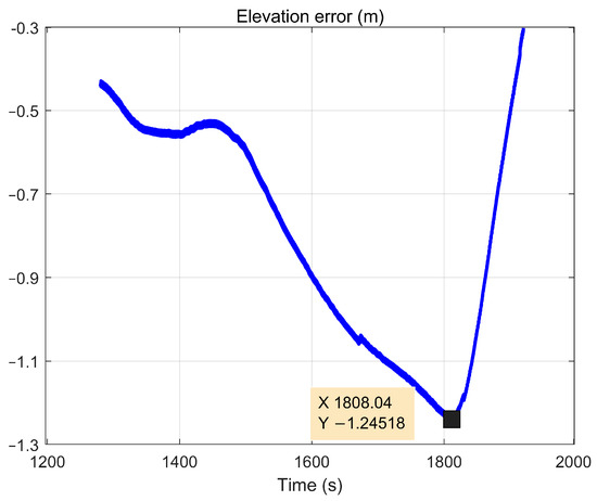
Figure 9.
Elevation error.
As Figure 9 shows, the maximum error of the GIS output elevation is better than 1.25 m, which meets the requirements of gravity measurement for elevation accuracy.
5.2. Test Results
Using the 100s FIR low-pass filtering result as an example, Figure 10 shows the gravity anomaly results of the three methods in this test.
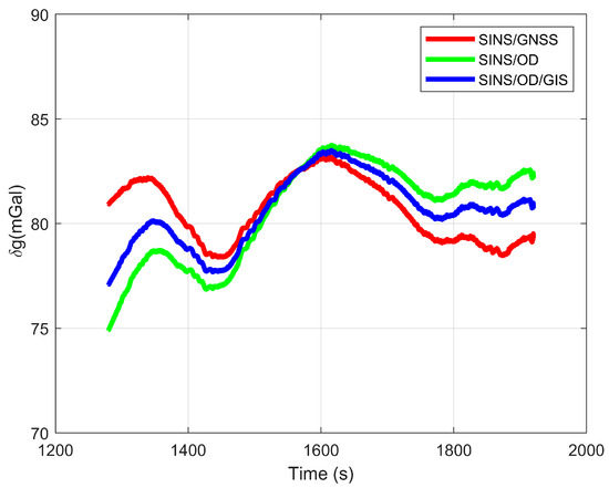
Figure 10.
Comparisons of filtered gravity anomaly.
To improve the efficiency of gravity measurement, the gravity reference point was not established by ground-static gravity measurement. Instead, the gravity anomaly calculated by the EGM2190 model is used as a reference value to evaluate the accuracy of external coincidence.
Table 2 shows the statistical results of external coincidence accuracy. The proposed method has the same accuracy compared to the traditional SINS/GNSS method. Compared with the SINS/OD method, the outer coincidence accuracy of the proposed method is improved from 2.35 mGal to 1.65 mGal, which is a 30% increase in accuracy.
Table 2.
Gravity anomaly measurement external coincidence results (unit: mGal).
5.3. Discussion
The test results demonstrate that the proposed method achieves higher accuracy in gravity anomaly measurement compared to the SINS/OD method. The primary difference between the two methods lies in the calculation of normal gravity. Specifically, the SINS/OD method computes normal gravity using the elevation, latitude, curvature radius of the prime vertical circle, and curvature radius of the meridian circle derived from integrated navigation. In contrast, the SINS/OD/GIS method utilizes the elevation obtained from the GIS, along with other information provided by the SINS/OD integrated navigation to calculate normal gravity. To further elucidate the relationship between the gravity anomaly measurement performance and the elevation of the proposed method, we analyzed the elevation error of all three methods along the measurement line. The results are presented in Figure 11.
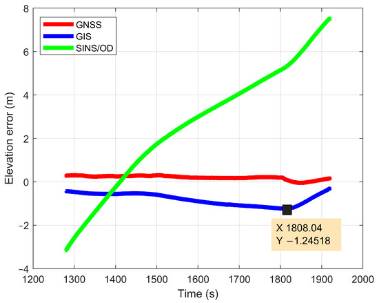
Figure 11.
Elevation error comparison of the three methods.
As depicted in Figure 11, the elevation error of the GNSS is very small. In contrast, the elevation error of the SINS/OD integrated navigation system exhibits divergence. The elevation error of the GIS, however, does not diverge over time, with a maximum elevation error of 1.24 m. According to Equation (9), in the SINS/OD/GIS method, the measurement error attributable to elevation is no more than 0.38 mGal. These findings indicate that the precision of gravity measurements can be significantly enhanced by utilizing the high-precision, non-divergent elevation information provided by GIS.
6. Conclusions
It is difficult to maintain the accuracy of gravity anomaly measurement in extreme environments when GNSS is used to assist the land vehicle dynamic gravity anomaly measurement. To solve this problem, a new method combining an odometer and digital map is proposed. From the dynamic test results, the external coincidence accuracy of the proposed method is better than 2 mGal, and the accuracy is comparable to the SINS/GNSS method. The elevation information obtained by GIS does not diverge with time and vehicle mileage, but the accuracy is limited. Further research should continue to focus on how to achieve autonomous and accurate elevation measurement, to ensure the measurement accuracy of gravity anomaly information. This paper can provide technical support for high-precision positioning of electric land vehicles and resource exploration.
Author Contributions
Conceptualization, J.Z. and Z.Z.; Methodology, K.Z.; Software, K.Z.; Writing—original draft preparation, K.Z.; Writing—review and editing, J.Z. and K.Z.; Funding acquisition Z.Z. and J.Z. All authors have read and agreed to the published version of the manuscript.
Funding
This work was supported in part by the National Natural Science Foundation of China (Grant No. 62305393) and the National Key Basic Research Strengthen Foundation of China (Grant No. 2021-JCJQ-JJ-0871).
Data Availability Statement
The data presented in this study are available on request from the corresponding author. The data are not publicly available due to confidentiality.
Conflicts of Interest
The authors declare no conflict of interest.
References
- Pistorio, A.; Greco, F.; Currenti, G.; Napoli, R.; Sicali, A.; Del Negro, C.; Fortuna, L. High-Precision Gravity Measurements Using Absolute and Relative Gravimeters at Mount Etna (Sicily, Italy). Ann. Geophys. 2011, 54, 5348. [Google Scholar] [CrossRef]
- Wang, H.; Wang, K.; Xu, Y.; Tang, Y.; Wu, B.; Cheng, B.; Wu, L.; Zhou, Y.; Weng, K.; Zhu, D.; et al. A Truck-Borne System Based on Cold Atom Gravimeter for Measuring the Absolute Gravity in the Field. Sensors 2022, 22, 6172. [Google Scholar] [CrossRef]
- Wu, B.; Li, D.; Zhou, Y.; Zhu, D.; Zhao, Y.; Qiao, Z.; Cheng, B.; Niu, J.; Guo, X.; Wang, X.; et al. Construction of a Test Field for Relative Gravimeters in a Cave With a Cold Atom Gravimeter. IEEE Sens. J. 2024, 24, 9536–9544. [Google Scholar] [CrossRef]
- Zhang, X.; Yan, S.; Li, Q.; Zhu, L.; Yang, J. Mobile gravity surveys in the field based on vehicle-mounted atom interferometer. Chin. J. Sci. Instrum. 2023, 44, 96–103. [Google Scholar] [CrossRef]
- Bidel, Y.; Zahzam, N.; Blanchard, C.; Bonnin, A.; Cadoret, M.; Bresson, A.; Rouxel, D.; Lequentrec-Lalancette, M.F. Absolute Marine Gravimetry with Matter-Wave Interferometry. Nat. Commun. 2018, 9, 627. [Google Scholar] [CrossRef]
- Bidel, Y.; Zahzam, N.; Bresson, A.; Blanchard, C.; Cadoret, M.; Olesen, A.V.; Forsberg, R. Absolute Airborne Gravimetry with a Cold Atom Sensor. J. Geod. 2020, 94, 20. [Google Scholar] [CrossRef]
- Ning, J.S.; Huang, M.T.; Ouyang, Y.Z.; Deng, K.L. Development of Marine and Airborne Gravity Measurement Technologies. Hydrogr. Surv. Charting 2014, 34, 67–72+76. [Google Scholar]
- Hu, P.H.; Zhao, M.; Huang, H.; Liu, D.B.; Tang, J.H.; Wei, C. Review on the Development of Airborne/Mairne Gravimetry Instruments. Navig. Position. Timing 2017, 4, 10–19. [Google Scholar] [CrossRef]
- Xiu, R.; Guo, G.; Xue, Z.B.; Li, D.M.; Li, H.B. Technical Current Situation and New Application of Marine/aviation Gravimeter. Navig. Control. 2019, 18, 35–43. [Google Scholar]
- Jekeli, C. Balloon Gravimetry Using GPS and INS. IEEE Aerosp. Electron. Syst. Mag. 1992, 7, 9–15. [Google Scholar] [CrossRef]
- Zhang, Z.; Li, J.; Zhang, K.; Yu, R. Experimental Study on Underwater Moving Gravity Measurement by Using Strapdown Gravimeter Based on AUV Platform. Mar. Geod. 2021, 44, 108–135. [Google Scholar] [CrossRef]
- Luo, K.; Cao, J.; Wang, C.; Cai, S.; Yu, R.; Wu, M.; Yang, B.; Xiang, W. First Unmanned Aerial Vehicle Airborne Gravimetry Based on the CH-4 UAV in China. J. Appl. Geophys. 2022, 206, 104835. [Google Scholar] [CrossRef]
- Lu, B.; Xu, C.; Li, J.; Zhong, B.; van der Meijde, M. Marine Gravimetry and Its Improvements to Seafloor Topography Estimation in the Southwestern Coastal Area of the Baltic Sea. Remote Sens. 2022, 14, 3921. [Google Scholar] [CrossRef]
- Hu, Q.; Xu, X.Y.; Zhao, Y.Q.; Ding, Z.F. Downward Continuation of Airborne Gravity Anomaly based on Lagrange Mean-Value Theorem. J. Geod. Geodyn. 2021, 41, 95–100. [Google Scholar] [CrossRef]
- Wang, X.; Liu, J.; Sun, P.; Chen, K.; Li, J. Rapid detection of urban underground cavity based on vehicle gravity measurement platform. J. Jilin Univ. (Earth Sci. Ed.) 2019, 49, 838–845. [Google Scholar] [CrossRef]
- Chiang, K.; Lin, C.; Kuo, C. A Feasibility Analysis of Land-Based SINS/GNSS Gravimetry for Groundwater Resource Detection in Taiwan. Sensors 2015, 15, 25039–25054. [Google Scholar] [CrossRef] [PubMed]
- Li, X.; Jekeli, C. Ground-Vehicle INS/GPS Vector Gravimetry. Geophysics 2008, 73, I1–I10. [Google Scholar] [CrossRef]
- Yu, R.; Cai, S.; Wu, M.; Cao, J.; Zhang, K. An SINS/GNSS Ground Vehicle Gravimetry Test Based on SGA-WZ02. Sensors 2015, 15, 23477–23495. [Google Scholar] [CrossRef] [PubMed]
- Li, D.; Zeng, X.; Ma, J.; Wang, W.; Zhang, H. An Airborne Gravimeter Based on the Rate Azimuth Platform INS. Navig. Control. 2014, 13, 7–10. [Google Scholar]
- Li, D.; Guo, G.; Xue, Z.; Wang, W. Ground Test Results of a Strap-down Gravimeter Used on the Movable Platform. Navig. Position. Timing 2015, 2, 59–62. [Google Scholar] [CrossRef]
- Yu, R.; Qiu, X.; Cao, J.; Cai, S.; Lu, S.; Xu, X.; Wang, L. Improving Land Vehicle Gravimetry Using a New SINS/GNSS/VEL Method. IOP Conf. Ser. Earth Environ. Sci. 2020, 513, 012054. [Google Scholar] [CrossRef]
- Yu, R.; Wang, L.; Cao, J.; Cai, S.; Wu, M.; Xu, X. An Improved Method Using SINS/PPP Method for Land Vehicle Gravimetry. J. Phys. Conf. Ser. 2020, 1550, 042052. [Google Scholar] [CrossRef]
- Xiao, Y.; Xia, Z.R. Determination of Moving-Base Acceleration in Airborne Gravimetry. Chin. J. Geophys. 2003, 46, 62–67. [Google Scholar]
- Hwang, Y.; Jeong, Y.; Kweon, I. Online Misalignment Estimation of Strapdown Navigation for Land Vehicle under Dynamic Condition. Int. J. Automot. Technol. 2021, 22, 1723–1733. [Google Scholar] [CrossRef]
- Zhang, K. Research on Methods of Airborne Gravimetry Based on SINS/DGPS. Ph.D. Thesis, National University of Defense Technology, Changsha, China, 2007. [Google Scholar]
- Yu, R.; Wu, M.; Cao, J.; Zhang, K.; Cai, S. A New Method of GNSS Fault Data Detection for Strapdown Land Vehicle Gravimetry. In Proceedings of the 2018 IEEE International Conference on Applied System Invention (ICASI), Chiba, Japan, 13–17 April 2018; pp. 299–302. [Google Scholar]
- Yu, R.; Wu, M.; Zhang, K.; Cai, S.; Cao, J.; Wang, M.; Wang, L. A New Method for Land Vehicle Gravimetry Using SINS/VEL. Sensors 2017, 17, 766. [Google Scholar] [CrossRef] [PubMed]
- Wei, G.; Yang, Z.; Gao, C.; Zhou, J.; Yu, X.; Luo, H.; Deng, B.; Zhou, W.; Cheng, J. Strapdown vehicle autonomous gravimetry method based on two-dimensional laser doppler velocimeter. Infrared Laser Eng. 2023, 52, 339–346. [Google Scholar]
- Zhang, Z.; Zhou, Z.; Chen, H. Vehicle Autonomous Combination Positioning and Orientation Technology; National Defense Industry Press: Beijing, China, 2021; ISBN 978-7-118-12233-6. [Google Scholar]
- Tie, J.; Cao, J.; Chang, L.; Cai, S.; Wu, M.; Lian, J. A Model of Gravity Vector Measurement Noise for Estimating Accelerometer Bias in Gravity Disturbance Compensation. Sensors 2018, 18, 883. [Google Scholar] [CrossRef]
- Yu, R. Research on Key Technologies for Strapdown Ground Vehicle Gravimetry. Ph.D. Thesis, National University of Defense Technology, Changsha, China, 2020. [Google Scholar]
- Li, X.; Zhang, Z.; Zhou, Z.; Chang, Z.; Zhao, Z. Vehicle gravity anomaly measurement methods based on SINS/OD/altimeter. J. Beijing Univ. Aeronaut. Astronaut. 2023, 1–15. [Google Scholar] [CrossRef]
Disclaimer/Publisher’s Note: The statements, opinions and data contained in all publications are solely those of the individual author(s) and contributor(s) and not of MDPI and/or the editor(s). MDPI and/or the editor(s) disclaim responsibility for any injury to people or property resulting from any ideas, methods, instructions or products referred to in the content. |
© 2024 by the authors. Licensee MDPI, Basel, Switzerland. This article is an open access article distributed under the terms and conditions of the Creative Commons Attribution (CC BY) license (https://creativecommons.org/licenses/by/4.0/).