
Enhancing Wireless Power Transfer Efficiency Through Innovative Metamaterial Configurations for Electric Vehicles


Abstract
:1. Introduction
2. Methodology
2.1. MTM Model
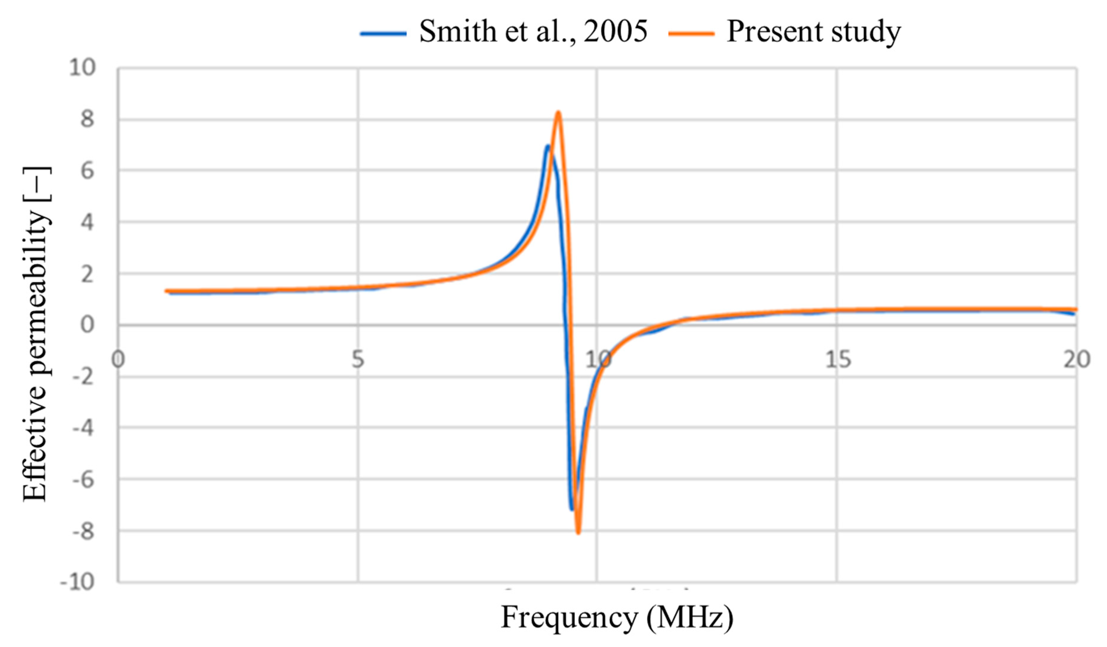
2.2. Effective Permeability
2.3. WPT Efficiency
3. Simulation and Experimental Studies
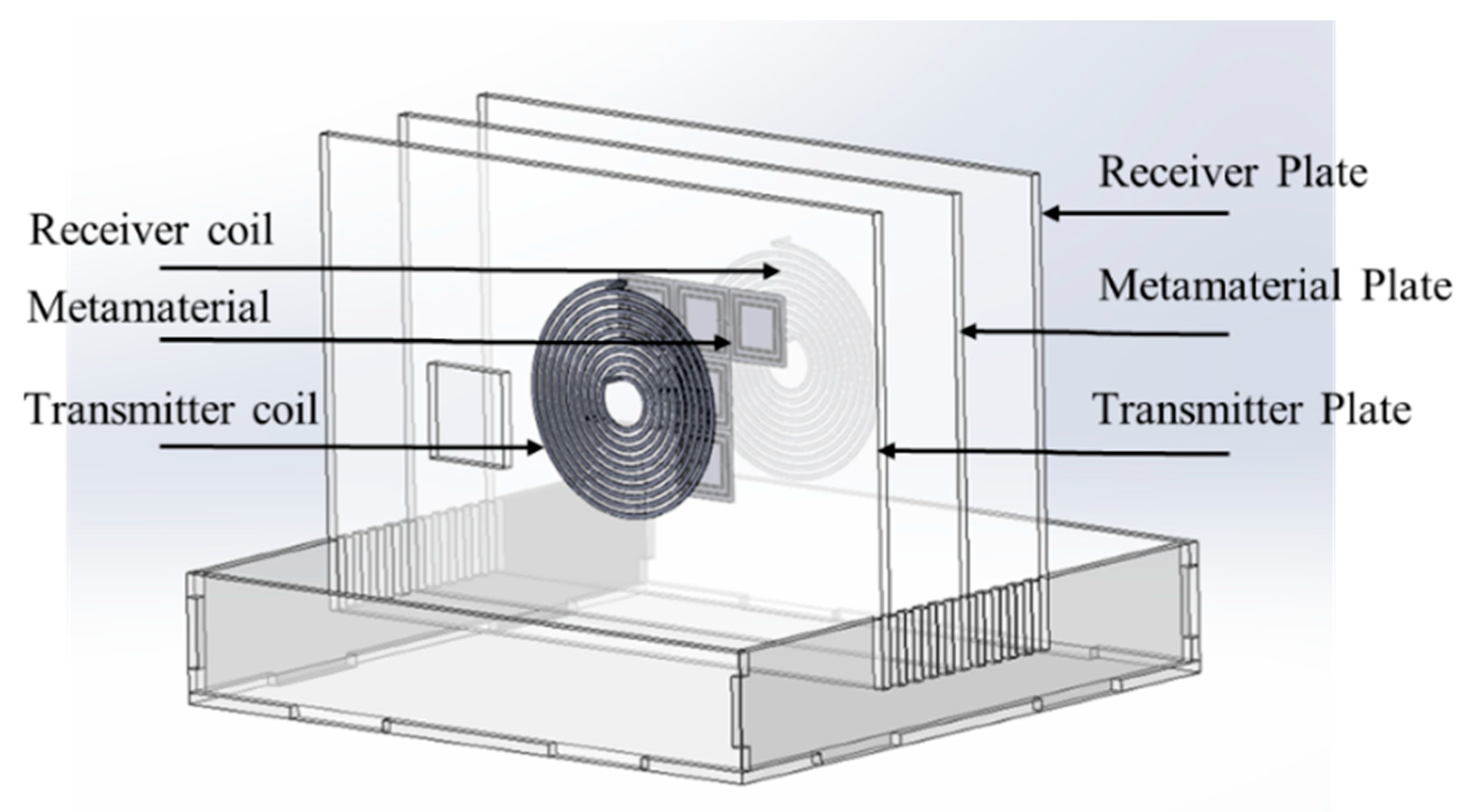
3.1. Simulation Study
3.2. Experimental Apparatus
4. Results and Discussion
4.1. Validation of MTM Model
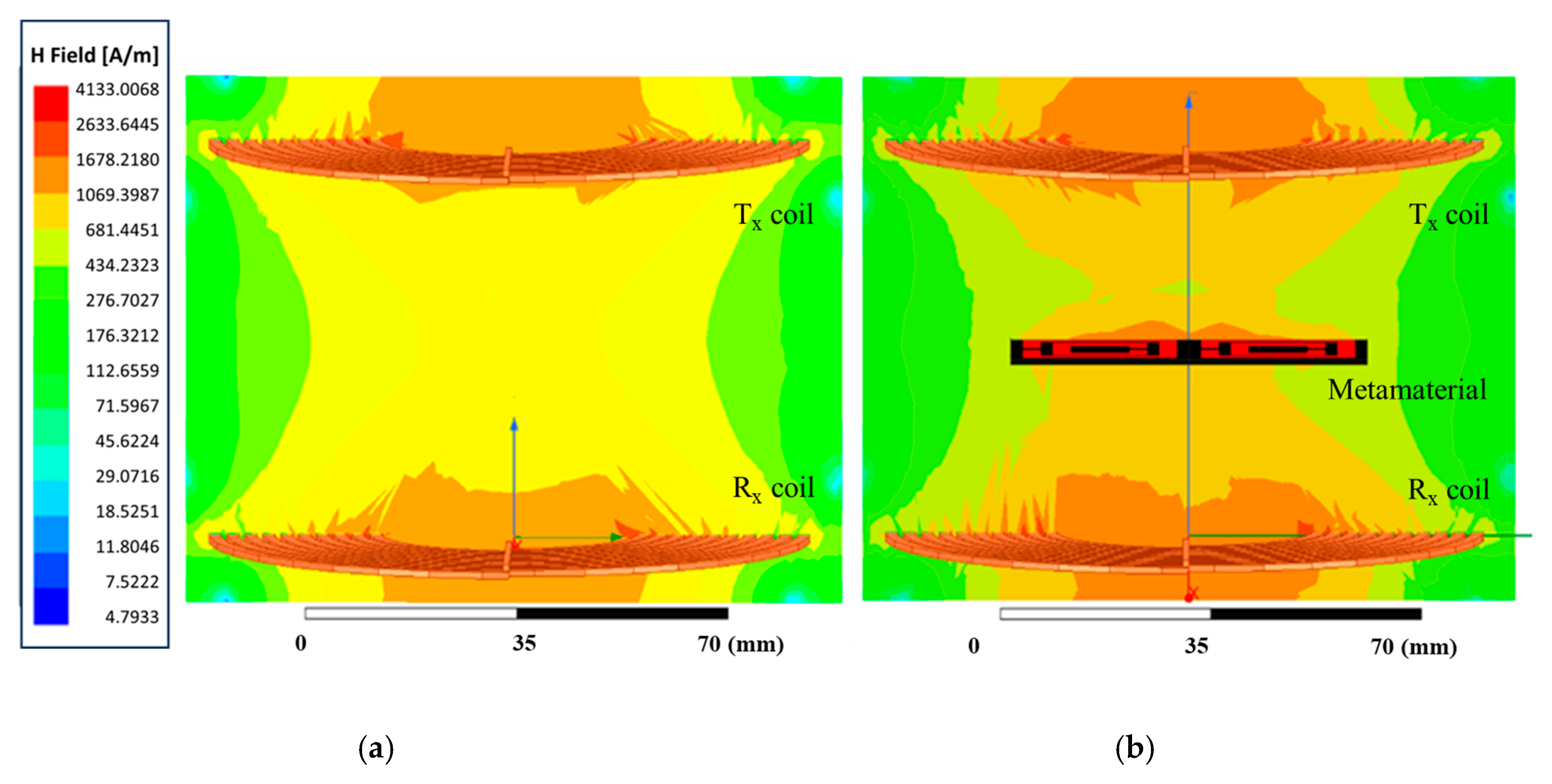
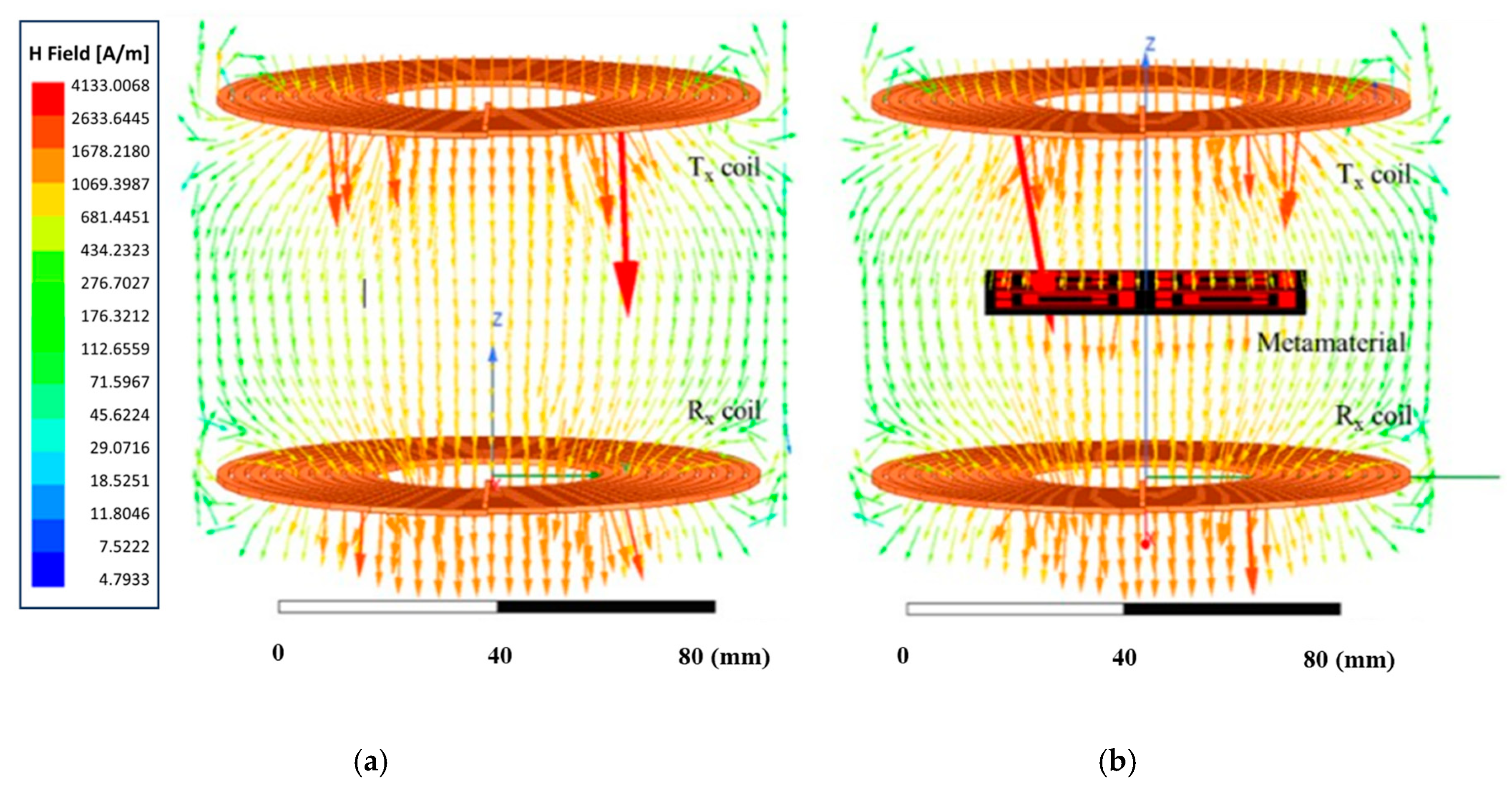
4.2. Enhancement of WPT Model with MTM
4.3. Effects of MTM Cell Number
4.4. Effects of MTM Cell Arrangement
5. Conclusions
Author Contributions
Funding
Data Availability Statement
Acknowledgments
Conflicts of Interest
References
- EEA. Greenhouse Gas Emissions from Transport in Europe. 2024. Available online: https://www.eea.europa.eu/en/analysis/indicators/greenhouse-gas-emissions-from-transport (accessed on 5 November 2024).
- EEA. 2021. Available online: https://www.eea.europa.eu/en/topics/in-depth/transport-and-mobility (accessed on 27 October 2024).
- European Environment Agency. Electric Vehicles in Europe. 2016. Available online: https://www.eea.europa.eu/en/analysis/publications/electric-vehicles-in-europe (accessed on 27 October 2024).
- Del Pero, F.; Delogu, M.; Pierini, M. Life Cycle Assessment in the automotive sector: A comparative case study of Internal Combustion Engine (ICE) and electric car. Procedia Struct. Integr. 2018, 12, 521–537. [Google Scholar] [CrossRef]
- Peng, T.; Ou, X.; Yan, X. Development and application of an electric vehicle’s life-cycle energy consumption and greenhouse gas emissions analysis model. Chem. Eng. Res. Des. 2018, 131, 699–708. Available online: https://www.eea.europa.eu (accessed on 27 February 2022). [CrossRef]
- Koengkan, M.; Fuinhas, J.A.; Teixeira, M.; Kazemzadeh, E.; Auza, A.; Dehdar, F.; Osmani, F. The Capacity of Battery-Electric and Plug-in Hybrid Electric Vehicles to Mitigate CO2 Emissions: Macroeconomic Evidence from European Union Countries. World Electr. Veh. J. 2022, 13, 58. [Google Scholar] [CrossRef]
- Kene, R.O.; Olwal, T.O. Energy Management and Optimization of Large-Scale Electric Vehicle Charging on the Grid. World Electr. Veh. J. 2023, 14, 95. [Google Scholar] [CrossRef]
- Song, M.; Jayathurathnage, P.; Zanganeh, E.; Krasikova, M.; Smirnov, P.; Belov, P.; Kapitanova, P.; Simovski, S.; Krasnok, A. Wireless power transfer based on novel physical concepts. Nat. Electron. 2021, 4, 707–716. [Google Scholar] [CrossRef]
- Yu, L.; Lin, P. Handware Architecture of Wireless Power Transfer, RFID and WIPT System. arXiv 2024, arXiv:2102.06876v1. [Google Scholar]
- Wisartpong, P. A review of wireless power transfer. Eng. Trans. 2021, 24, 161–169. [Google Scholar]
- Lerosey, G. Wireless power on the move. Nature 2017, 546, 354–355. [Google Scholar] [CrossRef] [PubMed]
- Kodeeswaran, S.; Nandhini Gayathri, M.; Peña-Alzola, R.; Sanjeevikumar, P.; Prasad, R. Electric Vehicle Wireless Charging—Design and Analysis Using Circuit Capacitive Coupler. 2017. Available online: https://Shorturl.asia/tDfSz (accessed on 20 October 2024).
- Pham, T.S.; Nguyen, T.D.; Tung, B.S.; Khuyen, B.X.; Hoang, T.T.; Ngo, Q.M.; Hiep, L.T.H.; Lam, V.D. Optimal frequency for magnetic resonant wireless power transfer in conducting medium. Sci. Rep. 2021, 11, 1–11. [Google Scholar] [CrossRef] [PubMed]
- Alhamrouni, I.; Iskandar, M.; Salem, M.; Awalin, L.J.; Jusoh, A.; Sutikno, T. Application of inductive coupling for wireless power transfer. Int. J. Power Electron. Drive Syst. 2020, 11, 1109–1116. [Google Scholar] [CrossRef]
- Zhou, H.; Zhu, B.; Hu, W.; Liu, Z.; Gao, X. Modelling and practical implementation of 2-Coil wireless power transfer systems. J. Electr. Comput. Eng. 2014, 1, 906537. [Google Scholar] [CrossRef]
- Bouanou, T.; Fadil, H.E.; Lassioui, A.; Assaddiki, O.; Njili, S. Analysis of Coil Parameters and Comparison of Circular, Rectangular, and Hexagonal Coils Used in WPT System for Electric Vehicle Charging. World Electr. Veh. J. 2021, 12, 45. [Google Scholar] [CrossRef]
- Nalinnopphakhun, P.; Onreabroy, W.; Kaewpradap, A. Parameter Effects on Induction Coil Transmitter of Wireless Charging Systems for Small Electric Motorcycle. In Proceedings of the 2018 IEEE International WIE Conference on Electrical and Computer Engineering (WIECON-ECE), Chonburi, Thailand, 14–16 December 2018; IEEE: Bangkok, Thailand, 2018. [Google Scholar] [CrossRef]
- Lee, W.S.; Oh, K.-S.; Yu, J.W. Distance-insensitive wireless power transfer and nearfield communication using a current-controlled loop with a loaded capacitance. IEEE Trans. Antennas Propag. 2014, 62, 936–940. [Google Scholar] [CrossRef]
- Bevacqua, M.T.; Bellizzi, G.G.; Merenda, M. An efficient far-field wireless power transfer via field intensity shaping techniques. Electronics 2021, 10, 1609. [Google Scholar] [CrossRef]
- Vatsala, V.; Alam, M.S.; Ahmad, A.; Chaban Rakan, C. Efficiency Enhancement of Wireless Charging for Electric Vehicles Through Reduction of Coil Misalignment. In Proceedings of the IEEE Transportation Electrification Conference and Expo (ITEC), Chicago, IL, USA, 22–24 June 2017; pp. 1–6. [Google Scholar]
- Lee, W.; Yoon, Y. Wireless Power Transfer Systems Using Metamaterials, University of Florida. IEEE Access 2020, 8, 147930–147947. [Google Scholar] [CrossRef]
- Amasiri, W.; Pijitrojana, W. Metamaterials for Optimizing Wireless Power Transfer. J. Sci. Technol. 2018, 27, 361–379. [Google Scholar] [CrossRef]
- Smith, D.R.; Vier, D.C.; Koschny, T.; Soukoulis, C.M. Electromagnetic parameter retrieval from inhomogeneous metamaterials, Physical Review E 25th Anniversary Milestones. Phys. Rev. E 2005, 71, 036617. [Google Scholar] [CrossRef] [PubMed]
- Li, G.; Lang, L.; Ren, J.; Fang, K.; Sun, Y.; Zhang, Y.; Li, Y.; Chen, H. Designment of wireless power transmitting system with magnetic megahertz metamaterials. In Proceedings of the IEEE Wireless Power Transfer Conference (WPTC), London, UK, 18–21 June 2019. [Google Scholar] [CrossRef]
- Smith, D.R.; Padilla, W.J.; Vier, D.C.; Nemat-Nasser, S.C.; Schultz, S. Composite Medium with Simultaneously Negative Permeability and Permittivity. Phys. Rev. Lett. 2000, 84, 4184. [Google Scholar] [CrossRef] [PubMed]
- Pendry, J.B.; Holden, A.J.; Robbins, D.J.; Stewart, W.J. Magnetism from conductors and enhanced nonlinear phenomena. Microwave theory and Techniques. IEEE Trans. Microw. Theory Tech. 1999, 47, 2075–2084. [Google Scholar] [CrossRef]
- Li, W.; Wang, P.; Yao, C.; Zhang, Y.; Tang, H. Experimental investigation of lD, 2D, and 3D metamaterials for efficiency enhancement in a 6.78MHz wireless power transfer system. In Proceedings of the IEEE Wireless Power Transfer Conference (WPTC), Aveiro, Portugal, 5–6 May 2016. [Google Scholar]
- Smith, D.R.; Schilling, J.R. Resonant Metamaterials: The Role of Split-Ring Resonators in Magnetic Field Enhancement. J. Appl. Phys. 2007, 102, 094503. [Google Scholar]


| Specifications | Value |
|---|---|
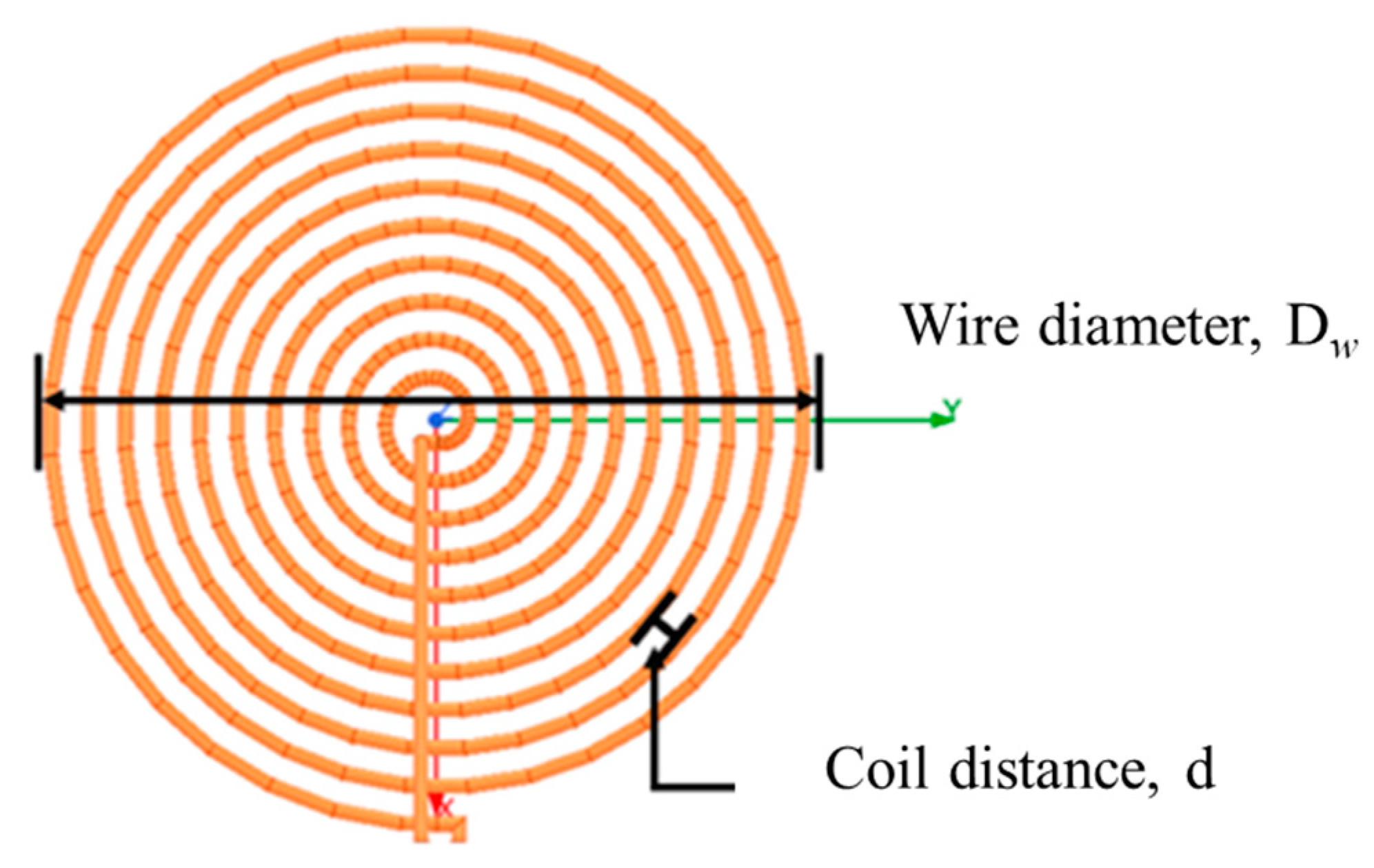
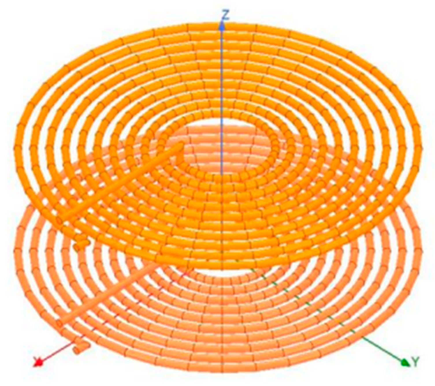
| Tx coil diameter DT (mm) | 1.3 |
| Rx coil diameter DR (mm) | 1.3 |
| Tx coil inductance LT (μH) | 4.6015 |
| Rx coil inductance LR (μH) | 2.7377 |
| Coupling coefficient K | 0.76 |
| MTM Specification | Parameter | Unit | Value |
|---|---|---|---|
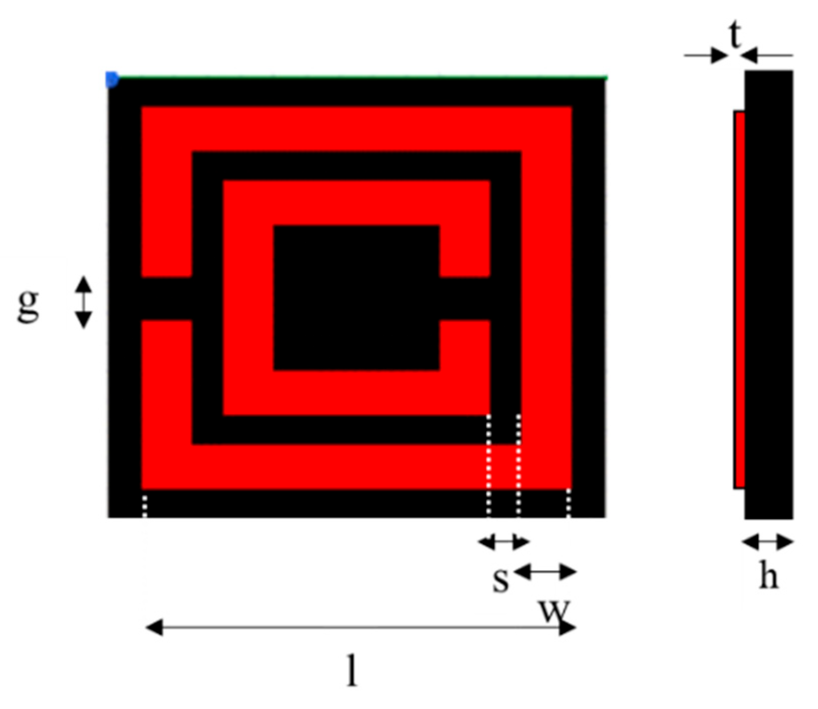
| Length of conductor ring | l | mm | 26.0 |
| Split gap | g | mm | 3.0 |
| Gap between conductor rings | s | mm | 2.0 |
| Substrate thickness | h | mm | 0.8 |
| Conductor width | w | mm | 3.0 |
| Thickness of the conductor | t | mm | 0.035 |
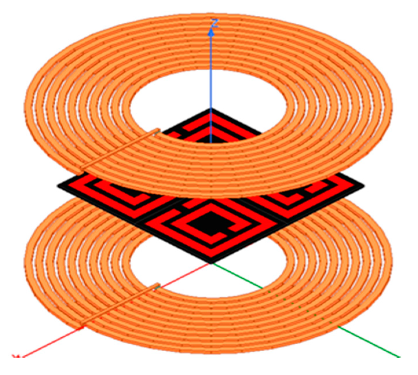
| Number of rings | N | - | 2 |
| PCB material | - | - | Copper |
| Substrate material | - | - | FR-4 |
| Specifications | Case 1 | Case 2 |
|---|---|---|
| Tx coil diameter DT (mm) | 1.3 | 1.3 |
| Rx coil diameter DR (mm) | 1.3 | 1.3 |
| Coil distance d (mm) | 0 | 2 |
| PTE ηPTE (%) | 97.86 | 93.58 |
| Load (Ω) | ηPTE |
|---|---|
| 1 | 65.27% |
| 2 | 76.14% |
| 3 | 71.55% |
| 4 | 84.19% |
| 5 | 96.90% |
| Simulation | 97.86% |
Disclaimer/Publisher’s Note: The statements, opinions and data contained in all publications are solely those of the individual author(s) and contributor(s) and not of MDPI and/or the editor(s). MDPI and/or the editor(s) disclaim responsibility for any injury to people or property resulting from any ideas, methods, instructions or products referred to in the content. |
© 2025 by the authors. Published by MDPI on behalf of the World Electric Vehicle Association. Licensee MDPI, Basel, Switzerland. This article is an open access article distributed under the terms and conditions of the Creative Commons Attribution (CC BY) license (https://creativecommons.org/licenses/by/4.0/).
Share and Cite
Onreabroy, W.; Piemsomboon, S.; Traikunwaranon, S.; Wilaiprajuabsang, N.; Kaewpradap, A. Enhancing Wireless Power Transfer Efficiency Through Innovative Metamaterial Configurations for Electric Vehicles. World Electr. Veh. J. 2025, 16, 48. https://doi.org/10.3390/wevj16010048
Onreabroy W, Piemsomboon S, Traikunwaranon S, Wilaiprajuabsang N, Kaewpradap A. Enhancing Wireless Power Transfer Efficiency Through Innovative Metamaterial Configurations for Electric Vehicles. World Electric Vehicle Journal. 2025; 16(1):48. https://doi.org/10.3390/wevj16010048
Chicago/Turabian StyleOnreabroy, Wandee, Supatsara Piemsomboon, Suneerat Traikunwaranon, Naksit Wilaiprajuabsang, and Amornrat Kaewpradap. 2025. "Enhancing Wireless Power Transfer Efficiency Through Innovative Metamaterial Configurations for Electric Vehicles" World Electric Vehicle Journal 16, no. 1: 48. https://doi.org/10.3390/wevj16010048
APA StyleOnreabroy, W., Piemsomboon, S., Traikunwaranon, S., Wilaiprajuabsang, N., & Kaewpradap, A. (2025). Enhancing Wireless Power Transfer Efficiency Through Innovative Metamaterial Configurations for Electric Vehicles. World Electric Vehicle Journal, 16(1), 48. https://doi.org/10.3390/wevj16010048