
Predictive Torque Control of Permanent Magnet Motor for New-Energy Vehicles Under Low-Carrier-Ratio Conditions


Abstract
1. Introduction
2. Traditional Model Predictive Torque Control
2.1. PMSM Mathematical Model
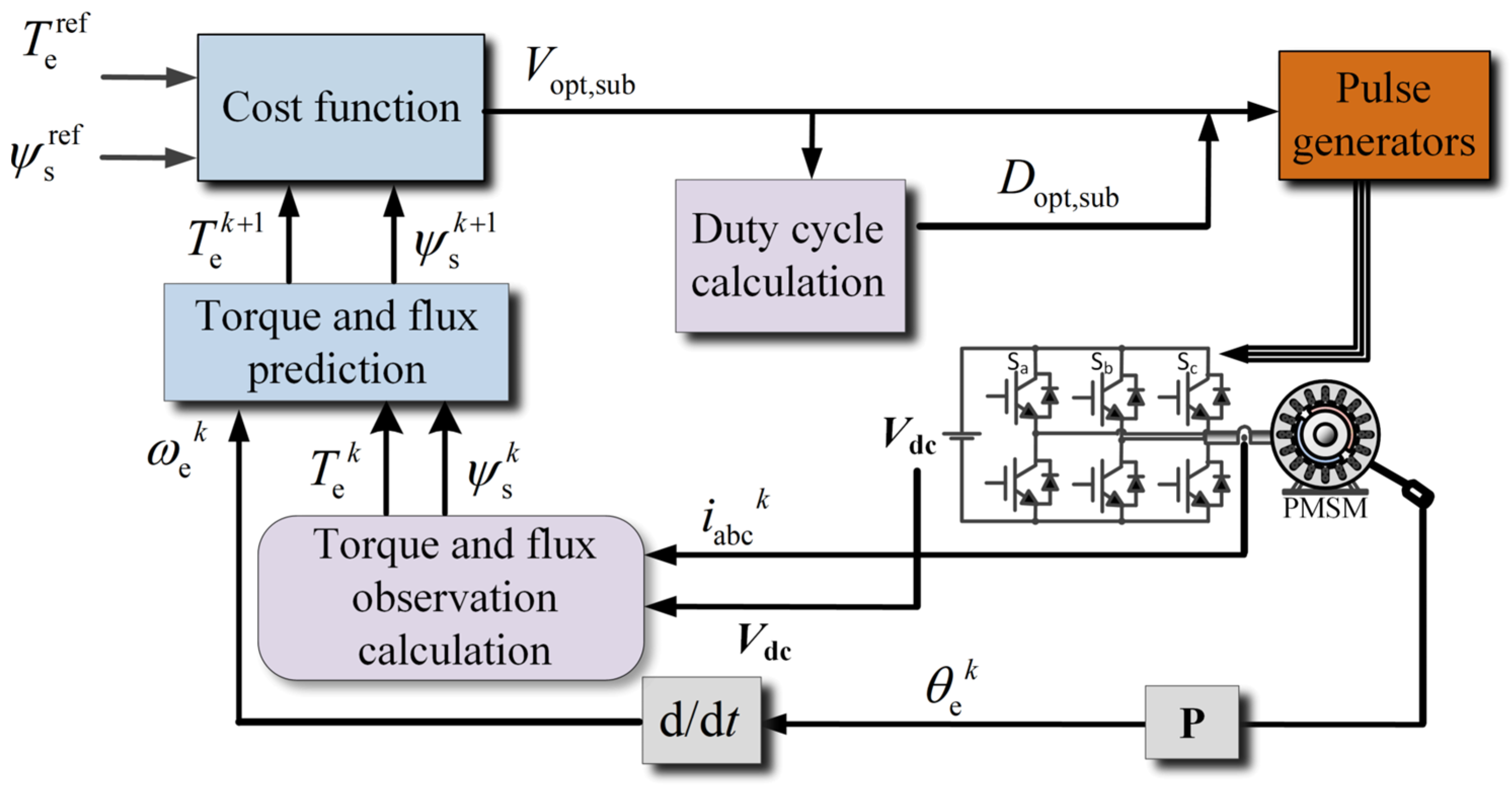
2.2. Traditional Model Predictive Torque Control Principle
3. Model Predictive-Torque-Control Method for Low Carrier Ratio Operating Conditions
3.1. Predictive Torque Control Model for Low-Carrier-Ratio Conditions
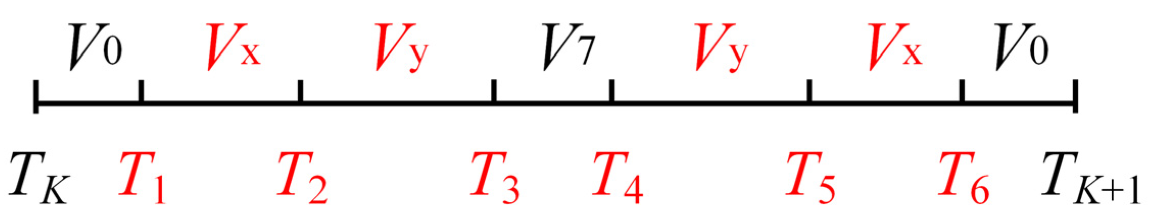
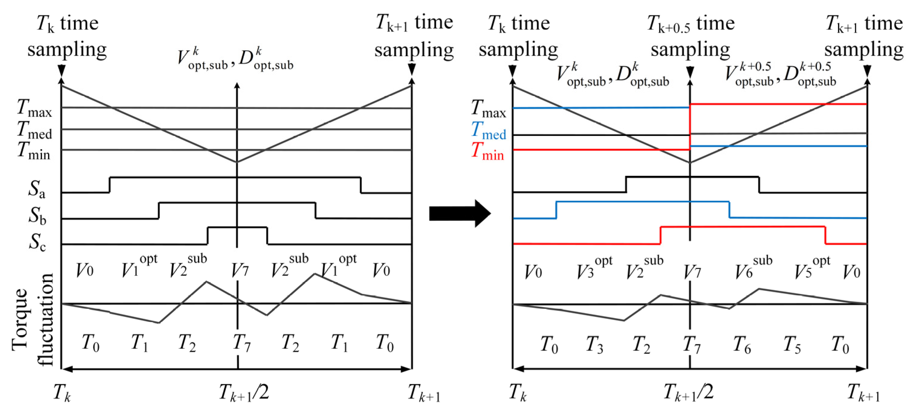
3.2. Model Predictive-Torque-Control Strategy Based on Optimal Vector-Action Combination
3.2.1. Analysis of Optimal Vector-Action-Combination Strategies
3.2.2. Optimal Duty Cycle Calculation Method
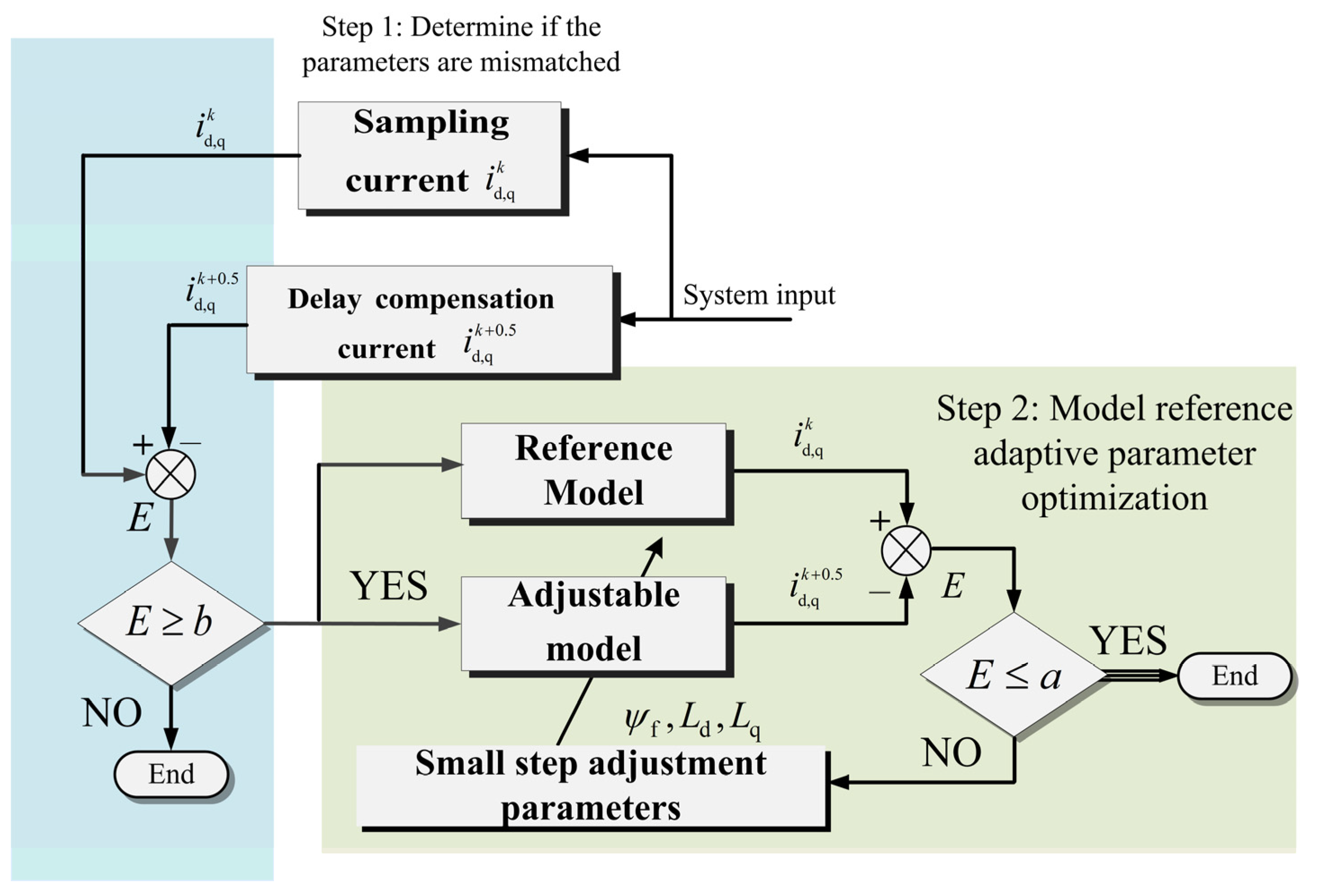
3.2.3. Online Parameter Optimization Strategy
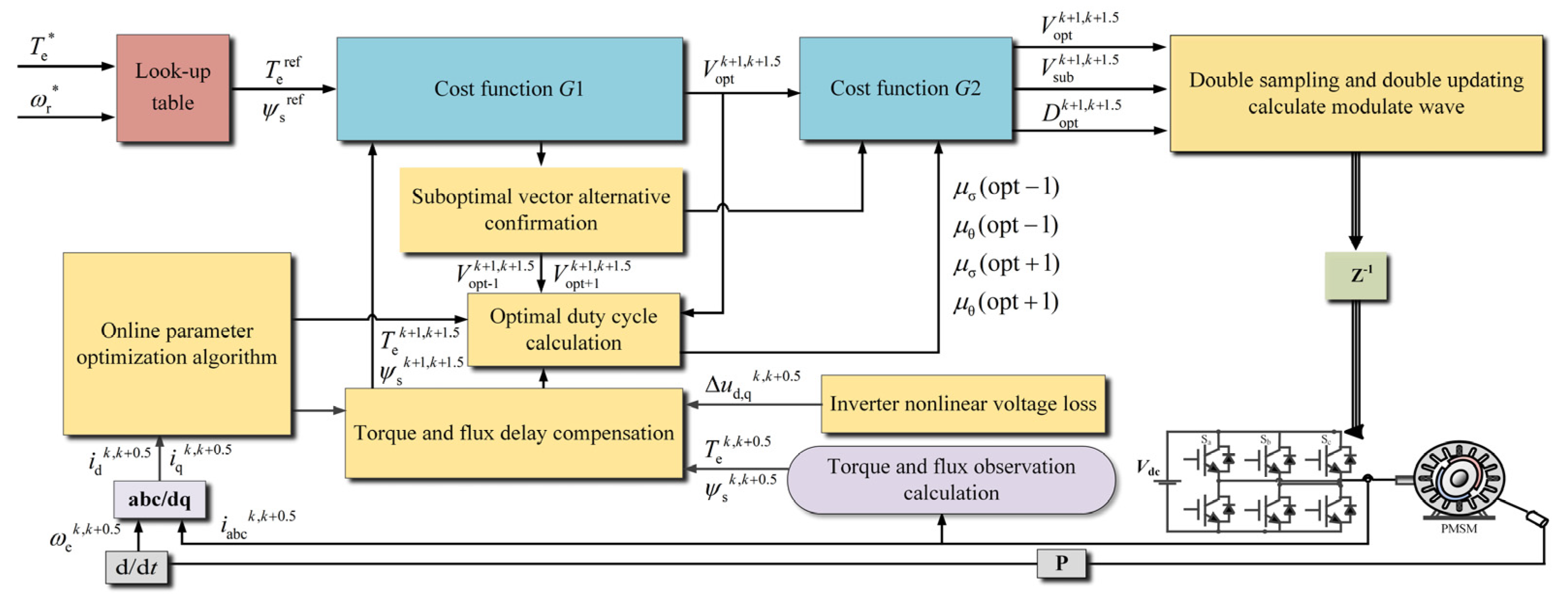
3.3. Algorithmic Implementation
4. Results
5. Conclusions
- (1)
- This paper analyzes the reasons why the predictive model based on the forward Euler method struggles to achieve accurate torque control under low-carrier-ratio conditions from the perspective of model errors and establishes a motor discrete model considering the rotor position variation. This model is applied to the delay-compensation section and the selection of the optimal-vector-action-combination section.
- (2)
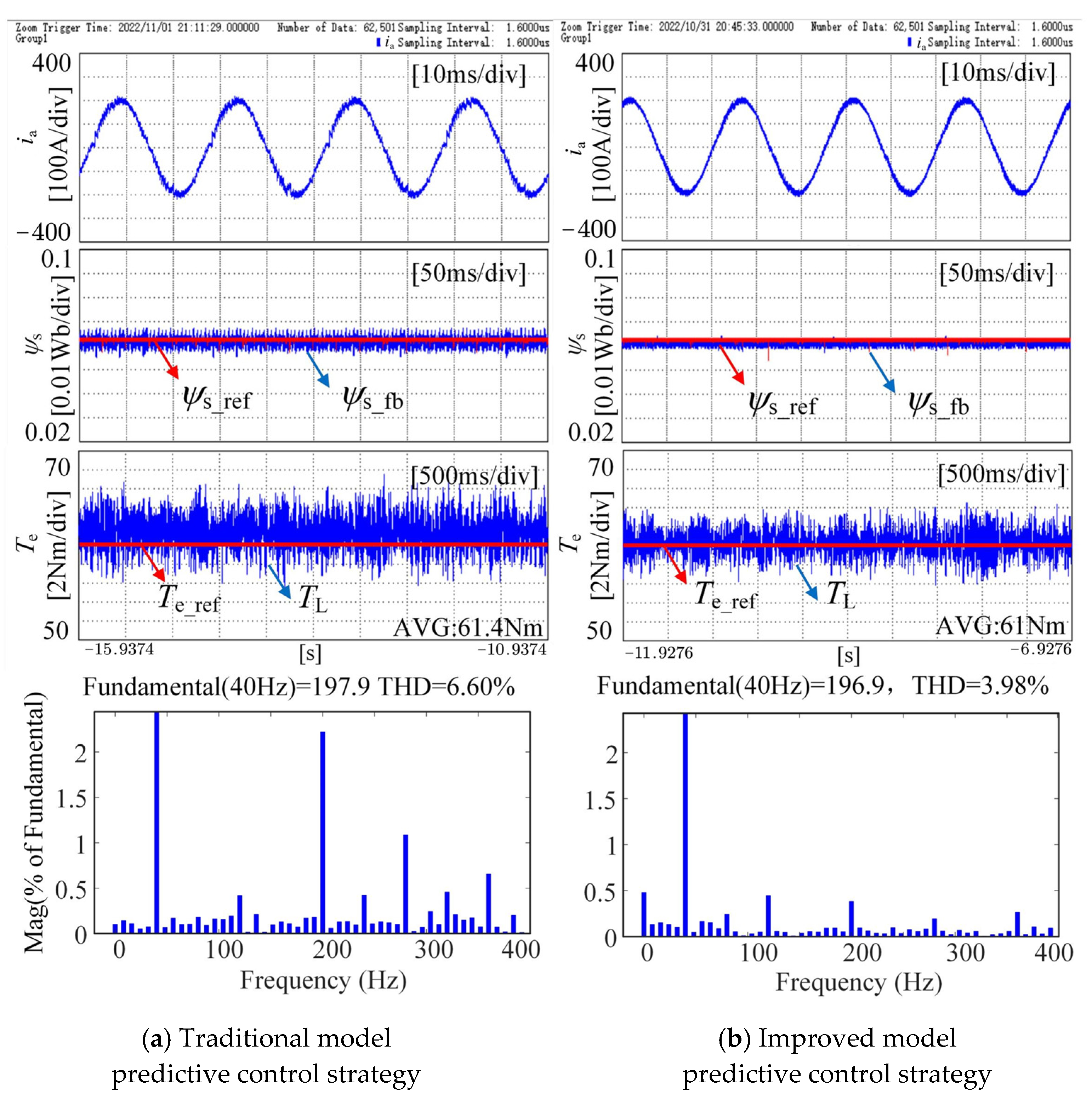
- The cascade relationship between the voltage vector and the duty cycle is improved, and the optimal duty cycle calculation method is proposed, which is combined with the improved duty cycle updating method to further improve the algorithm accuracy. Using a unit carrier as the analysis period, the oversampling algorithm ensures that the selected voltage vector and interaction time form an optimal combination throughout the entire carrier cycle.
- (3)
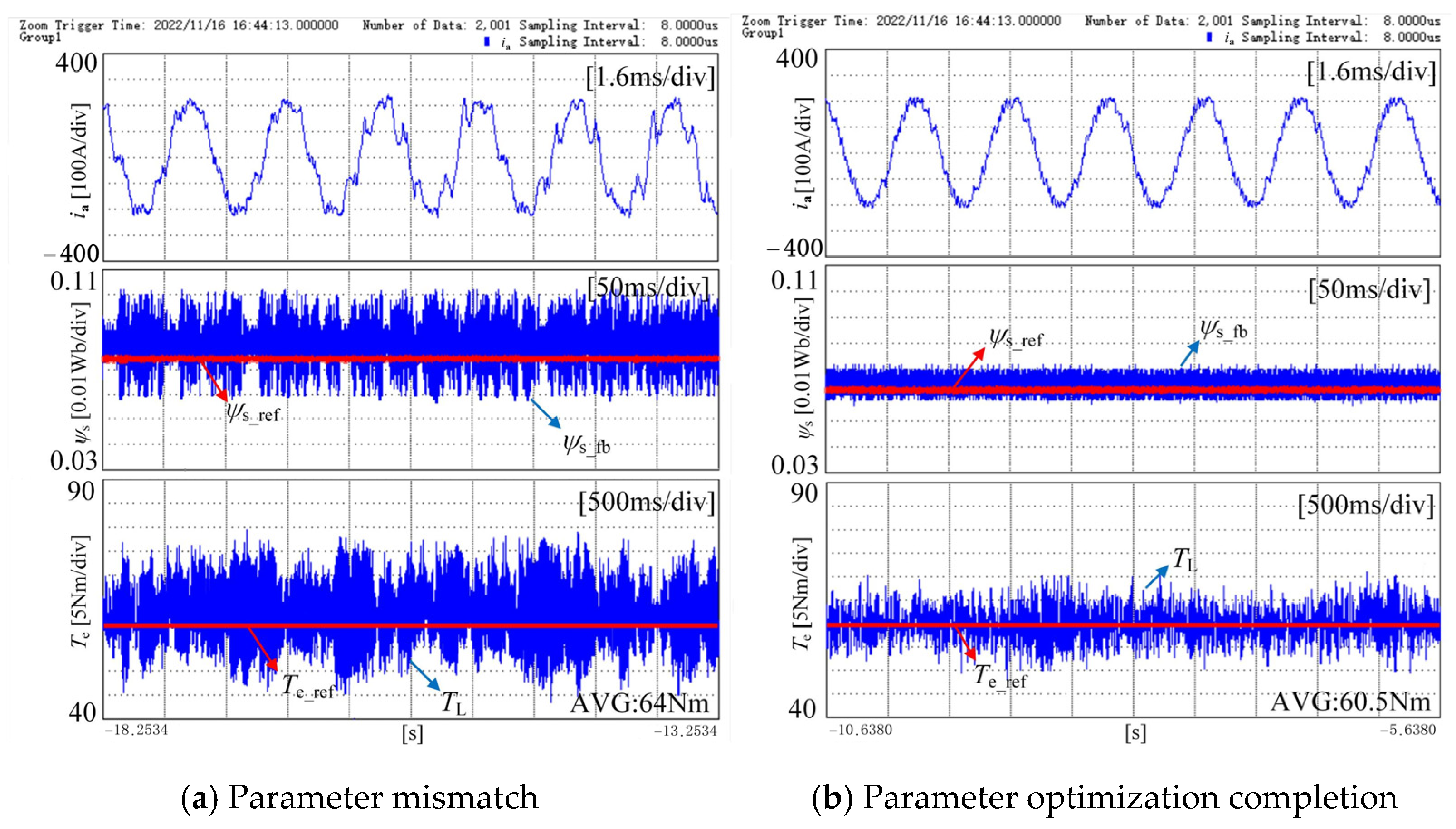
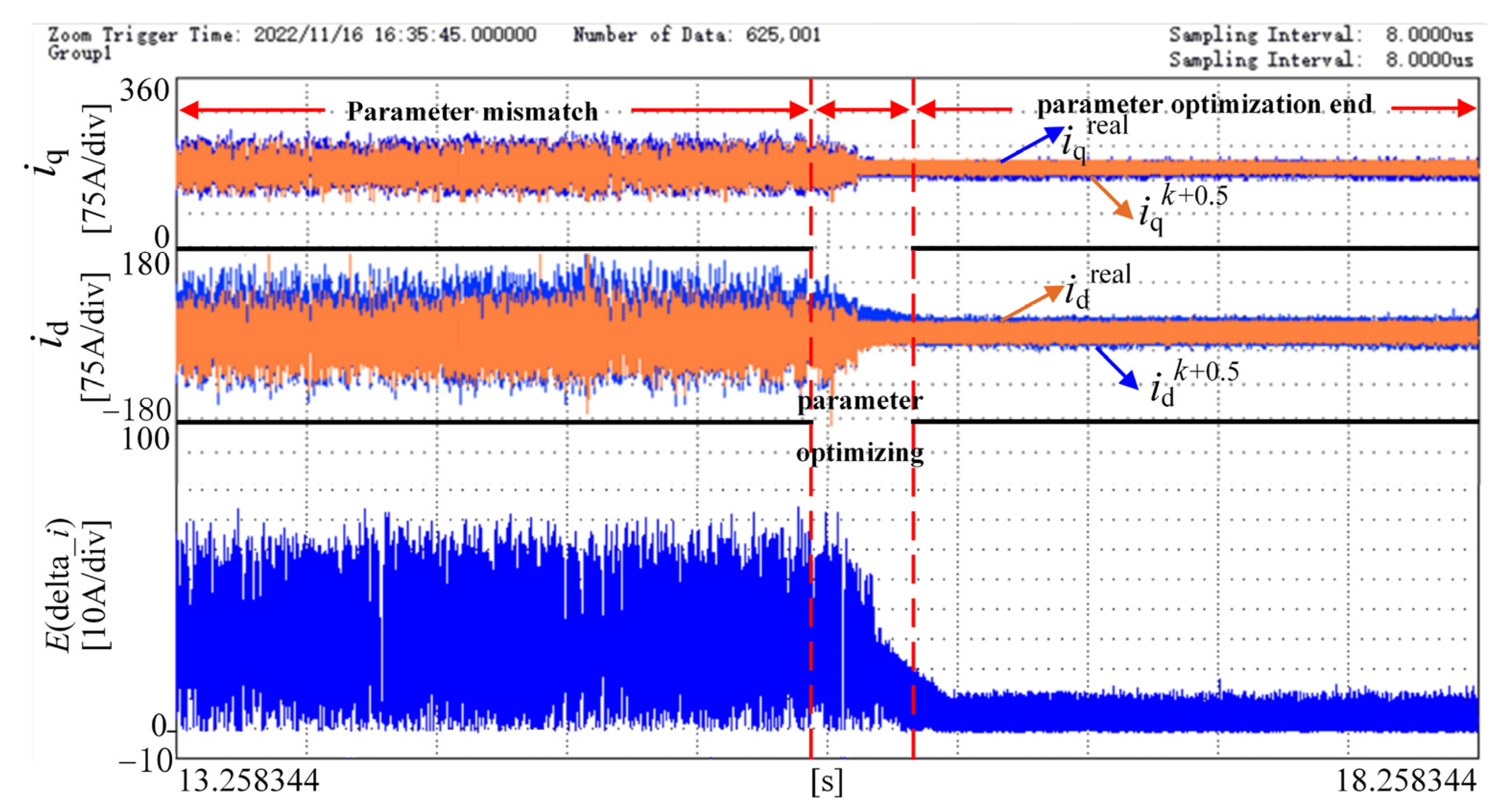
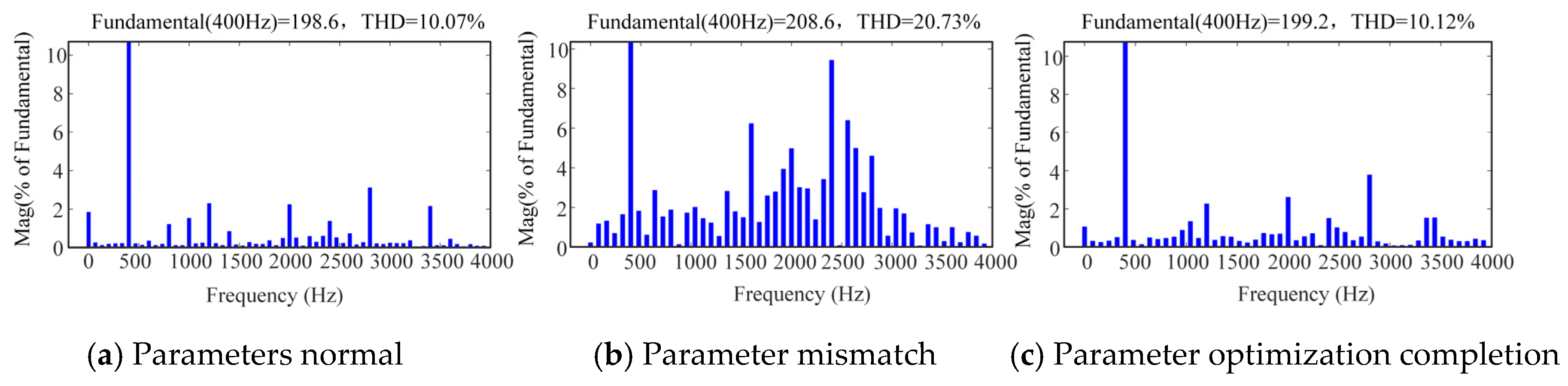
- The parameter sensitivity of the model predictive-torque-control strategy is analyzed, and an online parameter optimization algorithm is proposed. The parameter optimization algorithm not only ensures the accuracy of the algorithm during motor operation but also resolves the modeling errors caused by neglecting the resistance voltage drop to some extent. Experimental results demonstrate that the addition of this section is beneficial for solving the problem of decreased torque control accuracy caused by parameter mismatch occurs.
Author Contributions
Funding
Data Availability Statement
Conflicts of Interest
Variables
| Variable Symbol | Description | Unit | Variable Symbol | Description | Unit |
| d-axis stator voltage | V | θ | Rotor position angle | rad | |
| q-axis stator voltage | V | θ1 | Phase angle of vector 1 in α-β axis | rad | |
| d-axis stator current | A | DC bus voltage | V | ||
| q-axis stator current | A | − | Duration of vector 1 action in the first half of the carrier cycle | s | |
| ωe | Rotor electrical angular velocity | rad/s | Phase angle of effective vector Vx in α-β axis | rad | |
| d-axis stator flux linkage | Wb | Phase angle of effective vector Vy in α-β axis | rad | ||
| q-axis stator flux linkage | Wb | Ld0 | Nominal value of d-axis inductance | mH | |
| Rs | Stator resistance | Ω | Lq0 | Nominal value of q-axis inductance | mH |
| Electromagnetic torque | N·m | Nominal value of permanent flux linkage | Wb | ||
| Number of pole pairs | - | Actual value of permanent flux linkage | Wb | ||
| Control period | s | E | System error | - | |
| d-axis inductance | mH | Optimal vector duty cycle | - | ||
| q-axis inductance | mH | Suboptimal vector duty cycle | - | ||
| λ | Weighting factor of the cost function | - | Δ | Error due to parameter mismatch and inverter nonlinearity | - |
| Error in d-axis flux linkage | Wb | Error in q-axis flux linkage | Wb | ||
| a | Lower threshold for parameter optimization error | - | b | Upper threshold for parameter optimization error | - |
| Actual sampled d-axis current | A | Actual sampled q-axis current | A | ||
| Delay-compensated predicted d-axis current | A | Delay-compensated predicted q-axis current | A | ||
| THD | Total Harmonic Distortion of current | % |
References
- Wang, L.; Zhu, Z.Q.; Bin, H.; Gong, L.M. Current harmonics suppression strategy for PMSM with nonsinusoidal Back-EMF based on adaptive linear neuron method. IEEE Trans. Ind. Electron. 2020, 67, 9164–9173. [Google Scholar] [CrossRef]
- Xia, C.; Liu, T.; Shi, T.; Song, Z. A Simplified Finite-Control-Set Model-Predictive Control for Power Converters. IEEE Trans. Ind. Inform. 2014, 10, 991–1002. [Google Scholar]
- Shen, K.; Zhang, J.; Wang, J. A Model Predictive Control Scheme of Multi-step Prediction Finite Control Set for Converters. Proc. CSEE 2012, 32, 37–44+173. [Google Scholar]
- Zhang, Y.; Yin, Z.; Li, W.; Liu, J.; Zhang, Y. Adaptive Sliding-Mode-Based Speed Control in Finite Control Set Model Predictive Torque Control for Induction Motors. IEEE Trans. Power Electron. 2021, 36, 8076–8087. [Google Scholar] [CrossRef]
- Zhang, X.G.; Zhang, L.; Hou, B.S. Improved Model Predictive Torque Control of Permanent Magnet Synchronous Motor. Proc. CSEE 2017, 37, 4800–4809+4905. [Google Scholar]
- Khalilzadeh, M.; Vaez-Zadeh, S. A Robust Predictive Torque and Flux Control for IPM Motor Drives Without a Cost Function. IEEE Trans. Power Electron. 2021, 36, 8067–8075. [Google Scholar] [CrossRef]
- Chen, W.; Zeng, S.; Zhang, G. Improved Three-Vector Model Predictive Torque Control of Permanent Magnet Synchronous Motor. Trans. China Electrotech. Soc. 2018, 33, 420–426. [Google Scholar]
- Zhang, X.; Hou, B. Double Vectors Model Predictive Torque Control Without Weighting Factor Based on Voltage Tracking Error. IEEE Trans. Power Electron. 2018, 33, 2368–2380. [Google Scholar] [CrossRef]
- Zhang, Y.C.; Yang, H.T. Generalized two- vector-based model-predictive torque control of induction motor drives. IEEE Trans. Power Electron. 2015, 30, 3818–3829. [Google Scholar] [CrossRef]
- Zhou, Z.; Xia, C.; Yan, Y.; Wang, Z.; Shi, T. Torque Ripple Minimization of Predictive Torque Control for PMSM With Extended Control Set. IEEE Trans. Ind. Electron. 2017, 64, 6930–6939. [Google Scholar] [CrossRef]
- Li, X.; Xue, Z.; Zhang, L.; Hua, W. A Low-Complexity Three-Vector-Based Model Predictive Torque Control for SPMSM. IEEE Trans. Power Electron. 2021, 36, 13002–13012. [Google Scholar] [CrossRef]
- Bae, B.H.; Sul, S.K. A compensation method for time delay of full-digital synchronous frame current regulator of PWM AC drives. IEEE Trans. Ind. Appl. 2003, 39, 802–810. [Google Scholar] [CrossRef]
- Jarzebowicz, L. Errors of a Linear Current Approximation in High-Speed PMSM Drives. IEEE Trans. Power Electron. 2017, 32, 8254–8257. [Google Scholar] [CrossRef]
- Yan, Y.; Zhao, M.; Chen, Z.; Li, M.; Shi, T. Low Frequency Ratio Deadbeat Predictive Torque Control of Permanent Magnet Synchronous Motor in Auxiliary Coordinate System. Proc. CSEE 2023, 43, 761–770. [Google Scholar]
- Yuan, Q.; Dong, S.; Shi, J.; Zhong, C. Current Loop Internal Model Decoupling Control for Permanent Magnet Synchronous Motor Under Low Carrier Ratio. Power Electron. Technol. 2024, 58, 31–35. [Google Scholar]
- Sun, X.D.; Wu, C.; Wang, J.Y. Adaptive Compensation Flux Observer of Permanent Magnet Synchronous Motors At Low Carrier Ratio. IEEE Trans. Power Electron. 2021, 36, 2747–2760. [Google Scholar] [CrossRef]
- Gu, S.; Shen, J. Decoupling Control of High-Speed Permanent Magnet Synchronous Motor—Digital Delay and Smith Predictive Control at Low Carrier Ratio. Micro Mot. 2024, 57, 18–25. [Google Scholar]
- Stolze, P.; Kramkowski, M.; Mouton, T.; Tomlinson, M.; Kennel, R. Increasing the performance of Finite-Set Model Predictive Control by oversampling. In Proceedings of the 2013 IEEE International Conference on Industrial Technology (ICIT), Cape Town, South Africa, 25–28 February 2013; pp. 551–556. [Google Scholar]
- Xu, F.B.; Zhong, R.F.; Sun, W.; Jin, M.J.; Shen, J.X. Improved topology of PMSGPWM rectifier with low carrier ratio. Electr. Mach. Control 2018, 22, 41–48. [Google Scholar]
- Lan, Z.; Wang, B.; Xu, C.; Li, L. A Novel Three-Vector Model Predictive Current Control for Permanent Magnet Synchronous Motor. Proc. CSEE 2018, 38, 7507–7517. [Google Scholar]
- Zhang, Y.C.; Yang, H.T.; Wei, X.L. Model Predictive Control of Permanent Magnet Synchronous Motors Based on Fast Vector Selection. Trans. China Electrotech. Soc. 2016, 31, 66–73. [Google Scholar]
- Feng, L.; Fu, J.; Liao, L.; Wen, Y.; Song, W. An Improved Low Switching Frequency Model Predictive Direct Torque Control Strategy for Traction Permanent Magnet Synchronous Motor. Proc. CSEE 2021, 41, 7507–7517. [Google Scholar]
- Yao, X.L.; Ma, C.W.; Wang, J.F. Robust Model Predictive Current Control for PMSM Based on Prediction Error Compensation. Proc. CSEE 2021, 41, 6071–6081. [Google Scholar]
- Nguyen, H.T.; Jung, J.W. Finite Control Set Model Predictive Control to Guarantee Stability and Robustness for Surface-Mounted PM Synchronous Motors. IEEE Trans. Ind. Electron. 2018, 65, 8510–8519. [Google Scholar] [CrossRef]
- Xu, Y.P.; Wang, J.; Zhou, Q.; Zhang, B. Double optimization three-vector-based model predictive current control for Permanent Magnet Synchronous Motors. Proc. CSEE 2018, 38, 1857–1864+1923. [Google Scholar]
- Guo, J.; Fan, T.; Zhang, H.; Bian, Y.; Wen, X. Stability Analysis of Permanent Magnet Synchronous Motor Current Loop Control at High Speed and Low Carrier Ratio. Proc. CSEE 2019, 39, 7336–7346+7506. [Google Scholar]
- Sun, J.; Wang, Z.; Gu, X.; Xia, C. Predictive Current Control of PMSM with High Speed and Low frequency ratio. Proc. CSEE 2020, 40, 3663–3673. [Google Scholar]
- Wang, Z.; Xie, S.; Jin, X.; Shi, T.; Yang, M. A novel deadbeat predictive current control of permanent magnet synchronous motor based on oversampling scheme. IET Power Electron. 2021, 15, 1029–1044. [Google Scholar] [CrossRef]
- Qin, Y.; Yan, Y.; Chen, W.; Geng, Q. Three-Vector Model Predictive Current Control Strategy for Permanent Magnet Synchronous Motor Drives with Parameter Error Compensation. Trans. China Electrotech. Soc. 2020, 35, 255–265. [Google Scholar]
- Townsend, C.D.; Mirzaeva, G.; Goodwin, G.C. Deadtime Compensation for Model Predictive Control of Power Inverters. IEEE Trans. Power Electron. 2017, 32, 7325–7337. [Google Scholar] [CrossRef]
- Yao, X.; Huang, C.; Wang, J. A two-vector-based model predictive current control with online parameter identification for PMSM drives. Proc. CSEE 2023, 43, 9319–9330. (In Chinese) [Google Scholar]


| Parameters | Symbolic Representation | Value |
|---|---|---|
| Rated voltage/V | Vdc | 320 |
| Rated torque/(N·m) | Te | 72 |
| Rated speed/(r/min) | n | 3000 |
| Pole pairs | Pn | 4 |
| d-axis inductance Ld/mH | Ld | 0.1099 |
| q-axis inductance Lq/mH | Lq | 0.3453 |
| Flux linkage/Wb | ψf | 0.038749 |
| Stator resistance/Ω | Rs | 0.03 |
| Average Torque Tracking Error | Total Harmonic Distortion (THD)/% | |
|---|---|---|
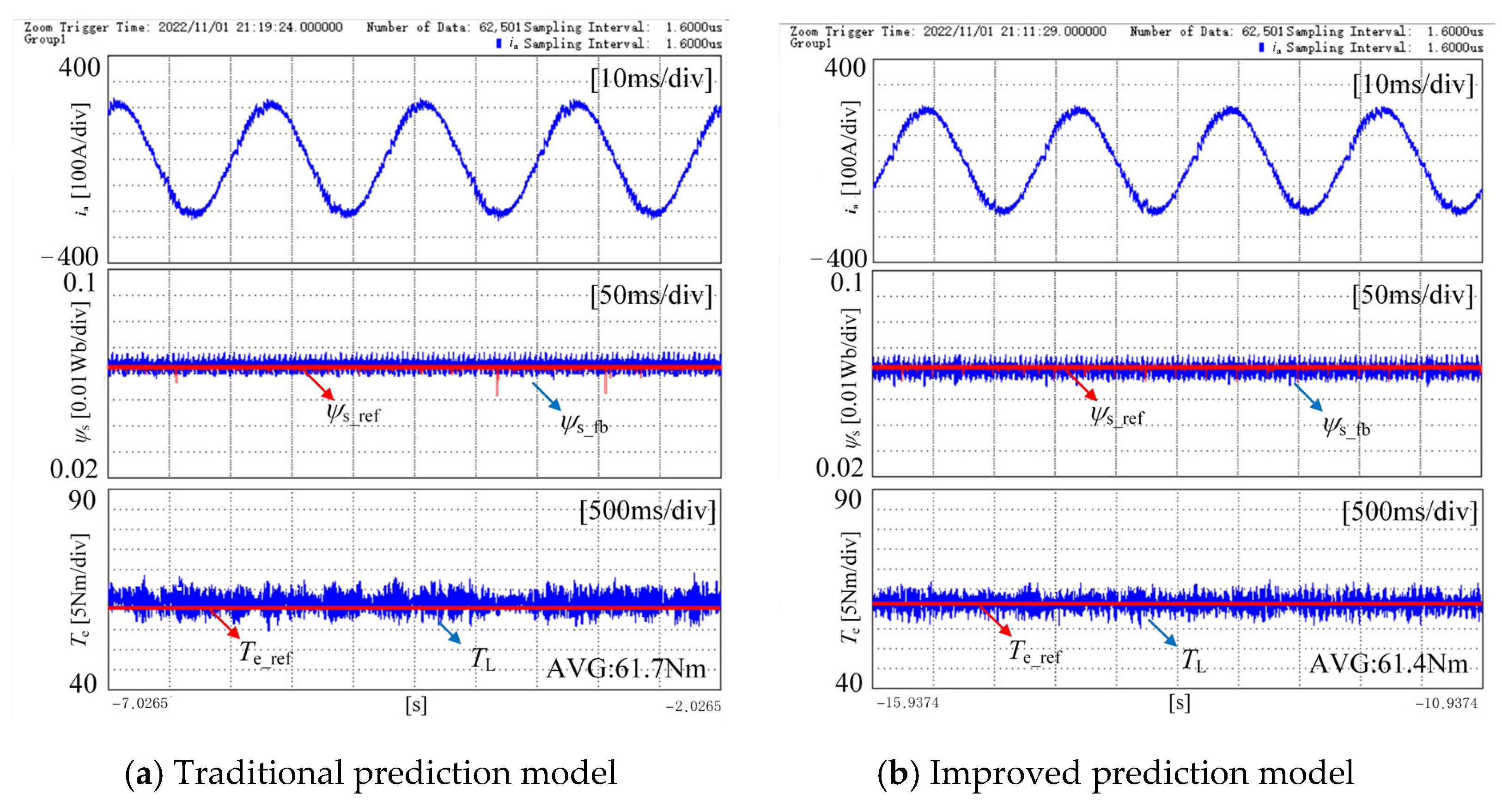
| Traditional strategy | 2.33% | 6.60 |
| Improved strategy | 1.67% | 3.98 |
| Average Torque Tracking Error | Total Harmonic Distortion (THD)/% | |
|---|---|---|
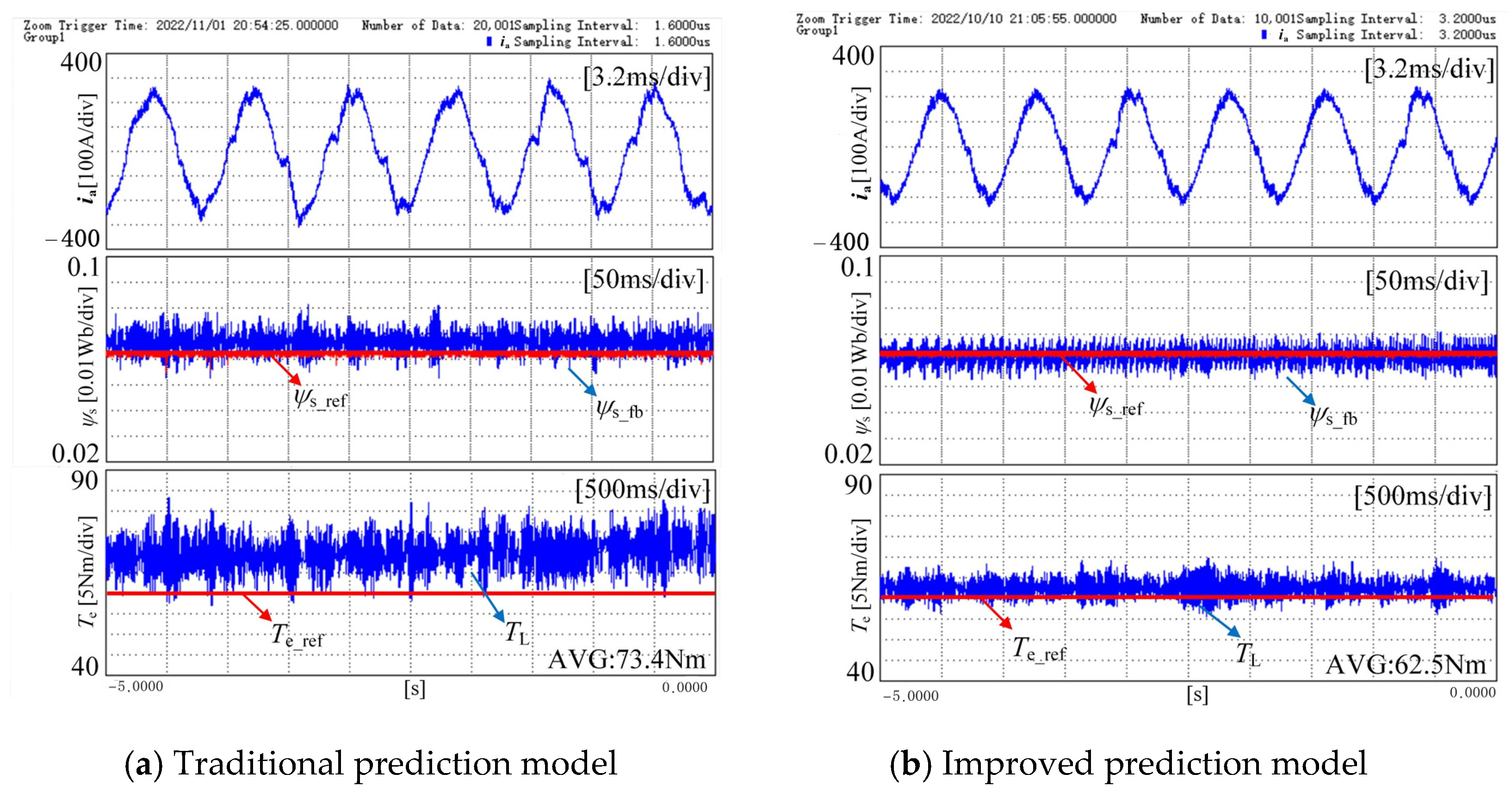
| Traditional strategy | 4.17% | 13.36 |
| Improved strategy | 1.17% | 7.86 |
| Average Torque Tracking Error | Total Harmonic Distortion (THD)/% | |
|---|---|---|
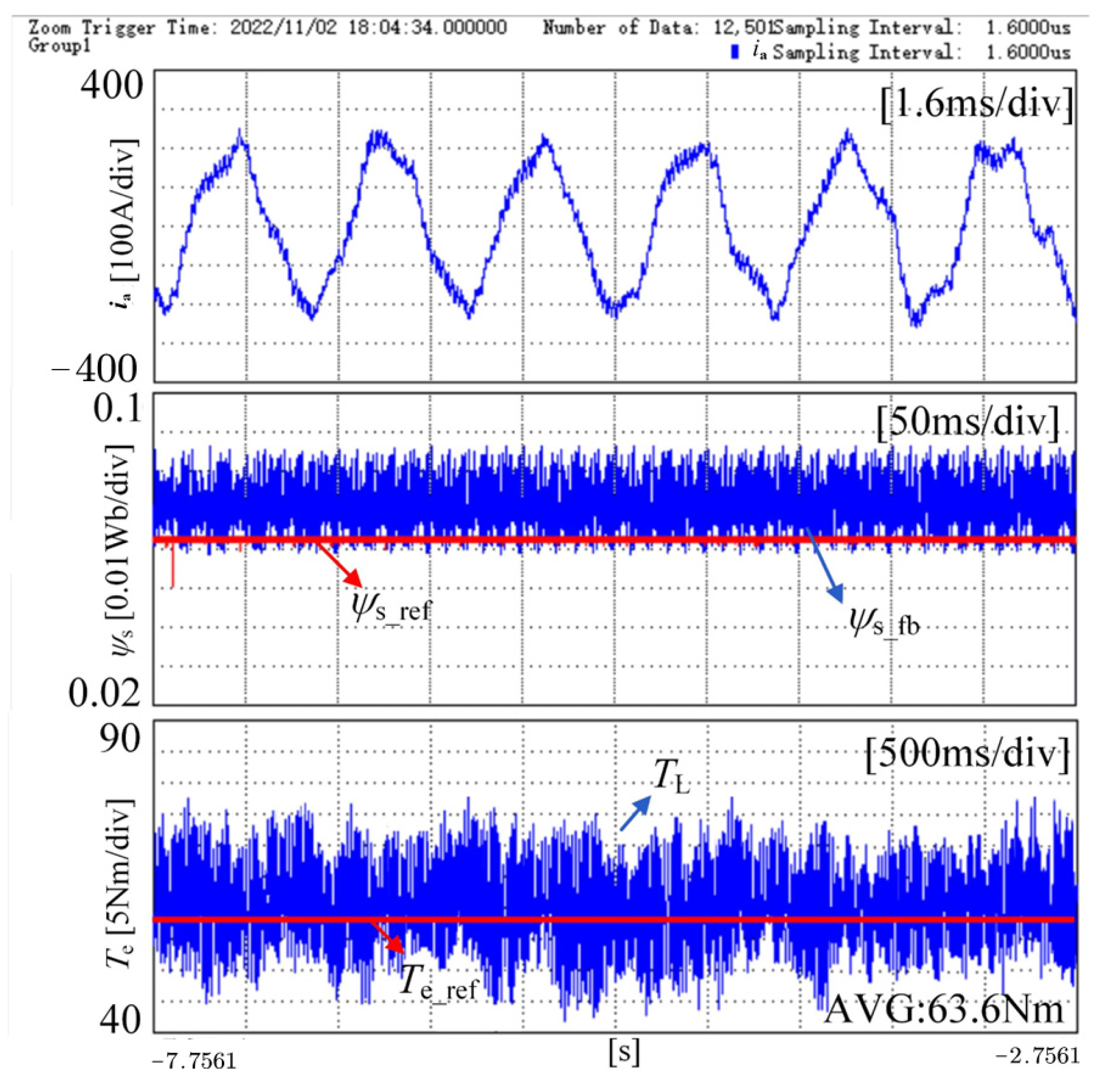
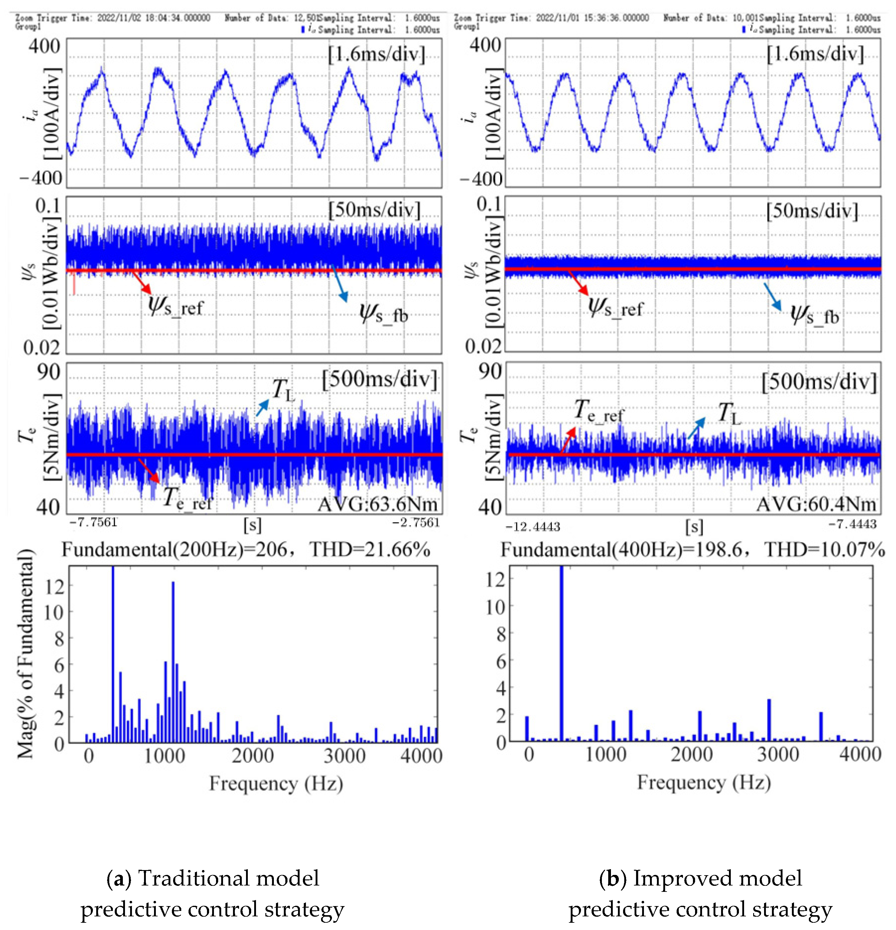
| Traditional strategy | 6.00% | 21.66 |
| Improved strategy | 0.67% | 10.07 |
Disclaimer/Publisher’s Note: The statements, opinions and data contained in all publications are solely those of the individual author(s) and contributor(s) and not of MDPI and/or the editor(s). MDPI and/or the editor(s) disclaim responsibility for any injury to people or property resulting from any ideas, methods, instructions or products referred to in the content. |
© 2025 by the authors. Published by MDPI on behalf of the World Electric Vehicle Association. Licensee MDPI, Basel, Switzerland. This article is an open access article distributed under the terms and conditions of the Creative Commons Attribution (CC BY) license (https://creativecommons.org/licenses/by/4.0/).
Share and Cite
Wang, Z.; Lin, Z.; Jin, X.; Yan, Y. Predictive Torque Control of Permanent Magnet Motor for New-Energy Vehicles Under Low-Carrier-Ratio Conditions. World Electr. Veh. J. 2025, 16, 146. https://doi.org/10.3390/wevj16030146
Wang Z, Lin Z, Jin X, Yan Y. Predictive Torque Control of Permanent Magnet Motor for New-Energy Vehicles Under Low-Carrier-Ratio Conditions. World Electric Vehicle Journal. 2025; 16(3):146. https://doi.org/10.3390/wevj16030146
Chicago/Turabian StyleWang, Zhiqiang, Zhichen Lin, Xuefeng Jin, and Yan Yan. 2025. "Predictive Torque Control of Permanent Magnet Motor for New-Energy Vehicles Under Low-Carrier-Ratio Conditions" World Electric Vehicle Journal 16, no. 3: 146. https://doi.org/10.3390/wevj16030146
APA StyleWang, Z., Lin, Z., Jin, X., & Yan, Y. (2025). Predictive Torque Control of Permanent Magnet Motor for New-Energy Vehicles Under Low-Carrier-Ratio Conditions. World Electric Vehicle Journal, 16(3), 146. https://doi.org/10.3390/wevj16030146