
Performance Evaluation of Outer Rotor Permanent Magnet Direct Drive In-Wheel Motor Based on Air-Gap Field Modulation Effect


Abstract
1. Introduction
- (1)
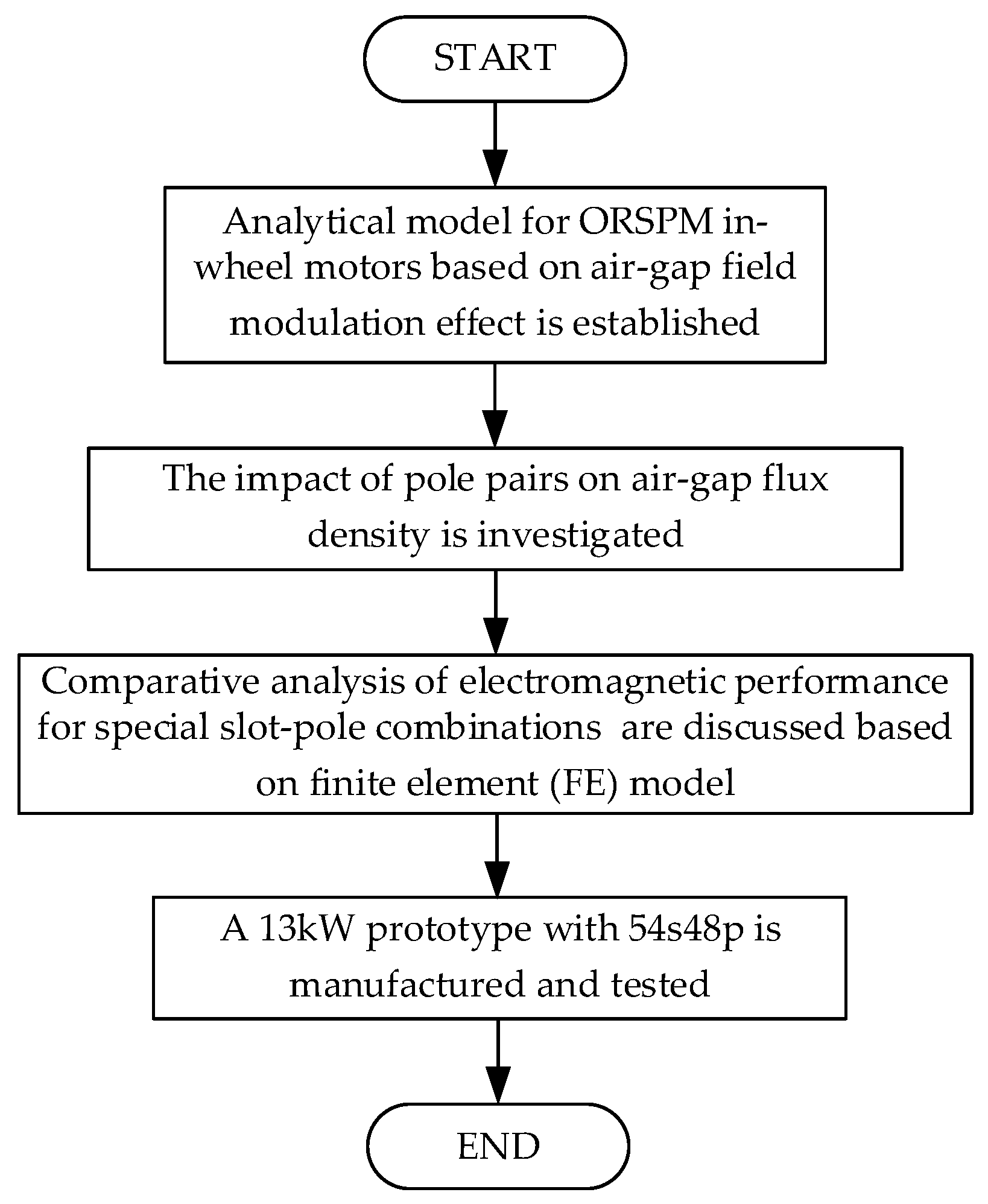
- The analytical model (AM) is established for ORSPM in-wheel motors based on the magnetic field modulation effect.
- (2)
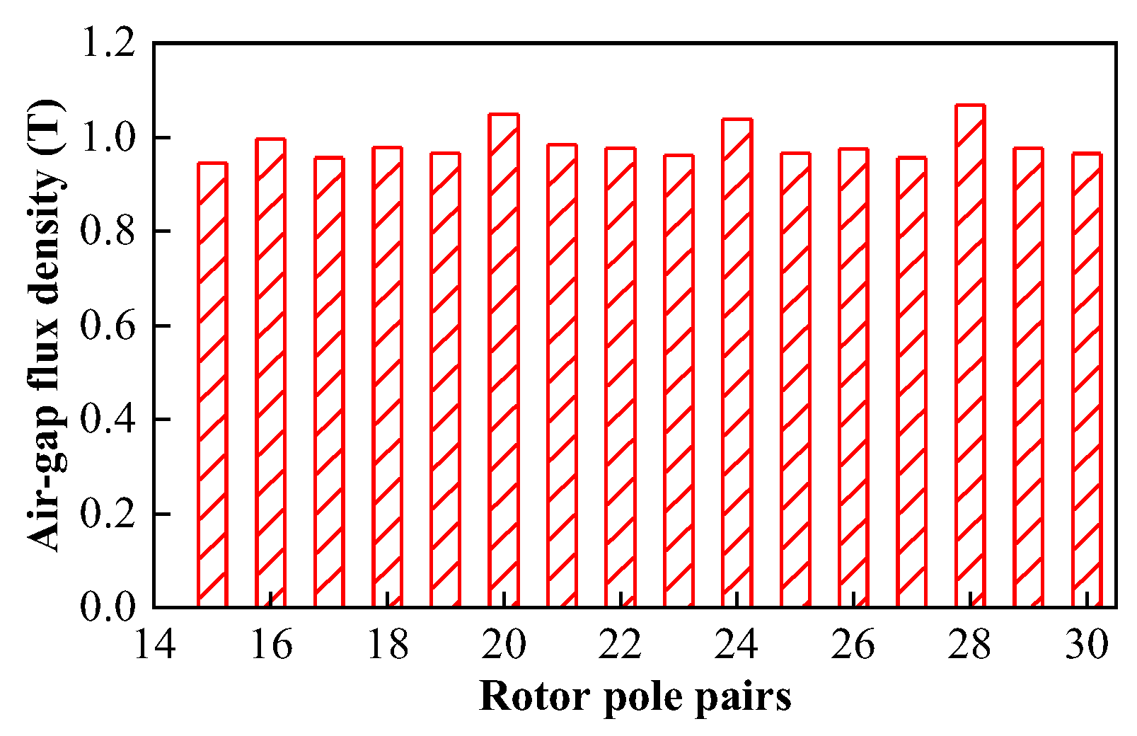
- The relationship between pole pairs and resultant air-gap flux density is investigated and the feasible slot–pole combinations are summarized to improve the flux density.
- (3)
- The ORSPM motors with some special pole–slot combinations are built and compared, which demonstrate that the 54s48p in-wheel motor has superior electromagnetic performance.
2. Methodology and Topologies of the ORSPM Motors
3. Analytical Model and Slot–Pole Combinations of the ORSPM In-Wheel Motor
3.1. PM MMF-Permeance Model
3.2. Feasible Slot–Pole Combinations
4. Performance Evaluation
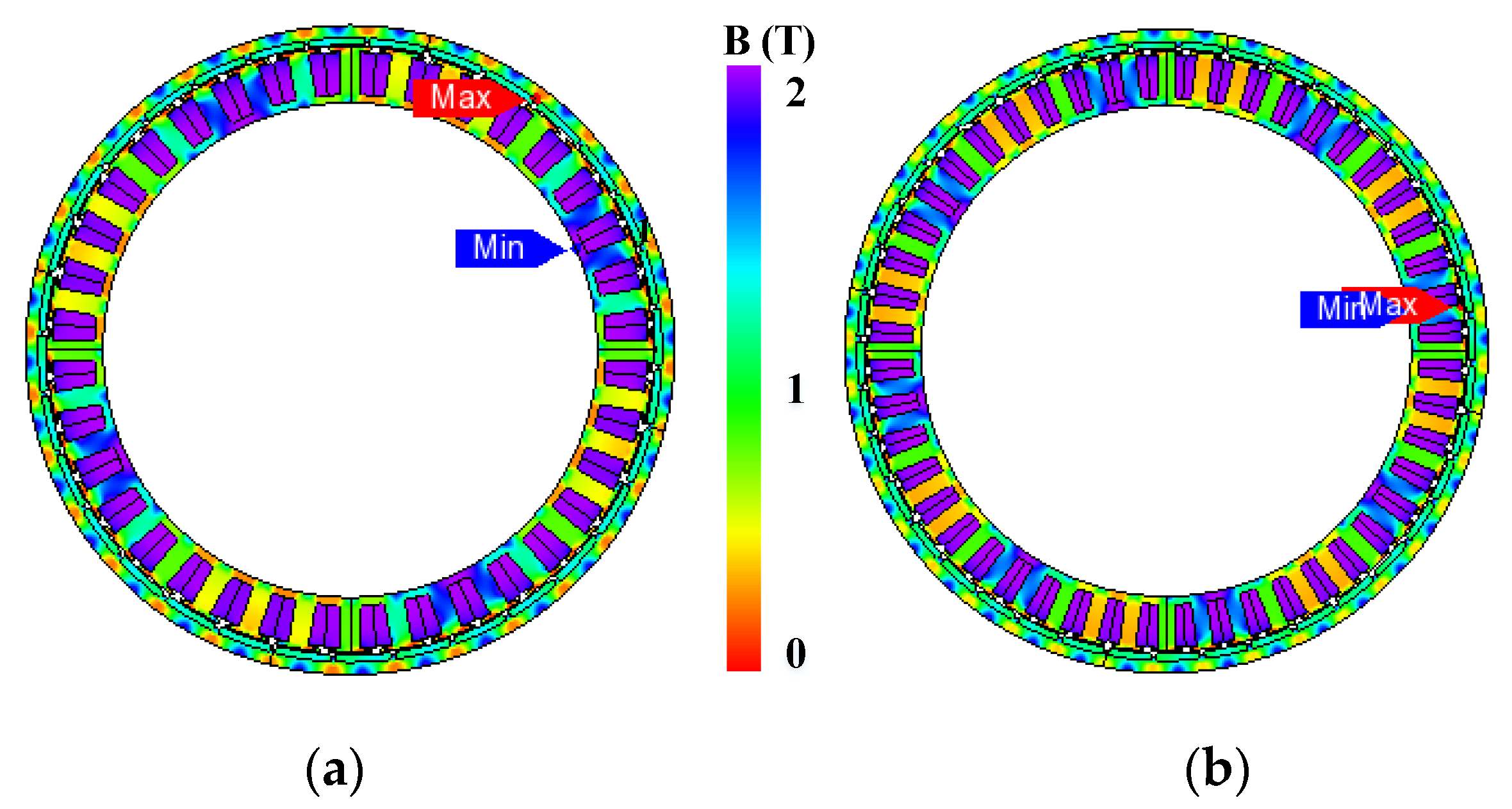
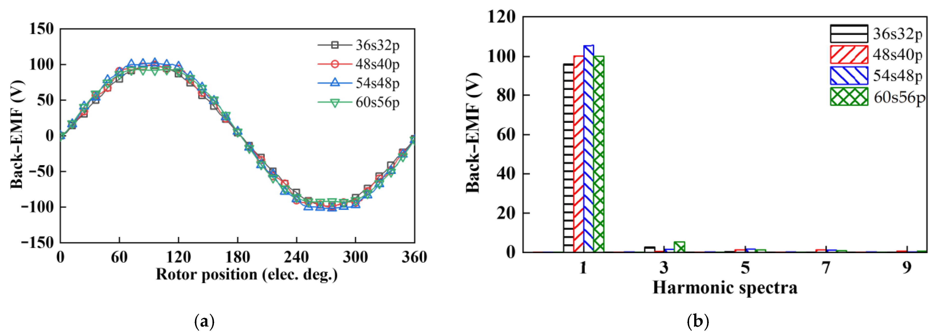
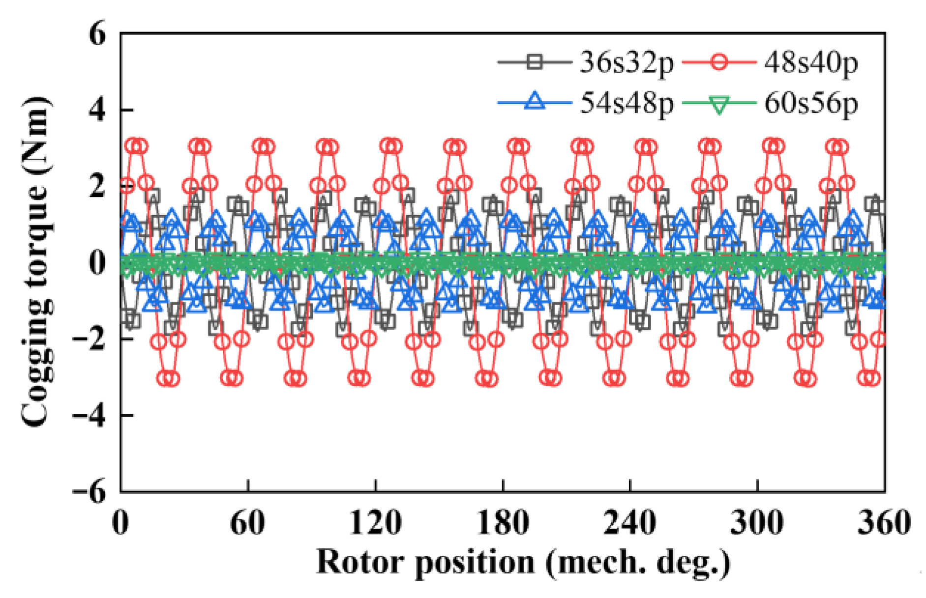
4.1. No-Load Characteristics
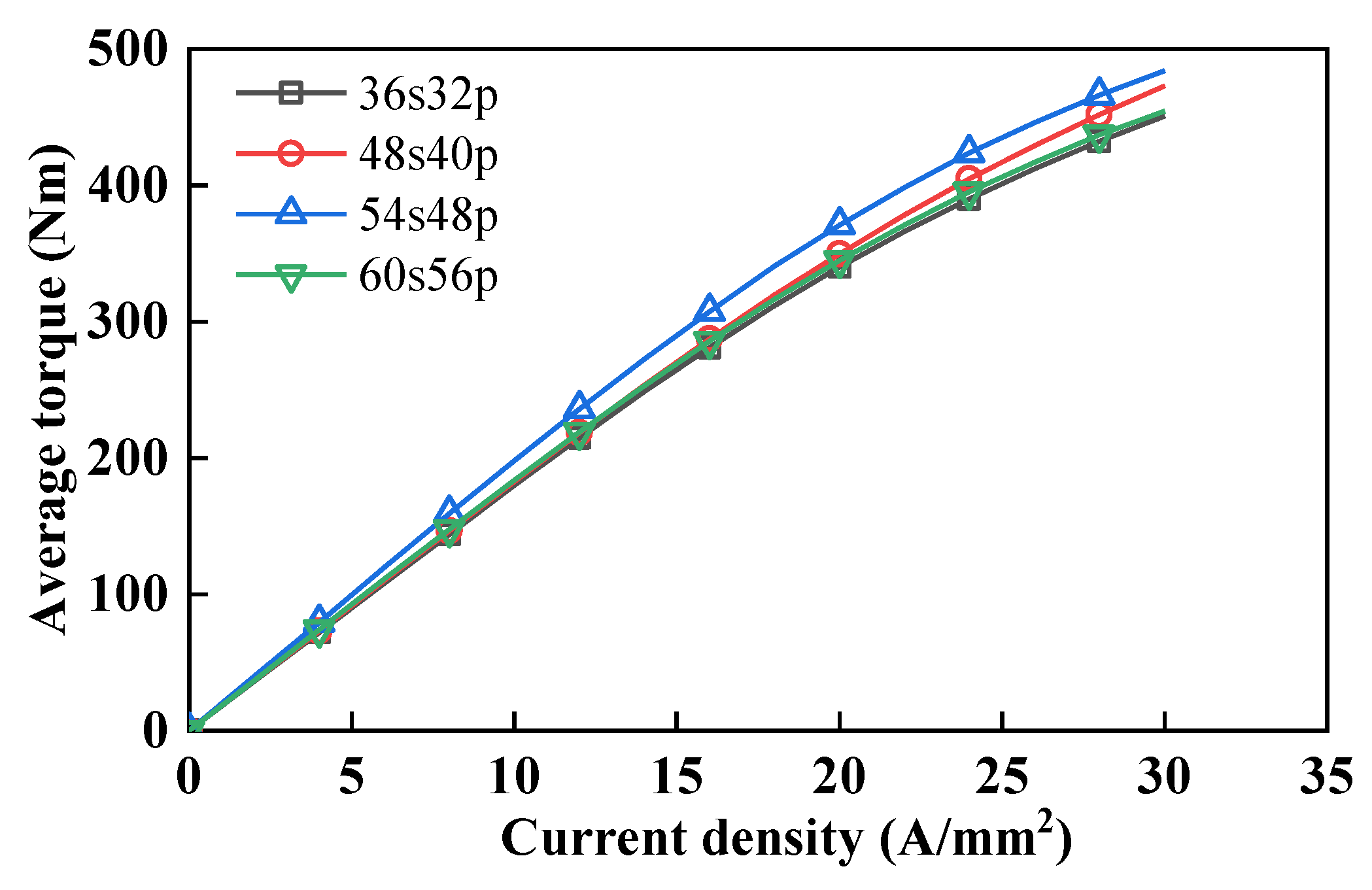
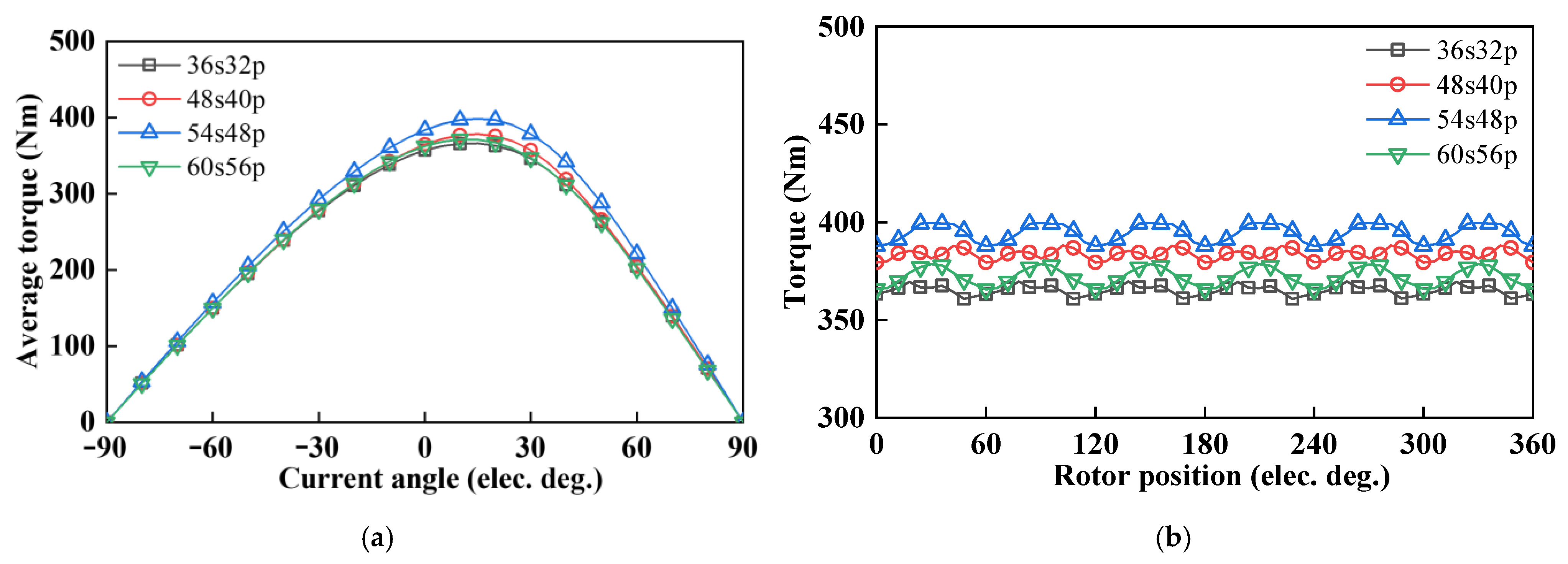
4.2. On-Load Torque
4.3. Field-Weakening Capability and Efficiency
5. Discussion
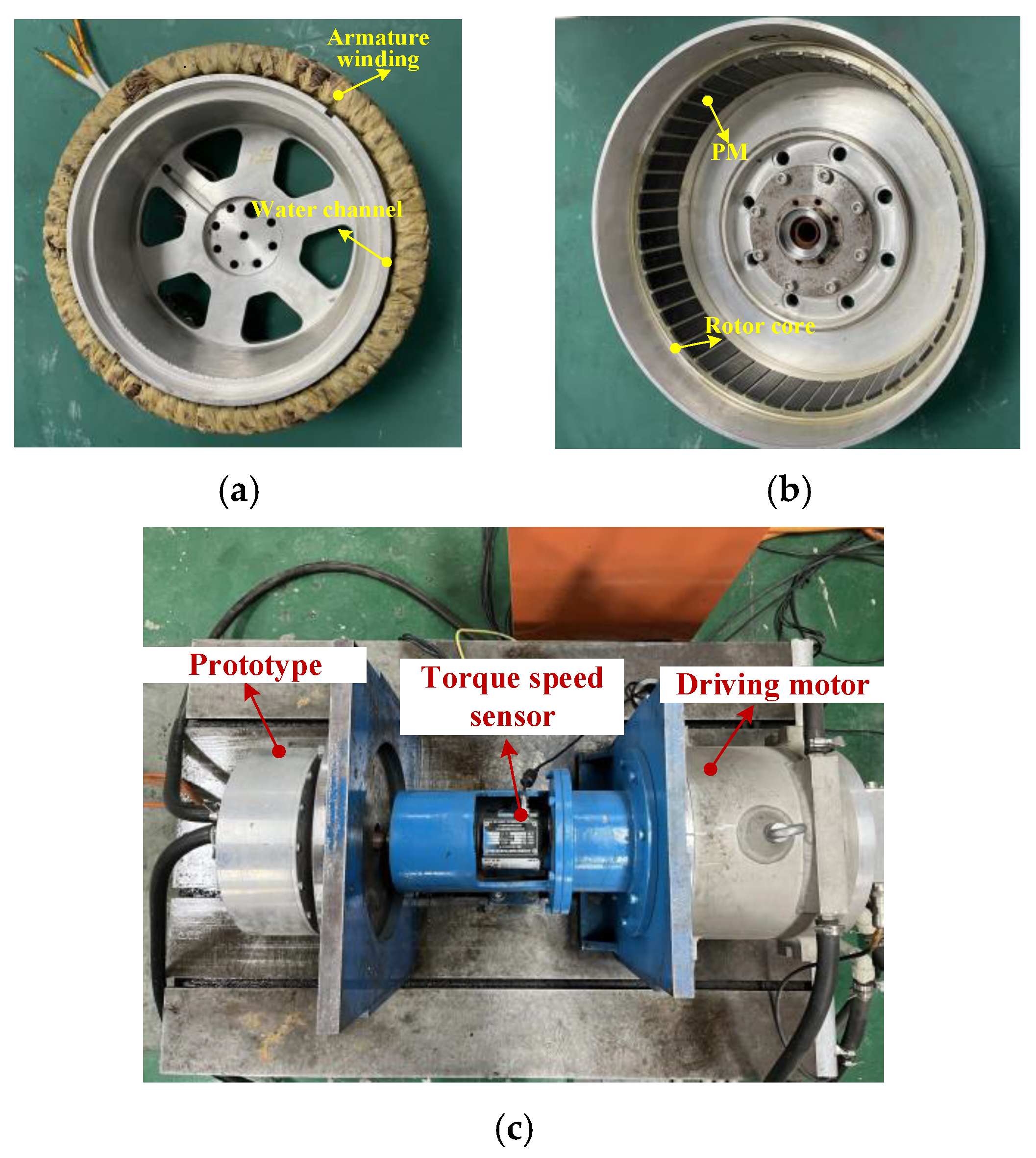
6. Experimental Verification
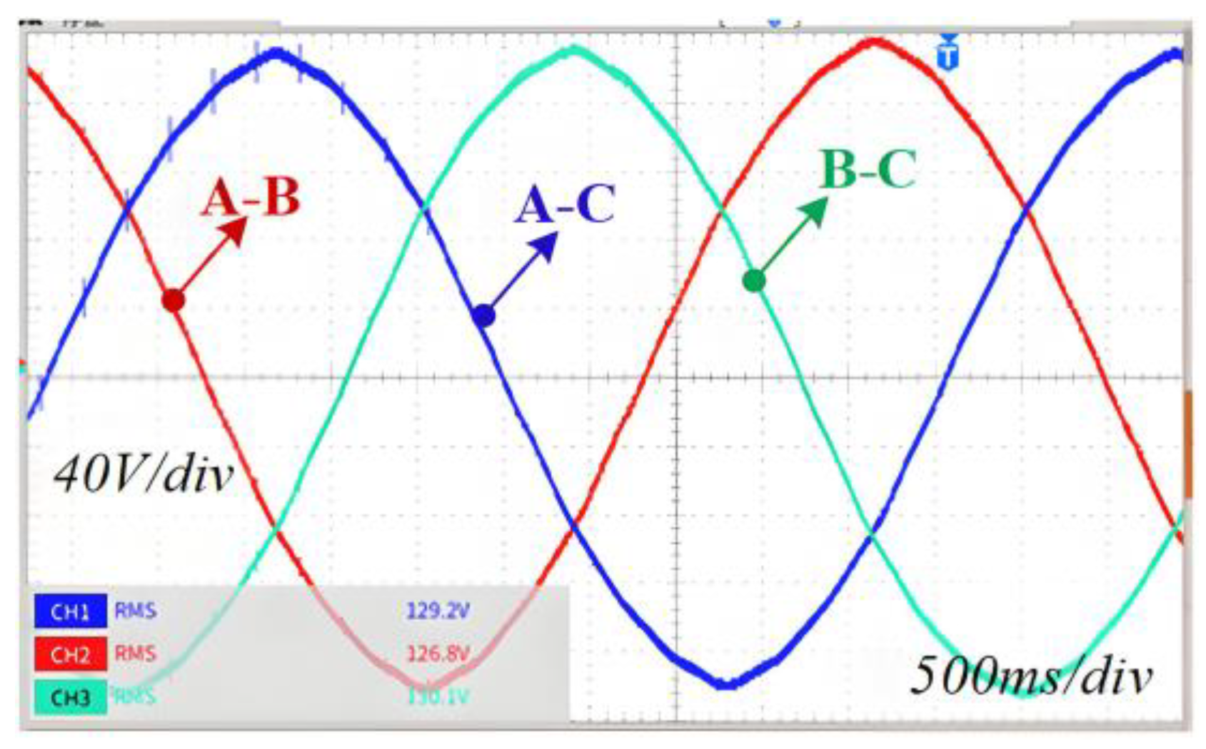
6.1. No-Load Test
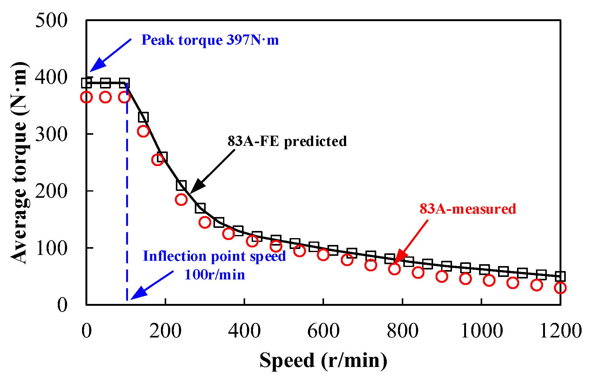
6.2. On-Load Test
7. Conclusions
Funding
Data Availability Statement
Conflicts of Interest
References
- Cai, S.; Kirtley, J.L.; Lee, C.H.T. Critical review of direct-drive electrical machine systems for electric and hybrid electric vehicles. IEEE Trans. Energy Convers. 2022, 37, 2657–2668. [Google Scholar] [CrossRef]
- Cui, S.; Han, S.; Chan, C.C. Overview of multi-machine drive systems for electric and hybrid electric vehicles. In Proceedings of the 2014 IEEE Conference and Expo Transportation Electrification Asia-Pacific (ITEC Asia-Pacific), Beijing, China, 31 August–3 September 2014; pp. 1–6. [Google Scholar]
- Hori, Y. Future vehicle driven by electricity and Control-research on four-wheel-motored “UOT electric march II”. IEEE Trans. Ind. Electron. 2004, 51, 954–962. [Google Scholar] [CrossRef]
- Wang, X.; Gao, P.; Wang, G. The design of Halbach array permanent magnet for In-wheel motor. In Proceedings of the 2013 International Conference on Electrical Machines and Systems (ICEMS), Busan, Republic of Korea, 26–29 October 2013; IEEE: New York, NY, USA, 2013; pp. 1252–1255. [Google Scholar]
- Terashima, M.; Ashikaga, T.; Mizuno, T.; Natori, K.; Fujiwara, N.; Yada, M. Novel motors and controllers for high-performance electric vehicle with four in-wheel motors. IEEE Trans. Ind. Electron. 1997, 44, 28–38. [Google Scholar] [CrossRef]
- Khatab, M.F.H.; Zhu, Z.Q.; Li, H.Y.; Liu, Y. Comparative study of novel axial flux magnetically geared and conventional axial flux permanent magnet machines. CES Trans. Electr. Mach. Syst. 2018, 2, 392–398. [Google Scholar] [CrossRef]
- Fodorean, D.; Idoumghar, L.; Brévilliers, M.; Minciunescu, P.; Irimia, C. Hybrid differential evolution algorithm employed for the optimum design of a high-speed PMSM used for EV propulsion. IEEE Trans. Ind. Electron. 2017, 64, 9824–9833. [Google Scholar] [CrossRef]
- Toulabi, M.S.; Salmon, J.; Knight, A.M. Concentrated winding IPM synchronous motor design for wide field weakening applications. IEEE Trans. Ind. Appl. 2017, 53, 1892–1900. [Google Scholar] [CrossRef]
- Fang, X.; Zhang, B.; Qu, R. Comparative thermal analysis of IPMSMs with integral-slot distributed-winding (ISDW) and fractional-slot concentrated-winding (FSCW) for electric vehicle application. IEEE Trans. Ind. Appl. 2019, 55, 3577–3588. [Google Scholar]
- El-Refaie, A.; Osama, M. High specific power electrical machines: A system perspective. In Proceedings of the 2017 20th International Conference on Electrical Machines and Systems (ICEMS), Sydney, Australia, 11–14 August 2017; pp. 1–6. [Google Scholar]
- Wang, R.; Chen, Y.; Feng, D.; Huang, X.; Wang, J. Development and performance characterization of an electric ground vehicle with independently actuated in-wheel motors. J. Power Sources 2011, 196, 3962–3971. [Google Scholar] [CrossRef]
- Galea, M.; Hamiti, T.; Gerada, C. Torque density improvements for high performance machines. In Proceedings of the IEEE Electric Machines & Drives Conference, Chicago, IL, USA, 12–15 May 2013. [Google Scholar]
- Chen, Y.; Wang, J. Design and evaluation on electric differentials for overactuated electric ground vehicles with four independent in-wheel motors. IEEE Trans. Veh. Technol. 2012, 61, 1534–1542. [Google Scholar] [CrossRef]
- Wang, J.; Atallah, K.; Zhu, Z.Q.; Howe, D. Modular three-phase permanent magnet brushless machines for in-wheel applications. IEEE Trans. Veh. Technol. 2008, 57, 2714–2720. [Google Scholar] [CrossRef]
- Deepak, K.; Frikha, M.A.; Benômar, Y.; El Baghdadi, M.; Hegazy, O. In-wheel motor drive systems for electric vehicles: State of the art, challenges, and future trends. Energies 2023, 16, 3121. [Google Scholar] [CrossRef]
- Chung, S.U.; Moon, S.H.; Kim, D.J.; Kim, J.M. Development of a 20-pole–24-slot SPMSM with consequent pole rotor for in-wheel direct drive. IEEE Trans. Ind. Electron. 2016, 63, 302–309. [Google Scholar] [CrossRef]
- Ifedi, C.J.; Mecrow, B.C.; Brockway, S.T.M.; Boast, G.S.; Atkinson, G.J.; Perovic, D.K. Fault-tolerant in-wheel motor topologies for high performance electric vehicles. IEEE Trans. Ind. Appl. 2013, 49, 1249–1257. [Google Scholar] [CrossRef]
- Chau, K.T.; Chan, C.C.; Liu, C. Overview of permanent-magnet brushless drives for electric and hybrid electric vehicles. IEEE Trans. Ind. Electron. 2008, 55, 2246–2257. [Google Scholar] [CrossRef]
- Zhang, H.L.; Hua, W.; Wu, Z.Z. Modular spoke-type permanent-magnet machine for in-wheel traction applications. IEEE Trans. Ind. Electron. 2018, 65, 7648–7659. [Google Scholar] [CrossRef]
- Hua, W.; Zhang, H.L.; Cheng, M.; Meng, J.J.; Hou, C. An outer-rotor flux-switching permanent-magnet-machine with wedge-shaped magnets for in-wheel light traction. IEEE Trans. Ind. Electron. 2017, 64, 69–80. [Google Scholar] [CrossRef]
- Zhang, H.L.; Hua, W. A novel outer-rotor-permanent-magnet flux-switching machine for in-wheel light traction. In Proceedings of the IECON 2016—42nd Annual Conference of the IEEE Industrial Electronics Society, Florence, Italy, 23–26 October 2016; pp. 6633–6638. [Google Scholar]
- Xu, Z.; Cheng, M. Design and performance characterization of the E-Core outer-rotor hybrid-excitation flux switching machine. Energies 2025, 18, 629. [Google Scholar] [CrossRef]
- Gong, J.; Zhao, B.; Huang, Y.; Semail, E.; Nguyen, N.K. Quantitative comparisons of outer-rotor permanent magnet machines of different structures/phases for in-wheel electrical vehicle application. Energies 2022, 15, 6688. [Google Scholar] [CrossRef]
- Bi, Y.; Fu, W.; Niu, S.; Huang, J. Comparative analysis of consequent-pole flux-switching machines with different permanent magnet arrangements for outer-rotor in-wheel direct-drive applications. Energies 2023, 16, 6650. [Google Scholar] [CrossRef]
- Yazdan, T.; Kwon, B.-I. Electromagnetic design and performance analysis of a two-phase AFPM BLDC motor for the only-pull drive technique. IET Electr. Power Appl. 2018, 12, 999–1005. [Google Scholar] [CrossRef]
- Taran, N.; Rallabandi, V.; Heins, G.; Ionel, D.M. Coreless and conventional axial flux permanent magnet motors for solar cars. IEEE Trans. Ind. Appl. 2018, 54, 5907–5917. [Google Scholar] [CrossRef]
- Yang, Y.P.; Chuang, D.S. Optimal Design and Control of a Wheel Motor for Electric Passenger Cars. IEEE Trans. Magn. 2006, 45, 51–61. [Google Scholar]
- Ho, S.L.; Niu, S.; Fu, W.N. Design and Analysis of a Novel Axial-Flux Electric Machine. IEEE Trans. Magn. 2011, 47, 4368–4371. [Google Scholar] [CrossRef]
- Zhu, Z.Q.; Howe, D. Instantaneous magnetic field distribution in brushless permanent magnetic DC motors, Part III: Effect of stator slot ting. IEEE Trans. Magn. 1993, 29, 8103904. [Google Scholar]
- Geng, W.; Wang, Y.; Wang, J.; Hou, J.; Guo, J.; Zhang, Z. Comparative study of yokeless stator axial-flux PM machines having fractional slot concentrated and integral slot distributed windings for electric vehicle traction applications. IEEE Trans. Ind. Electron. 2022, 70, 155–166. [Google Scholar] [CrossRef]
- Wang, Q.; Wang, C.; Li, Y. Performance evaluating of rotor arrangement on high torque density in-wheel permanent magnet machines. IET Electr. Power Appl. 2023, 17, 813–823. [Google Scholar] [CrossRef]
- Xu, H.; Wang, C. Multi-objective optimization of high torque density spoke-type PM machine for special vehicle drive system. COMPEL Int. J. Comput. Math. Electr. Electron. Eng. 2022, 42, 637–654. [Google Scholar] [CrossRef]


| Items | ORSPM Motors | |||
|---|---|---|---|---|
| Stator slots | 36 | 48 | 54 | 60 |
| Rotor poles | 32 | 40 | 48 | 56 |
| Rotor outer radius, mm | 157.5 | |||
| Stator outer radius, mm | 147.0 | |||
| Rotor inner radius, mm | 148.0 | |||
| Stator inner radius, mm | 120 | |||
| Air-gap length, mm | 1.0 | |||
| PM thickness, mm | 4.0 | |||
| Active stack length, mm | 48 | |||
| Peak current, A | 83 | |||
| PM grade | 30UH | |||
| Steel grade | BAT1500 | |||
| Stator-Pole Combinations | 36s32p | 48s40p | 54s48p | 60s56p |
|---|---|---|---|---|
| Ld, (mH) | 0.64 | 0.40 | 0.43 | 0.41 |
| Lq, (mH) | 0.89 | 0.67 | 0.65 | 0.58 |
| Topology | Contribution Comparison |
|---|---|
| ORSPM in-wheel motor | Investigating the relationship between pole pairs and resultant air-gap flux density and the ORSPM motors with some special pole–slot combinations are built and compared, which demonstrate the 54s48p in-wheel motor has superior electromagnetic performance. |
| Internal rotor interior PM motor | The electromagnetic performance is compared and analyzed with other three different types of traditional rotor topologies. |
| Spoke-type PM motor | The respond surface (RS) method and black-hole (BH) algorithm are used to enhance the efficiencies of multi-objective optimization processes. |
| Outer-rotor PM motor | The comparative analysis of different outer-rotor PM motors designed for in-wheel EV which demonstrates that multi-phase motors exhibit superior electromagnetic properties. |
| Axial flux PM (AFPM) motor | The AFPM motor is investigated due to its superior torque density characteristics compared with radial flux PM motors. |
| Parameter | 36s32p | 48s40p | 54s48p | 60s56p |
|---|---|---|---|---|
| Back-EMF amplitude(V) | 95.5 | 102.5 | 105.6 | 99.8 |
| Cogging peak Torque(Nm) | 1.6 | 3.6 | 1.1 | 0.35 |
| Average torque(Nm) | 362.5 | 385.6 | 396.5 | 370.3 |
| Maximum efficiency | 96.13% | 95.94% | 95.95% | 95.85 |
| Parameter | FE-Predicted | Tested |
|---|---|---|
| Back-EMF coefficient | 0.3275 | 0.3225 |
| Phase resistance (at 20 °C) | 0.046 Ω | 0.044 Ω |
| d-axis inductance | 0.434 mH | 0.431 mH |
| q-axis inductance | 0.655 mH | 0.653 mH |
Disclaimer/Publisher’s Note: The statements, opinions and data contained in all publications are solely those of the individual author(s) and contributor(s) and not of MDPI and/or the editor(s). MDPI and/or the editor(s) disclaim responsibility for any injury to people or property resulting from any ideas, methods, instructions or products referred to in the content. |
© 2025 by the author. Published by MDPI on behalf of the World Electric Vehicle Association. Licensee MDPI, Basel, Switzerland. This article is an open access article distributed under the terms and conditions of the Creative Commons Attribution (CC BY) license (https://creativecommons.org/licenses/by/4.0/).
Share and Cite
Wang, Q. Performance Evaluation of Outer Rotor Permanent Magnet Direct Drive In-Wheel Motor Based on Air-Gap Field Modulation Effect. World Electr. Veh. J. 2025, 16, 247. https://doi.org/10.3390/wevj16050247
Wang Q. Performance Evaluation of Outer Rotor Permanent Magnet Direct Drive In-Wheel Motor Based on Air-Gap Field Modulation Effect. World Electric Vehicle Journal. 2025; 16(5):247. https://doi.org/10.3390/wevj16050247
Chicago/Turabian StyleWang, Qin. 2025. "Performance Evaluation of Outer Rotor Permanent Magnet Direct Drive In-Wheel Motor Based on Air-Gap Field Modulation Effect" World Electric Vehicle Journal 16, no. 5: 247. https://doi.org/10.3390/wevj16050247
APA StyleWang, Q. (2025). Performance Evaluation of Outer Rotor Permanent Magnet Direct Drive In-Wheel Motor Based on Air-Gap Field Modulation Effect. World Electric Vehicle Journal, 16(5), 247. https://doi.org/10.3390/wevj16050247