Article

Research on Unbalanced Electromagnetic Force Under Static Eccentricity of the Wheel Hub Motor Based on BP Neural Network

1
Automotive Engineering Research Institute, Jiangsu University, Zhenjiang 212013, China
2
School of Automotive and Traffic Engineering, Jiangsu University, Zhenjiang 212013, China
*
Author to whom correspondence should be addressed.
World Electr. Veh. J. 2025, 16(5), 252; https://doi.org/10.3390/wevj16050252
Submission received: 31 March 2025 / Revised: 22 April 2025 / Accepted: 27 April 2025 / Published: 28 April 2025

Abstract

:
Aiming at exploring a high-precision unbalanced electromagnetic force model suitable for the dynamic simulation of wheel hub direct-drive electric vehicles, this article establishes the unbalanced electromagnetic force model under static eccentricity of a wheel hub motor by an analytical method and verifies its accuracy by finite element modeling. Then, it optimizes the unbalanced electromagnetic force model based on a BP neural network and couples it with the 1/2 vehicle vertical vibration model to improve its calculation and operation efficiency. Finally, the correctness of the coupling model is further verified by bench experiments. The results show that the analytical model of the unbalanced electromagnetic force is accurate. A BP neural network optimization algorithm can reduce the time of electromagnetic force model simulation for 10 s from 1 h to about 50 s, which greatly improves the calculation efficiency of the electromagnetic force on the basis of ensuring the accuracy of the model, thus providing an unbalanced electromagnetic force model that is more suitable for the dynamic simulation of wheel hub direct-drive electric vehicles, which effectively solves the problem that the traditional electromagnetic force is difficult to couple with the vehicle dynamics model and lays a better foundation for subsequent research on the vertical vibration effect of wheel hub direct-drive electric vehicles.

1. Introduction

Wheel hub direct-drive electric vehicles have been widely studied in recent years due to their advantages, such as low vehicle mass, high transmission efficiency, flexible driving modes, and space-saving [1,2,3]. However, in addition to the increase in unsprung mass due to the introduction of the motor, automobile production and assembly problems will cause eccentricity of the fixed rotor of the motor [4,5], and the effect of road excitation in the running of the vehicle will aggravate this eccentricity, and then produce vertical unbalanced electromagnetic force acting on the motor, causing the motor vibration to intensify, and further deteriorate the riding comfort and driving safety of the vehicle [6,7,8,9]. Such a vicious cycle leads to the problem of the negative effect of vertical vibration on wheel hub direct-drive electric vehicles. Therefore, in order to study the negative vertical vibration effect of wheel hub direct-drive electric vehicles under the dual excitation composed of road surface and unbalanced electromagnetic force and provide subsidies for future control strategies in further research, the establishment of wheel hub motor air gap magnetic field and unbalanced electromagnetic force model has become a prerequisite that cannot be ignored, and scholars at home and abroad have carried out corresponding research.
At present, there are two methods to solve the air gap magnetic field and electromagnetic force of the wheel hub motor: the finite element method and the analytical method. Compared with the finite element method, which can obtain the exact solution of the air gap magnetic field by establishing the finite element model considering the structure and material characteristics of the motor, the analytical method is more convenient to calculate the air gap magnetic field of the motor and explore the change law of the electromagnetic force. This method was first proposed by Professor Zhu of the University of Sheffield, UK [10,11,12,13]. Compared with the finite element calculation results, the obtained air gap magnetic field had high calculation accuracy. Scholars widely adopted it in subsequent research on the air gap magnetic field and electromagnetic force of wheel hub motors. Sun et al. [14] selected a four-phase switched reluctance motor and used an analytical method to calculate and analyze the unbalanced electromagnetic force. Ma et al. [15,16] obtained the air gap magnetic field analytical model of a permanent magnet brushless DC motor without considering the slot by solving the Poisson equation. Zhang [17,18] and Du et al. [19] established the air gap magnetic field model of a permanent magnet motor by using the multi-layer model method. Chen et al. [20] solved the unbalanced electromagnetic force of a permanent magnet synchronous motor when it is eccentric and verified that it is the main reason for aggravating motor vibration. Yang et al. [21] obtained the unbalanced electromagnetic force model by solving the air gap magnetic field equation and verified its accuracy based on the finite element method. Deng et al. [22] established and analyzed the unbalanced electromagnetic force model generated by the eccentricity of the motor, suppressed its amplitude and fluctuation, and finally alleviated the vertical dynamic negative effect of the vehicles. Li et al. [23] of Jiangsu University established the unbalanced electromagnetic force model of a permanent magnet motor under static eccentricity by the analytical method. Aiming at the influence of unbalanced electromagnetic force on vehicle dynamic response under motor resonance frequency, semi-active suspension linear quadratic regulation control was proposed to adjust the suspension control force, which finally suppressed the motor’s eccentricity and improved the ride comfort and tire grounding of the vehicle. Li et al. [24] used the composite Cotes method to solve the unbalanced electromagnetic force and verified its accuracy based on the finite element method and bench experiment, respectively. Wu et al. [25] established the unbalanced electromagnetic force model under dynamic eccentricity by the finite element method. They found that motor eccentricity is the main factor affecting the amplitude of the unbalanced electromagnetic force. Li et al. [26,27] obtained the overall vertical force of the motor by summing the vertical force generated by the single-phase rotor.
Based on the above research, most of the current research on the modeling of air gap magnetic field and unbalanced electromagnetic force of wheel hub motor is based on the analytical method or the finite element method. However, although the analytical method can accurately describe the variation characteristics of the unbalanced electromagnetic force, the calculation of the model is time-consuming and laborious, and the accuracy is difficult to guarantee because a lot of integral and summation operations are used in the calculation process. Although the finite element method has high accuracy, it can only solve the unbalanced electromagnetic force under fixed eccentricity, and the eccentricity of the fixed rotor of the motor changes with time during the driving process, which ultimately makes it difficult for both of them to couple the unbalanced electromagnetic force with the vertical dynamics model of the vehicle in real time. It is not conducive to real-time and fast dynamic analysis and control research combined with a vehicle dynamics model. Therefore, it is necessary to improve the existing model and further explore a high-precision unbalanced electromagnetic force model suitable for dynamic simulation.
In order to solve the above problems, an analytical model of the unbalanced electromagnetic force of a permanent magnet synchronous motor is established in this paper, and the calculation accuracy of the model is verified by finite element simulation. On this basis, aiming at the problems of complex calculation and low efficiency of the existing analytical model, the wheel hub electromagnetic force calculation model based on the BP neural network is further constructed, and it couples with the 1/2 vehicle dynamics model, which greatly improves the calculation efficiency of the model on the premise of ensuring the calculation accuracy. Finally, an experimental bench is set up to verify the accuracy of the wheel hub motor model and the coupling model of electromagnetic force and vehicle dynamics by collecting single-phase current and stator vertical acceleration, demonstrating that the unbalanced electromagnetic force model optimized by the BP neural network can accurately couple with the vehicle dynamics model. The main contributions of this paper are as follows:
(1)
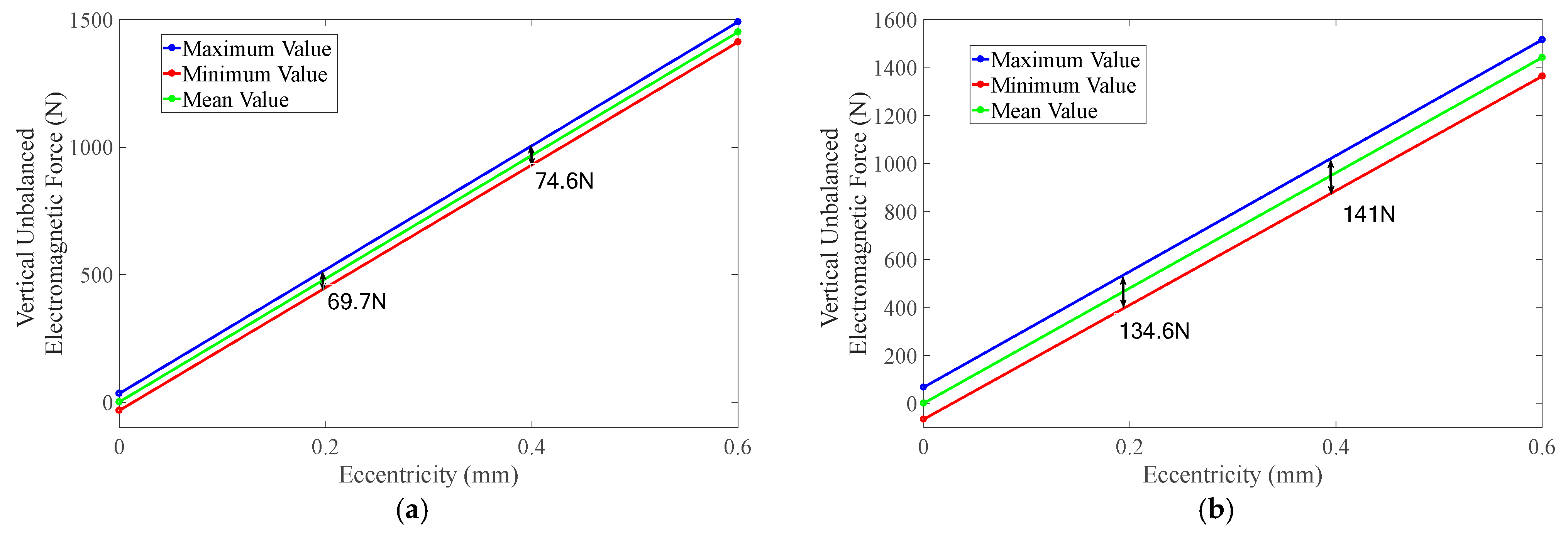
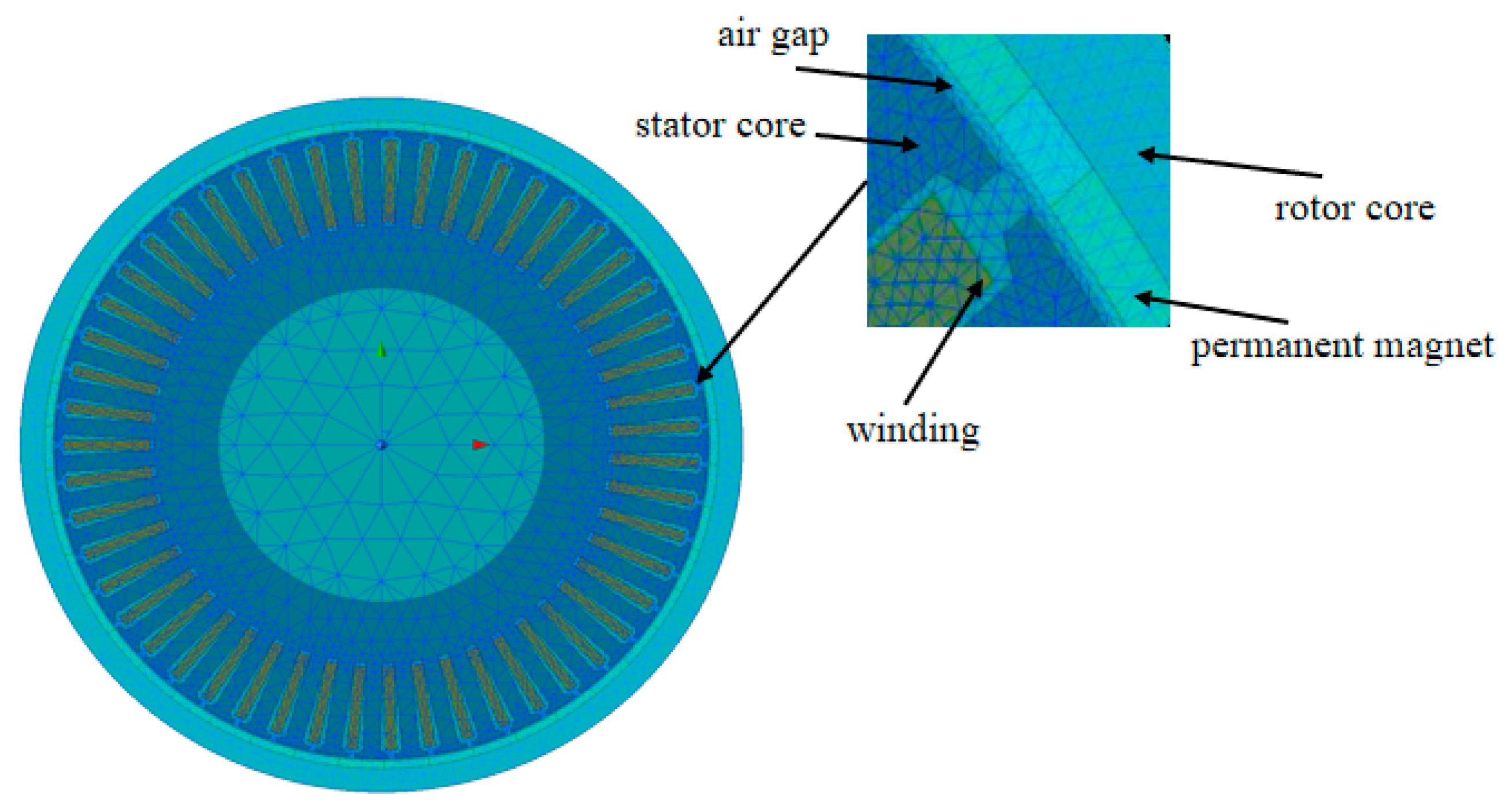
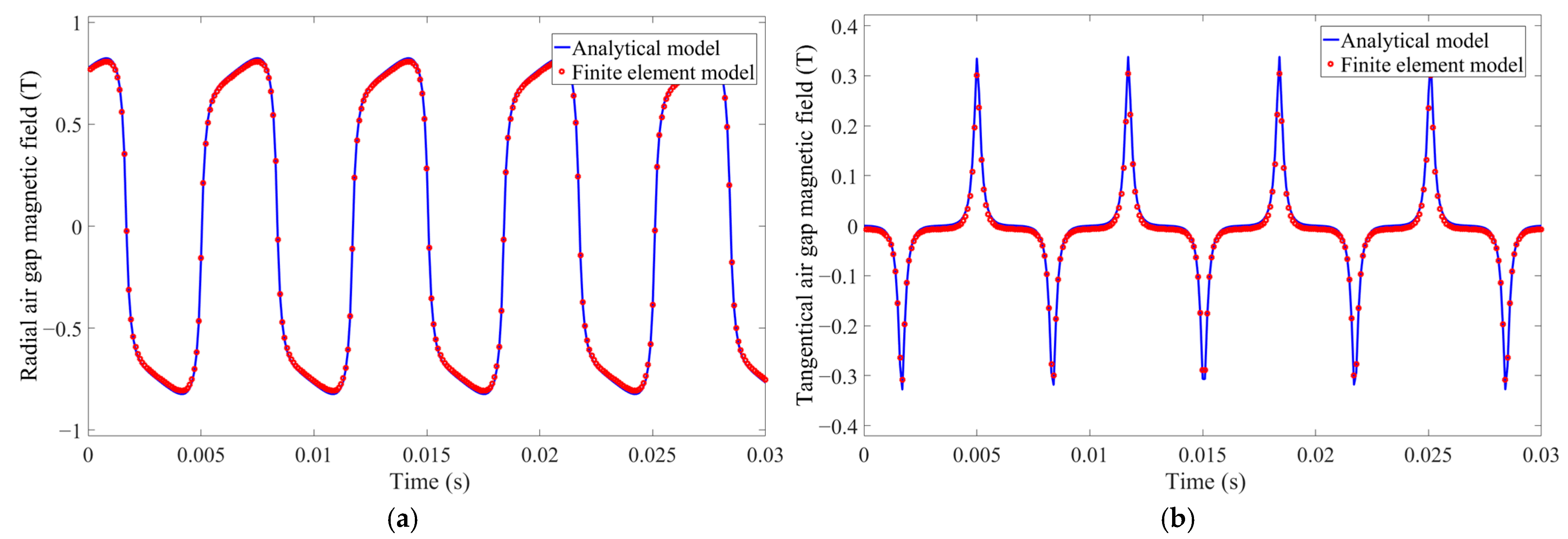
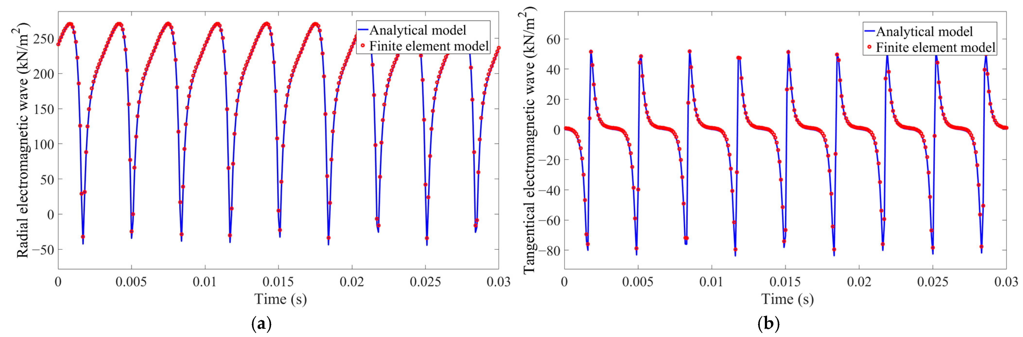
The analytical model of the unbalanced electromagnetic force of a wheel hub motor is constructed, and its accuracy is verified by finite element modeling of the wheel hub motor. The factors affecting the output characteristics of unbalanced electromagnetic force are discussed, which provides a theoretical basis for the subsequent optimization of the BP neural network of electromagnetic force.
(2)
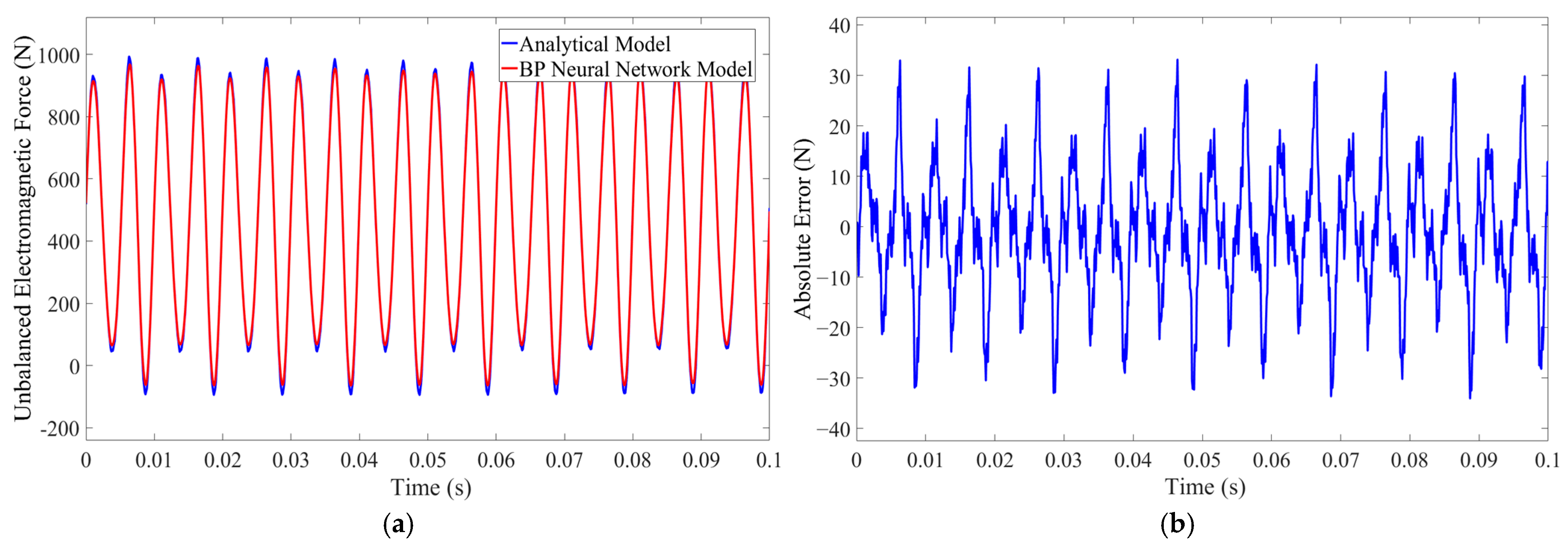
By using the BP neural network to optimize the existing analytical model of unbalanced electromagnetic force, the calculation efficiency of the model is greatly improved on the premise of ensuring the calculation accuracy, thus providing an unbalanced electromagnetic force model that is more suitable for the dynamic simulation of wheel hub direct-drive electric vehicles.
(3)
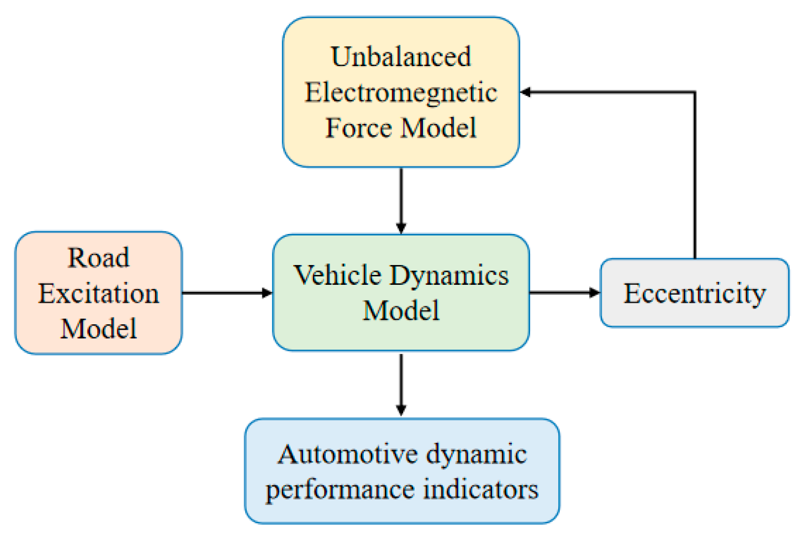
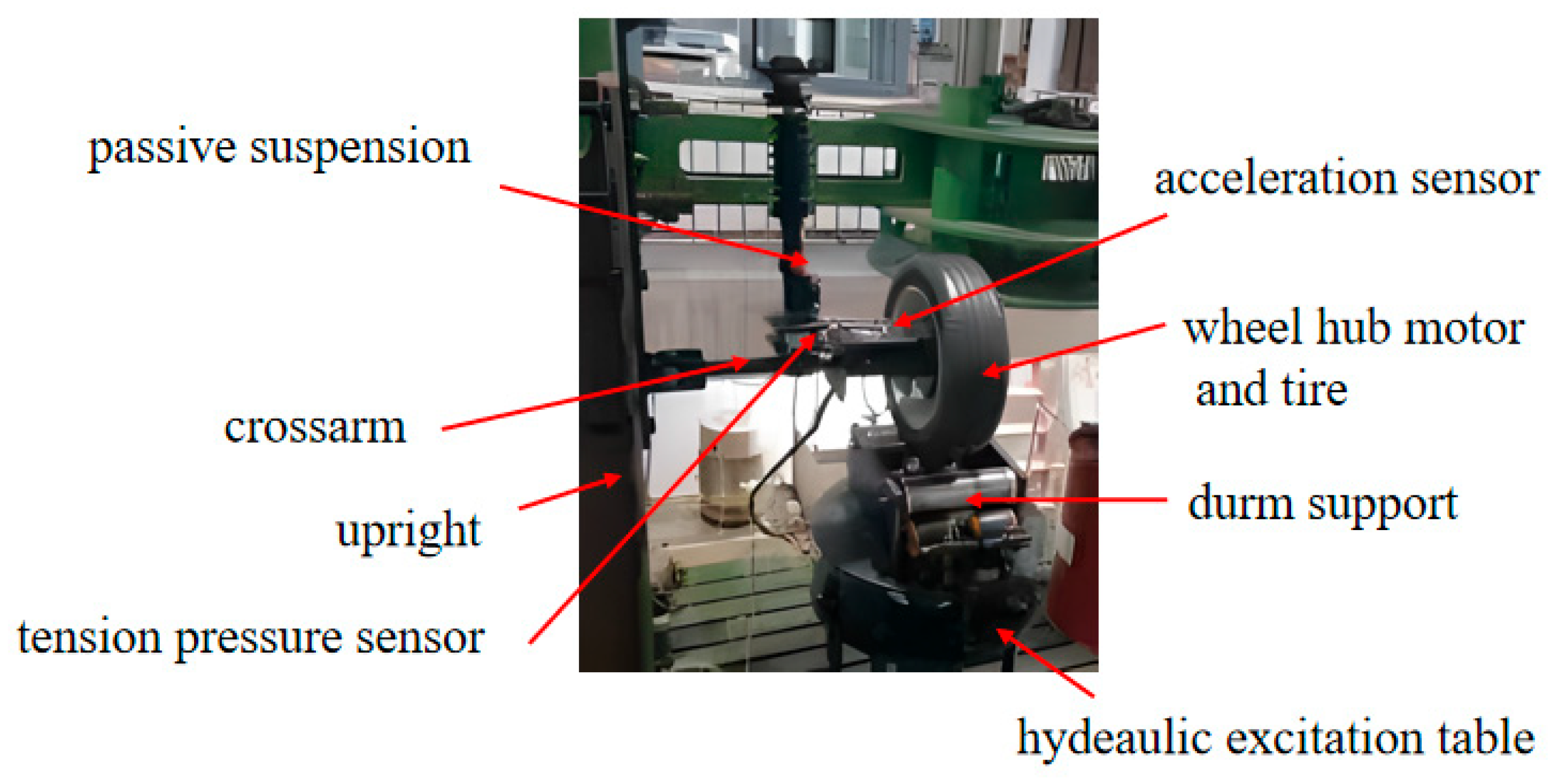
Considering that the unbalanced electromagnetic force is difficult to measure directly through the test, it couples with the vehicle dynamics model, and the correctness of the coupling model is verified by building a test bench, which lays a better foundation for the subsequent research on the vertical vibration effect of wheel hub direct-drive electric vehicles.

2. Unbalanced Electromagnetic Force Model of Wheel Hub Motor

2.1. Wheel Hub Motor Model

The wheel hub motor adopts a permanent magnet synchronous motor with a light weight, small volume, simple structure, and flexible shape and size. In order to facilitate modeling, the following assumptions are made: (1) Ignoring the saturation of the core. (2) Ignoring eddy current and hysteresis losses. (3) The electrical conductivity of the permanent magnetic material is 0, and there is no damping winding on the rotor. (4) The current in the motor is a symmetrical three-phase sinusoidal current, and both the excitation magnetic field generated by the permanent magnets and the armature reaction magnetic field produced by the three-phase windings are sinusoidal waves [28]. Compared with traditional vector control, the non-beat current predictive control with better dynamic performance and smaller harmonic current is adopted for motor control. The voltage equation at moment k is shown in Equation (1) [29].
u d k u q k = G 1 i d k + 1 i q k + 1 F k i d k i q k M k ; F k = 1 T s R L T s ω e k T s ω e k 1 T s R L ;   G = T s L 0 0 T s L ;   M k = 0 T s ψ f L ω e k
where, i d k + 1 and i q k + 1 are the predicted currents at k+1 time (A). u d k and u q k are the output voltages of the d and q axes at time k (V). i d k and i q k are the d and q axis currents sampled at time k (A). ω e k is the electromechanical angular velocity at time k (rad/s). L is the model inductance of the motor (H). ψ f is the model flux linkage of the motor (Wb). R is the model resistance of the motor ( Ω ). Through the three-phase current output of the wheel hub motor model, a foundation can be laid for the subsequent modeling of unbalanced electromagnetic force. The nominal parameters of the wheel hub motor in this study are shown in Table 1.

2.2. Calculation of Air Gap Magnetic Field of Wheel Hub Motor Without Eccentricity

In order to construct the unbalanced electromagnetic force model without eccentricity, it is necessary to establish the air gap magnetic field model without eccentricity, including the radial permanent magnet magnetic field, the tangential permanent magnet magnetic field, the radial armature reaction magnetic field, and the tangential armature reaction magnetic field. Finally, the permanent magnet magnetic field and armature reaction magnetic field are synthesized by the vector addition method to form the air gap magnetic field. The analytical formulas for the radial and tangential permanent magnet magnetic field are as follows [16]:
B m t r , α , t = n = 1 , 3 , 5 μ 0 M n μ r n p n p 2 1 × n p + 1 + 2 R m R r n p 1 + n p 1 R m R r 2 n p μ r + 1 μ r 1 R s R r 2 n p μ r 1 μ r R s R m 2 n p R m R r 2 n p ×   r R m n p 1 + R s R m n p 1 R s r n p + 1 cos n p α θ 0 ω r t
B m r r , α , t = n = 1 , 3 , 5 μ 0 M n μ r n p n p 2 1 × n p + 1 + 2 R m R r n p 1 + n p 1 R m R r 2 n p μ r + 1 μ r 1 R s R r 2 n p μ r 1 μ r R s R m 2 n p R m R r 2 n p ×   r R m n p 1 + R s R m n p 1 R s r n p + 1 sin n p α θ 0 ω r t
where, μ r is the relative permeability of the permanent magnet (H/m). p is the number of permanent magnet poles. R m is the radius of the permanent magnet (mm). R r is the inner diameter of the rotor core (mm). R s is the outer diameter of the stator core (mm). θ 0 is the Angle between the pole center of the rotor at the initial time N and the stator stationary coordinate system x axis (rad). ω r is the motor speed (rpm). M n is the magnetization [16].
The armature reaction magnetic field generated by A, B, and C three-phase winding is synthesized by vector addition. The diagram of a three-phase armature winding is shown in Figure 1. The positive direction of the armature reaction magnetic field is uppercase letters, and the negative direction is lowercase letters.
Taking phase A winding as an example, the pitch of the concentrated winding is one, and its symbol and Angle vector can be obtained from Figure 1 as follows [16]:
s A i = + 1 , 1 , 1 , + 1 , 1 , + 1 , 1 , + 1 , 1 , + 1 , 1 , + 1 , 1 , + 1 , 1 , + 1 , 1
α A i = 1 , 2 , 9 , 10 , 11 , 12 , 20 , 21 , 22 , 30 , 31 , 32 , 40 , 41 , 42 , 50 , 51
Then, the radial and tangential armature reaction magnetic field expressions of the A-phase winding are as follows:
B a r A r , α , t = k = 1 B k r I a t i = 1 N s A i cos k α 2 π Q s α A i 1
B a t A r , α , t = k = 1 B k t I a t i = 1 N s A i sin k α 2 π Q s α A i 1
where,
B k r = 4 μ 0 R s N s π a b 0 r 1 k R s r k r / R r 2 k + 1 R s / R r 2 k 1 sin k α y 2 sin k α 0 2
B k t = 4 μ 0 R s N s π a b 0 r 1 k R s r k r / R r 2 k 1 R s / R r 2 k 1 sin k α y 2 sin k α 0 2
where, I a is A phase winding current (A). N is the number of windings in a series of the A phase. N s is the number of turns per slot of the winding. a is the number of parallel winding branches. b 0 is the width of the slot (mm). α y is the winding pitch of a single motor (rad). α 0 is the notch Angle (rad). r is the radius of the circle at the integration (mm).
Similarly, the analytical formula of the armature reaction magnetic field of the B and C two-phase winding can be obtained. By linear superposition of the three, the analytical formulas of the radial and tangential armature reaction magnetic field are as follows:
B a r r , α , t = k = 1 B k r I a t i = 1 N s A i cos k α 2 π Q s α A i 1 + I b t i = 1 N s B i cos k α 2 π Q s α A i 1 + I c t i = 1 N s C i cos k α 2 π Q s α A i 1
B a t r , α , t = k = 1 B k t I a t i = 1 N s A i sin k α 2 π Q s α A i 1 + I b t i = 1 N s B i sin k α 2 π Q s α A i 1 + I c t i = 1 N s C i sin k α 2 π Q s α A i 1

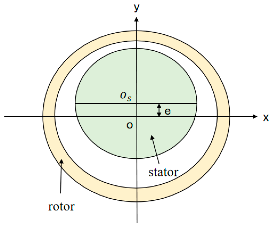
2.3. Calculation of Air Gap Magnetic Field and Unbalanced Electromagnetic Force of Wheel Hub Motor

Assume that the stator is eccentric with the eccentricity of e in the positive direction of the Y-axis, as shown in Figure 2, and o and o s are the rotation centers of the stator and rotor, respectively. In order to accurately analyze the influence caused by eccentricity, many studies transform the air gap magnetic field model without eccentricity into the motor air gap magnetic field model with eccentricity by introducing the permeability correction coefficient [30].
The effective air gap length δ meets δ = δ 0 + h m / μ r , where δ 0 is the actual air gap length (mm). h m is the thickness of the permanent magnet (mm). The expression of the permeability correction coefficient is ε δ = 1 / 1 ε cos α , where ε is the effective eccentricity, and its calculation formula is ε = e / δ . Then the radial and tangential air gap magnetic field expressions under static eccentricity are as follows [30]:
B e r r , α , t = B r r , α , t ε δ
B e t r , α , t = B t r , α , t ε δ
The radial and tangential electromagnetic force waves are calculated, respectively, which are integrated along the circumferential surface of the air gap [16] and then decomposed into the horizontal and vertical axis directions under the rectangular coordinate system. Finally, the calculation formula of the radial unbalanced electromagnetic force of the wheel hub motor under static eccentricity is obtained as follows [5]:
F e z = L r 2 μ 0 0 2 π B e r r , α , t 2 B e t r , α , t 2 sin α + 2 B e r r , α , t B e t r , α , t cos α d α
where L is the axial length of the wheel hub motor (mm).
At this point, the external rotor permanent magnet synchronous motor system model, air gap magnetic field model, and unbalanced electromagnetic force model have all been established. In order to clarify the specific effects of fixed rotor eccentricity and phase current amplitude on the vertical unbalanced electromagnetic force, the vertical unbalanced electromagnetic force is simulated under different relative eccentricities and phase current amplitudes, and the results are shown in Figure 3 and Figure 4, respectively.
Figure 3 shows the variation in the vertical unbalanced electromagnetic force with eccentricity for the current amplitudes of 20 A and 40 A at 390 rpm at a uniform speed. It can be found that under the input current amplitude of phase 20 A, the amplitude of the vertical unbalanced electromagnetic force increases sharply with the increase in the eccentricity of the fixed rotor. When the eccentricity increases from 0 mm to 0.6 mm, the peak value of the vertical unbalanced electromagnetic force increases by nearly 1500 N; however, when the eccentricity increases from 0.3 mm to 0.4 mm, the amplitude of the vertical unbalanced electromagnetic force increases sharply. The fluctuation range of the vertical unbalanced electromagnetic force, that is, the difference between the maximum value and the minimum value, increased from 69.7 N to 74.6 N, an increase of only 4.9 N. Similar simulation results are obtained with 40 A phase current amplitude input.
Figure 4 shows the variation in the vertical unbalanced electromagnetic force with the amplitude of the phase current for the eccentricities of 0.2 mm and 0.6 mm at 390 rpm at uniform speed. It can be found that with the increase in the amplitude of the phase current, the amplitude of the vertical unbalanced electromagnetic force gradually increases and fluctuates more sharply. With 0.2 mm eccentricity, when the phase current amplitude increases from 20 A to 30 A, the fluctuation range of the vertical unbalanced electromagnetic force increases from 69.7 N to 102.9 N. However, with the increase in phase current amplitude, the average value of vertical unbalanced electromagnetic force shows a decreasing trend, from 10 A to 40 A, the average value decreases by about 5 N. The simulation results at 0.6 mm eccentricity are basically the same, but with the increase in the eccentricity, the mean value of vertical unbalanced electromagnetic force increases slightly with the decreased rate of phase current amplitude.
Combined with the above diagram, it can be concluded that the eccentricity of the fixed rotor and the amplitude of the phase current will have an important effect on the unbalanced electromagnetic force output of the motor. Among them, the eccentricity of the fixed rotor is the key factor affecting the amplitude of the vertical unbalanced electromagnetic force, while the phase current amplitude has little influence on the output average value of the non-vertical balanced electromagnetic force, but it is an important reason for the fluctuation of the unbalanced electromagnetic force, which also provides a theoretical basis for the subsequent construction of BP neural network.

3. Finite Element Verification of Wheel Hub Motor Unbalanced Electromagnetic Force

As the traditional analytical modeling has properly simplified the structure of the wheel hub motor, the unbalanced electromagnetic force model established by the analytical method has difficulties in ensuring accuracy, and the air gap magnetic field and electromagnetic force are difficult to measure directly through experiments. Therefore, in order to verify the correctness of the analytical model of the air gap magnetic field and unbalanced electromagnetic force, the finite element modeling method of the wheel hub motor can be adopted. Input the relevant structural parameters of the motor into 2023 R1 version of ANSYS Maxwell, considering that the air gap size of the motor is small relative to its overall size, in order to more accurately analyze the air gap magnetic field of the wheel hub motor, it is assumed that the air gap magnetic field of the wheel hub motor is uniformly distributed along the axial direction, and the vacuum material is used to encrypt the motor air gap space by multiple layers. The finite element simulation model of the wheel hub permanent magnet synchronous motor after grid division is shown in Figure 5. Moreover, the simulated air gap magnetic field and electromagnetic force wave curves are compared with the analytical results for verification. Table 2 is the structure parameter table of the wheel hub motor.
When the eccentricity of the fixed rotor of the wheel hub motor is 0.4 mm, the air gap magnetic field and electromagnetic force wave of the two models is calculated at the speed of the 390 rpm motor, as shown in Figure 6 and Figure 7. It can be seen from the figure that no matter the air gap magnetic field and electromagnetic force wave, the analytical and finite element results both show good agreement in waveform shape and amplitude, which proves the accuracy of the analytical model of unbalanced electromagnetic force under static eccentricity of wheel hub motor.

4. Coupling Model of Unbalanced Electromagnetic Force and Vehicle Dynamics

4.1. The Establishment of the Vertical Vehicle Dynamics Model

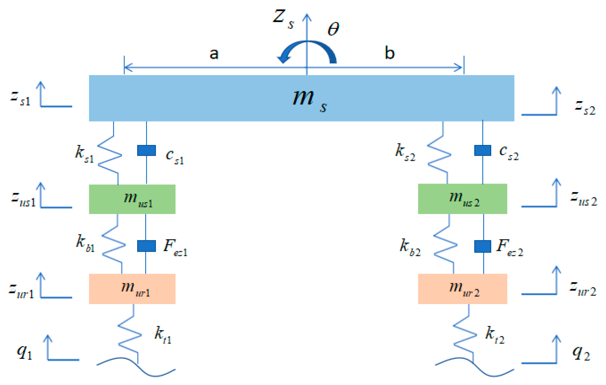
4.1.1. A 1/2 Vertical Vehicle Dynamics Model

In order to couple the unbalanced electromagnetic force with the vehicle dynamics model, the stator and rotor of the motor must be separated during the modeling process, and the air gap of the motor is characterized by the vertical relative displacement between the fixed rotor, that is, the change in the eccentricity of the fixed rotor. Taking the suspension system of 1/4 vehicles as an example, after the introduction of wheel hub motors, it is integrated with the wheel, the rotor part is connected to the wheel, the stator part is connected to the suspension, and the body through the axle, and the stator and the rotor are connected through rigid bearings. The two-mass system of the traditional suspension model is further upgraded to a three-mass system.
As shown in Figure 8, the vehicle dynamics model outputs eccentricity under the excitation of the road surface. The unbalanced electromagnetic force module calculates the unbalanced electromagnetic force based on the output eccentricity and outputs the force to the vehicle dynamics model, further exacerbating the eccentricity. At the same time, it also outputs other vehicle dynamics performance indicators (sprung and unsprung mass acceleration, suspension dynamic deflection, tire dynamic load, etc.). Thus, a coupling between the unbalanced electromagnetic force and the vehicle dynamics model is formed.
Due to technical limitations, wheel hub direct-drive electric vehicles have not yet entered the mass production stage. Therefore, a mini-car developed by the School of Automotive Engineering of our university is taken as the research object, as shown in Figure 9. Assuming that all structural parameters in the model are linear and the body as a whole is rigid, a vertical dynamics model of a half-car is established without considering load transfer. Its structure is shown in Figure 10, and Table 3 is the parameter table of the vertical dynamics model of a semi-car.
The model has six degrees of freedom, among which z u r 1 is the vertical displacement of the front motor rotor and tire, z u s 1 is the vertical displacement of the front motor stator and axle, z u r 2 is the vertical displacement of the rear motor rotor and tire, z u s 2 is the vertical displacement of the rear motor stator and axle, z s is the vertical displacement of the body, θ is the pitch angle of the body, and F e z 1 , F e z 2 are the unbalanced electromagnetic forces generated by the relative eccentricity of the fixed rotor of the front and rear motor. The vertical dynamic equation of the system can be obtained as follows:
m u r 1 z ¨ u r 1 = k t 1 z u r 1 q 1 + k b 1 z u s 1 z u r 1 F e z 1 m u s 1 z ¨ u s 1 = k s 1 z s z u s 1 a θ k b 1 z u s 1 z u r 1 + c s 1 z ˙ s z ˙ u s 1 a θ ˙ + F e z 1 m u r 2 z ¨ u r 2 = k t 2 z u r 2 q 2 + k b 2 z u s 2 z u r 2 F e z 2 m u s 2 z ¨ u s 2 = k s 2 z s z u s 2 + b θ k b 2 z u s 2 z u r 2 + c s 2 z ˙ s z ˙ u s 2 + b θ ˙ + F e z 2 m s z ¨ s = k s 1 z s z u s 1 a θ k s 2 z s z u s 2 + b θ c s 1 z ˙ s z ˙ u s 1 a θ ˙ c s 2 z ˙ s z ˙ u s 2 + b θ ˙ J θ ¨ = a k s 1 z s z u s 1 a θ b k s 2 z s z u s 2 + b θ b c s 2 z ˙ s z ˙ u s 2 + b θ ˙ + a c s 1 z ˙ s z ˙ u s 1 a θ ˙

4.1.2. Random Pavement Excitation Model

The input of the vertical dynamics model is the random road excitation and the radial unbalanced electromagnetic force caused by the eccentricity of the fixed motor rotor. The road input equation is [31]
q ˙ t = 2 π f 0 q t + 2 π G 0 u ω t
where, q ˙ t is the derivative of road excitation with time (m/s), q t is road excitation (m), f 0 is the lower cut-off frequency (Hz), u is the driving speed (m/s), ω t is random white noise, and G 0 is the road roughness coefficient ( m 3 ).

4.2. The Establishment of BP Neural Network

However, due to a large number of cumulative summation and integral terms in the air gap magnetic field model and the unbalanced electromagnetic force model of the wheel motor established by the analytical method, the running speed of the model is very slow, especially when coupled with the vertical dynamics model of the vehicle in real time. The low computational efficiency greatly affects subsequent research on the negative effects of vertical vibration of the wheel hub in a direct-drive electric vehicle. Therefore, in order to improve the operational efficiency of the unbalanced electromagnetic force model without overly sacrificing the accuracy of the model, the BP neural network is established in this study to fit and optimize the vertical unbalanced electromagnetic force model so that it could better couple with the vertical vehicle dynamics model in real time and facilitate vehicle dynamics simulation and analysis.
BP (Back Propagation) neural network is a multi-layer feedback neural network, mainly composed of the input layer, the hidden layer, and the output layer. This network model adopts the training algorithm of error reverse propagation. That is, during the model training process, the signal is transmitted forward. Once the output result of the model fails to reach the ideal goal, the error will be transmitted in reverse to adjust the weights and thresholds of the network. By using the continuous learning of the given dataset with the above-mentioned algorithm, the mapping relationship between the input and the output can be constructed, thereby achieving an infinite approximation of the real model. It should be noted that although BP neural networks have demonstrated excellent capabilities in the field of regression analysis, they still have some drawbacks. Especially for the determination of the number of hidden layers and the number of neurons, most current studies often make choices based on experience and fail to provide a clear calculation method [32]. Therefore, in this study, the method combining empirical formulas and trial-and-error is adopted to determine the number of hidden layers in the neural network and the number of neurons in each hidden layer.
Based on the above analysis, the output characteristics of the vertical unbalanced electromagnetic force have a strong correlation with the three-phase current amplitude and the eccentricity of the fixed rotor. Therefore, in this study, three-phase current and fixed rotor relative eccentricity are used as the characteristic parameters of the input layer of the BP neural network in the Neural Net Fitting toolbox of MATLAB/2016b software to train the neural network, so as to fit the vertical unbalanced electromagnetic force function. Obviously, the output layer of the neural network is the vertical unbalanced electromagnetic force. The main construction steps of the BP neural network structure are as follows:
(1)
Parameter Initialization
Initialize the relevant parameters of the BP neural network, such as weights, thresholds, and step sizes.
(2)
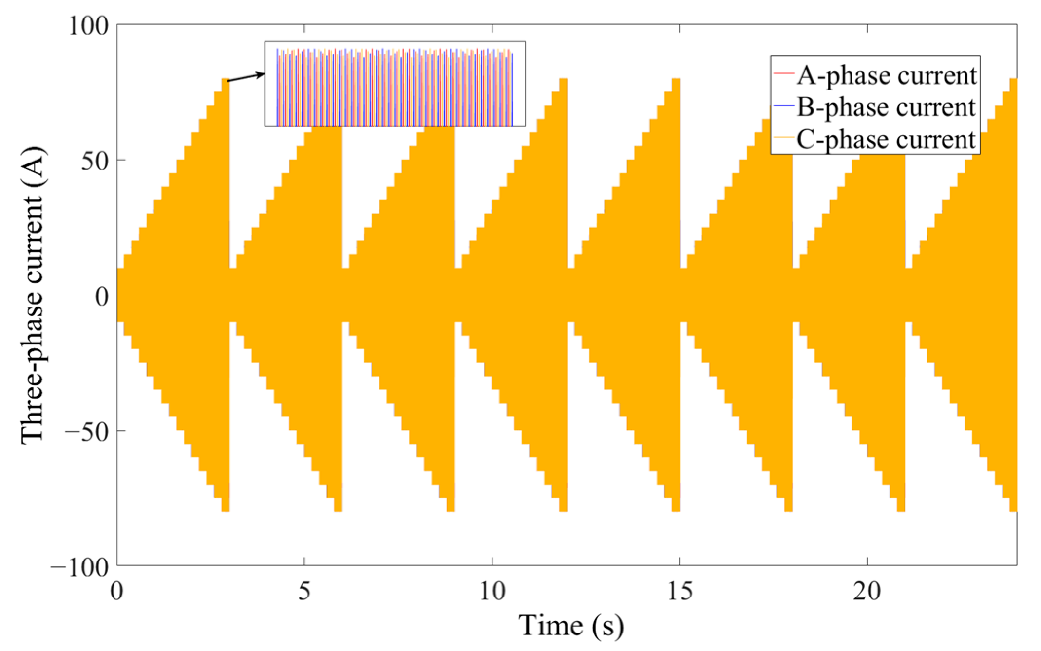
Selection of Training Samples
The construction process of the BP neural network model is very dependent on the input and output data. The selected data should be able to fully reflect the characteristics and changes in the problem domain, and the proportion of various samples in the dataset should be reasonable to avoid too many or too few samples of a certain type. In addition, the selected data should have good accuracy, completeness, and consistency and have a sufficient number of samples. Based on the above requirements, considering the variation range of the input current of the wheel hub motor within the general driving speed range of 10–30 m/s, this paper selects the phase current input with an interval of 5 A within the phase current amplitude range of 10–80 A. Considering the variation interval of the eccentricity of the fixed rotor of the motor during vehicle driving, the input of the eccentricity of the fixed rotor of the motor with an interval of 0.1 mm within the air gap length range of 0.05–0.75 mm is selected as the training sample, as shown in Figure 11 and Figure 12, respectively. This can not only comprehensively reflect the variation intervals of eccentricity and three-phase current amplitudes but also maintain a reasonable number of samples (although increasing the number of samples can improve the approximation effect of the network, an excessive number of samples will significantly increase the training duration and reduce the training efficiency), thereby enabling the trained neural network model to achieve the expected generalization accuracy. The output of the unbalanced electromagnetic force is simulated by the analytical model established above, and then the training sample parameter set containing four input characteristic parameters and one output characteristic parameter is obtained.
(3)
Normalization of Data Processing
The data normalization processing in the BP neural network can not only keep different features in a similar value range, avoid the difficulty of learning rate selection caused by large differences in feature values, so as to make the model converge faster, but also prevent some features from dominating in training due to large value, so that the model can learn the weight of each feature more equitably, improving model accuracy and generalization ability. Since the data selected in this paper are fairly evenly distributed and have clear requirements for data boundaries, linear normalization is adopted:
y = x x min x max x min y max y min + y min
where, x max and x min are the maximum and minimum values of the feature in the sample data, respectively, y is the result after linear normalization, ( y min , y max ) is the specified interval of the linear normalization result, and y is the sample data after linear normalization. After linear normalization of the sample data with the above formula, the final neural network sample input can be obtained.
(4)
Selection of Evaluation Indicators
In this study, the value of Mean Squared Error (MSE) and the value of Coefficient of Determination (R2) are selected as evaluation indices for the prediction performance, and their expressions are as follows [33]:
M S E = 1 n i = 1 n X i m Y i 2
R 2 = 1 i = 1 n X i m Y i 2 i = 1 n X i m X ¯ 2
where, i is the layer i neuron, X i m is the actual output value, Y i is the theoretical output value, and X ¯ is the average value of all samples. Among them, the mean square error calculates the square of the error, amplifies the influence of the larger error, and can more clearly reflect the difference between the predicted value and the real value. When the mean square error value is smaller, the actual output value of the model is closer to the theoretical output value, and the accuracy of the model is higher. The value of the determination coefficient is used to measure the degree to which the independent variable explains the dependent variable in the regression model. It can reflect well the fitting ability of the model. When the value is closer to one, it means that the part of data variation that can be explained by the model accounts for a higher proportion of the total variation, and the fitting ability of the model is stronger at this time; when the value is closer to 0, it means that the predicted value is closer to random, and the fitting ability of the model is weaker.
(5)
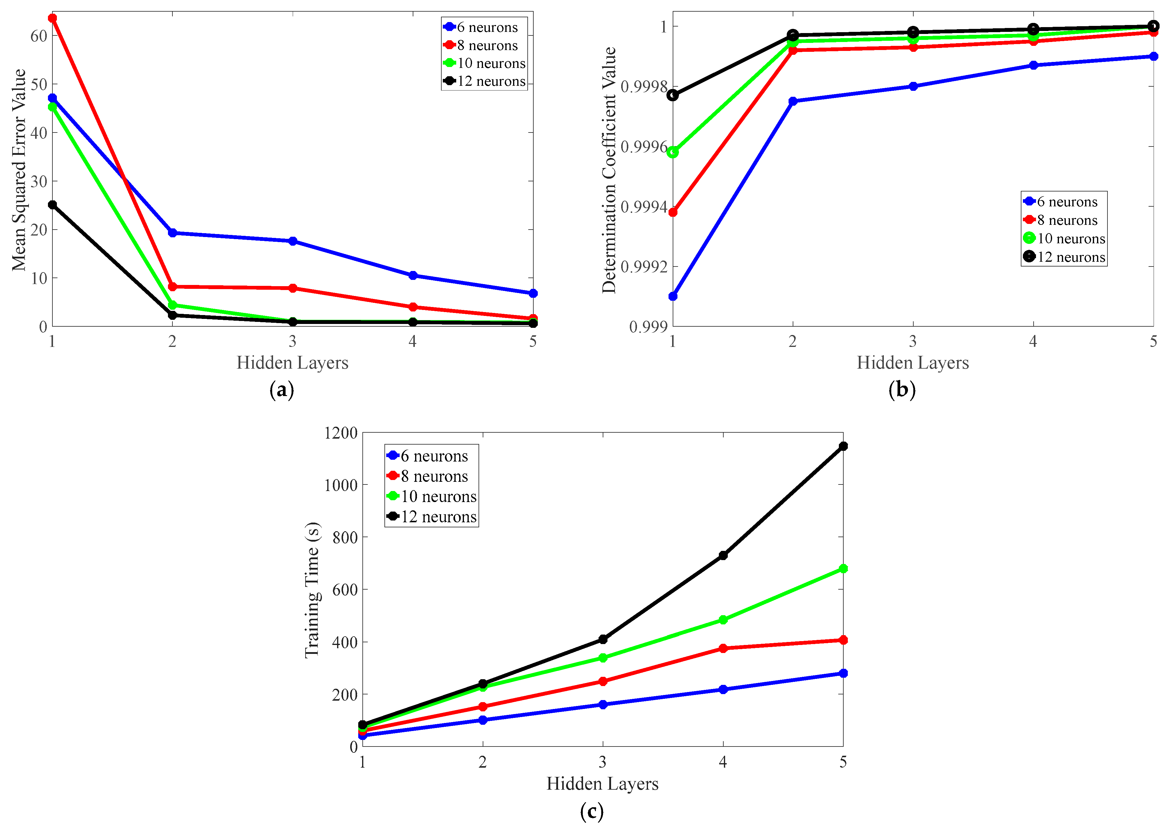
Determine the Number of Hidden Layers and Neurons of the Neural Network
The selection of hidden layers and neurons of the neural network has an important impact on the computational efficiency and fitting accuracy of the model. The number of neurons in the hidden layer is generally selected according to the empirical formula: [34]
a = n + m + b
where, a is the number of neurons in the hidden layer; n and m are the number of neurons in the input and output layers, respectively, and b is a constant between 1 and 10.
According to the above formula, the number of hidden layer neurons is selected as 6, 8, 10, and 12, respectively, and the training effect of the BP neural network model with 1–5 hidden layers is obtained by simulation.
As can be seen from Figure 13a,b, the mean squared error and coefficient of determination are used to evaluate the prediction accuracy and fitting ability of the model, respectively. Increasing the number of hidden layers can significantly reduce the mean squared error value of the model and make the value of the determination coefficient of the model close to one to the greatest extent, but the training time of the model will also increase significantly, as shown in Figure 13c. When the number of hidden layers reaches three or more, the prediction accuracy and fitting ability of the model tend to be stable. At this time, further increasing the number of hidden layers cannot significantly improve the prediction accuracy and fitting ability of the model but will significantly increase the training time and reduce the training efficiency. Therefore, the number of hidden layers of the BP neural network is determined to be three. When the number of neurons in each hidden layer increases, the mean squared error value of the model decreases, and the value of the determination coefficient becomes closer to one. When the number of neurons is increased to a certain number (10 and 12), the model can achieve relatively ideal prediction accuracy and fitting ability. At this time, compared with 12 neurons, the BP neural network model with 10 neurons in the hidden layer has a relatively short training time, so the number of neurons in each hidden layer is determined to be 10. Finally, a BP neural network with a five-layer topology of 4–10–10–10–1 is obtained, as shown in Figure 14.
(6)
Selection of Excitation Function
After several simulations, it was found that the selection of the excitation function had little influence on the calculation results of the model. In order to make the calculation more convenient and enable the BP neural network to fit relatively complex functional relationships, the hyperbolic tangent function and purelin function are selected as the excitation functions of the hidden layer and the output layer, respectively.
(7)
Selection of Training Function
At present, there are mainly three commonly used training functions for BP neural networks: trainlm, trainbr, and trainscg, and their performances are different. In order to select the appropriate training function, simulations under different training functions are carried out. Figure 15 presents the comparison of the training results of each training function under different sample sizes. The mean squared error and coefficient of determination are used to evaluate the prediction accuracy and fitting ability of the model, respectively. It can be seen that for the neural network model trained with the trainlm and trainscg functions, its prediction accuracy improves as the number of samples increases. When the number of samples reaches a certain level, the training effect tends to be stable. The training effect of the neural network trained by the trainbr function is almost unaffected by the number of samples. Moreover, under the same number of samples, the mean squared error value of this neural network model is the smallest, and the determination coefficient value is infinitely close to one. Therefore, the trainbr training function is adopted in this paper.

4.3. Optimization Effect Analysis of Unbalanced Electromagnetic Force Model

According to the above steps, simulation verification under different working conditions is carried out using MATLAB/Simulink/2016b software. Since the accuracy of the analytical model has been verified through finite element simulation in the previous text, the calculation results of the analytical model are adopted here as the true values of the unbalanced electromagnetic force for comparative analysis.
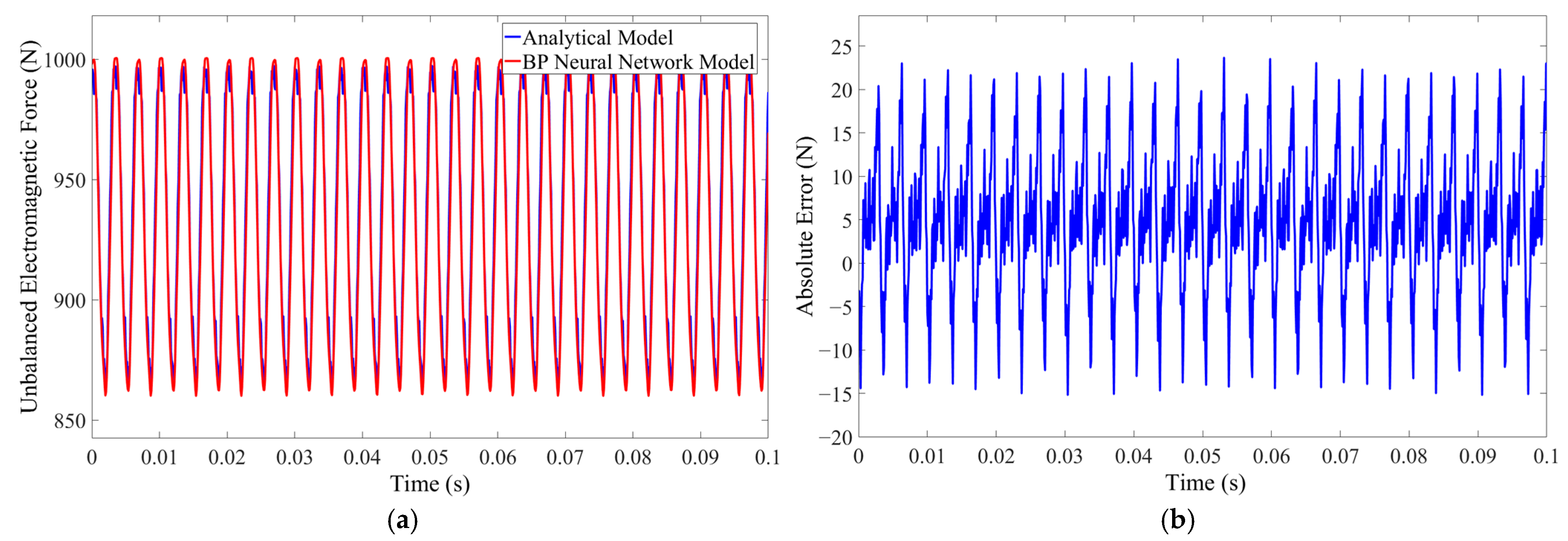
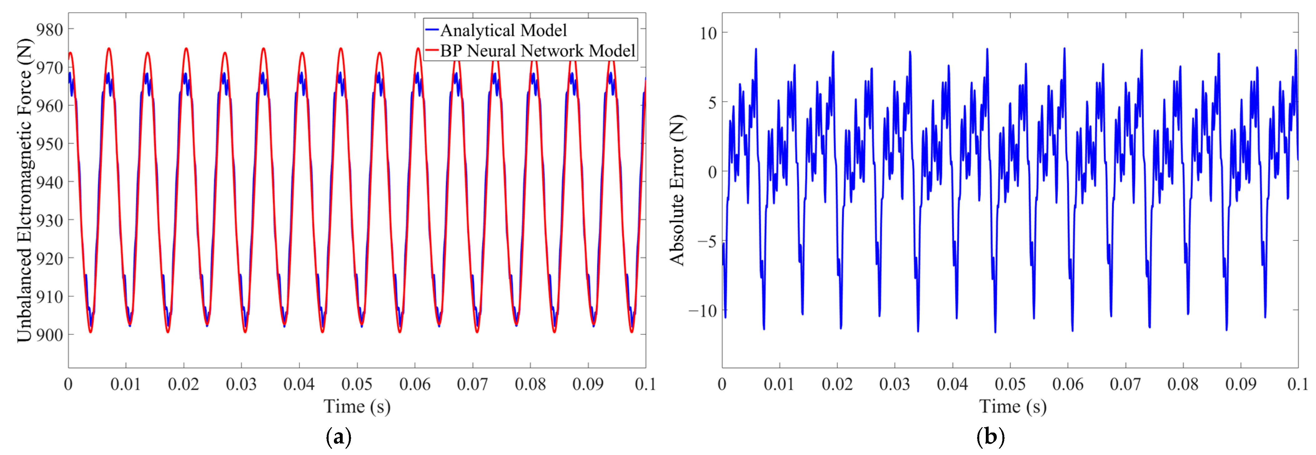
  • Simulation of Ideal Uniform Speed of Motor
Two simulation conditions of motor speed 390 rpm and phase current amplitude 40 A, and motor speed 195 rpm and phase current amplitude 20 A, are set, respectively. The final fitting effects of the BP neural network algorithm are shown in Figure 16 and Figure 17, respectively. It can be seen from the figure that the BP neural network established in this study can fit the unbalanced electromagnetic force through the three-phase current and the eccentricity of the fixed rotor, and the simulation results of the analytical model and the calculation results of the BP neural network have a good consistency in waveform and amplitude.
Among them, under the operating condition of 390 rpm and 40 A phase current amplitude, the root mean square value of the vertical unbalanced electromagnetic force decreases from 937.9 N to 933.3 N, and the error is only 0.49%. Under the operation condition of 195 rpm and 20 A phase current amplitude, the root mean square value of unbalanced electromagnetic force decreases from 938.3 N to 937.5 N, and the error is only 0.085%. The simulation time of 10 s with a fixed step size is reduced from 1 h to about 50 s, and the simulation time, root mean square error, and absolute error are all within the acceptable range. Considering that the calculation time of the BP neural network model is similar under the same simulation time, the comparison of calculation time is not given in the following.
2.
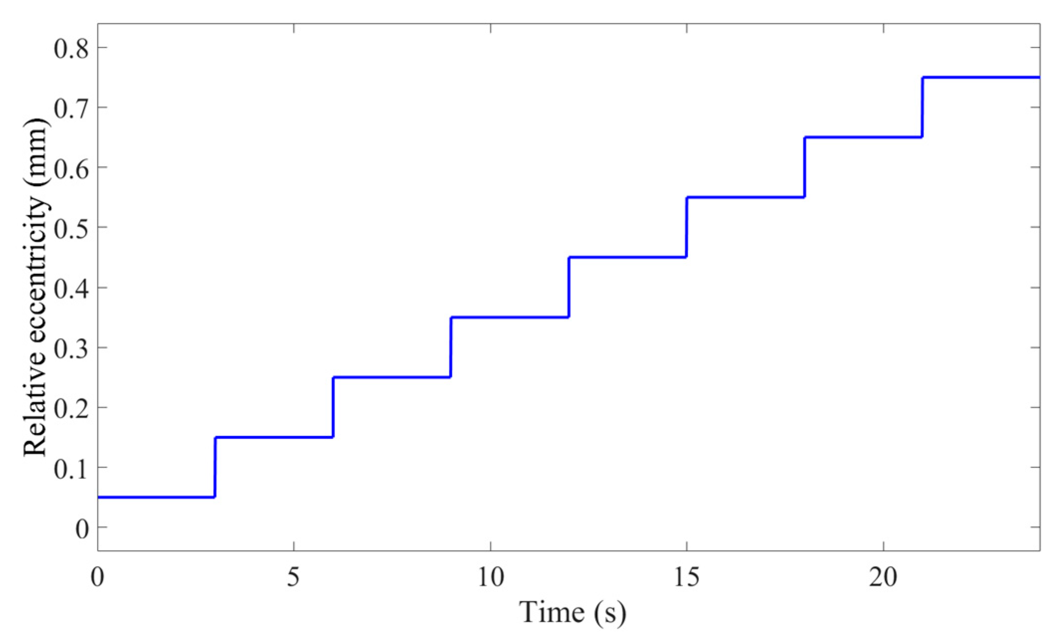
Simulation of Acceleration and Eccentricity Change
In addition to the uniform speed condition, the vehicle has common acceleration and braking conditions in the daily driving process, and the wheel is often accompanied by a change in the eccentricity of the motor’s fixed rotor when the vibration occurs. Here, the case of uniform acceleration is taken as an example; the three-phase current input amplitude is 40 A, the motor speed uniformly rises from 0 to 390 rpm within 0.1 s, and the eccentricity is set as the sine function e = 0.0002 + 0.0002 s i n 400 π t in order to verify the calculation accuracy of the vertical unbalanced electromagnetic force under the condition of uniform acceleration and variable eccentricity close to daily driving. Figure 18 shows the calculation results of the vertical unbalanced electromagnetic force under this input.
As can be seen from Figure 18, the BP neural network model can better fit the unbalanced electromagnetic force under static eccentricity under conditions of uniform acceleration and variable eccentricity, where the root mean square value of the BP neural network model decreases by 0.94% from 574.4 N to 569 N compared with the analytical model. The root mean square error and the absolute error are slightly increased compared with the ideal uniform speed condition of the motor, but they are both within the acceptable range. It can be proved that a BP neural network can still predict the accuracy of vertical unbalanced electromagnetic force well under this condition. The root mean square errors of the analytical model of unbalanced electromagnetic force and the BP neural network model under different working conditions are shown in Table 4.
Based on the above working conditions, BP neural network can achieve accurate calculation of the vertical unbalanced electromagnetic force model under different motor operating conditions and can greatly improve the operating efficiency of the model, which is proved that the unbalanced electromagnetic force model optimized by BP neural network is more suitable for the dynamic simulation of wheel hub direct-drive electric vehicles, thus solving the problem that the traditional unbalanced electromagnetic force model is difficult to couple with the vertical dynamics model of the vehicle in real time. It provides more convenient conditions for the research of the negative effects of vertical vibration on wheel hub direct-drive electric vehicles in the later stage.

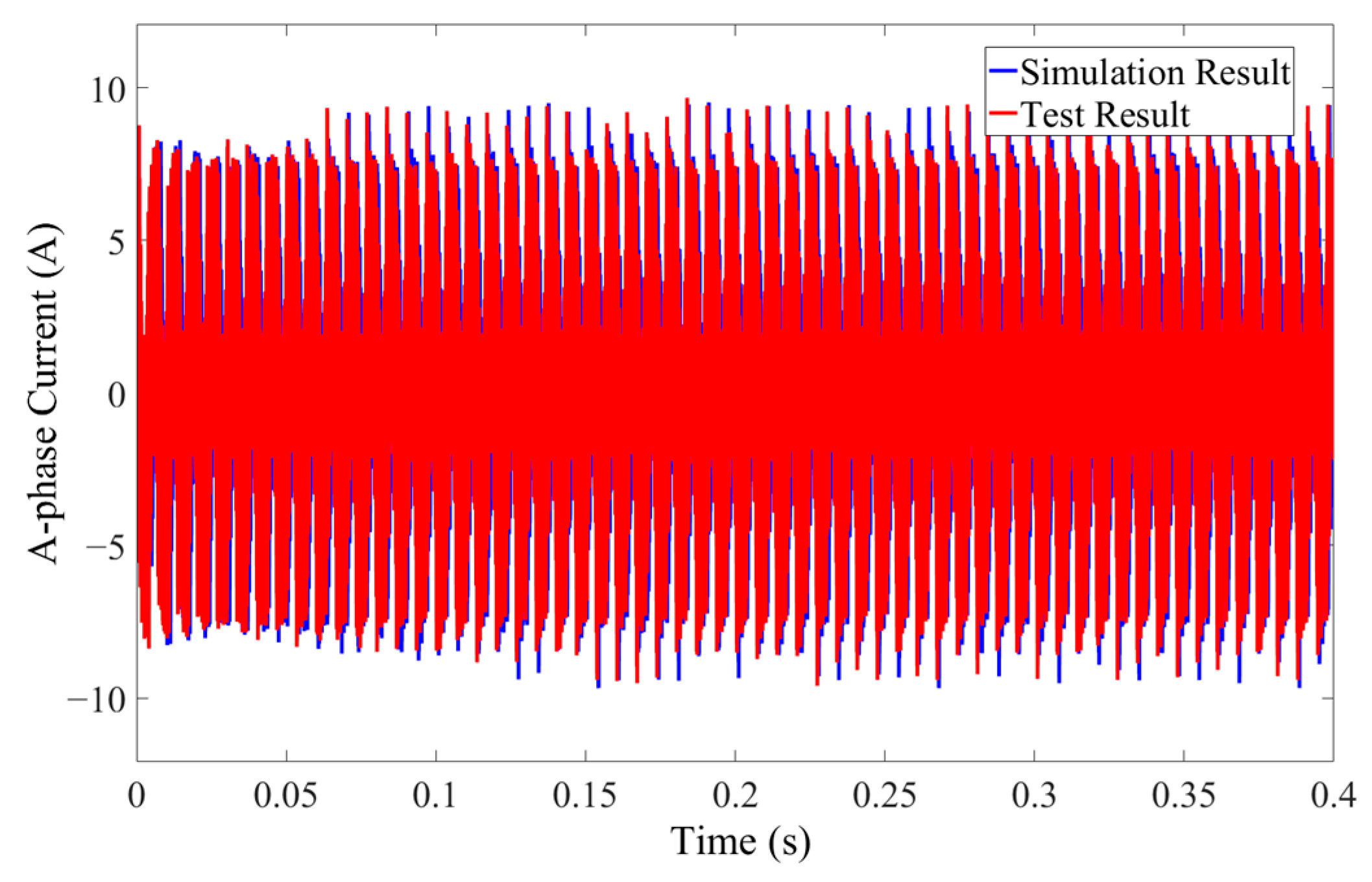
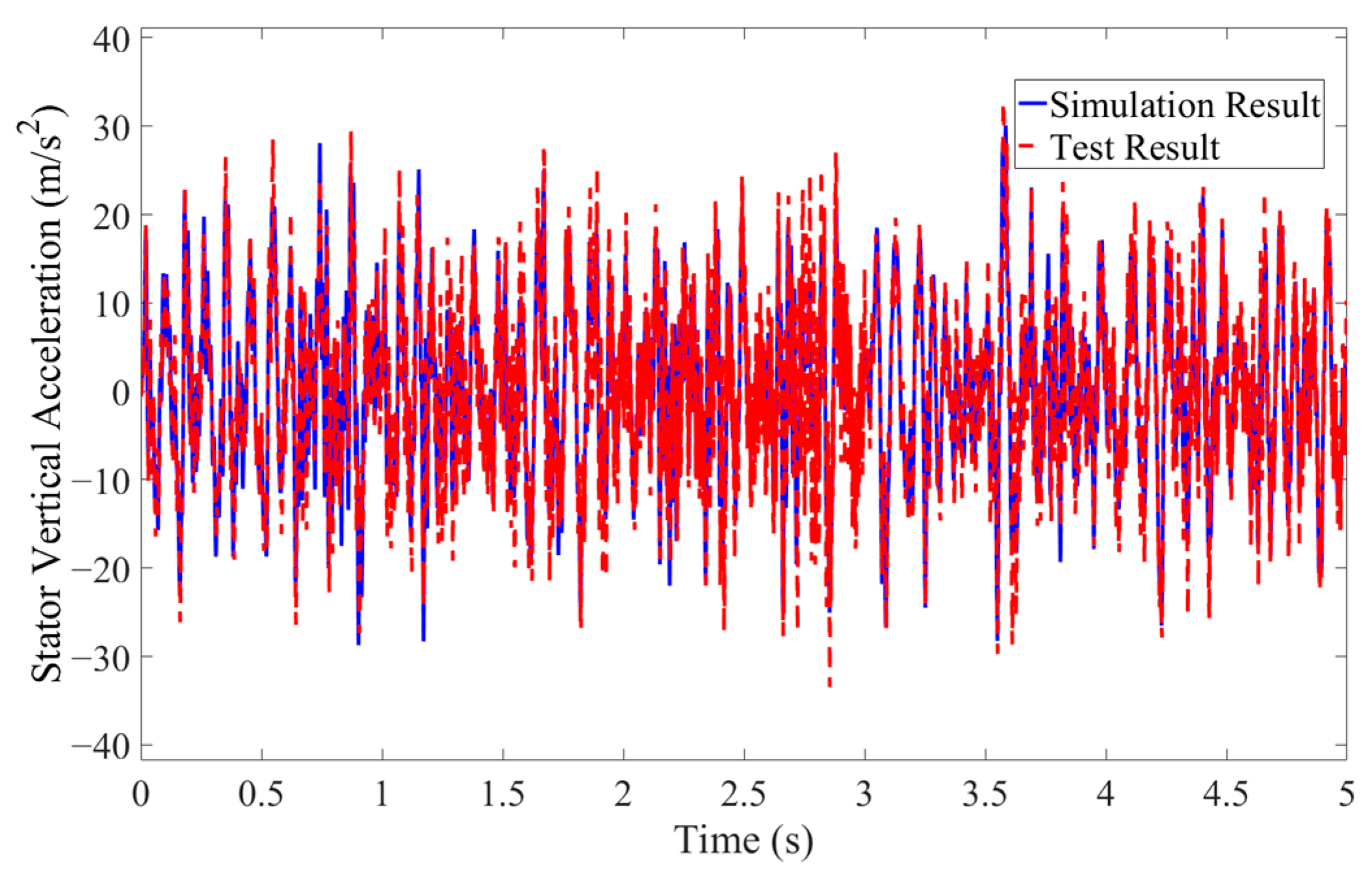
5. Bench Experiment Verification

In order to verify the correctness of the coupling model between the unbalanced electromagnetic force and the vertical dynamics of the vehicle, the single-phase current output from the wheel hub motor model and the stator vertical acceleration output from the coupling model are collected by setting up an experimental bench. At the same time, the coupling model is simulated under the same simulated operating conditions, and the resulting curve is compared with the experimental results to verify the accuracy of the coupling model.
The main structure of the test bench is shown in Figure 19, including the tire, permanent magnet motor, tension pressure sensor, vibration platform, wheel hub motor fixture, current and acceleration sensor, passive suspension, etc. The phase current of the wheel hub motor is collected by a single-channel hydraulic vibration excitation test rig. Due to the obvious vibration of the wheel hub motor near the motor shaft and the low difficulty in arranging the acceleration sensor, a square platform is designed at the connection position between the swing arm and the motor shaft to carry the acceleration sensor to measure the vertical acceleration of the stator. Install the wheel hub motor and the wheel on the drum. The wheel hub motor and wheels are consistent with the specifications of the test prototype vehicle, and the hydraulic excitation platform below is used to simulate road surface excitation. Set the motor speed to 390 rpm, the actuator amplitude of the excitation table to 0.003 m, and the working frequency to 2 Hz. The curve comparison between experimental results and simulation results under the same simulation conditions is shown in Figure 20 and Figure 21.
It can be seen from Figure 20 and Figure 21 that under the same simulation operating conditions, the curves of simulation results and test results have a good consistency in waveform and amplitude. As is shown in Table 5, the root mean square value of the A-phase current decreases from 3.67 A in the simulation to 3.59 A in the test, with a relative error of 2.18%. The root mean square value of the stator vertical acceleration increases from 9.54 m/s2 in simulation to 9.78 m/s2 in test, with a relative error of 2.52%. Considering that some simplification of wheel hub motor structure and vehicle dynamics model was made when the coupling model of unbalanced electromagnetic force and vehicle vertical dynamics was built, and problems such as mechanical wear and measurement accuracy errors existed in the experimental instruments, there are slight errors in the test results and simulation results of single-phase current and stator vertical acceleration, but the overall errors are within an acceptable range. Therefore, it can be proved by experiments that the coupling model built has good accuracy. It also proves that the unbalanced electromagnetic force model optimized by the BP neural network can be coupled with the vertical dynamics model of the vehicle accurately in real time.

6. Conclusions

The permanent magnet synchronous motor system model, air gap magnetic field model, electromagnetic wave model, and unbalanced electromagnetic force model of wheel hub motor under static eccentricity are established by an analytical method, and their accuracy is verified by finite element modeling of the wheel hub motor. The results show that the curve of the unbalanced electromagnetic force model of the wheel hub motor established by the analytical method is basically consistent with the simulation results of finite element modeling, thus verifying the accuracy of the analytical model.
At the same time, the factors affecting the output characteristics of unbalanced electromagnetic force are discussed, and on this basis, the BP neural network model is constructed to optimize the computational efficiency of the unbalanced electromagnetic force analytical model. The results show that, compared with the traditional analytical model, the optimized unbalanced electromagnetic force model takes less time to simulate 10 s from 1 h to about 50 s and has good accuracy under various working conditions. It is proven that the BP neural network can greatly improve the calculation efficiency of the unbalanced electromagnetic force without affecting the accuracy of the model, effectively solving the problem that the traditional unbalanced electromagnetic force model is difficult to couple with the vehicle dynamics model in real time.
By setting up an experimental bench to collect the single phase current and stator vertical acceleration of the wheel hub motor and comparing with the simulation results, it is further proved that the unbalanced electromagnetic force model optimized by BP neural network can accurately couple with the vertical dynamics model of the vehicle in real time, which provides an unbalanced electromagnetic force model that is more suitable for the dynamic simulation of wheel hub direct-drive electric vehicles and lays a better foundation for the subsequent research on the vertical vibration effect of wheel hub direct-drive electric vehicles.

Author Contributions

Conceptualization, X.M. and R.D.; methodology, W.L.; software, Y.Z.; validation, Y.Z.; formal analysis, Y.Z.; investigation, W.L.; resources, X.M.; data curation, Y.Z.; writing—original draft preparation, Y.Z.; writing—review and editing, Y.Z.; visualization, Y.Z.; supervision, X.M., R.D., W.L. and R.W.; project administration, R.W.; funding acquisition, X.M. All authors have read and agreed to the published version of the manuscript.

Funding

This research was funded by [National Natural Science Foundation Project of China] grant number [52472410] and [“Unveiling the List and Taking Command” Tackling Project of Nantong] grant number [JB2022003].

Data Availability Statement

The original contributions presented in this study are included in the article. Further inquiries can be directed to the corresponding author.

Conflicts of Interest

The authors declare no conflicts of interest.

References

  1. Li, Y.; Xu, X.; Sun, X.; Jiang, H.; Qu, Y. Research and Development of wheel Motor Drive Technology. Electr. Mach. Control Appl. 2017, 44, 1–7. [Google Scholar]
  2. Wang, Z.; Ding, X.; Zhang, L. Review on Key Technologies of Anti-skid Control for Vehicle Driven by four-wheel hub Motor. Chin. J. Mech. Eng. 2019, 55, 99–120. [Google Scholar]
  3. Zhao, Z.; Taghavifar, H.; Du, H.; Qin, Y.; Dong, M.; Gu, L. In-Wheel Motor Vibration Control for Distributed-Driven Electric Vehicles: A Review. IEEE Trans. Transp. Electrif. 2021, 7, 2864–2880. [Google Scholar] [CrossRef]
  4. Yang, X.; Song, H.; Shen, Y.; Liu, Y. Study on adverse effect suppression of hub motor driven vehicles with inertial suspensions. Proc. Inst. Mech. Eng. Part D J. Automob. Eng. 2021, 236, 767–779. [Google Scholar] [CrossRef]
  5. Wang, R.; Jiang, Y.; Ding, R.; Liu, W.; Meng, X.; Sun, Z. Design and experimental verification of self-powered electromagnetic vibration suppression and absorption system for in-wheel motor electric vehicles. J. Vib. Control. 2021, 28, 2544–2555. [Google Scholar] [CrossRef]
  6. Kartal, E.T.; Arabul, F.K. Effects of air gap eccentricity on different rotor structures for PMSM in electric vehicles. Sci. Rep. 2024, 14, 17335. [Google Scholar] [CrossRef]
  7. Deng, Z.; Li, X.; Li, X.; Zhao, S.; Wei, H. Mechanism analysis and optimum control of negative airgap eccentricity effect for in-wheel switched reluctance motor driving system. Nonlinear Dyn. 2023, 111, 9075–9093. [Google Scholar] [CrossRef]
  8. Li, X.; Deng, Z.; Chen, T.; Zhang, Y.; Wei, H. Negative dynamics effect of in-wheel switched reluctance motor with inclined airgap eccentricity on handing stability for electric vehicle. Proc. Inst. Mech. Eng. Part D J. Automob. Eng. 2023, 238, 3707–3720. [Google Scholar] [CrossRef]
  9. Zhang, H.; Wan, S.; Zhang, M.; G, J. Analysis on coupled vibration characteristics of electric vehicle’s in-wheel motor with random excitation. J. Mech. Des. 2024, 41, 146–152. [Google Scholar]
  10. Zhu, Z.Q.; Howe, D.; Bolte, E.; Ackermann, B. Instantaneous magnetic field distribution in brushless permanent magnet DC motors. I. Open-circuit field. IEEE Trans. Magn. 1993, 29, 124–135. [Google Scholar] [CrossRef]
  11. Zhu, Z.; Howe, D. Instantaneous magnetic field distribution in brushless permanent magnet DC motors. II. Armature-reaction field. IEEE Trans. Magn. 1993, 29, 136–142. [Google Scholar] [CrossRef]
  12. Zhu, Z.; Howe, D. Instantaneous magnetic field distribution in brushless permanent magnet DC motors. III. Effect of stator slotting. IEEE Trans. Magn. 1993, 29, 143–151. [Google Scholar] [CrossRef]
  13. Zhu, Z.; Howe, D. Instantaneous magnetic field distribution in permanent magnet brushless DC motors. IV. Magnetic field on load. IEEE Trans. Magn. 1993, 29, 152–158. [Google Scholar] [CrossRef]
  14. Sun, J.; Hu, X. Research on Optimization and Control of Vertical Vibration System of Distributed Electric Drive Vehicle. J. Chongqing Univ. Technol. (Nat. Sci.) 2022, 36, 45–52. [Google Scholar]
  15. Ma, C.; Chen, C.; Li, Q.; Gao, H.; Kang, Q.; Fang, J.; Cui, H.; Teng, K.; Lv, X. Analytical Calculation of No-Load Magnetic Field of External Rotor Permanent Magnet Brushless Direct Current Motor Used as In-Wheel Motor of Electric Vehicle. IEEE Trans. Magn. 2018, 54, 8103106. [Google Scholar] [CrossRef]
  16. Ma, C.; Cui, H.; Zheng, P.; Zhang, Y.; Gao, H. Influence of static eccentricity on unbalanced magnetic force of external rotor permanent magnet brushless direct current motor used as In-wheel motor. IET Electr. Power Appl. 2019, 13, 538–550. [Google Scholar] [CrossRef]
  17. Zhang, H.S.; Deng, Z.X.; Yang, M.L.; Zhang, Y.; Tuo, J.Y.; Xu, J. Analytical Prediction of Halbach Array Permanent Magnet Machines Considering Finite Tooth Permeability. IEEE Trans. Magn. 2020, 56, 8101010. [Google Scholar] [CrossRef]
  18. Zhang, H.S.; Yang, M.L.; Zhang, Y.; Tuo, J.Y.; Luo, S.; Xu, J. Analytical Calculation of Surface-Inset PM In-Wheel Motors and Reduction of Torque Ripple. IEEE Trans. Magn. 2020, 57, 8100211. [Google Scholar] [CrossRef]
  19. Du, G.; Deng, Z.; Zhang, H.; Yang, M.; Tang, X. Analytical modeling and pole-slot combination of magnetic field in surface-mounted permanent-magnet synchronous motor. J. Chongqing Univ. 2021, 44, 1–13. [Google Scholar]
  20. Chen, X.; Deng, Z.; Hu, J.; Deng, T. An analytical model of unbalanced magnetic pull for PMSM used in electric vehicle: Numerical and experimental validation. Int. J. Appl. Electromagn. Mech. 2017, 54, 583–596. [Google Scholar] [CrossRef]
  21. Yang, Z.; Sun, C.; Sun, X.; Sun, Y. An Improved Dynamic Model for Bearingless Induction Motor Considering Rotor Eccentricity and Load Change. IEEE Trans. Ind. Electron. 2021, 69, 3439–3448. [Google Scholar] [CrossRef]
  22. Deng, Z.; Li, X.; Liu, T.; Zhao, S. Modeling and suppression of unbalanced radial force for in-wheel motor driving system. J. Vib. Control. 2021, 28, 3108–3119. [Google Scholar] [CrossRef]
  23. Li, Z.; Wang, X.; Cheng, Q.; Yu, Y. Research on GA-LQR Control for Air Suspension Damping of Electric Vehicle with Wheel Motor. J. Chongqing Univ. Technol. 2024, 38, 13–23. [Google Scholar]
  24. Li, T.; Deng, Z.; Zhang, H.; Lu, P.; Zeng, P. Vertical Dynamics Characteristics of Electromechanical Coupling of Electric Vehicle Driven by hub Motor. J. Chongqing Univ. 2024, 47, 1–17. [Google Scholar]
  25. Wu, S.; Li, Y. Analysis of Effect of unbalanced electromagnetic Force of Wheel Motor on Vertical Vibration of Vehicle. J. Harbin Univ. Sci. Technol. 2022, 27, 21–28. [Google Scholar]
  26. Li, J.; Jia, C.; Cheng, L.; Zhao, Q. Influence of eccentricity of wheel motor under Random Road Surface on Ride Comfort of Electric Vehicle. J. Northeast. Univ. (Nat. Sci.) 2022, 43, 1113–1119. [Google Scholar]
  27. Li, J.; Jia, C.; Cheng, L.; Zhao, Q. Influence of eccentricity of wheel motor under Pulse Road Surface on Ride Comfort of Electric Vehicle. J. Northeast. Univ. (Nat. Sci.) 2022, 12, 321–328. [Google Scholar]
  28. Yuan, L.; Hu, B.; Wei, K.; Chen, S. Modern Permanent Magnet Synchronous Motor Control Principle and MATLAB Simulation; Beijing University of Aeronautics and Astronautics Press: Beijing, China, 2016; pp. 151–165. [Google Scholar]
  29. Shu, Z.; Liu, L. No-beat Predictive Current Control of Permanent magnet synchronous Motor Based on Parameter Adaptive. Electr. Power Eng. Technol. 2019, 42, 175–184. [Google Scholar]
  30. Kurihara, N.; Bayless, J.; Chiba, A. Noise and vibration reduction of switched reluctance motor with novel simplified current waveform to reduce force sum variation. In Proceedings of the 2015 IEEE International Electric Machines & Drives Conference (IEMDC), Coeur d’Alene, ID, USA, 10–13 May 2015; pp. 1794–1800. [Google Scholar]
  31. Zhang, H.; Wan, S.; Zhang, M. Coupling Vibration Suppression of In-Wheel Motor Electric Vehicle Based on Active Disturbance Rejection Control. Automot. Technol. 2023, 8–14. [Google Scholar]
  32. Xing, Y.; Li, F. Research on the influence of hidden layers on the prediction accuracy of GA-BP neural network. J. Phys. Conf. Ser. 2020, 1486, 022010. [Google Scholar] [CrossRef]
  33. He, X.; Zhao, Y.; Cai, C. Random Vibration Analysis of Vehicle-Rail-Bridge System based on SSA-BP Neural Network. J. Railw. Sci. Eng. 2024, 21, 3225–3236. [Google Scholar]
  34. Zhang, X.; Zhang, R.; Chen, X.; Yang, H.; Yu, D.; Song, Y. Strength evolution prediction of structural concrete in Long Service period based on GA-BP neural network. J. Cent. South Univ. (Nat. Sci.) 2024, 55, 836–850. [Google Scholar]
Figure 1. Star diagram of magnetic potential vector of three-phase armature winding.
Wevj 16 00252 g001
Figure 2. Static eccentricity diagram of wheel motor.
Wevj 16 00252 g002
Figure 3. Variation in unbalanced electromagnetic force with eccentricity. (a) Phase 20 A current amplitude. (b) Phase 40 A current amplitude.
Wevj 16 00252 g003
Figure 4. Variation in unbalanced electromagnetic force with phase current amplitude. (a) 0.2 mm eccentricity. (b) 0.6 mm eccentricity.
Wevj 16 00252 g004
Figure 5. Permanent magnet synchronous motor grid model finite element simulation diagram.
Wevj 16 00252 g005
Figure 6. Verification effect of synthetic air gap magnetic field under static eccentricity. (a) Verification effect of radial air gap magnetic field. (b) Verification effect of tangential air gap magnetic field.
Wevj 16 00252 g006
Figure 7. Verification effect of electromagnetic wave under static eccentricity. (a) Radial electromagnetic wave verification effect. (b) Tangential electromagnetic wave verification effect.
Wevj 16 00252 g007
Figure 8. The logical block diagram of the coupling model of unbalanced electromagnetic force and vehicle dynamics.
Wevj 16 00252 g008
Figure 9. The mini-car used in the study.
Wevj 16 00252 g009
Figure 10. Vertical vibration model of half-car of wheel hub direct-drive electric vehicle.
Wevj 16 00252 g010
Figure 11. Training sample of fixed rotor eccentricity.
Wevj 16 00252 g011
Figure 12. Three-phase current training sample.
Wevj 16 00252 g012
Figure 13. The relationship between the training effect of BP neural network and the number of hidden layers and the number of neurons. (a) The relationship of mean squared error value with the number of hidden layers and the number of neurons. (b) The relationship of determination coefficient value of hidden layers and the number of neurons. (c) The relationship of training time with the number of hidden layers and the number of neurons.
Wevj 16 00252 g013
Figure 14. A 4–10–10–10–1 BP neural network structure.
Wevj 16 00252 g014
Figure 15. Comparison of training results of each training function under different sample sizes.
Wevj 16 00252 g015
Figure 16. Motor unbalanced electromagnetic force output comparison at 390 rpm, 40 A. (a) The fitting effect of BP neural network. (b) The absolute error of BP neural network model and analytical model.
Wevj 16 00252 g016
Figure 17. Motor unbalanced electromagnetic force output comparison at 195 rpm, 20 A. (a) The fitting effect of BP neural network. (b) The absolute error of BP neural network model and analytical model.
Wevj 16 00252 g017
Figure 18. Motor unbalanced electromagnetic force output comparison at uniform acceleration and variable eccentricity. (a) The fitting effect of BP neural network. (b) The absolute error of BP neural network model and analytical model.
Wevj 16 00252 g018
Figure 19. Experimental bench.
Wevj 16 00252 g019
Figure 20. Comparison between simulation and test of single-phase current.
Wevj 16 00252 g020
Figure 21. Comparison between simulation and test of stator vertical acceleration.
Wevj 16 00252 g021
Table 1. Nominal parameters of the permanent magnet synchronous motor.
Nominal
Parameters
Rated PowerRated VoltageEquivalent
Resistance of the Stator
Three-Phase Winding
Self-Inductance
The Moment of Inertia of the Rotor
Numerical value4 kw72 V0.3 Ω 2.9 × 10 5 H 0.02   kg · m 2
Table 2. Wheel hub motor simulation parameter.
Parameter NameParameter
Symbol
Parameter ValueUnit
Unit motor winding pitch α y 0.123rad
Number of turns per slot of windingN24-
Number of slots Q s 51-
Number of poles2p46-
Relative permeability of permanent magnet μ r 1.1-
Number of parallel branchesa1-
Polar arc coefficient α p 1-
Outer diameter of stator coreR100mm
Thickness of permanent magneth2.5mm
Radius of permanent magnetR100.8mm
Axial length of the motorL60mm
Width of notch b 0 2.14mm
Residual magnetic inductionB1.04T
Notch angle α 0 0.0214rad
Table 3. A 1/2 vertical vehicle dynamics model parameter table.
Physical QuantitySymbolParameter ValueUnit
Quality
parameter
Mass of rotor and tire m u r 1 , m u r 2 17kg
Mass of stator and shaft m u s 1 , m u s 2 22.5kg
Mass of vehicle body m s 355kg
Moment of inertia at the center of mass of the car bodyJ1192 kg · m 2
Stiffness
parameter
Tire stiffness k t 2 , k t 2 200,000N/m
Motor bearing stiffness k b 1 , k b 2 4,000,000N/m
Suspension stiffness k s 1 , k s 2 15,000/17,000N/m
Damping
parameter
Suspension damping c s 1 , c s 2 1450N·s/m
Geometric
parameter
Distance from front/rear wheels to body center of massa/b0.795/0.975m
Table 4. Root mean square error of analytical model and BP neural network model under different working conditions.
Working ConditionAnalytical ModelBP Neural Network ModelRelative Error of Root Mean Square Value
390 rpm speed, 40 A phase current amplitude937.9 N933.3 N0.49%
195 rpm speed, 20 A phase current amplitude938.3 N937.5 N0.085%
uniform acceleration and variable eccentricity574.4 N569 N0.94%
Table 5. Root mean square error of simulation results and test results.
Comparison ObjectSimulation ResultTest ResultRelative Error of Root Mean Square Value
A-phase current3.67 A3.59 A2.18%
Stator vertical acceleration9.54 m/s29.78 m/s22.52%
Disclaimer/Publisher’s Note: The statements, opinions and data contained in all publications are solely those of the individual author(s) and contributor(s) and not of MDPI and/or the editor(s). MDPI and/or the editor(s) disclaim responsibility for any injury to people or property resulting from any ideas, methods, instructions or products referred to in the content.

