Article

Optimal Power Control of Inverter-Based Distributed Generations in Grid-Connected Microgrid

by
Mohamed A. Hassan
1,*,
Muhammed Y. Worku
1 and
Mohamed A. Abido
2,3
1
Center for Engineering Research, Research Institute, King Fahd University of Petroleum & Minerals, 31261 Dhahran, Saudi Arabia
2
Electrical Engineering Department, King Fahd University of Petroleum & Minerals, Dhahran 31261, Saudi Arabia
3
Senior Researcher at K. A. CARE Energy Research & Innovation Center, Dhahran 31261, Saudi Arabia
*
Author to whom correspondence should be addressed.
Sustainability 2019, 11(20), 5828; https://doi.org/10.3390/su11205828
Submission received: 9 September 2019 / Revised: 15 October 2019 / Accepted: 16 October 2019 / Published: 21 October 2019
(This article belongs to the Special Issue Integration of AC/DC Microgrids into Power Grids)

Abstract

:
Distributed generation (DG) units are utilized to feed their closed loads in the autonomous microgrid. While in the grid-connected microgrid, they are integrated to support the utility by their required real and reactive powers. To achieve this goal, these integrated DGs must be controlled well. In this paper, an optimal PQ control scheme is proposed to control and share a predefined injected real and reactive powers of the inverter based DGs. The control problem is optimally designed and investigated to search for the optimal controller parameters by minimizing the error between the reference and calculated powers using particle swarm optimization (PSO). Microgrid containing inverter-based DG, PLL, coupling inductance, LC filter, power and current controllers is implemented on MATLAB. Two microgrid cases with different structure are studied and discussed. In both cases, the microgrid performance is investigated under different disturbances such as three-phase fault and step changes. The simulation results show that the proposed optimal control improves the microgrid dynamic stability. Additionally, the considered microgrids are implemented on real time digital simulator (RTDS). The experimental results verify the effectiveness and tracking capability of the proposed controllers and show close agreement with the simulation results. Finally, the comparison with the literature confirms the effectiveness of the proposed control scheme.

1. Introduction

With the fast-growing greenhouse gas emissions and other environmental issues, distributed generations (DGs) are rapidly connected to the electricity network [1,2]. Connecting different distributed energy resources (DER) with a group of loads is defined as a microgrid [3]. It acts as a single controllable entity with respect to the grid where it can be connected or disconnected from the grid to operate in both grid-connected and island modes respectively [3]. Different renewable sources and microgrid objectives such as stability, reliability resource penetration, AC and DC analysis, sustainability analysis, controlling voltage source converter (VSC) and DG integration are recently discussed extensively [4,5,6,7,8]. Integrating DGs with the grid can solve several typical problems of conventional AC network such as energy security and cost saving [2]. Microgrid capability to inject power to the grid while maintaining the system stability after getting disturbed is considered as one of the microgrid challenges [9,10]. Different control techniques such as active–reactive power control (PQ control), active power–voltage control (PV control) and voltage–frequency control (VF control) are utilized to control the DG units and achieve the required goals [11,12]. PQ scheme is used to control the exchanged real and reactive powers between the DG and grid [11]. Vf control is employed to keep the inverter voltage at constant value and return the frequency to its nominal value after getting real power disturbance [12]. For integrating inverter-based DG with the power system, several PQ control schemes such as hysteresis, dead-beat (DB) controllers, proportional–integral (PI) controllers and proportional–resonant (PR) have been proposed [13,14,15,16,17,18,19]. Hysteresis control is simple and has fast responses, but the output current contains high ripples leading to poor current quality and finding some difficulties to design the output filter [13]. DB predictive control is widely used because it offers high performance for current-controlled DGs. Nevertheless, it is quite complicated and sensitive to system parameters [14]. If the target is to compensate multiple harmonics behind eliminate the steady-state error and regulate the sinusoidal signals, PR control scheme in the stationary (α, β) reference frame is popular [15]. However, to maintain good performance, the resonant frequency and the varying grid frequency should be identical [16]. PI controller has many advantages such as instantaneous control, better wave shaping and fixed inverter switching frequency resulting in known harmonics [17,18,19]. PQ controller usually adopts double loop controls [20]. Based on power target, the outer power loop produces the reference current while the current inner loop plays the role of fine-tuning [20]. The current control is implemented in the rotating (synchronous) dq reference frame because the synchronous frame controller can eliminate steady state error and has fast transient response.
In the literature, several PQ control techniques have been presented to control the injected powers of the DGs in the grid-connected microgrid [21,22,23,24,25,26]. In our previous work [21], a power controller was implemented to calculate the dq reference currents using the dq output voltages and reference real and reactive powers. Utilizing Newton–Raphson-based parameter estimation and feed forward control approaches, a robust servomechanism voltage controller and a discrete-time sliding mode current controller were used to control the DG power flow in the grid-connected mode [22]. For a single-phase grid-connected fuel cell system, a second order generalized integrator to control the active and reactive powers was presented [23]. Based on six control degrees, an individual-phase decoupled PQ controller was anticipated for a three-phase VSC [24]. In grid-connected microgrid, utilizing maximum power point tracking (MPPT), a PQ control method was proposed to control the power of the solar photovoltaic and battery storage [25]. PQ control was used in the load-following mode and PV control was utilized in maximum power point tracking mode to control a solar photovoltaic in distribution systems [26]. Unfortunately, all the previous presented work suffers from the bad performance especially under dynamic loads and generation variations since they are relying on deeply empirical engineering rules for designing the multivariable parameters of the PQ controllers [26]. Designing an optimal PQ controller is essentially to overcome the aforementioned problems and to solve the constrained optimization problem [26]. Recently, optimal control using swarm algorithms and popular evolutionary has been effectively utilized in power systems and power converters [27,28,29,30,31,32]. Moreover, designing an optimal PQ controller has been reported in a few works [26], [30]. In [26], an optimal active and reactive power control was developed for a three-phase grid-connected inverter in a microgrid by using an adaptive population-based extremal optimization algorithm (APEO). In the grid-connected microgrid, a particle swarm optimization (PSO)-based PQ control technique under variable loads conditions was proposed [30]. This important work has confirmed the importance of PSO in the automatic tuning of PQ control parameters for optimized operation during abrupt load changes. However, this work did not optimize the controller parameters of the two current controllers in the designed control system. Therefore, the problem may not be considered as an incomplete optimization process for designing PQ controllers [26]. Moreover, they did not consider the optimization of the filter components which they have a great effect on the microgrid stability [3]. Additionally, the microgrid will be under more stress and the controller design needs to be more accurate when we have a generation disturbance not a load disturbance as presented in [26].
In this paper, an efficient PI power controller is proposed to regulate the predefined injected real and reactive powers to the grid. The control problem is optimally designed based on minimizing the error between the calculated and the injected powers to get the optimal controller parameters. Particle swarm optimization (PSO) is employed to design the controller parameters and LC filter components. Different microgrid structures are implemented and examined in MATLAB. Firstly, the optimal proposed controller is designed to control the injected real and reactive powers of one inverter-based DG. Secondly, the optimal proposed controller is designed for two different rated inverter-based DG units to share their injected powers to the grid. Sever disturbances such as step up/down changes of real and reactive injected powers, three-phase fault and losing DG unit are applied to investigate the proposed controller effectiveness and to ensure the system stability after getting disturbed. Additionally, to validate the usefulness of the proposed controller, the considered microgrid is implemented on real time digital simulator (RTDS). To confirm the effectiveness of the proposed optimal control scheme, it is compared with the exiting work in [21] through extensive simulation and experiments under various disturbances. The results confirm the superiority of the proposed control strategy in providing a fast, accurate and decoupled power control with a lower AC current distortion.
The major contributions of this work are described as follows:
(1)
A new optimal PQ control scheme is proposed for inverter-based grid-connected microgrid to improve the microgrid dynamic stability.
(2)
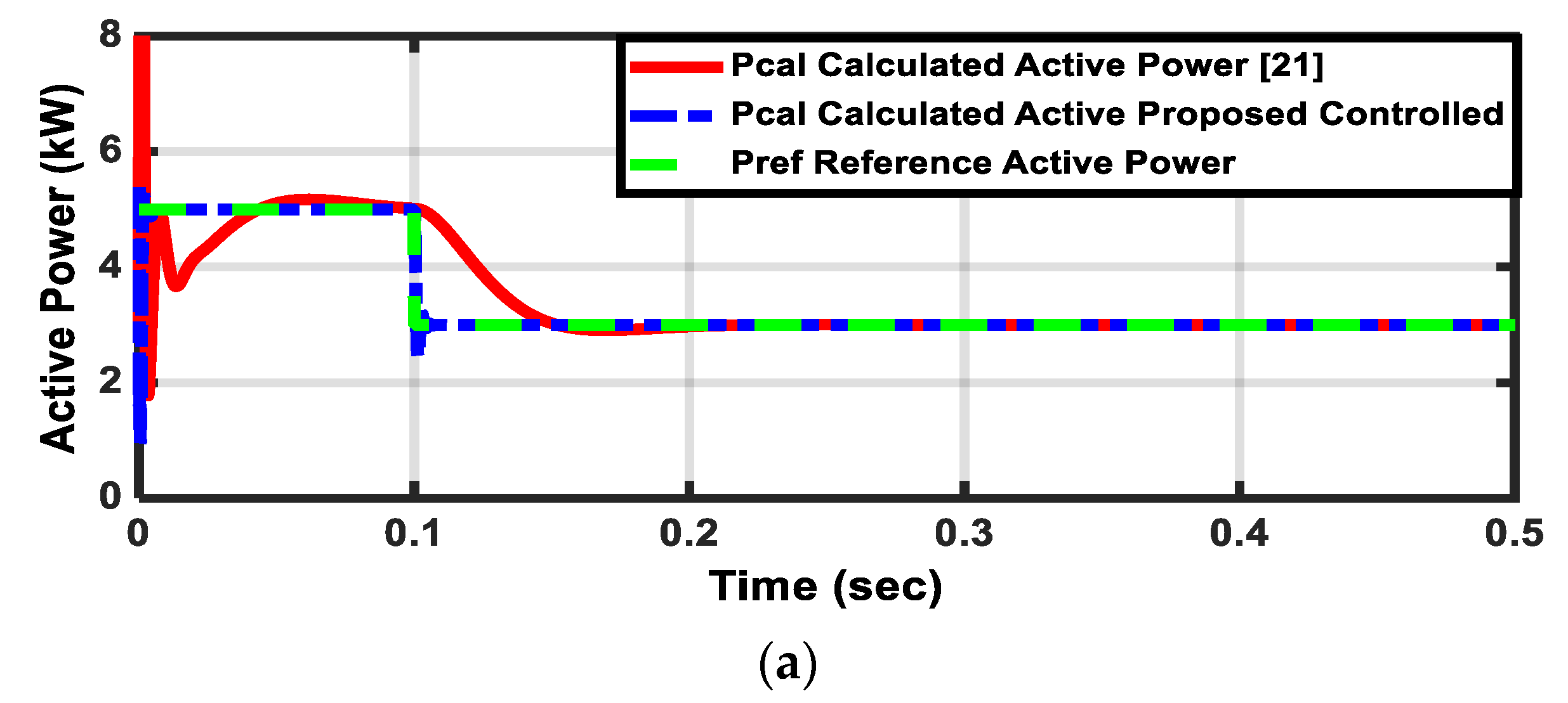
The proposed scheme is compared with the exciting control scheme to validate the proposed controller robustness. The superiority of the proposed control is confirmed using both MATLAB simulation and RTDS experimental results for an inverter-based grid-connected microgrid.
(3)
The proposed controller has been verified for a two inverter-based grid-connected microgrid.
(4)
To the best of the authors’ knowledge, an optimal PQ control technique is firstly implemented in real time digital simulator (RTDS) to control the injected real and reactive powers of the inverter-based DGs in the grid-connected microgrid.
(5)
The superiority of the proposed method is demonstrated by experimental results using RTDS.

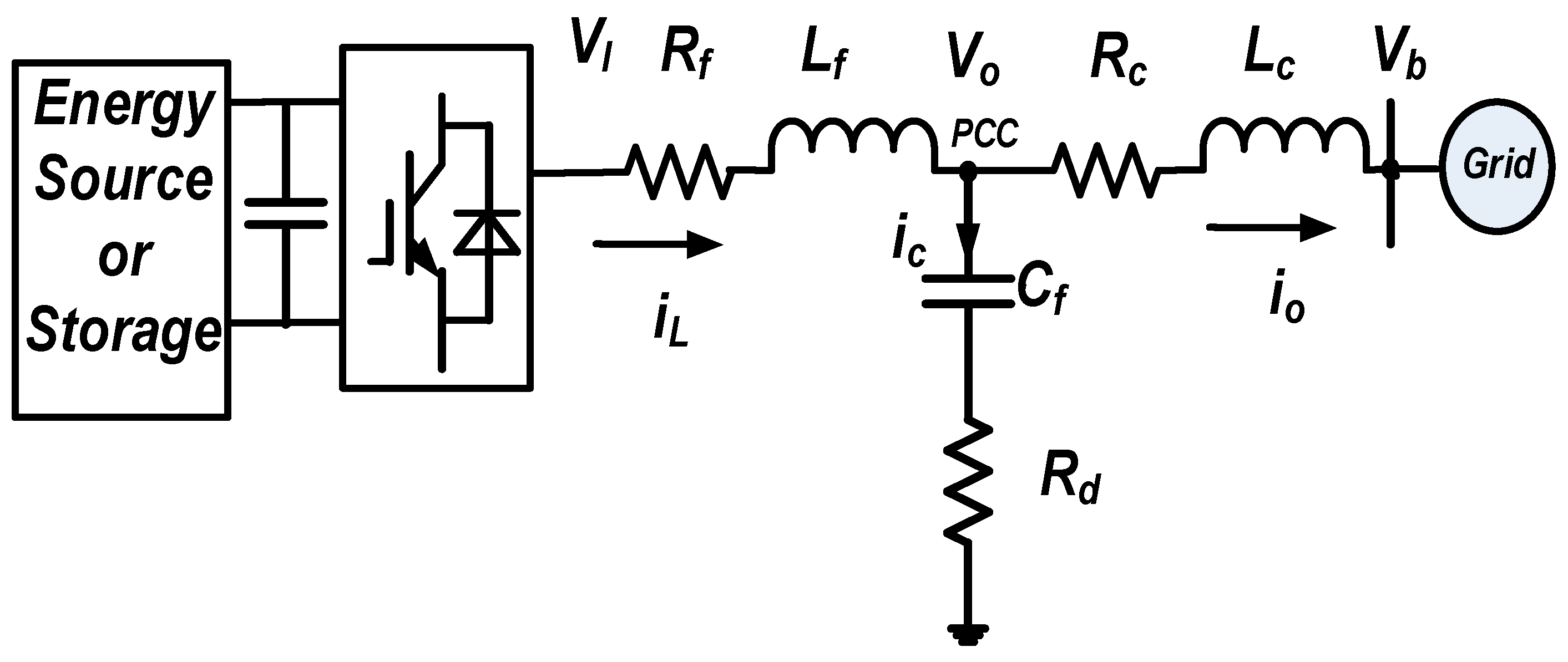
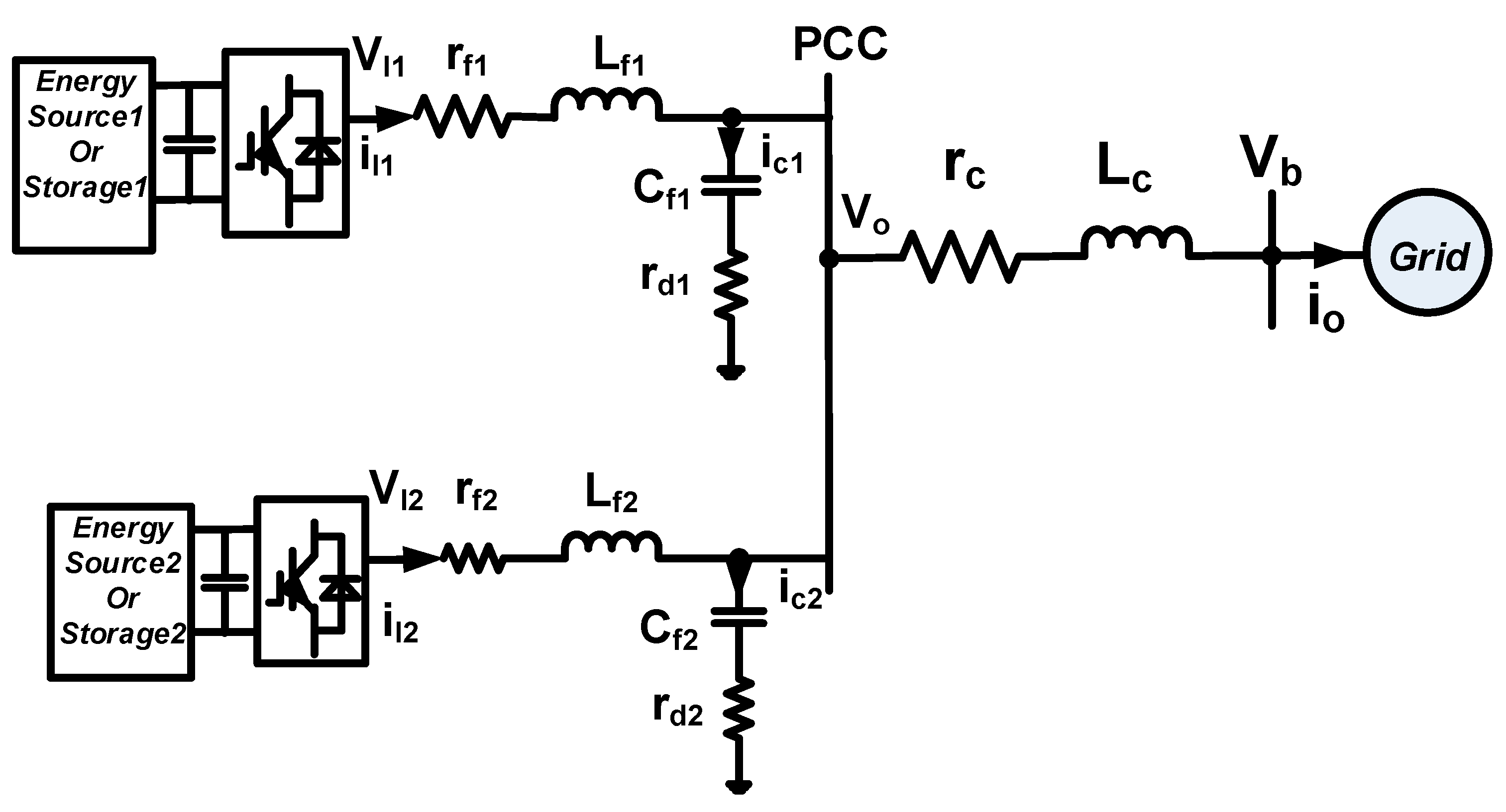
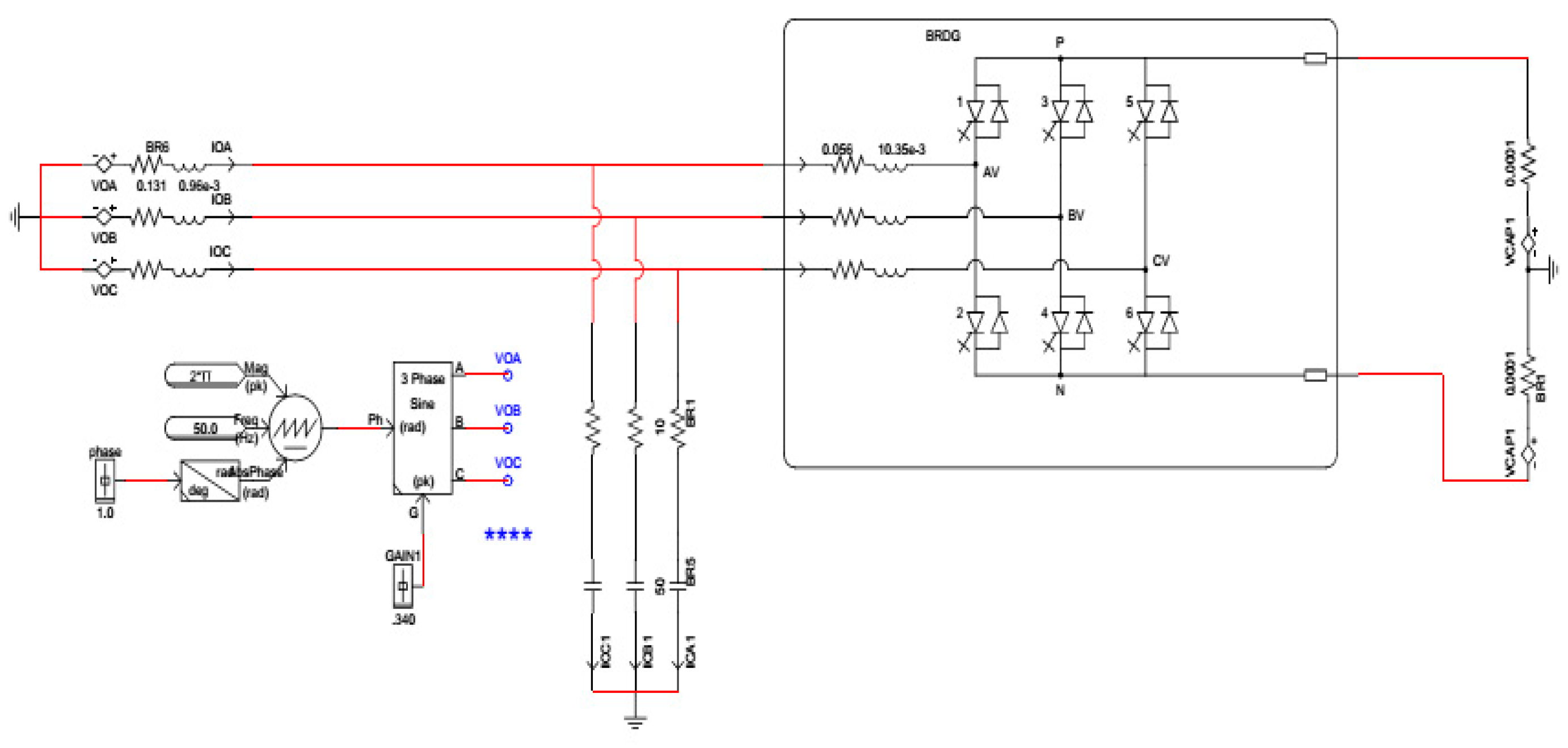
2. System Description

Microgrid is defined as one or more DG units connected closely with loads through coupling inductance and LC filter [3]. DGs such as PV generate DC power therefore; they usually utilize an inverter to convert the DC power to AC. Microgrid operates in two different modes; island and grid-connected modes. In the island or autonomous mode, maintaining the voltage and frequency of the system and supporting the required active and reactive powers is the main task [27,28,29,30,31]. In the grid-connected mode, the main target is to control the delivered DGs powers into the grid. In this paper, to control a predefined real and reactive powers to the grid, two cases are considered. In the first case, an inverter-based DG is delivering power to the grid through a coupling inductance and LC filter as shown in Figure 1. While in the second case, two inverter-based DG units are sharing their powers to the grid at the point of common coupling (PCC) through a coupling inductance and LC filter as shown in Figure 2.
From Figure 1 and Figure 2:
  • Cf, Lf and Rf are the capacitance, inductance and resistance of the LC filter,
  • Lc and Rc are the inductance and resistance of the coupling inductor,
  • Rd is the damping resistance,
  • iL is the coupling inductor current,
  • io is the inverter output current,
  • ic is the capacitor current,
  • VI is the inverter output voltage,
  • Vo is the PCC voltage,
  • Vg is the grid voltage.
  • Cf1, Lf1 and rf1 are the capacitance, inductance and resistance of the LC filter for DG1,
  • Cf2, Lf2 and rf2 are the capacitance, inductance and resistance of the LC filter for DG2,
  • iL1 and iL2 are the coupling inductor currents of DG1 and DG2 respectively,
  • ic1 and ic1 are the capacitor currents of DG1 and DG2 respectively,
  • VI1 and VI2 are the inverter output voltages of DG1 and DG2 respectively,
  • rd1 and rd2 are the damping resistances.
In both cases, it is worth mentioning that each DG inverter is assumed to be connected to a constant DC power source, so there no need to regulate the DC-link voltage otherwise, a controller should be introduced to regulate the DC-link voltage [13]. Meanwhile, our main objective in this paper is to study the AC side dynamic performance of the inverter-based DG in the grid-connected mode.

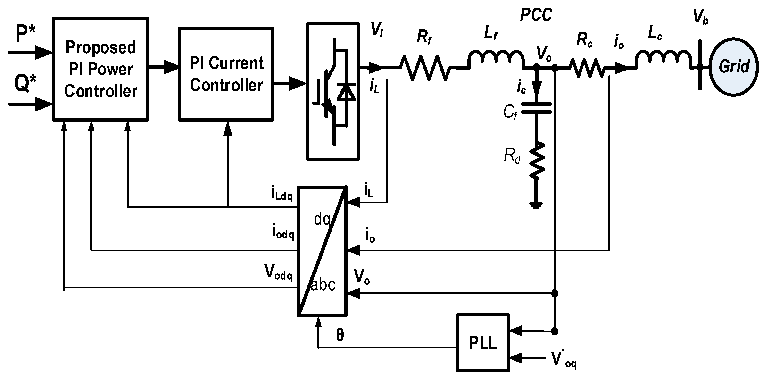
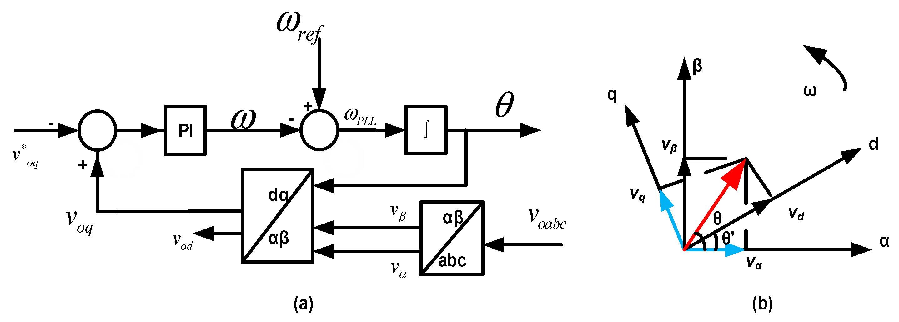
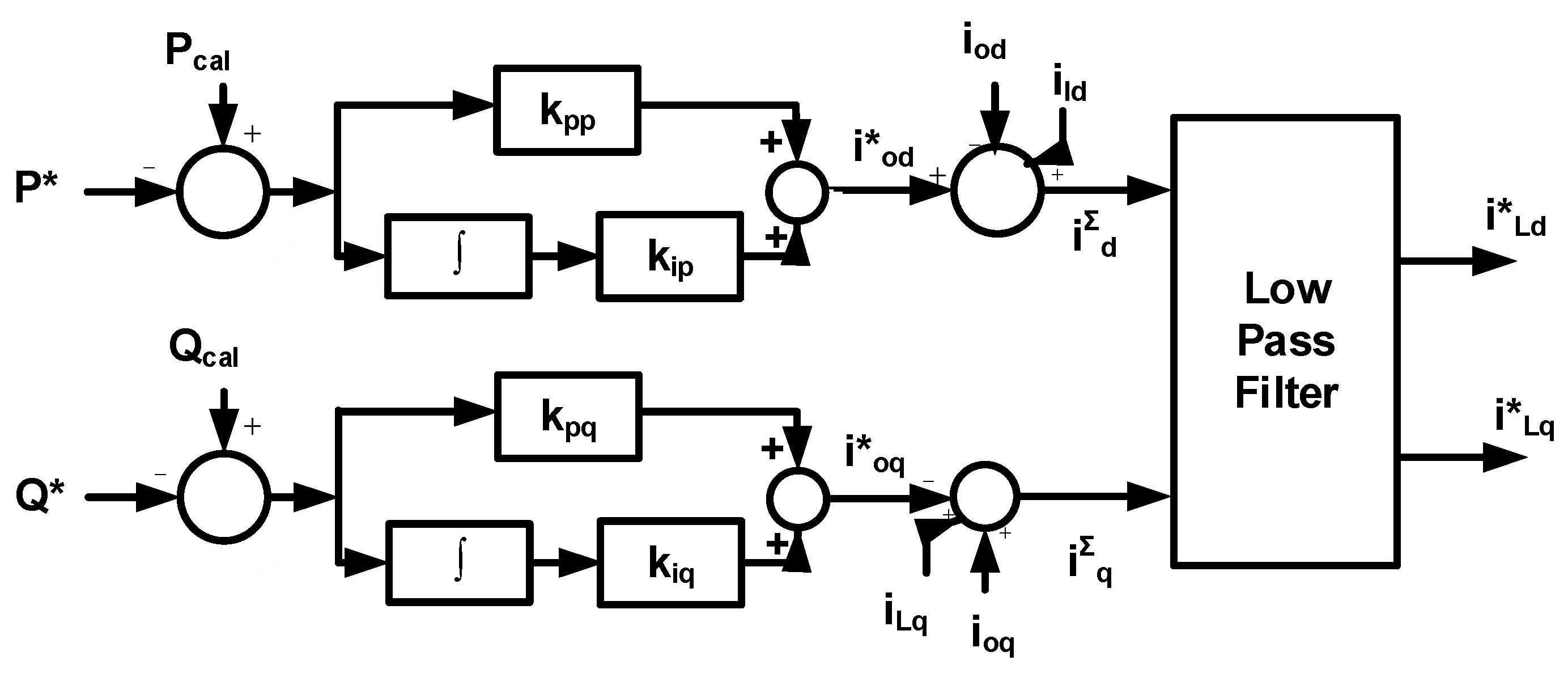
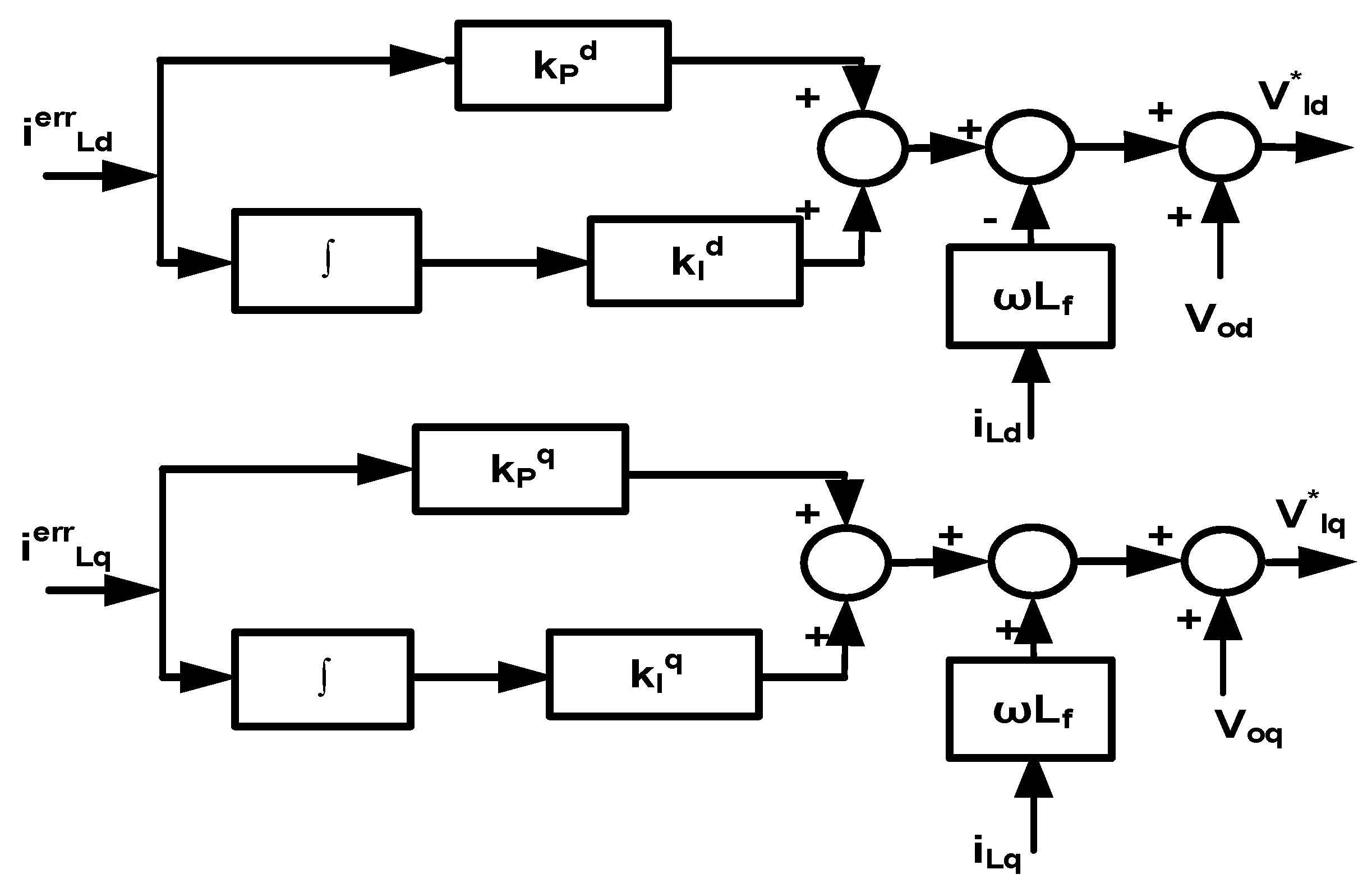
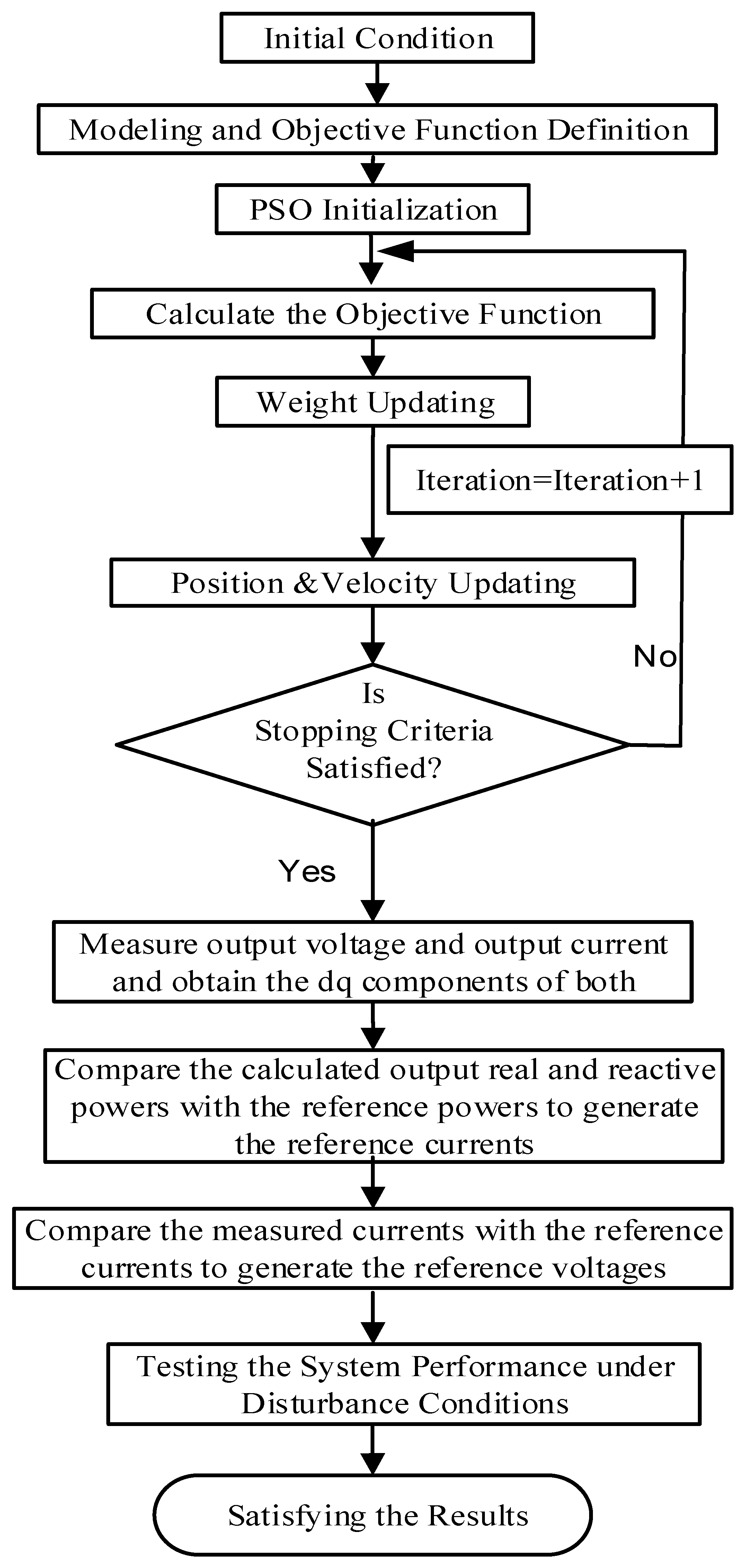
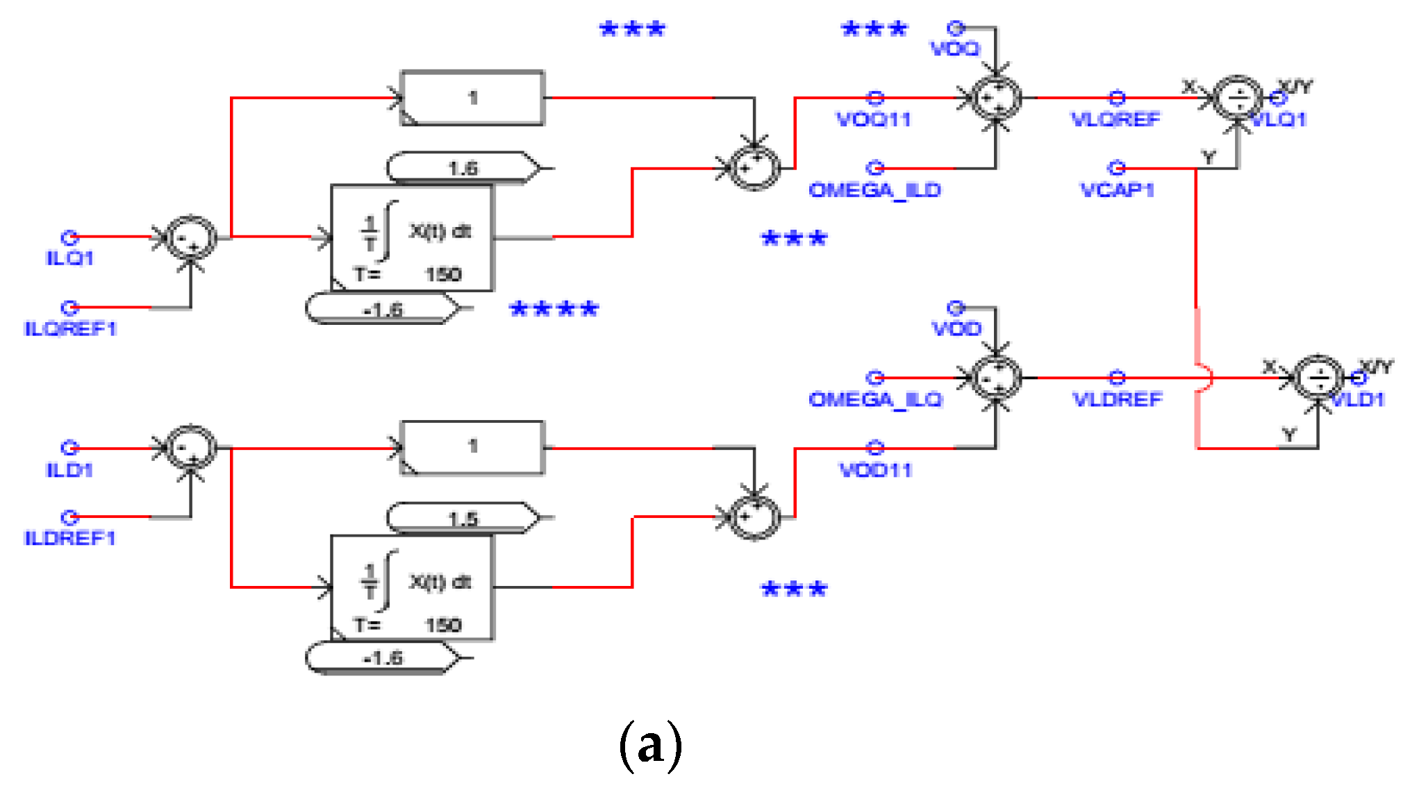
3. Proposed Methodology

Depending on the grid demand, the DG inverter is controlled to inject specific amount of power. An optimal PQ control scheme illustrated in Figure 3 is proposed adopting double loop controls to improve the dynamic performance of the grid-connected microgrid. The proposed PI power controller is firstly implemented to produce the reference current signal based on injected power. Secondly, the current control loop considers several aspects such as providing injected three-phase balanced currents, obtaining high power quality and overcoming the nonlinearities coming from the interaction between inverter switching and external disturbances [21].
The proposed methodology can be summarized as follows. Firstly, the optimization process will be initiated where PSO generates random controller parameters. These random parameters are used to calculate the objective function. The minimum objective function and its corresponding optimal parameters will be saved. Secondly, the inverter output voltage and current are measured and converted into dq forms. Thirdly, the real and reactive powers are calculated using the output voltage and current. Fourthly, the optimal controller parameters of the power controller are used to generate the reference currents by comparing the calculated powers with reference powers. Finally, the optimal controller parameters of the current controller are employed to generate the reference voltages to fire the inverters by comparing the reference currents with measured currents. These steps will be explained in detail in the next sections.
Firstly, the three-phase output voltage vo and current io are measured at PCC as shown in Figure 1 and Figure 2. Then the measured output voltage vo is converted to the dq components using the transformation angle θ as given in Equation (1). Similarly, the dq components of the output current io can be obtained. The angle θ is obtained using the phase locked loop (PLL) shown in Figure 4a,b. Considered as one of the most common synchronization methods, PLL is used to extract the phase angle θ of the grid voltage and keep the output signal synchronized with the frequency and phase of the reference input signal [31].
( v o d v o q v o o ) = 2 3 ( cos θ cos ( θ 2 π 3 ) cos ( θ + 2 π 3 ) sin θ sin ( θ 2 π 3 ) sin ( θ + 2 π 3 ) 1 2 1 2 1 2 ) ( v o a v o b v o c )
ω = k P P L L ( v o q v o q ) + k I P L L ( v o q v o q ) d t
θ = ( ω ω r e f ) d t + θ ( 0 )
where ω and ωref are the nominal and reference frequencies, voq and v*oq are the q components of the inverter output and reference voltages vo and v*o, kPPLL, kIPLL are the PI controller parameters of the PLL.
Secondly, the dq components of the output voltage and current are used to calculate the real and reactive powers (Pcal and Qcal) as given in [3].
P cal = v o d i o d + v o q i o q
Q cal = v o d i o q v o q i o d
where vod and voq are the dq components of the inverter output voltage vo, iod and ioq are the dq components of the inverter output current io.
Thirdly, by comparing the reference real and reactive powers (P* and Q*)and the calculated real and reactive powers (Pcal and Qcal) respectively, the proposed PI power controller is deployed to produce the dq components of the output reference currents (i*od and i*oq) as given in Equations (6) and (7). The injected powers to the grid could track the reference power. Note that real and reactive power can be controlled independently because of the decoupling of the reference current (6) and (7) as shown in Figure 5.
i o d = k p p ( P P c a l ) + k i p ( P P c a l ) d t
i o q = k p q ( Q Q c a l ) + k i q ( Q Q c a l ) d t
where kpp, kip, kpq and kiq are the PI power controller parameters.
The inverter is controlled to inject the coupling inductor current iL not the inverter output current io as shown in Figure 1 and Figure 2. Therefore, to obtain the coupling inductor reference current iL in the dq frame, the dq components of the output reference currents i*o is added to the dq components of the capacitor current ic as given in Equations (8) and (9) and shown in Figure 5.
i d Σ = i o d + i c d = i o d + ( i L d i o d )
i q Σ = i o q + i c q = i o q + ( i L q i o q )
Then the fundamental reference currents i*Ld and i*Lq can be obtained using a low-pass filter [21].
i L d = ω c 2 s 2 + 2 s ω c + ω c 2 i d Σ
i L q = ω c 2 s 2 + 2 s ω c + ω c 2 i q Σ
where ωc is the cut-off frequency of the low-pass filter.
Fourthly, the PI current controller shown in Figure 6 is used to obtain the dq components of the reference voltage v*l targeting zero steady state error and compensating both inductor non-idealities and inverter switching nonlinearities [21].
v l d = v o d ω L f i L d + k P d ( i L d i L d ) + k I d ( i L d i L d ) d t
v l q = v o q + ω L f i L q + k P q ( i L q i L q ) + k I q ( i L q i L q ) d t
where iLd, iLq are dq components of the coupling inductor current iL, i*Ld, i*Lq are dq components of the reference controller current i*L, kPd, kId, kPq, kIq are PI current controller parameters.
Additionally, the relationship between the PCC output voltage vo and the inverter voltage vl are given by Equations (14), (15), and (16) [32].
[ v l a v l b v l c ] = R f [ i l a i l b i l c ] + L f d d t [ i l a i l b i l c ] + [ v o a v o b v o c ]
v l d = v o d + R f i o d + L f d i o d d t ω L f i o q
v l q = v o q + R f i o q + L f d i o q d t + ω L f i o d
To reduce the inverter switching frequency ripple, a low-pass filter is used. Additionally, a damping resistance is added to evade the possible resonance between this filter and the coupling inductance shown in Figure 1 [21]. Their models are given as follows:
v l a = i L a R f + L f d i L a d t + v C a + i C a R d
v b a = i o a R c L c d i o a d t + v C a + i C a R d
d v C a d t = 1 C f ( i L a i o a )
where vLa, vLb, vLc are inverter output voltages.

4. Optimal Controller Design

Based on time domain simulation, the control problem is designed and formulated as an optimization problem where PSO is employed to minimize the proposed objective function J aiming to obtain the optimal controller and filter parameters [3].
J = t = 0 t = t s i m ( P c a l P * ) 2 . t   d t
where t is added to ensure minimum settling time, tsim the simulation time, and Pcal and P* are the calculated and reference real power of the inverter-based DG respectively.
The problem constraints are the controller and filter parameters K= [kpp kipkpqkiqkpd kidkpqkiqLfCf, Rd] T bounded as follows:
K min K K max
where kpp kipkpq and kiq are the PI controller parameters of the proposed power controller while kpd kidkpq and kiq are the PI controller parameters of the current controller. Lfa and Cf are the filter inductance and capacitance respectively. Rd is the damping resistance.
In 1995, PSO is a population based stochastic optimization method developed by Eberhart and Kennedy inspired by social behavior of bird flocking or fish schooling [33]. It is worth mentioning that PSO is used as an efficient tool for optimization that gives a balance between local and global search techniques. PSO advantages—like computational efficiency, simplicity, and robustness—will enhance the microgrid transient performance [3]. Using PSO, the best solution (candidate) of the population could be obtained by starting random particles selection and updating the generations inside this population. Ensuring the optimal solution convergence, the particles are moving in the search space trying to follow the optimum particles. In the minimization problem, at a given position, the highest fitness corresponds to the lowest value of the objective function at that position. At iteration (n+1), the new position of each particle is obtained by Equation (22) as follows:
k n + 1 i = k n i + v n + 1 i
where kin+1 is the position of particle i at iteration n+1; kin is the position of particle i at iteration n; and vin+1 is the corresponding velocity vector.
At each time step, the velocity of each particle is modified depending on both current velocity and current distance from the personal and global best positions as follows:
v n + 1 i = w v n i + c 1 r 1 p b e s t k n i + c 2 r 2 ( g b e s t k n i )
where w is the inertia weight; vin is the velocity of particle i at iteration n; r1 and r2 are random numbers between 0 and 1; pbest is the best position found by particle i; gbest is the best position in the swarm at time n; and c1 and c2 are the “trust” parameters. Figure 7 shows the proposed PSO computational flow chart. The PSO steps are summarized in [7].

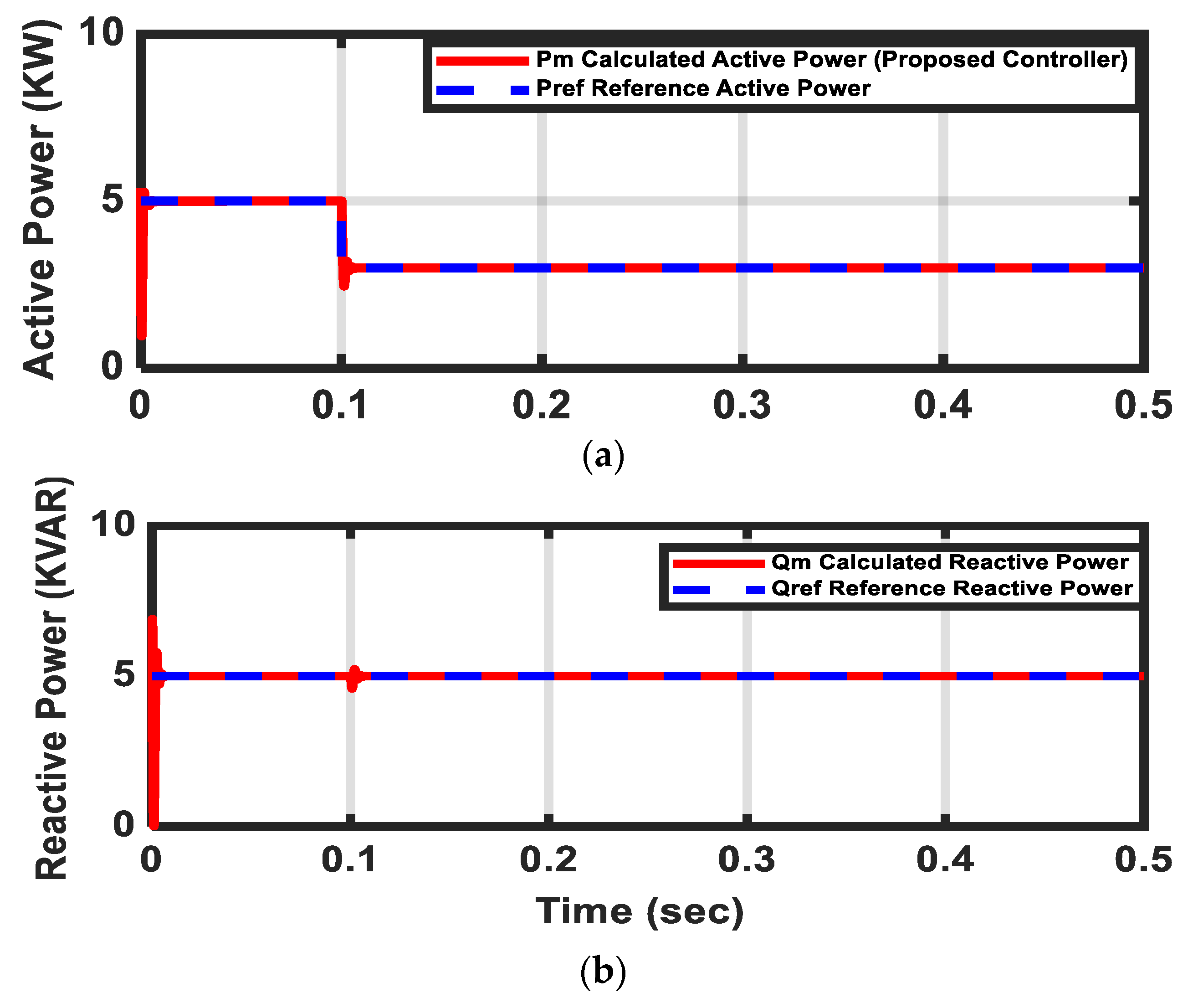
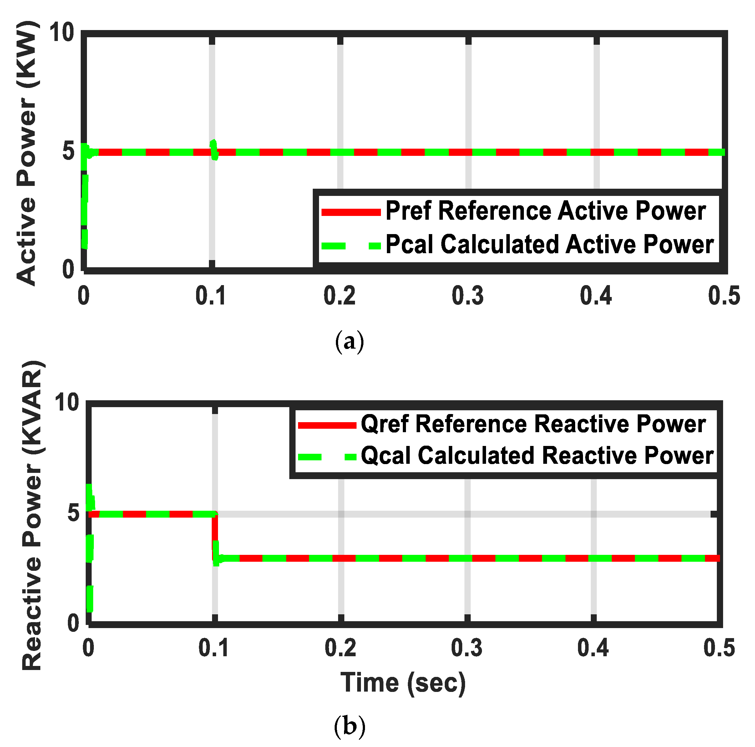
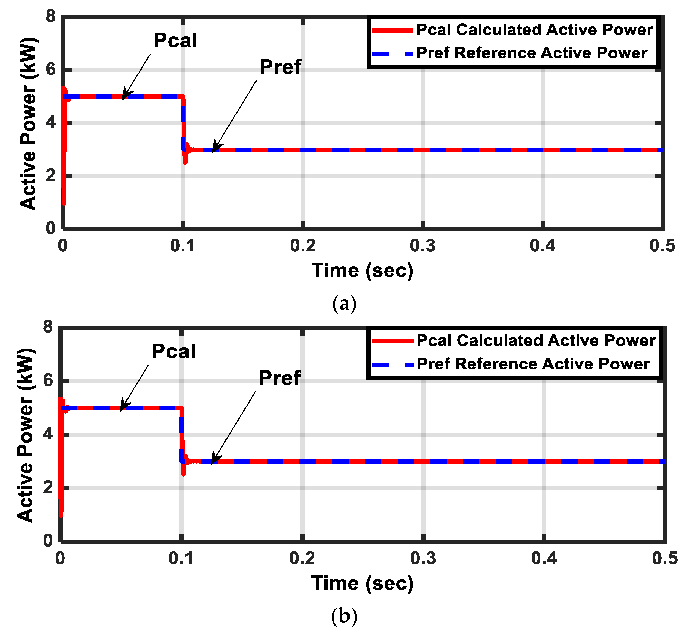
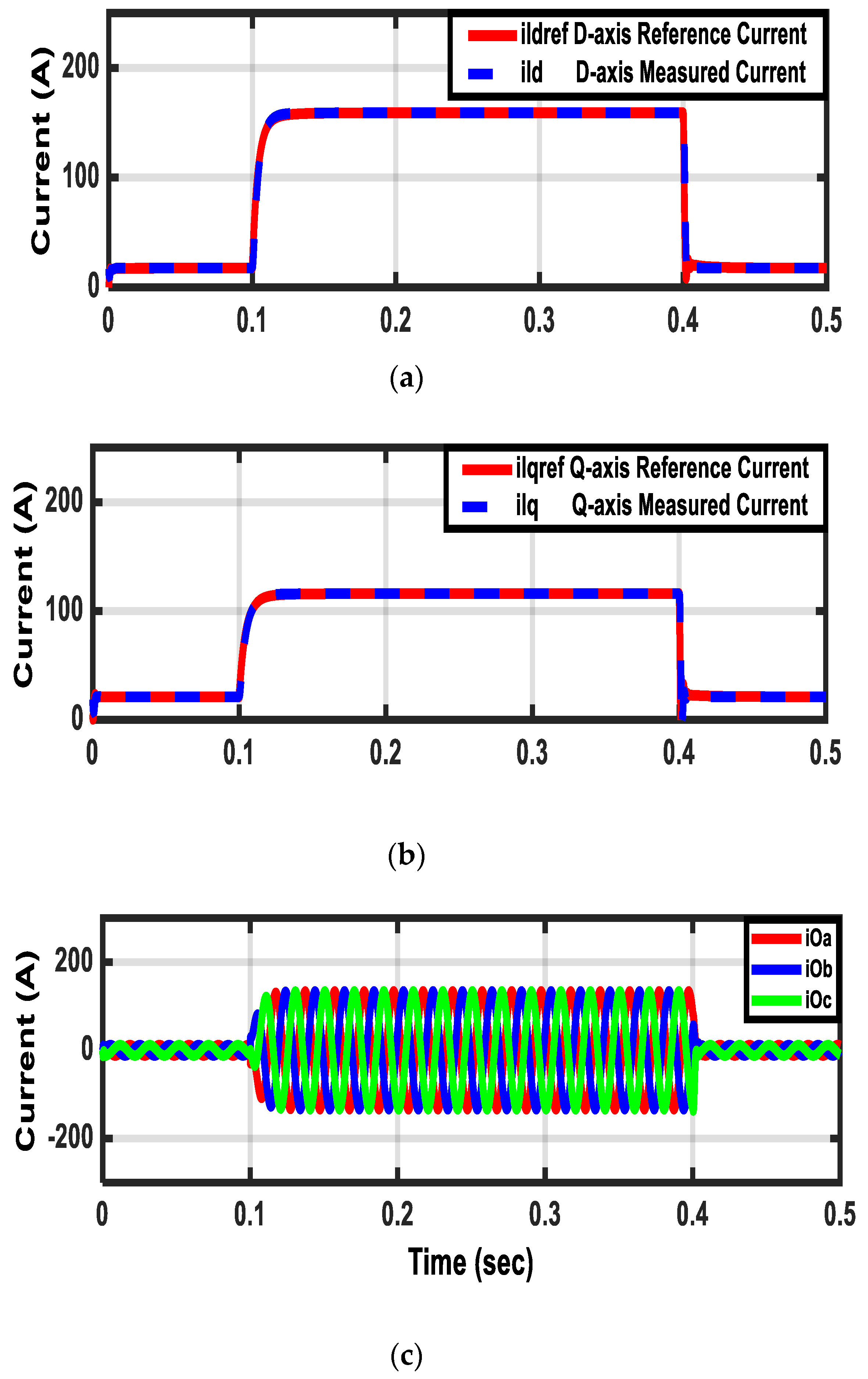
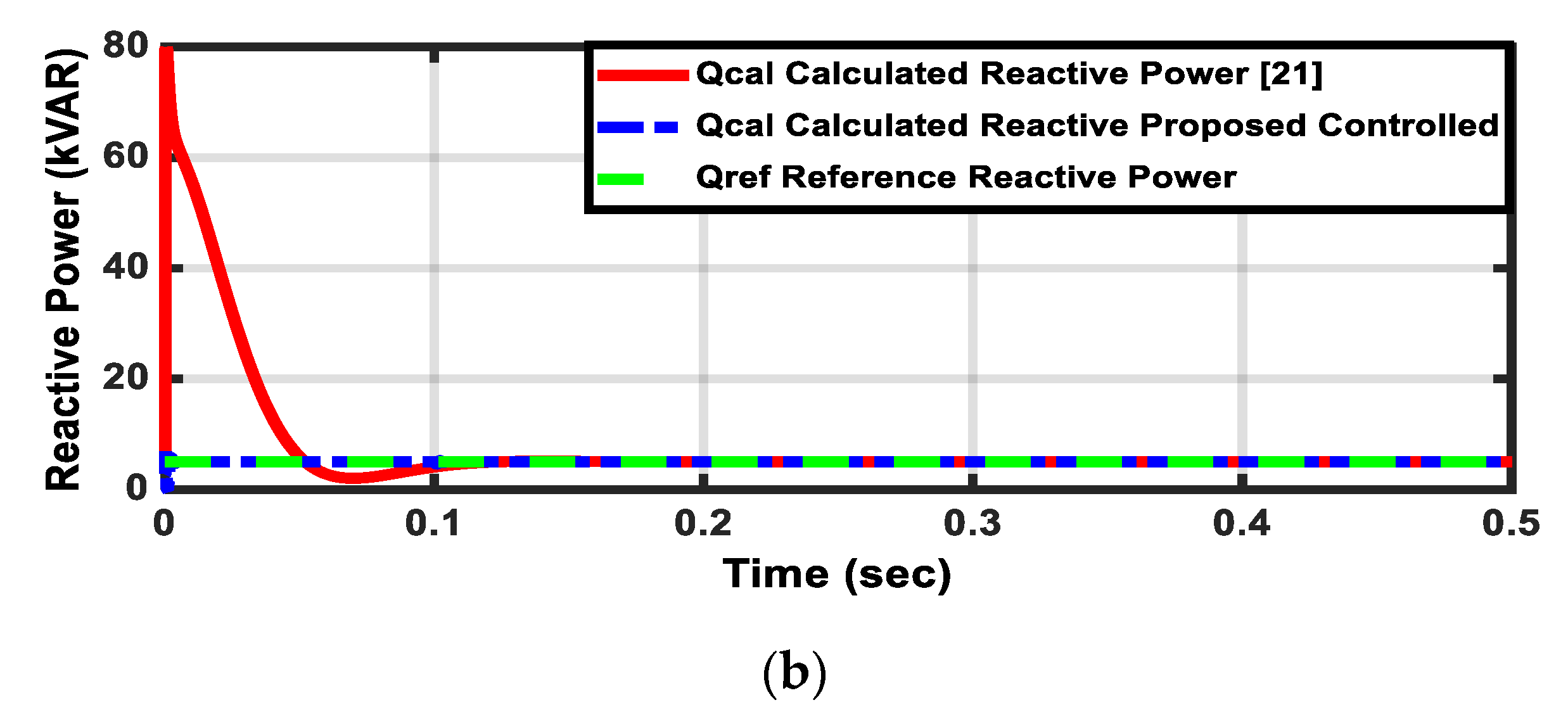
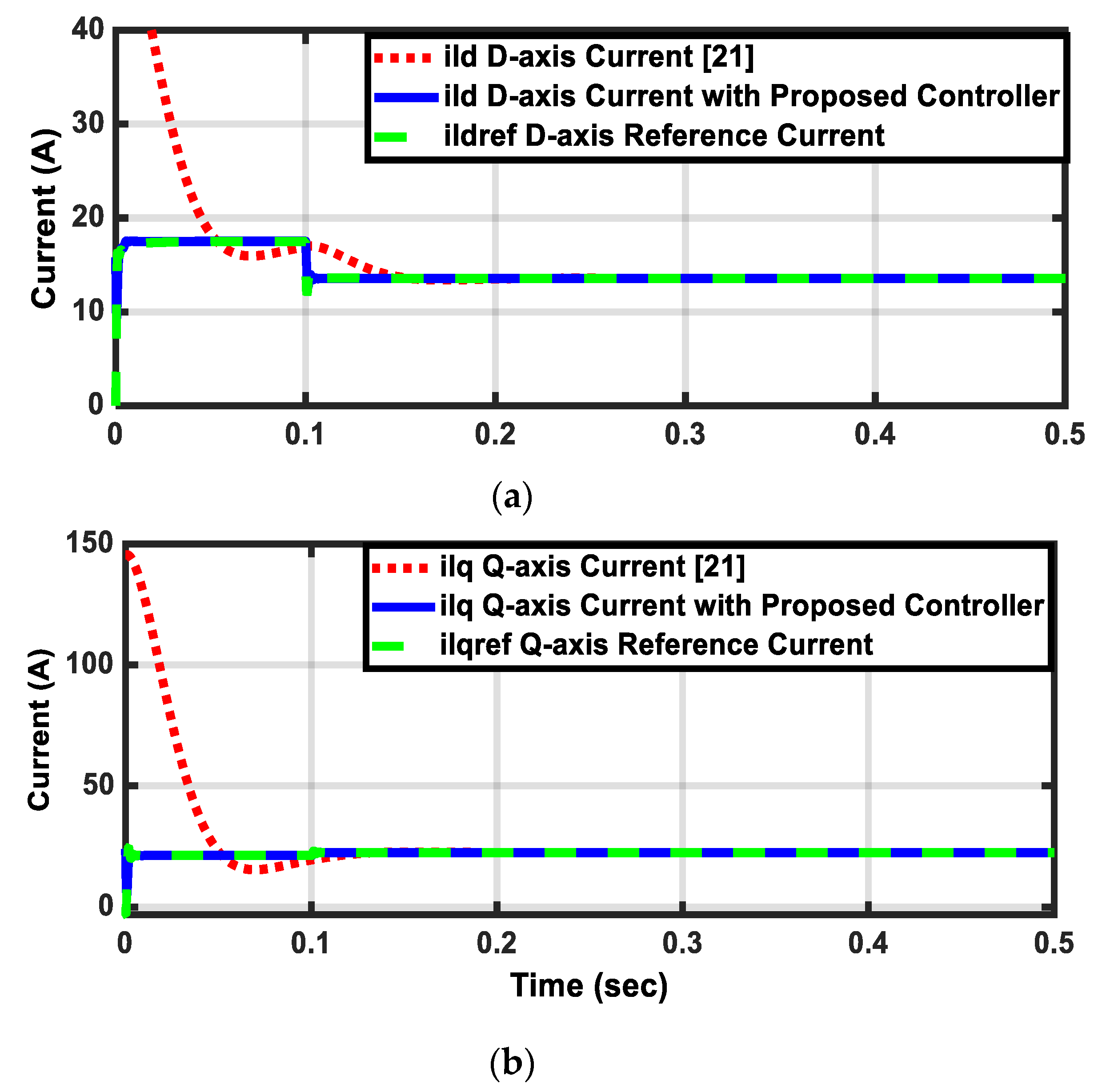
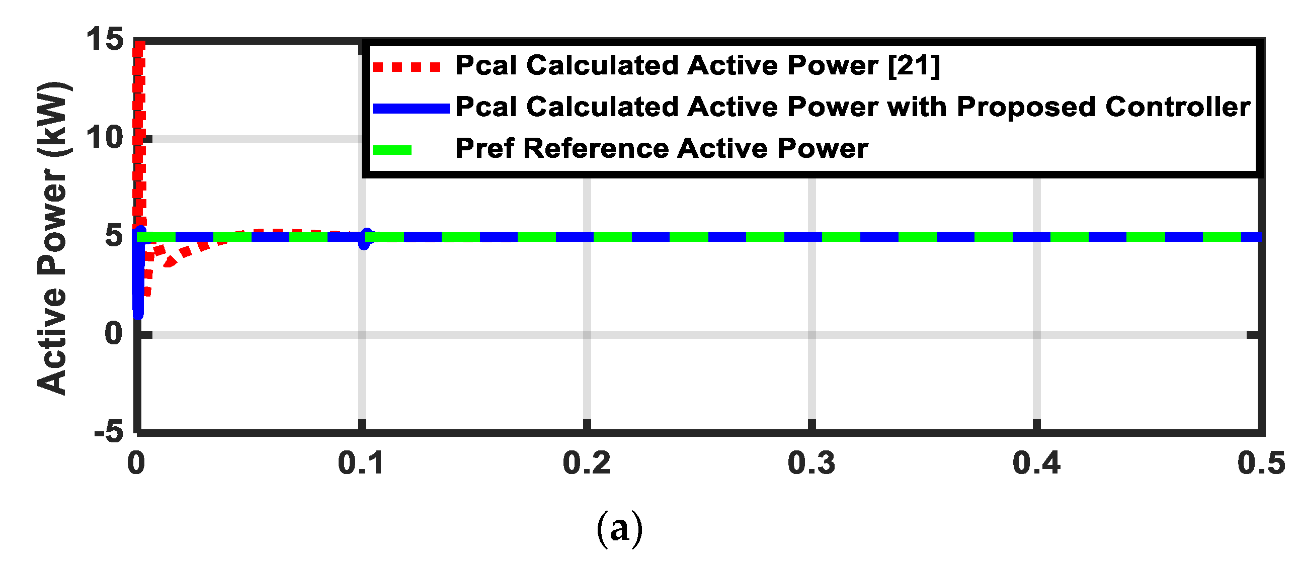
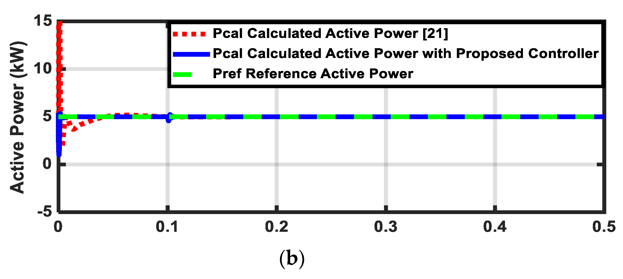
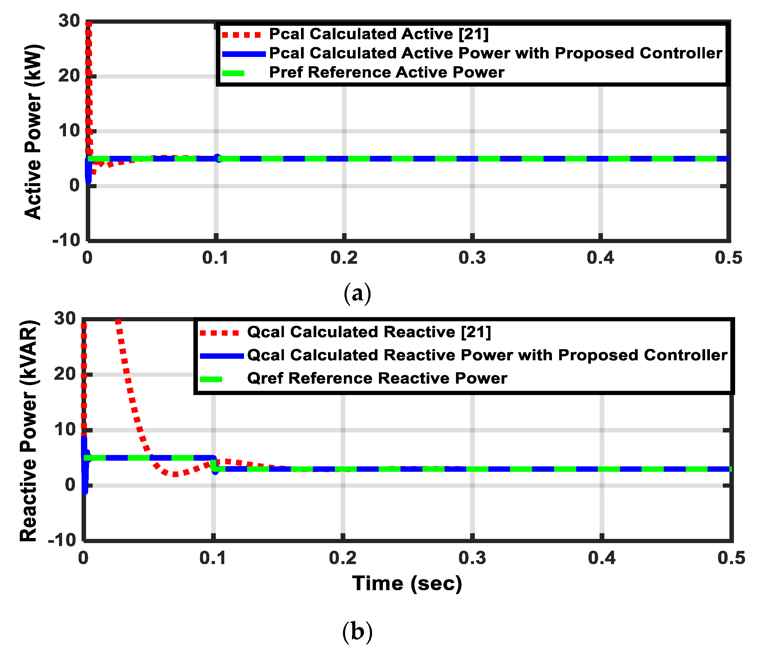
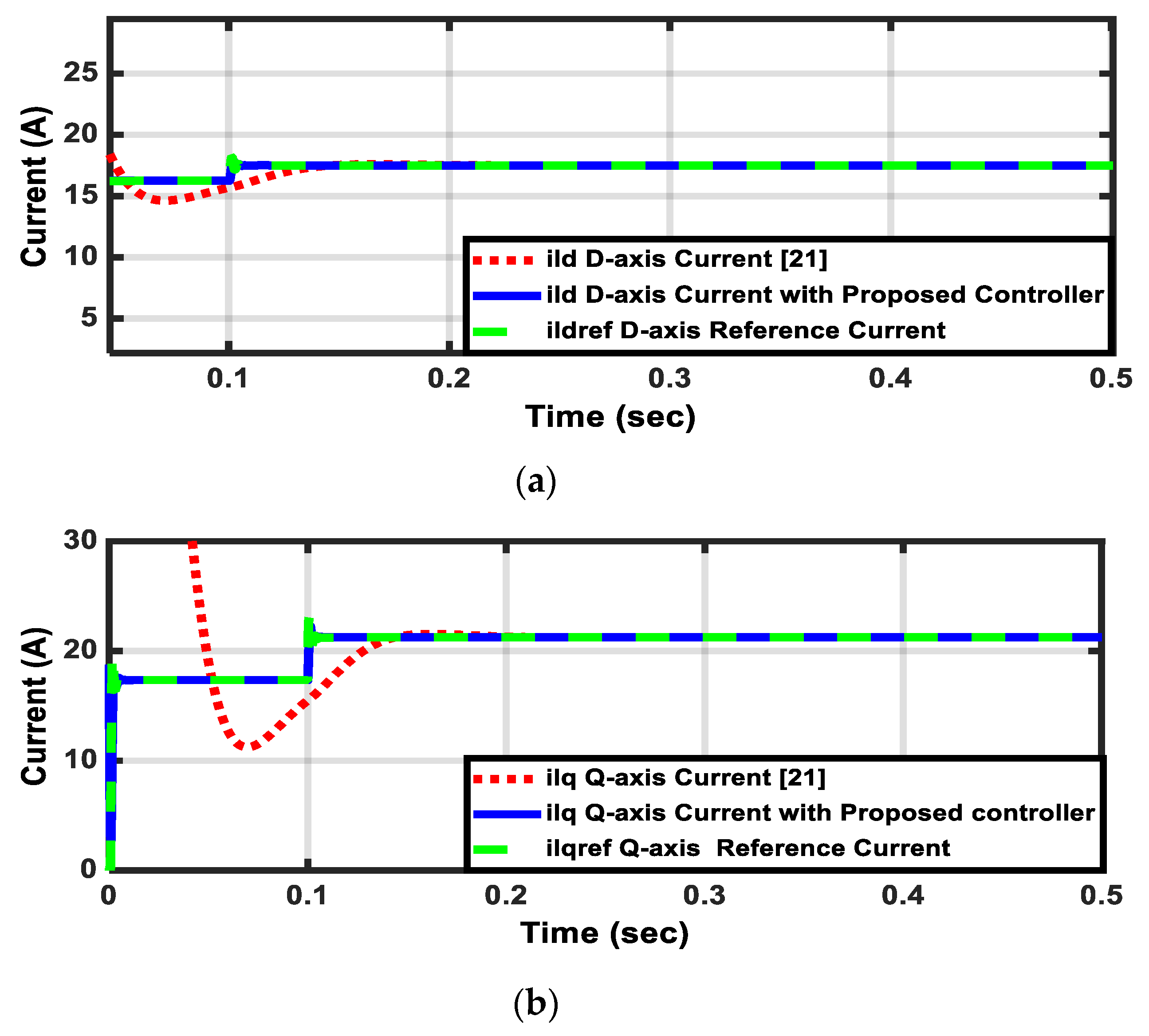
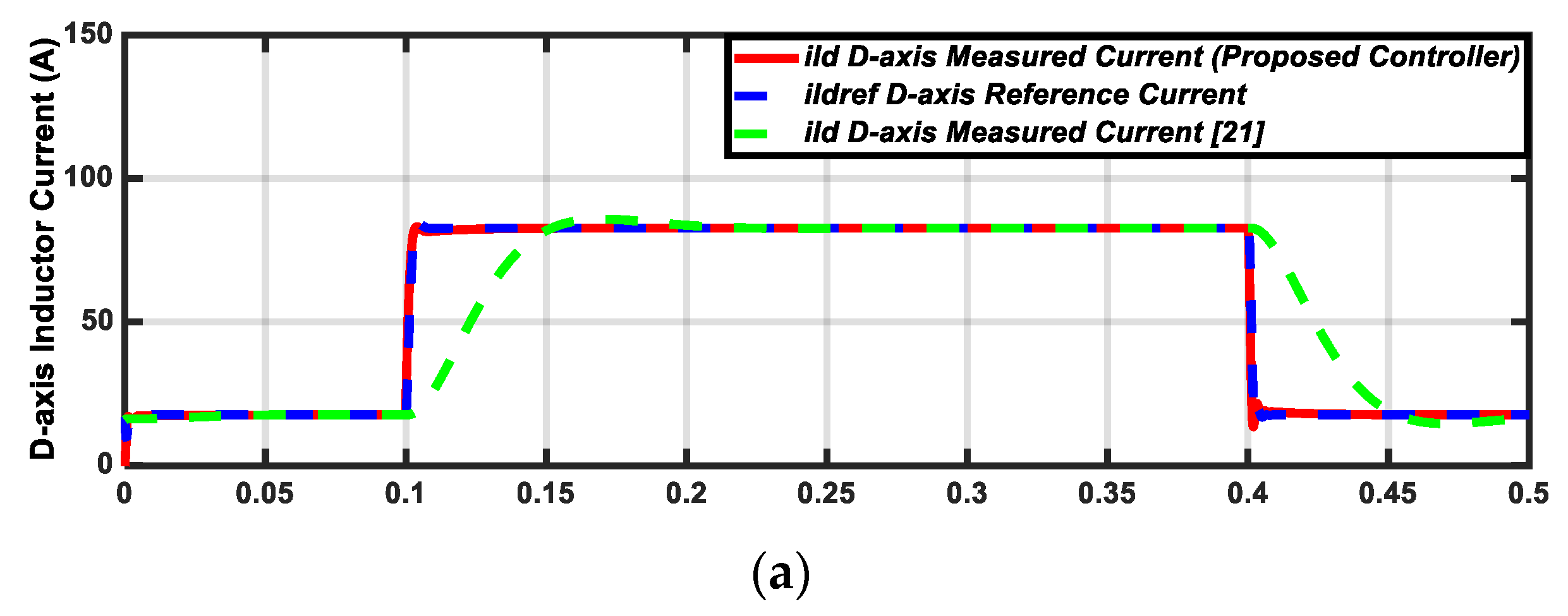
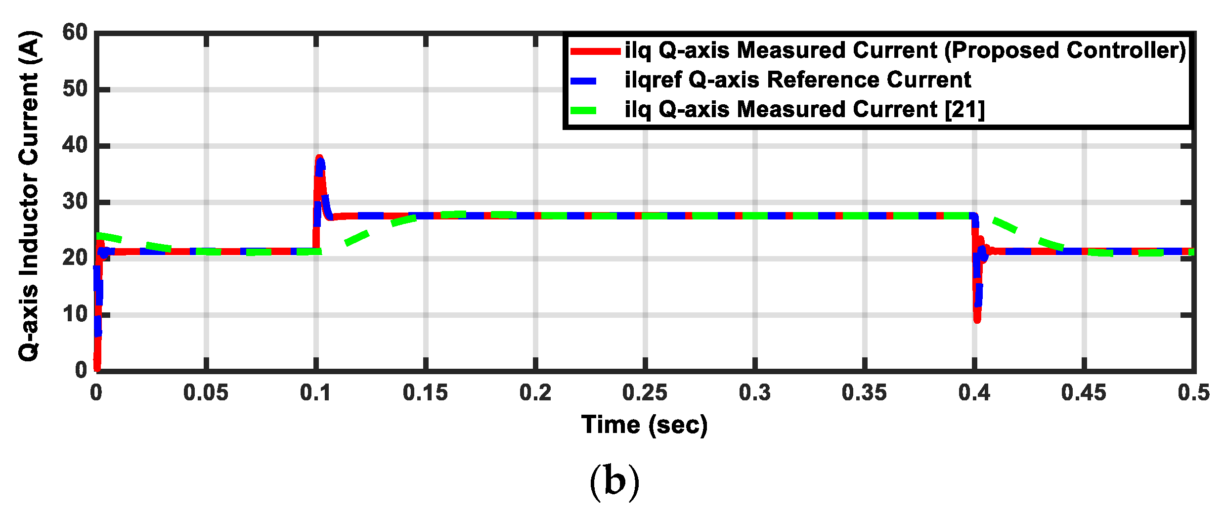
5. Simulation Results and Discussion

In this work, to verify the effectiveness of the PQ control in the grid-connected microgrid, two cases have been simulated. Firstly, 5 kVA inverter-based DG is controlled to deliver a predefined real and reactive powers to the grid. Secondly, two different rated inverter-based DG units (5 kVA and 10 kVA) are sharing their injected controlled powers with the grid. Assuming an ideal source from the DG side, the DC bus dynamics is neglected. With the realization of high switching frequencies (4–10 kHz), the switching process of the inverter may also be neglected [14]. A simulation model for the proposed microgrid cases is built in a MATLAB based on the control strategy. The proportional gain kp and integral gain ki of the power and current controllers have been optimally tuned using PSO. Using the time domain simulation, the microgrid dynamic stability has been investigated and the proposed controller effectiveness has been evaluated under the following different disturbances:
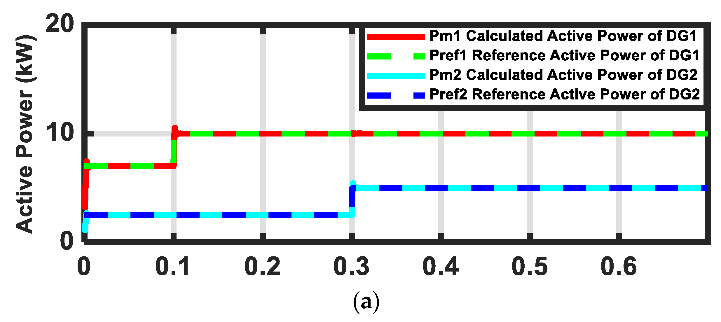
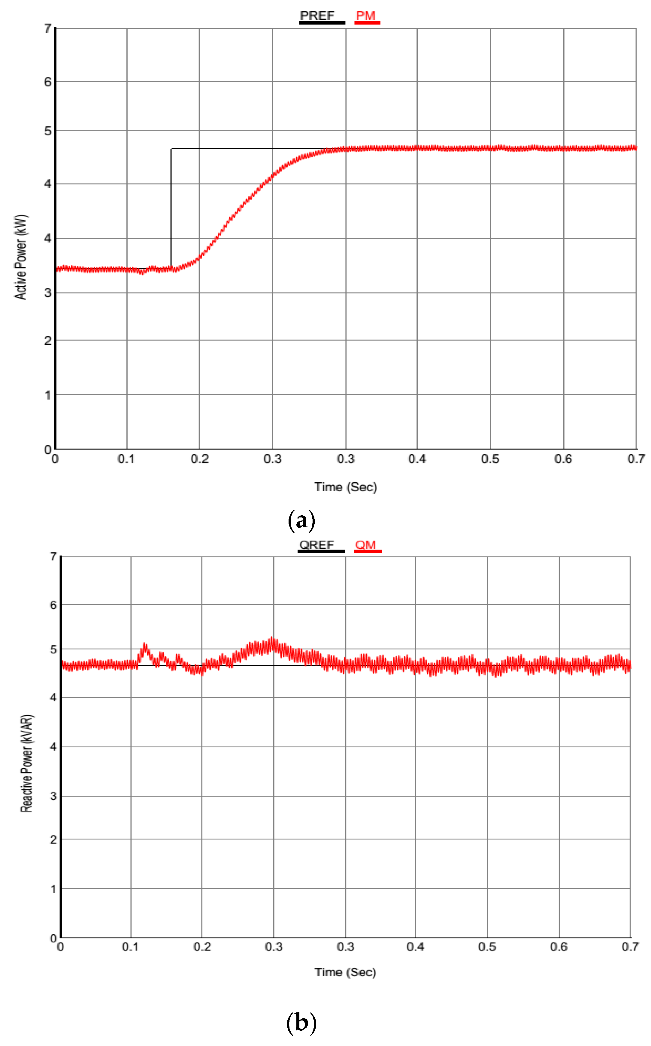
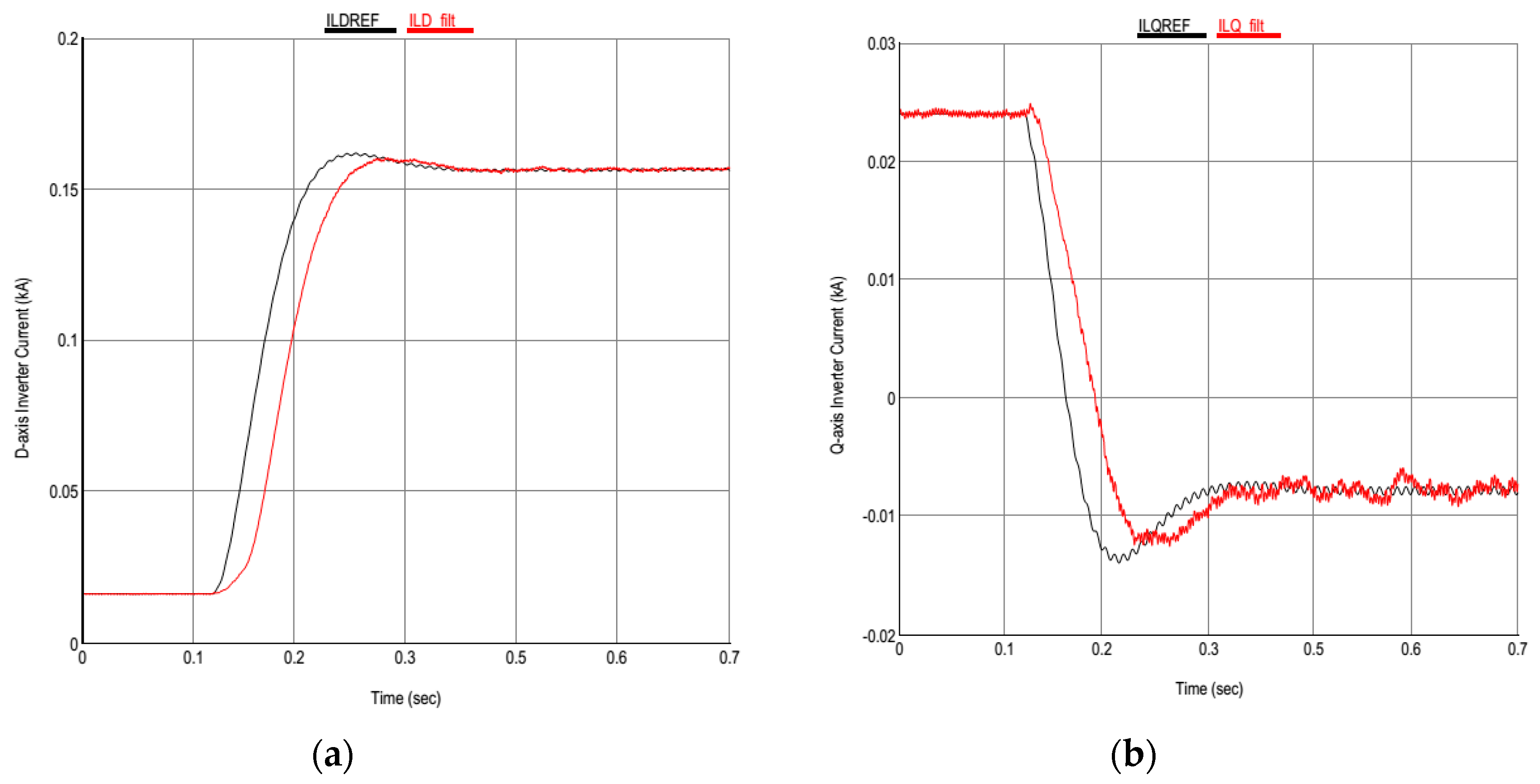
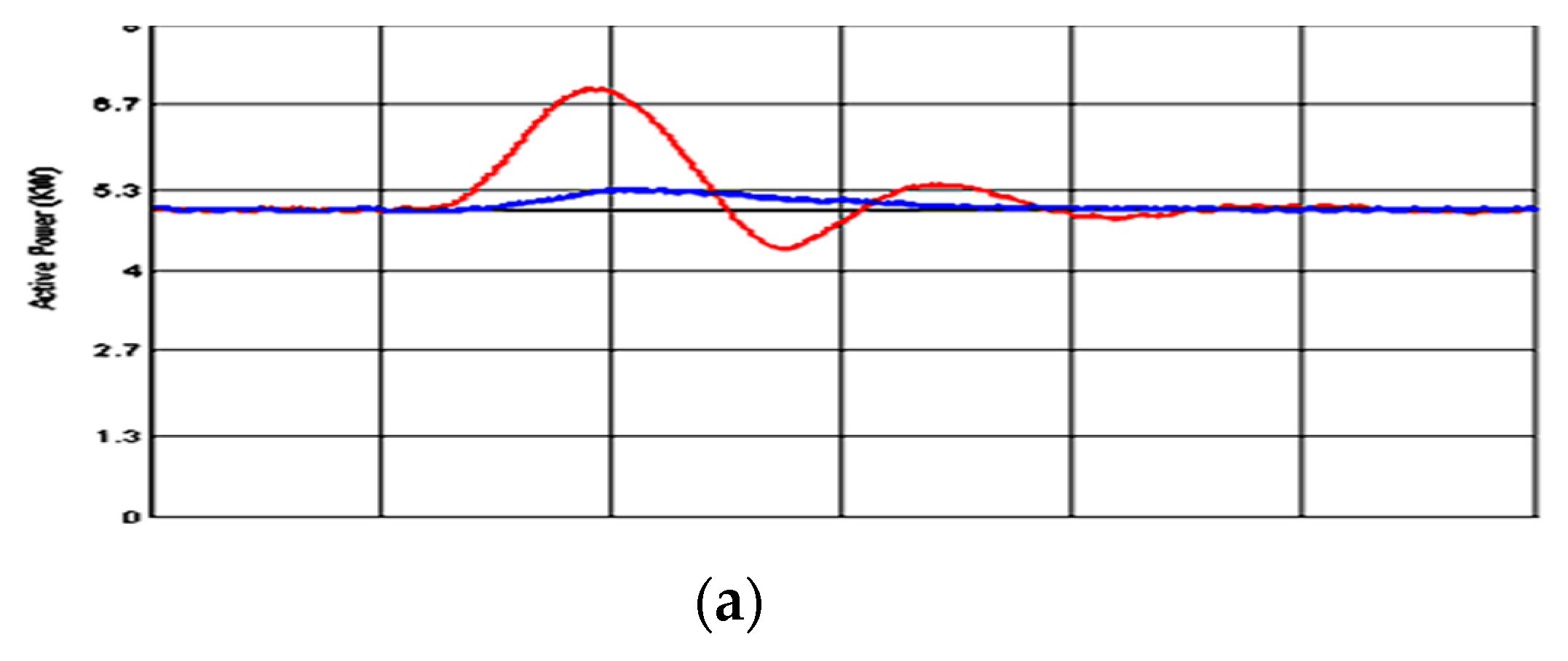
  • Step change in the injected real power.
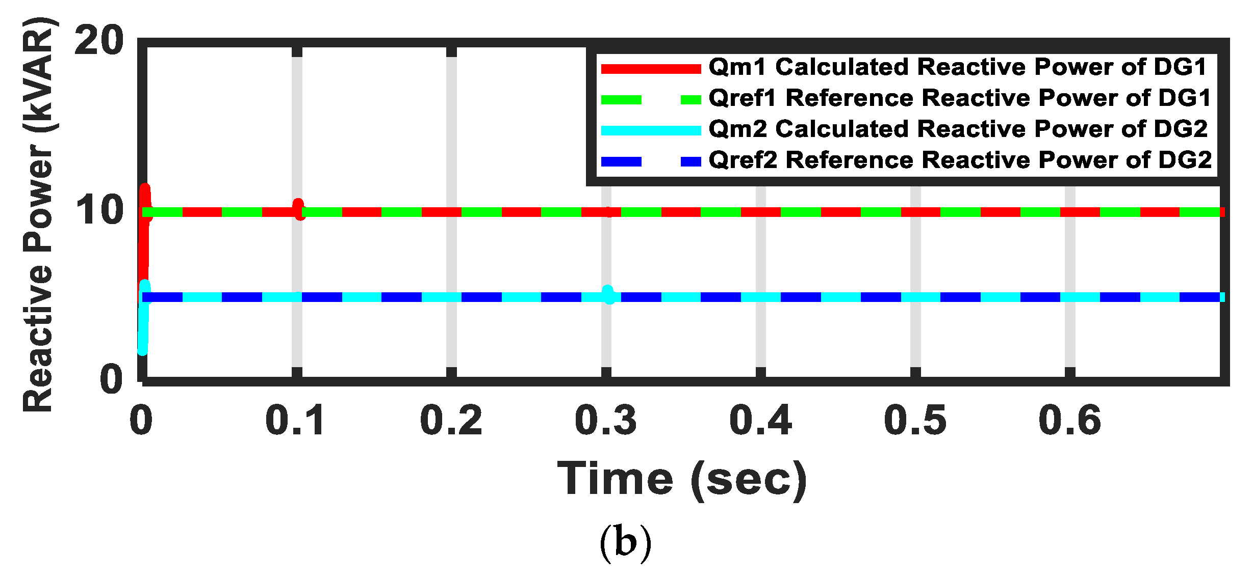
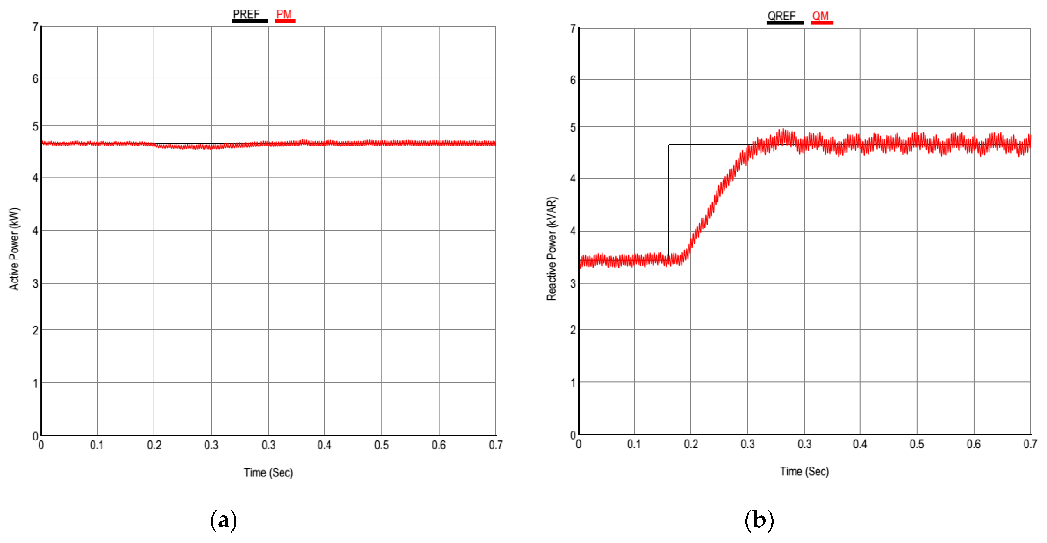
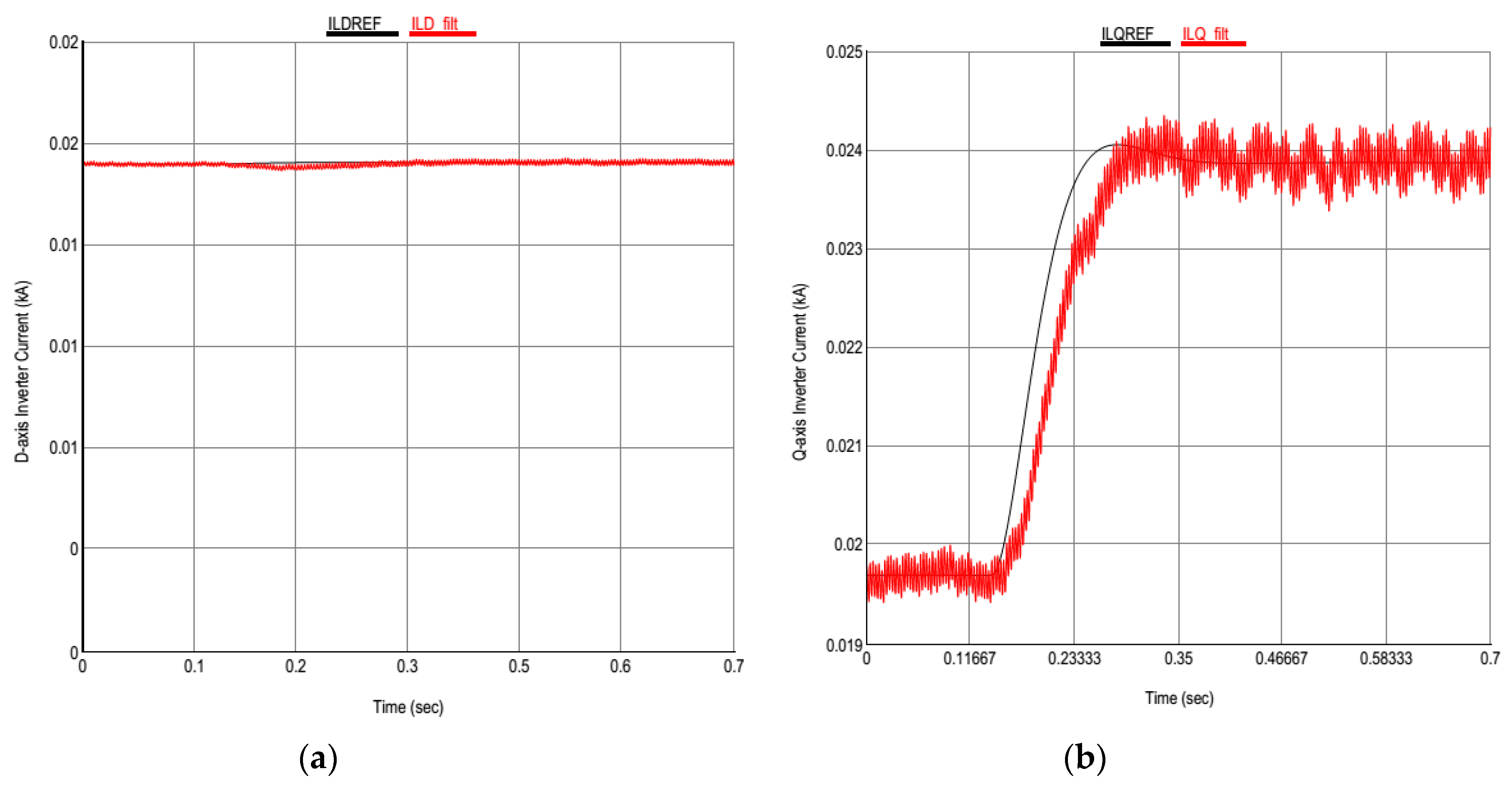
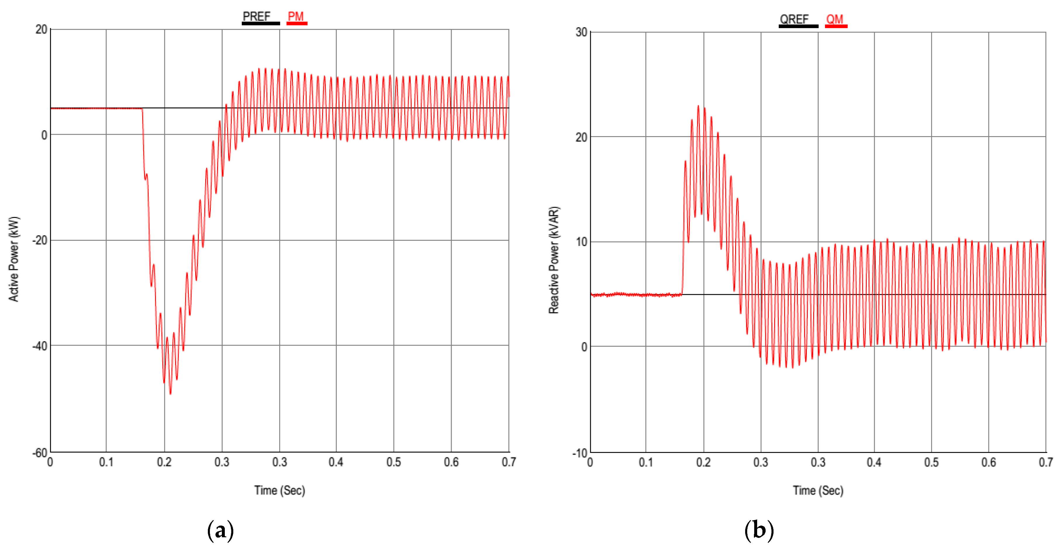
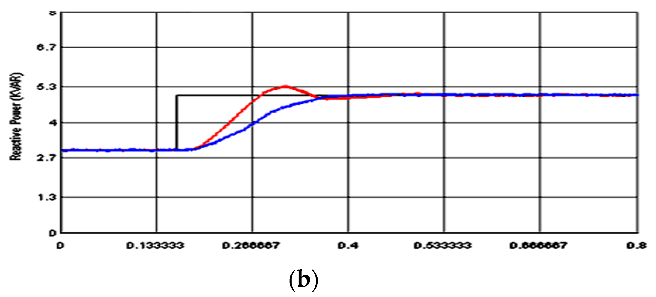
  • Step change in the injected reactive power.
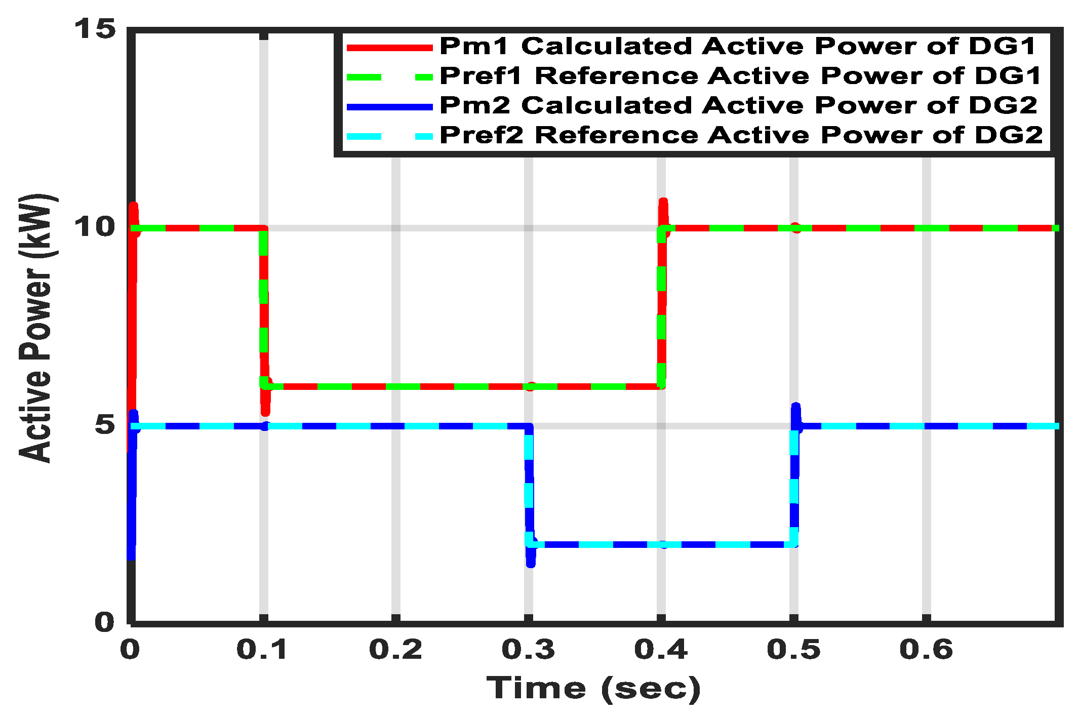
  • Simultaneous step change in both injected real and reactive powers.
  • Three-phase fault at the PCC.
The optimal parameters for both cases are given respectively in Table 1 and Table 2.

5.1. One Inverter-Based DG Case
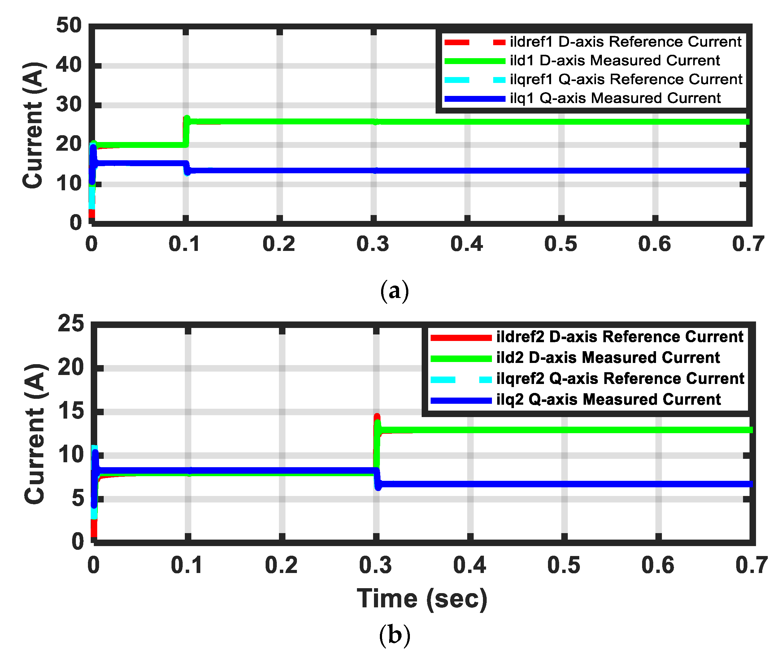
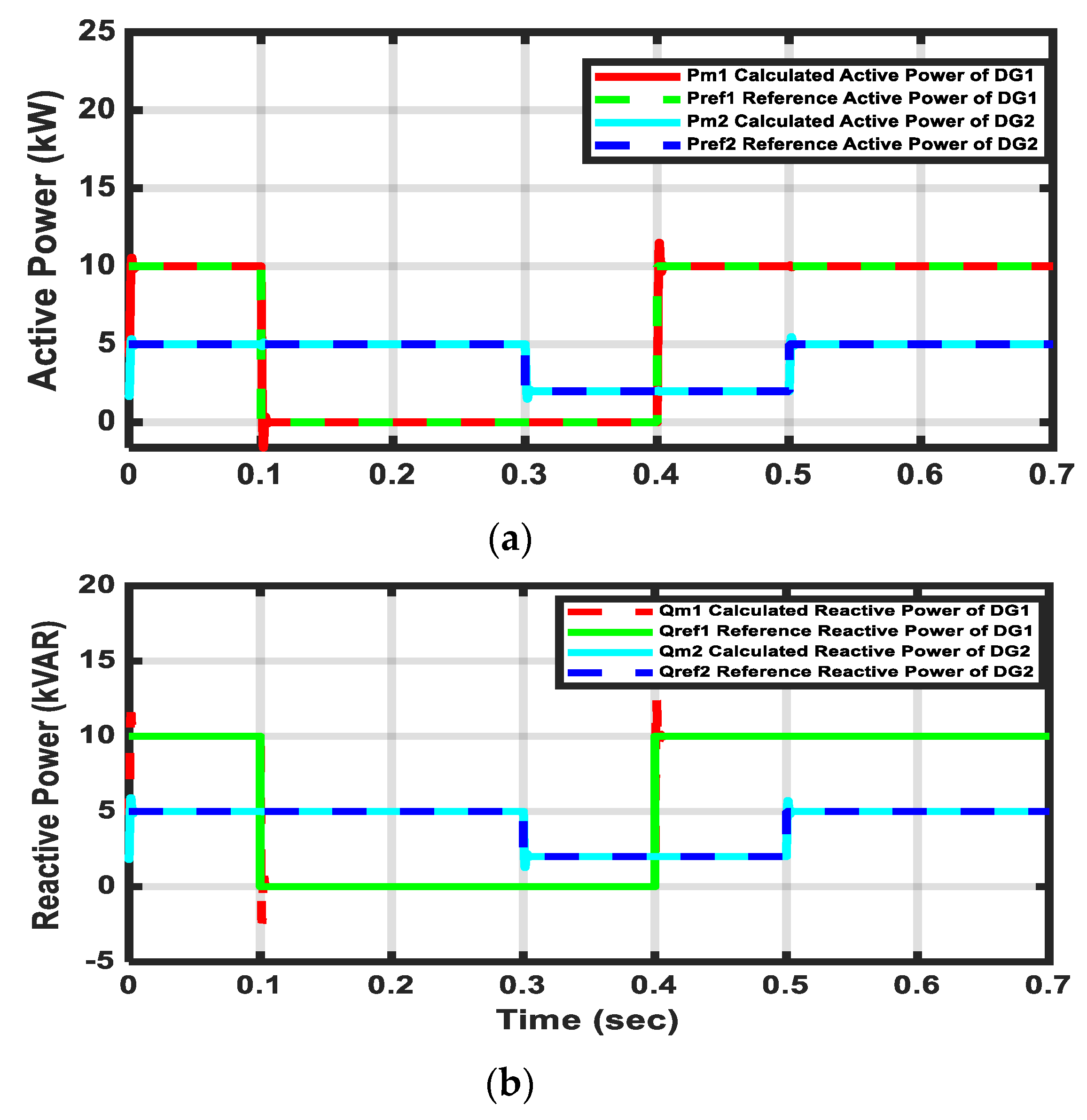
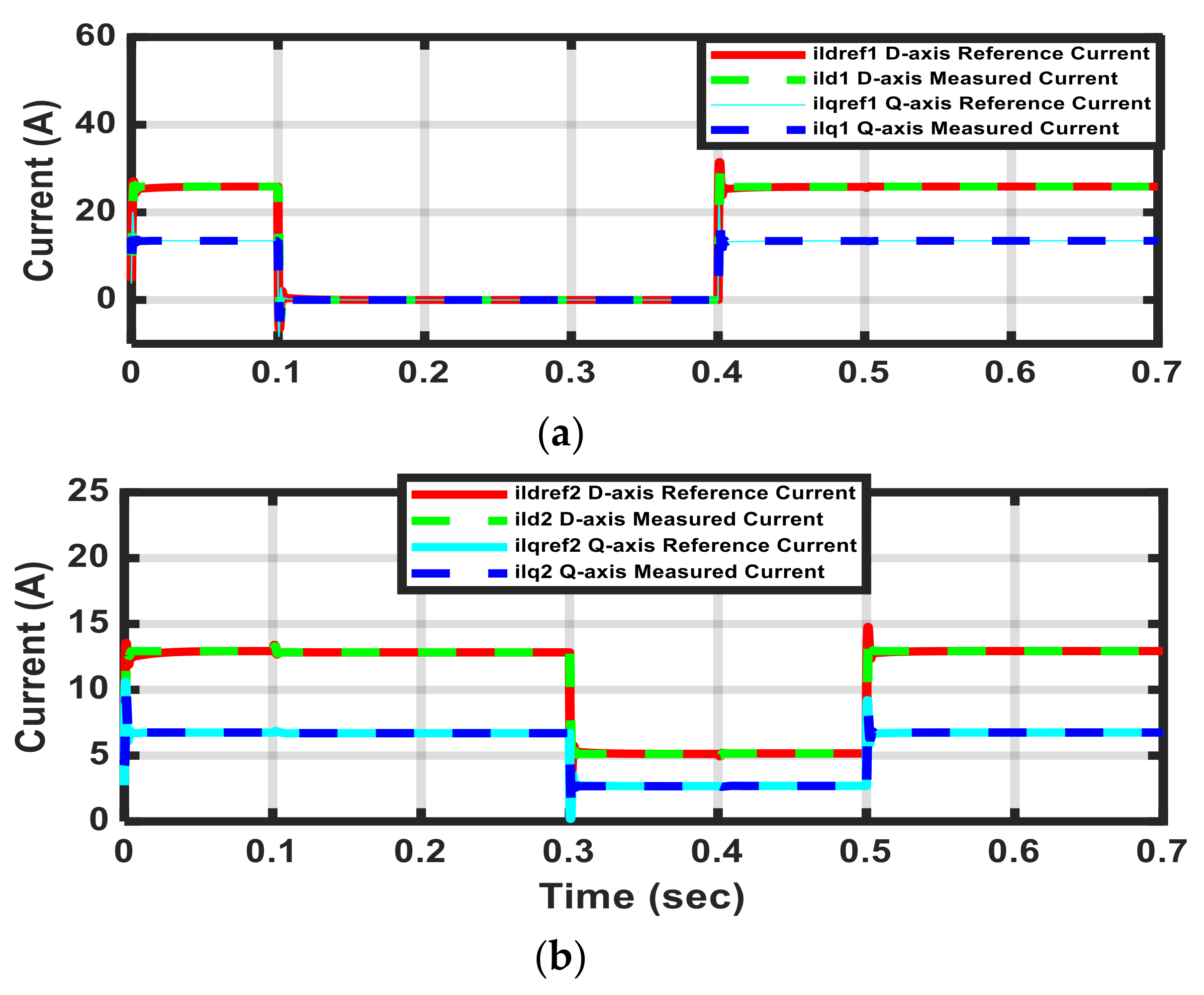
The proposed controller has been tested when a 5 kVA inverter-based DG connected to the grid. Firstly, the reference real power has been stepped down from 5 kW to 3 kW at t = 0.1 sec. Figure 8 shows the calculated and reference real and reactive powers for this disturbance. Both injected real and reactive powers are mostly following the reference powers. While Figure 9 depicts the calculated and reference real and reactive powers when the injected reactive power has been stepped down from 5 kVAR to 3 kVAR without any change in the injected real power. Both injected real and reactive powers are almost tracking the reference powers. It could be observed from the results that the controller has quick responses and track the references effectively. Additionally, the results show a reasonable steady state response at the beginning and even after clearing disturbance. (show as Table 1 and Table 2).
Secondly, Figure 10 shows the microgrid dynamic response with step changes in real and reactive powers. Both active and reactive powers have been simultaneously stepped down from 5 kW to 3 kW and from 5 kVAR to 3 kVAR respectively at t = 0.1 sec. The results show how the proposed controller is working perfectly making the calculated powers track the reference powers perfectly.
Thirdly for further testing of the controller robustness, a three-phase fault disturbance has been applied at the PCC at t = 0.1 sec. Fault has been cleared at t = 0.4 sec. Figure 11 shows the dynamic responses of the three-phase output currents and their dq components where the system has been recovered from the fault. The proposed controller shows a very good transient performance. The calculated real and reactive powers are following the reference real and reactive powers in a good way under this fault disturbance.
Finally, to confirm the superiority of the proposed controller, a comparison between the proposed controller and the existing control scheme (power calculator presented in [21]) has been carried out. As it was mentioned before, the reference currents were calculated using the reference powers and measured output voltage in [21] while in the proposed method, an optimal power PI controller has been implemented to obtain the reference currents where the calculated powers were compared with the reference powers. Figure 12 and Figure 13 show the dynamic response of the dq components of the inverter currents, and real and reactive powers when the injected real power stepped down from 5 kW to 3 kW at t = 0.1 sec. It can be shown from the results that the proposed controller shows better performance in terms of tracking the reference powers and steady state response. Figure 14 and Figure 15 illustrate the dynamic response of the real and reactive powers for stepping up the injected reactive power from 3 kVAR to 5 kVAR and stepping down the injected real power from 5 kW to 3 kW at t = 0.1 sec. The results illustrate how the calculated powers follow perfectly the reference powers without any delay in the proposed controller while in the existing control scheme [21], there is a small delay when the calculated powers try to track the reference powers. Figure 16 and Figure 17 depict the dynamic response of the dq components of the inverter currents, real and reactive powers for simultaneous step changes in both real and reactive powers from 3 kW to 5 kW and from 3 kVAR to 5 kVAR respectively at t = 0.1 sec. The system response due to a three-phase fault applied at the PCC is depicted in Figure 18. The results illustrate the superiority of the proposed controller. The response of the microgrid equipped with the proposed controller keep better and fast reference tracking in a good way.

5.2. Two DGs Cases

In the second case, two different rated (5 KVA and 10 KVA) inverter-based DG units are controlled to bring their real and reactive powers with the grid as shown in Figure 2. Both units are tied together to share the injected powers to the grid. The proposed controller has been examined for different disturbances. Figure 19 shows the dynamic response of the calculated and reference real powers with different step changes for the two different DGs at different times. Firstly, the injected real powers of DG1 and DG2 have been stepped up from 7.5 kW to 10 kW at t = 0.1 sec and from 2.5 kW to 5 kW at t = 0.3 sec respectively. Figure 20 illustrates the dynamic response of the dq components of the inverter output currents related to this disturbance. Both injected real and reactive powers are mostly following the reference powers. It could be observed from the results that the controller has quick responses and track the references effectively. Secondly, Figure 21 depicts the dynamic response of the real and reactive powers with simultaneous step change in the injected real powers of DG1 and DG2. For DG1, the real power has been stepped down from 10 kW to 6 kW at t=0.1 sec then it has been stepped up from 6 kW to 10 kW at t = 0.4 sec. While for DG2, the real power has been stepped down from 5 kW to 2 kW at t = 0.3 sec then it has been stepped up from2 kW to 5 kW at t = 0.5 sec. With the proposed controllers, it is obvious that the response overshoot is not significant. The response of the microgrid equipped with the proposed controller keep better and fast reference tracking in a good way.
A severe disturbance has been applied to check the controller capability for such disturbance. At t = 0.1 sec, the microgrid lost DG1 and restore it again at t = 0.4 sec. Meanwhile, the real power of DG2 has been stepped down from 5 kW to 3 kW between t = 0.3 sec and t = 0.5 sec. Figure 22 shows the real and reactive power responses of DG1 and DG2 at this disturbance. While, Figure 23 shows the responses of the dq components of the inductor current of DG1 and DG2 at this disturbance. It can be concluded from this disturbance that the proposed controller keeps the microgrid operation in a better shape. Additionally, the proposed controller has a fast response tracking the reference and in a good way.

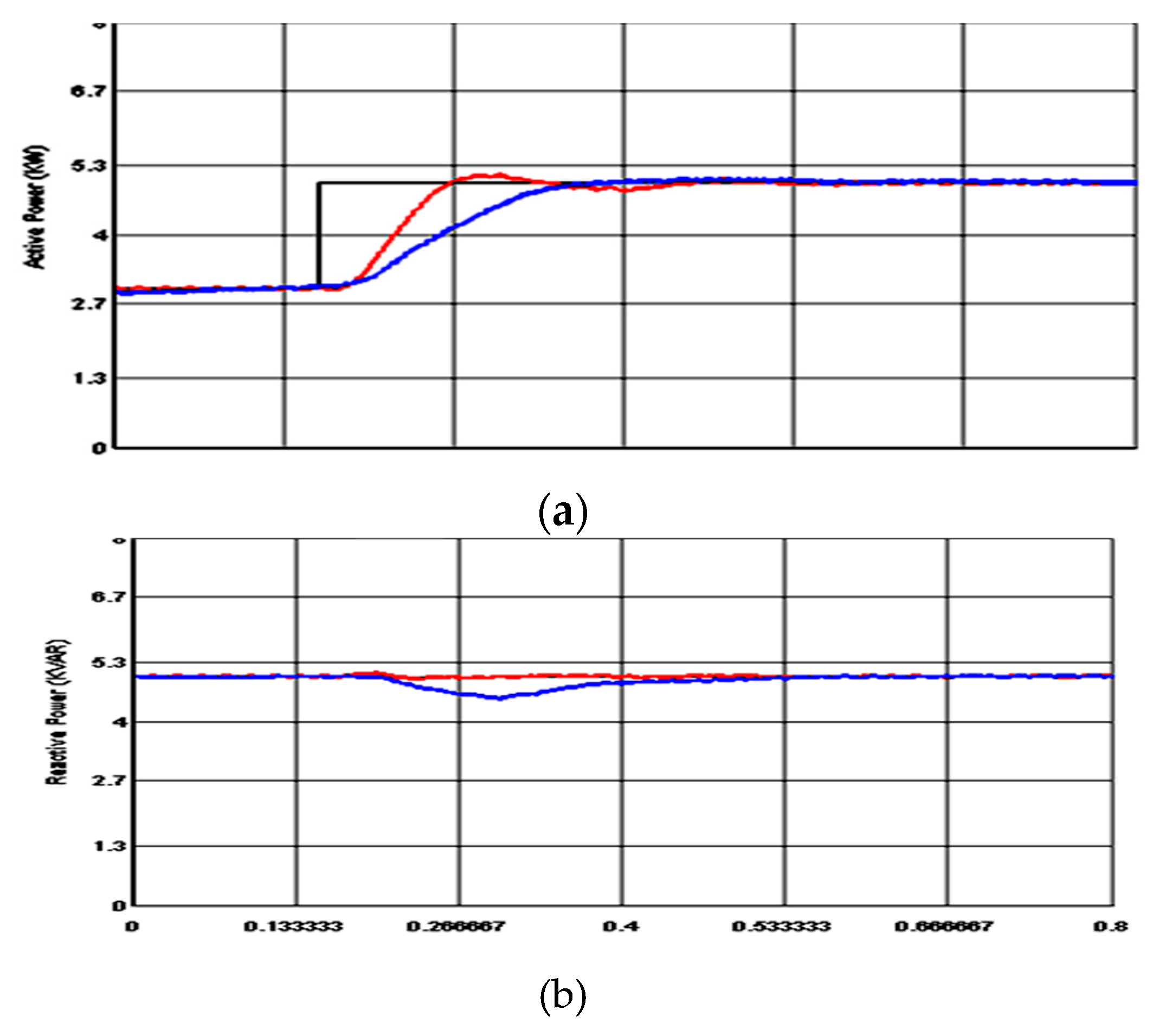
6. Real-Time Implementation

The considered inverter-based DG with its proposed controller has been implemented on real-time digital simulator (RTDS) as shown in Figure 24 [34,35,36]. For verifying the theoretical simulation, the proposed microgrid is implemented and simulated in RTDS. RTDS works in real-time to provide solutions to power system equations quickly enough to accurately represent conditions in the real world [26]. RTDS offers superior accuracy over analogue systems. It allows for comprehensive product and/or configuration tests. RTDS provides a variety of transient study possibilities. With detailed models of power system components, a model resembles closely the real system setup in the RTDS. As RTDS works in continuous sustained real-time, the simulation is performed fast. With standard library blocks, using their physical representation, components such as grid, LC filter, inverter bridge and coupling inductor are modeled. The RTDS model of the grid-connected microgrid includes the models of the inverter, LC filter, the coupling impedance and the grid is given in Figure 24. The firing pulse generator and triangle wave generator blocks used for generating the firing pulses of the inverter gates are also included in Figure 24.
Additionally, the RTDS models of the power and current controllers are illustrated in Figure 25. The optimal controller parameters are engaged with the implemented RTDS model. Firstly, with stepping up the injected real and reactive powers from 3 kW to 5 kW and from 3 kVAR to 5 kVAR respectively, the dynamic response of the dq currents components, real and reactive powers are shown in Figure 26, Figure 27, Figure 28 and Figure 29. Secondly, Figure 30 and Figure 31 show the dynamic response of the real and reactive powers when a single-phase fault occurs at PCC. Finally, real and reactive powers have been stepped for the proposed system and for the work done previously in [21]. A comparison between the new and old controllers has been presented to prove the superiority of the proposed one. Figure 32 and Figure 33 depict the dynamic response of the real and reactive powers for the previous and proposed controllers. As shown in the RTDS results, during the step changes, the controller has a reasonable capability to track the reference signal without significant overshoots. The proposed controller effectiveness under these disturbances is confirmed in RTDS. The given results illustrate the superiority of the proposed controller. The response of the microgrid equipped with the proposed controller keep better reference tracking in a good way. The results show the controller effectiveness under different disturbances.

7. Conclusion

In this paper, an optimal PQ control technique for inverter-based DG in the grid-connected microgrid has been presented. A power controller has been optimally designed to control a predefined injected real and reactive powers to the utility. Moreover, the current controller parameters and filter components have been optimized. To improve the microgrid dynamic response, the optimized controller parameters have been adjusted. For microgrid stability enhancement, with the proposed objective function, PSO has been employed for searching the optimal settings of the optimized controller and filter parameters. Two different cases in terms of the microgrid configuration have been considered to inject and share a predefined set real and reactive powers respectively. In both cases, the microgrid performance has been investigated for severe disturbances to clarify how the proposed optimal control improved the microgrid dynamic stability. The proposed controller response has been compared with that given in the literature. The time domain simulations confirm the proposed approach usefulness over the previous controller. For the proposed microgrid, the obtained RTDS results verify the usefulness of the proposed controllers for different disturbances. Additionally, RTDS results demonstrate reasonable performance with effective damping characteristics of the proposed controller.

Author Contributions

M.A.H. and M.A.A. initiated the idea, formulated the problem, performed the simulation, and analyzed the results. M.Y.W. participated in paper revision stage, contributed in enhancing the simulation results, and shared in paper writing.

Funding

This research was funded by King Fahd University of Petroleum and Minerals through the Power Research Group funded project RG171002 and King Abdullah City for Atomic and Renewable Energy (K.A. CARE).

Conflicts of Interest

The authors declare no conflict of interest.

References

  1. Colmenar-Santos, A.; Reino-Rio, C.; Borge-Diez, D.; Collado-Fernández, E. Distributed generation: A review of factors that can contribute most to achieve a scenario of DG units embedded in the new distribution networks. Renew. Sustain. Energy Rev. 2016, 59, 1130–1148. [Google Scholar] [CrossRef]
  2. Tavakoli, M.; Shokridehaki, F.; Akorede, M.F.; Marzband, M.; Vechiu, I.; Pouresmaeil, E. CVaR-based energy management scheme for optimal resilience and operational cost in commercial building microgrids. Electr. Power Energy Syst. 2018, 100, 1–9. [Google Scholar] [CrossRef]
  3. Hassan, M.; Abido, M. Optimal design of microgrids in autonomous and grid-connected modes using particle swarm optimization. IEEE Trans. Power Electron. 2011, 26, 755–769. [Google Scholar] [CrossRef]
  4. Mohammadi, F. Power Management Strategy in Multi-Terminal VSC-HVDC System. In Proceedings of the 4th National Conference on Applied Research in Electrical, Mechanical Computer and IT Engineering, Tehran, Iran, 4 October 2018. [Google Scholar]
  5. Mohammadi, F.; Nazri, G.A.; Saif, M. A Bidirectional Power Charging Control Strategy for Plug-in Hybrid Electric Vehicles. Sustainability 2019, 11, 4317. [Google Scholar] [CrossRef]
  6. Hassan, M.A.; Worku, M.Y.; Abido, M.A. Optimal design and real time implementation of autonomous microgrid including active load. Energies 2018, 11, 1109. [Google Scholar] [CrossRef]
  7. Danish, M.S.S.; Matayoshi, H.; Howlader, H.O.R.; Chakraborty, S.; Mandal, P.; Senjyu, T. Microgrid Planning and Design: Resilience to Sustainability. In Proceedings of the 2019 IEEE PES GTD Grand International Conference and Exposition Asia (GTD Asia), Bangkok, Thailand, 19–23 March 2019; pp. 253–258. [Google Scholar]
  8. Danish, M.S.S.; Senjyu, T.; Funabashi, T.; Ahmadi, M.; Ibrahimi, A.M.; Ohta, R.; Howlader, H.O.R.; Zaheb, H.; Sabory, N.R.; Sediqi, M.M. A sustainable microgrid: A sustainability and management-oriented approach. In Proceedings of the Applied Energy Symposium and Forum, Renewable Energy Integration with Mini/Microgrids; Energy Procedia: Rhodes, Greece, 2018; Volume 159, pp. 160–167. [Google Scholar]
  9. Sahoo, S.K.; Sinha, A.K.; Kishore, N.K. Control techniques in AC, DC, and hybrid AC–DC microgrid: A Review. IEEE J. Emerg. Sel. Top. Power Electron. 2018, 6, 738–759. [Google Scholar] [CrossRef]
  10. Xin, H.; Zhang, L.; Wang, Z.; Gan, D.; Wong, K.P. Control of island AC microgrids Using a fully distributed approach. IEEE Trans. Smart Grid 2015, 6, 943–945. [Google Scholar] [CrossRef]
  11. Bai, W.; Lee, K. Distributed Generation System Control Strategies in Microgrid Operation. Preprints of the 19th World Congress. The International Federation of Automatic Control, Cape Town, South Africa, 24–29 August 2014; pp. 11938–11943. [Google Scholar]
  12. Serban, I.; Marinescu, C. Control strategy of three-phase battery energy storage systems for frequency support in microgrids and with uninterrupted supply of local loads. IEEE Trans. Power Electron. 2014, 29, 5010–5020. [Google Scholar] [CrossRef]
  13. Jena, S.; Babu, C.; Mishra, G.; Naik, A. Reactive power compensation in inverter-interfaced distributed generation. In Proceedings of the 2011 International Conference on Energy, Automation, and Signal (ICEAS), Bhubaneswar, India, 28–30 December 2011; pp. 1–6. [Google Scholar]
  14. Hornik, T.; Zhong, Q. A Current-control strategy for voltage-source inverters in microgrids based on H∞ and repetitive control. IEEE Trans. Power Electron. 2011, 26, 943–952. [Google Scholar] [CrossRef]
  15. Zhang, N.; Tang, H.; Yao, C. A systematic method for designing a PR controller and active damping of the LCL filter for single-phase grid-connected PV inverters. Energies 2014, 7, 3934–3954. [Google Scholar] [CrossRef]
  16. Jeong, H.; Kim, G.; Lee, K. Second-order harmonic reduction technique for photovoltaic power conditioning systems using a proportional-resonant controller. Energies 2013, 6, 79–96. [Google Scholar] [CrossRef]
  17. Yao, Z.; Xiao, L.; Guerrero, J. Improved control strategy for the three-phase grid-connected inverter. IET Renew. Power Gener. 2015, 9, 587–592. [Google Scholar] [CrossRef]
  18. Kumar, V.; Jees, S.; Gomathi, V. Control techniques for single phase inverter to interface renewable energy sources with the microgrid. Int. J. Adv. Res. Electr. Electron. Instrum. Eng. 2014, 3, 437–447. [Google Scholar]
  19. Lia, S.; Jaithwaa, I.; Suftaha, R.; Fua, X. Direct-current vector control of three-phase grid-connected converter with L, LC, and LCL filters. Electr. Power Compon. Syst. 2015, 43, 1644–1655. [Google Scholar] [CrossRef]
  20. Schonardie, M.; Coelho, R.; Schweitzer, R.; Martins, D. Control of the active and reactive power using dq0 transformation in a three-phase grid-connected PV system. In Proceedings of the 2012 IEEE International Symposium Industrial Electronic, Hangzhou, China, 28–31 May 2012; pp. 264–269. [Google Scholar]
  21. Hassan, M.; Abido, M. RTDS implementation of the optimal design of the grid-connected microgrids using particle swarm optimization. In Proceedings of the International Conference on Renewable Energies and Power Quality (ICREPQ’12), Santiago de Compostela, Spain, 28–30 March 2012. [Google Scholar]
  22. Dai, M.; Marwali, M.N.; Keyhani, A. Power flow control of a single distributed generation unit. IEEE Trans. Power Electron. 2008, 23, 343–352. [Google Scholar] [CrossRef]
  23. Jang, M.; Mihai, C.; Agelidis, V.G. A single-phase grid-connected fuel cell system based on a boost-inverter. IEEE Trans. Power Electron. 2013, 28, 279–288. [Google Scholar] [CrossRef]
  24. Fazeli, S.M.; Ping, H.W.; Rahim, N.B.A.; Ooi, B.T. Individual-phase decoupled PQ control of three-phase voltage source converter. IET Gener. Transm. Distrib. 2013, 7, 219–1228. [Google Scholar] [CrossRef]
  25. Adhikari, S.; Li, F.X.; Li, H.J. PQ and PV control of photovoltaic generators in distribution systems. IEEE Trans. Smart 2015, 6, 2929–2941. [Google Scholar] [CrossRef]
  26. Chen, M.; Wang, H.; Zeng, G.; Dai, Y.; Bi, D. Optimal P-Q control of grid-connected inverters in a microgrid based on adaptive population extremal optimization. Energies 2018, 11, 2107. [Google Scholar] [CrossRef]
  27. Hassan, M.; Abido, M. Real time implementation and optimal design of autonomous microgrids. Electr. Power Syst. Res. 2014, 109, 118–127. [Google Scholar] [CrossRef]
  28. Patel, R.; Li, C.; Meegahapola, L.; McGrath, B.; Yu, X. Enhancing optimal automatic generation control in a multi-area power system with diverse energy resources. IEEE Trans. Power Syst. 2019, 34, 3465–3475. [Google Scholar] [CrossRef]
  29. Hassan, M.; Abido, M. Optimal power sharing of an inverter–based autonomous microgrid. In Proceedings of the Conference on Renewable Energies and Power Quality (ICREPQ’13), Bilbao, Spain, 20–22 March 2013. [Google Scholar]
  30. Al-Saedi, W.; Lachowicz, S.W.; Habibi, D.; Bass, O. Voltage and frequency regulation-based DG unit in an autonomous microgrid operation using particle swarm optimization. Int. J. Electr. Power Energy Syst. 2013, 53, 742–751. [Google Scholar] [CrossRef]
  31. Dong, D.; Wen, B.; Boroyevich, D.; Mattavelli, P.; Xue, Y. Analysis of phase-locked loop low-frequency stability in three-phase grid-connected power converters considering impedance interactions. IEEE Trans. Ind. Electron. 2015, 62, 310–321. [Google Scholar] [CrossRef]
  32. Errami, Y.; Ouassaid, M.; Maaroufi, M. Modelling and optimal power control for permanent magnet synchronous generator wind turbine system connected to utility grid with fault conditions. World J. Model. Simul. 2015, 11, 123–135. [Google Scholar]
  33. Kennedy, J.; Eberhart, R. Particle swarm optimization. In Proceedings of the IEEE International Conference on Neural Networks, Perth, Australia, 27 November–1 December 1995; pp. 1942–1948. [Google Scholar]
  34. Worku, M.; Hassan, M.; Abido, M. Real time energy management and control of renewable energy based microgrid in grid connected and island modes. Energies 2019, 12, 276. [Google Scholar] [CrossRef]
  35. RTDS Technologies. Real Time Digital Simulator Power System and Control User Manual; RTDS Technologies: Winnipeg, MB, Canada, 2009. [Google Scholar]
  36. Mahmoud, M.; Sattar, A. Real time implementation of the grid to analyze the performance of the variable speed wind turbine−generator during grid disturbances. Int. J. Comput. Electr. Eng. 2016, 8, 104–116. [Google Scholar] [CrossRef]
Figure 1. Grid-connected microgrid (One distributed generation’s (DGs) case).
Sustainability 11 05828 g001
Figure 2. Grid-connected microgrid (Two DGs case).
Sustainability 11 05828 g002
Figure 3. Proposed microgrid controller.
Sustainability 11 05828 g003
Figure 4. Phase locked loop (PLL) model.
Sustainability 11 05828 g004
Figure 5. Proposed power controller.
Sustainability 11 05828 g005
Figure 6. Current controller.
Sustainability 11 05828 g006
Figure 7. Proposed particle swarm optimization (PSO) computational flow chart.
Sustainability 11 05828 g007
Figure 8. (a) Active power response at real power step down change. (b) Reactive power response at real power step down change.
Sustainability 11 05828 g008
Figure 9. (a) Active power response at real power step down change. (b) Reactive power response at real power step down change.
Sustainability 11 05828 g009
Figure 10. (a) Active power response at real and reactive powers step down changes. (b) Reactive power response at real and reactive powers step down changes.
Sustainability 11 05828 g010
Figure 11. (a) D-axis current response at three-phase fault disturbance at PCC. (b) Q-axis current response at three-phase fault disturbance at PCC. (c) Three-phase current response at three-phase fault disturbance at PCC.
Sustainability 11 05828 g011
Figure 12. (a) Active power response at step down change in real power. (b) Reactive power response at step down change in real power.
Sustainability 11 05828 g012aSustainability 11 05828 g012b
Figure 13. (a) D-axis current responses at step down change in real power. (b) Q-axis current responses at step down change in real power.
Sustainability 11 05828 g013
Figure 14. (a) Active power response at step up change in reactive power. (b) Reactive power response at step up change in reactive power.
Sustainability 11 05828 g014aSustainability 11 05828 g014b
Figure 15. (a) Active power response at step down change in reactive power. (b) Reactive power response at step down change in reactive power.
Sustainability 11 05828 g015
Figure 16. (a) Active power response with simultaneous step up change in real and reactive powers. (b) Reactive power response with simultaneous step up change in real and reactive powers.
Sustainability 11 05828 g016aSustainability 11 05828 g016b
Figure 17. (a) D-axis current responses with simultaneous step change. (b) Q-axis current responses with simultaneous step change.
Sustainability 11 05828 g017
Figure 18. (a) D-axis current responses for two controllers at the fault disturbance. (b) Q-axis current responses for two controllers at the fault disturbance.
Sustainability 11 05828 g018aSustainability 11 05828 g018b
Figure 19. (a) Active power responses at stepped up active power disturbances at different times. (b) Reactive power responses at stepped up active power disturbances at different times.
Sustainability 11 05828 g019aSustainability 11 05828 g019b
Figure 20. (a) D-axis current responses at stepped up active power disturbance. (b) Q-axis current responses at stepped up active power disturbance.
Sustainability 11 05828 g020
Figure 21. Power responses with stepped up and down real powers at different times.
Sustainability 11 05828 g021
Figure 22. (a) Active power responses when the microgrid lost DG1 for 0.3 sec. (b) Reactive power responses when the microgrid lost DG1 for 0.3 sec.
Sustainability 11 05828 g022
Figure 23. (a) D-axis current responses when the microgrid lost DG1 for 0.3 sec (b) Q-axis current responses when the microgrid lost DG1 for 0.3 sec.
Sustainability 11 05828 g023
Figure 24. Laboratory setup for real-time digital simulation.
Sustainability 11 05828 g024
Figure 25. (a) Power controller on real-time digital simulation. (b) Current controller on real-time digital simulation.
Sustainability 11 05828 g025aSustainability 11 05828 g025b
Figure 26. (a) Active power responses at stepped up real power disturbance. (b) Reactive power responses at stepped up real power disturbance.
Sustainability 11 05828 g026
Figure 27. (a) D-axis inductor current response at stepped up real power disturbance. (b) Q-axis inductor current response at stepped up real power disturbance.
Sustainability 11 05828 g027
Figure 28. (a) Active power responses at stepped up reactive power disturbance. (b) Reactive power responses at stepped up reactive power disturbance.
Sustainability 11 05828 g028
Figure 29. (a) D-axis inductor current response at stepped up reactive power disturbance. (b) Q-axis inductor current response at stepped up reactive power disturbance.
Sustainability 11 05828 g029
Figure 30. (a) Active power responses at fault disturbance at PCC. (b) Reactive power responses at fault disturbance at PCC.
Sustainability 11 05828 g030
Figure 31. (a) D-axis inductor current response at fault disturbance at PCC. (b) Q-axis inductor current response at fault disturbance at PCC.
Sustainability 11 05828 g031
Figure 32. (a) Active power responses at stepped up active power disturbance. (b) Reactive power responses at stepped up active power disturbance.
Sustainability 11 05828 g032
Figure 33. (a) Active power responses at stepped up reactive power disturbance. (b) Reactive power responses at stepped up reactive power disturbance.
Sustainability 11 05828 g033aSustainability 11 05828 g033b
Table 1. Optimal parameters for one DG case.
PI Power Controller Parameters
kpp(Amp/ Watt)kip(Amp/ Joule)kpq(Amp/ Watt)kiq(Amp/ Joule)
0.0007375.031380.0007375.03138
PI Current Controller Parameters
kid(Volt/Current. Sec)kpq(Volt/ Amp)kiq(Volt/Current. Sec)kpd(Volt/ Amp)
649.548.87277649.548.87277
Filter Parameters
Cf (μF)Lf (mH)Rd (Ω)
10.42.17610.6539
Table 2. Optimal parameters for two DGs case.
PI Power Controller Parameters
kpp(Amp/ Watt)kip(Amp/ Joule)kpq(Amp/ Watt)kiq(Amp/ Joule)
DG10.00095.00.00095.0
DG20.00085425.970560. 00085425.97056
PI Current Controller Parameters
kid (Volt/Current. Sec)kpq(Volt/ Amp)kiq(Volt/Current. Sec)kpd(Volt/ Amp)
DG1606.37510606.37510
DG2632.2855.1117632.2855.1117
Filter Parameters
Cf(μF)Lf(mH)Rd(Ω)
11.0510.0

