1. Introduction
In the construction market, special attention has been given in the last decade to environmentally friendly, sustainable and anti-seismic constructions.
“The construction industry accounts for about 20% of the global emissions. However, with crumbling buildings and an expanding population, there is a need for more buildings. By constructing environmentally friendly buildings and focusing on the longevity of the building, it is better for the environment” [
1]. As mentioned by The Building and Construction Authority of Singapore, [
2], “the economical light gauge steel frame system is increasingly being used in America, Europe, Australia and New Zealand”. Steel framing is a special system based on skeleton constructions made of galvanized steel wall profiles, delivered individually or mounted in walls, floors, ceilings, roofs, etc. The system is designed according to the principle “do it yourself”—dry construction [
3].
In [
4] there is presented a description of the design and main execution phases with main regard to the structural aspects, for the British Force School (BFS) of NATO in Naples. The exclusive use of cold-formed steel (CFS) profiles in a dry solution provides characteristics of high structural efficiency, uniform quality of the components, simplicity and rapidity of assembly and, not least, recyclability of the base materials.
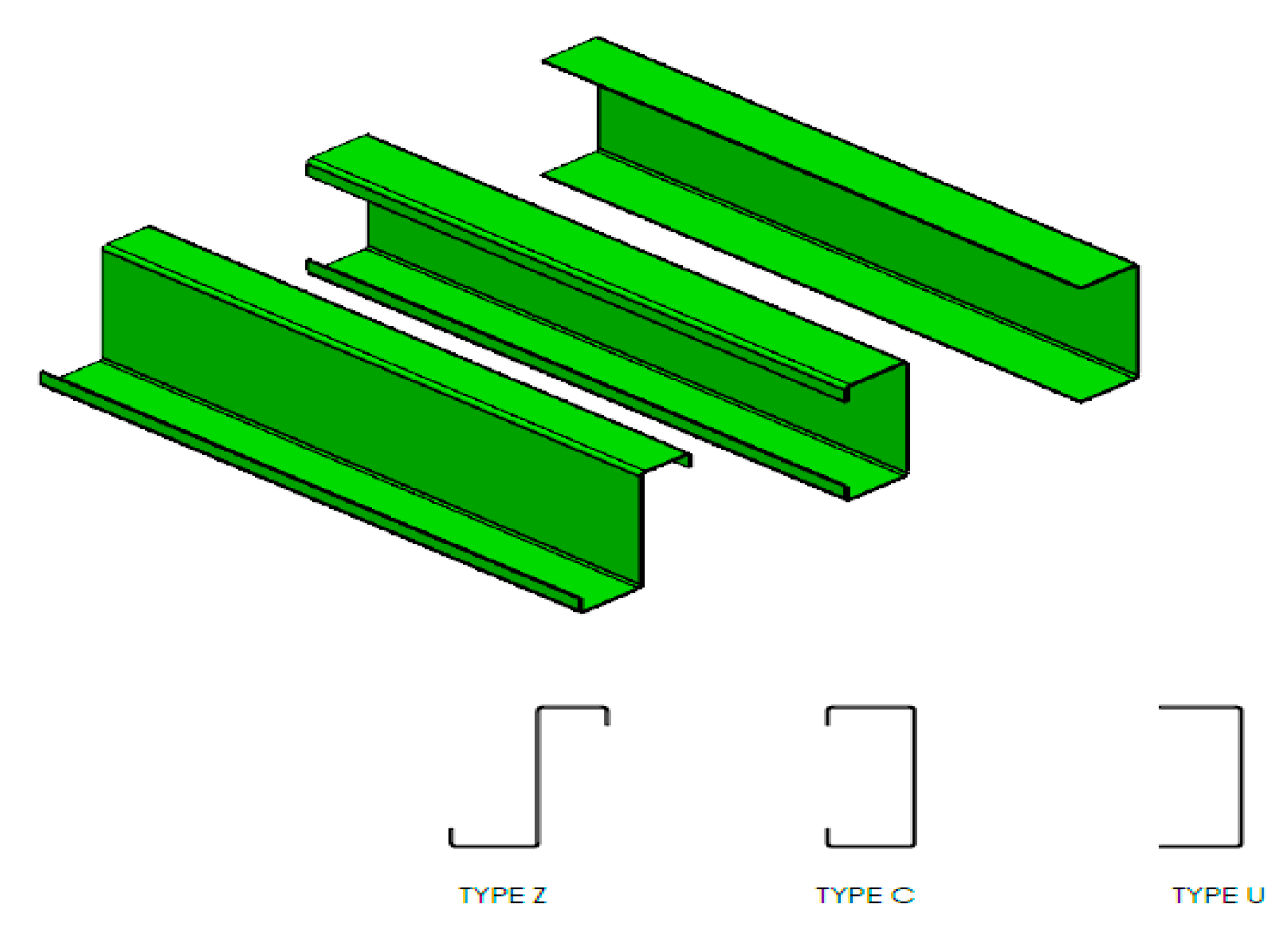
Following this trend, in Romania, there is an increased interest in ecological metallic buildings—such as houses, offices and storage halls made of light gauge steel (LGS) profiles. Commonly used LGS profile types (Z, C, U) are presented in
Figure 1. Other types of LGS/LFS (lightweight steel-framed) profiles, as well as studies on strategies for improving the thermal resistance of LSF elements are presented in detail in [
5].
The execution stages of steel framed construction are shown in
Figure 2.
A study on the application of lightweight steel framed (LSF) construction systems in hot climate is shown in [
7]. The main goal is to determine which geometric variables correlate with the energy performance and to provide some guidelines to foster efficient LSF buildings in hot climates (villas in Kuwait). Two relevant conclusions of this study are that: Roof types do not show significant correlation with energy consumption, while exterior wall types present moderate to strong negative correlation for energy consumption with window-to-floor ratio, window-to-wall ratio and window-to-exterior surface ratio; building shape has a very weak to weak negative correlation with energy consumption, thus showing that designers are free to explore various building forms without compromising the energy consumption of the building.
There are many advantages of steel framed constructions from the sustainability point of view. Steel is 100% recyclable and actually 80% of the steel used in construction comes from recycling. Steel is light so there is a need for less foundation and the construction can be done on regular even poor soils [
8].
An important benefit of the lightweight steel framed construction is its high safety in cases of earthquake. There are many studies [
9,
10] on the seismic behavior of lightweight structures, models and simulation of structural components deformations with, or without, considering joints, connection elements and non-structural components. One relevant conclusion is that even if the most advanced and very detailed numerical models can adequately predict test results, work still remains to bring the findings of research to design practice guidelines.
The LGS profile is obtained by the cold plastic deformation process from galvanized steel strips of low thickness (the most used values for thickness are of 0.75–3.0 mm). The material is, basically, low carbon steel, with high ductility and good plasticity. As mentioned in [
8] the yield strength of this steel varies in the range of 220 up to and 500 N/mm
2, most of the steels used having yield strength from 320 up to 350 N/mm
2.
In Romania, LGS profiles are obtained by cold roll forming, from galvanized steel strips, which are zinc coated of 115 g/m
2. The steel is similar to S235 (SR EN 10025-2:4, European standard) which is equivalent to: 1015 (USA), RSt37-2 (Germany, DIN), AE235B-FN (Spain, UNE) or E235B (international ISO) [
11]. When tested at 180° bending (according to SR ISO 7438) no cracks either in the coating, or steel, appeared on the strips.
Worldwide there are many studies on green building projects, such as integrating the life cycle assessment into the building design decision making [
12] or identifying the critical success and failure factors so that building practitioners should strategize and efficiently manage their projects [
13]. The first life cycle analysis of a cold formed steel house, which is based on the real case “ELISSA House” is presented in [
14]. The structural system based on cold formed steel components can provide environmental impacts that are half of a conventional system, while at the same time saving on material quantities. Many of the non-structural components have the potential to be reintroduced in the life cycle, and thus the lightweight steel systems will be really capable of providing a fundamental contribution towards a circular economy future.
These above-mentioned issues are known and also carefully dealt with by Romanian companies that build ecological steel framed constructions. One of its representatives (a general manager) has pointed out the estimated benefits of improving the mechanical characteristics of the LGS profile’s material. It was the requirement of higher values for hardness and tensile strength, on customized profile zones/parts (such as upper/lower part, near the joints), where loading and, consequently, stresses and strains are proved to be high and the profiles broke.
The purpose of this paper is to present the research results in improving the mechanical characteristics of light gauge steel, in certain zones conventionally named “of interest” for the profile. Thus, the specific objectives are as follows: Identification of surface hardening process type; choice of adequate material; optimization of induction process; validation of results.
2. Materials and Induction Process Experiments
The material used for the LGS profile is steel with low carbon content that ensures high plasticity and therefore good roll forming (cold roll deformation). Usually, the material’s thickness is up to 1.2 mm (zinc coated). In fact, it is limited by the technical characteristics of the cold rolling (roll forming) equipment, as the higher the thickness, the higher the values required for roll forming forces.
Initially, the research was focused on 300 mm and 420 mm length LGS profiles, of 1.2 mm thickness, zinc plated and with a C type transversal section—see
Figure 3.
These are the profiles in trusses, estimated to be submitted to intensive loading, due to rain, snow and/or earthquake. Simulation of stress and strain states has evidenced the zones where the material hardness and tensile strength should be improved. The steel is S235 (SR EN 10025-2:4) with 0.17 % carbon content.
In order to improve the material’s mechanical characteristics, especially in the superficial layer, thermochemical treatments solutions have been considered and studied, as mentioned below.
Carburizing—increasing the carbon percentage in the superficial layer of the part by heating at a higher temperature of 870–950 °C, by maintaining this temperature for a specific time and then by cooling (tempering). This solution is not appropriate for the light gauge steel profiles because of their low thickness and the requirement of a special enceinte for the treatment.
Nitriding—improving a material’s hardness by heating the parts at 350–600 °C in environments able to release atomic nitrogen, maintaining for a relatively long period and then slowly cooling down. Here, no successive thermal treatment is required. Really, this solution was not adequate because the LGS profiles did not need complete surface hardening (nitriding). The long duration for this process and the costs are not justifiable, as the profiles are not submitted to severe wear and contact pressure, or do not need special high fatigue strength. This thermochemical treatment requires a special enceinte.
The main issue of improving the mechanical characteristics for the LGS profiles is focused only on specific zones—with high loadings and often failures. These specific zones have been identified by modeling and simulation results (see
Figure 3) and, not in the least by the experience of builders of steel framed constructions in Romania. Based on all mentioned above, induction hardening by high frequency current has been considered as the method of improving the surface characteristics only in the zones of interest of an LGS profile. Due to the small material’s thickness (of light gauge steel), the hardening through the entire thickness that would cause the material high fragility and, therefore, make the LGS profile unusable in the construction of buildings must be avoided.
Induction heating is based on the phenomenon of magnetic induction and the film effect, according to which an electric current is induced in peripheral layers of the workpiece introduced into a magnetic field. In a very short time, in these superficial layers the temperature level required by the hardening heat treatment conditions is reached (in between 100 °C and 3000 °C), while in the core of the material there are no structural transformations and therefore no modification of the initial properties. Surface heating provides a distribution of internal stresses per section which leads to increased fatigue resistance for the hardened and minimal deformation (because the core remains rigid). Due to the short time required for heating the surface, the process is very productive and fit for mass production [
15]. Usually, in induction hardening by a high frequency current, the layer thickness exceeds 1.0 mm. For decreasing the penetration depth, the electric current frequency has to be over 500 kHz [
15,
16]. Moreover, the common induction hardened parts are shafts, gear teeth and bolts with dimensions large enough to ensure a surface layer depth of 2.0–4.0 mm or even more.
For the studied material and part, the LGS profile, there were at least two challenges: Low carbon content (for the hardening) and low thickness (for the depth penetration). This is why the first experiments were not encouraging at all as the profile had been burned in the zones where the induction process was taking place—see
Figure 4.
It can be noticed that despite the low thickness and burn of material, the thermal deformation of the profile base was not relevant, that in fact being a good point.
Because of these poor (bad) results, one more trial was that of considering an increased thickness of the material, such as 3.0 mm. This value is mentioned in the technical characteristics of the roll forming equipment, PINNACLE XS6 (used in the Romanian SME production hall), and is fit when manufacturing LGS profiles used in steel framed constructions with more than two floors (up to maximum 10 floors). There were performed induction hardening experiments (see
Figure 5) on rectangular samples of the S235 material. The induction process specific parameters are as follows: Electric power, P (kW), and induction coil’s speed, v (mm/s). Due to the equipment limitation, the frequency of the electric current could not be adequately varied and controlled. So, this is the reason why the process variable inputs studied are only P and v.
In the specialty literature there are not many data regarding the induction hardening process parameter values fit for a certain material type and least of all for the S235 steel (European standard). That is why, based on industry experience [
17], several parameters’ values within the range of 40–80 kW for the electric power, P and of 5–8 mm/s for the induction coil’s speed, v, were tested. The experiment’s results evidenced that the lower values for P and the higher values for v resulted in no visible change of the material’s surface, while the higher values for P and the lower values for v resulted in a burned surface. The experiments were done on rectangular samples with dimensions of 200 × 300 (mm × mm). These values were chosen so that the sample should be adequately fixed on the induction machine clamping system and, further on, standardized samples should be obtained from it. These samples are required to determine the tensile strength of the hardened material and their shape, lengths and width are standardized (for tensile strength tests, see EN ISO 6892).
The good point was that material’s burning was avoided, and the process could be correctly performed on rectangular material samples. Still, at a glance, one could notice the poor surface change. The metallographic analyses on the samples evidenced the poor transformation of the pearlite into bainite/martensite—see
Figure 6 (the metallographic structure of the sample before and after the induction process was on).
Further measurements on the surface hardness evidenced that the hardness values for the surface were almost the same as those of the material before the induction hardening.
Based on the above results that were not quite good, it has been decided to consider changing the material for the LGS profiles. Still, major changes could not have been done as one important characteristic of the material that has to be kept is its good plasticity. That is due to the process of obtaining the profiles which is the cold roll forming (plastic deformation). From another point of view, in order to have good results for the hardening process on customized zones of the LGS profile, the carbon content should be higher than in the S235 material. In the specialty literature it is recommended that a carbon percentage higher than 0.3–0.4% be used for good results in hardening; still for percentages over 0.2–0.25% hardness increasing is achievable [
15]. It is known that the higher the carbon percentage, the lower the plasticity.
This kind of “optimization” problem (plasticity vs. hardness) was assumed to be solved by choosing the S355 J2+AR material, for the LGS profile. This steel is mentioned in the SR EN 10025-2:4 (European standard), and is equivalent to: A572 (USA), E36-2 (France, AFNOR), AE355B (Spain, UNE) or 50B (England, BS) [
18]. The carbon content is 0.24 % and the material thickness is 3.0 mm.
Considering the results of the previous experiments (see above) and the basic design of the experiment rules [
19] the induction hardening process input variables were as follows,
- -
electric power, P (kW): 50 (−1); 60 (50%) (0); 70 (60%) (+1);
- -
longitudinal speed of coil, v (mm/s): 5 (−1); 6 (0); 7 (+1);
where it can be noticed that each of the input values has three variation levels coded by: −1 (minimum); 0 (medium); +1 (maximum). These mentioned values are estimated as fit based on the authors’ previous knowledge and the professional background (experience) of the people working in the thermal treatments industry (Romanian company) [
17,
20].
It can be noticed that the sample’s surface looked exactly as a hardened one—see
Figure 7 (the induction process and raw material samples). Furthermore, there is no large curvature of the sample because of the thermal heating even if its upper side edge was “free” (not clamped) while the induction process was on.
The specimens for the metallographic analysis (and the standard specimens for determining the tensile strength) were obtained by plasma flame CNC cutting—see
Figure 8 (plasma flame process and specimens).
The metallographic analysis was done after standard preparation of the samples by metallurgical microscope system, OLYMPUS GX51—see
Figure 9 (the metallographic structures before and after induction, respectively, on the same side as and the opposite side to the induction coil).
For the raw material, the structure is in rows, characteristic of the laminated and normalized material, mostly ferrite. For the induction hardened material, the transformation of the pearlite into martensite (especially, the bainitic/martensitic transformation) that obviously has the effect of increasing the superficial layer hardness can be noticed.
Further analysis evidences that, on the sample side opposite to the induction coil, the pearlite content is higher than the one on the side facing the induction coil, this proving that the hardening process did not occur through all the material’s thickness. A clear delimitation of the hardened layer throughout the material’s thickness cannot be made, but an average estimation is that the hardened layer does not exceed 20–30% (of the 3 mm thickness) considering as reference the side near the induction coil. In fact, hardening only the superficial layer is the result wanted to be achieved.
3. Results and Discussion
Improving the material’s mechanical characteristics in the hard-loaded zones of the LGS profile is the target for applying the induction hardening process. Measurements on superficial layer hardness have been made in order to determine the interdependence relation of the induction process variables. The Vickers values on the metallographic samples under 1 kgf (kilogram force) loading, conventionally named HV1, were determined. On each sample’s surface there were performed three measurements at different surface points. The values considered for further discussion represent the mean of the three measurements.
This 1 kgf (kilogram force) was considered adequate, due to the material’s characteristics and thickness. The lower loading does not ensure the penetration depth into the whole hardened layer, while the higher loading generates the deterioration of the hardened layer by penetration into all the material’s thickness. The images and results obtained are presented in
Figure 10 (the measuring process and penetration print).
The complete study of induction hardening by high frequency current applied to the LGS material aims to determine the relation of the process variables that are as follows:
- -
Inputs: The electric power, P [kW] and longitudinal speed of coil, v [mm/s]
- -
Output: The hardness, HV1
This was done by applying the statistics method design of experiments and regression analysis. The experimental program is a central composite design (CCD) and the regression analysis was done by means of the DOE KISS software (free/student version), [
19,
21,
22].
For the regression analysis there is the need to have coded values for the input variables. As has been stated above (
Section 2: “Materials and Induction Process Experiments”) each of them has three variation levels, which are: Minimum, medium and maximum. Conventionally, they are coded by −1, 0 and +1, respectively.
The relations of the coded and natural values are given by Equation (1).
The design of experiments and the results for the HV1 superficial layer hardness are shown in
Table 1.
The model of the superficial layer hardness determined by regression analysis is:
Some further results of the regression analysis, meaning graphical plots are presented in
Figure 11 (the Pareto graph and surface plot).
The Pareto chart of coefficients evidences how strong the influence of each input variable and their interactions are on the output variable. The 3D surface is the one that points out the variation of the surface hardness HV1 on the induction process parameters, P and v.
These research results were validated. Considering the regression model Equation (2) and based on the expertise of the construction engineers (from the Romanian company [
6], the induction hardening process was applied to specific zones of the LGS profiles of trusses, the S355 material. The profiles are 450 mm long and the zones are situated mainly on the upper part (near the joints)—see
Figure 3.
High fragility of material must be avoided, and this is why the elongation before fracture, A
0, is the main issue. The values for A
0 have to be below 8–10%. These values have been determined on the standard tensile strength specimen [
23] obtained at the same time as the metallographic sample (see
Figure 8).
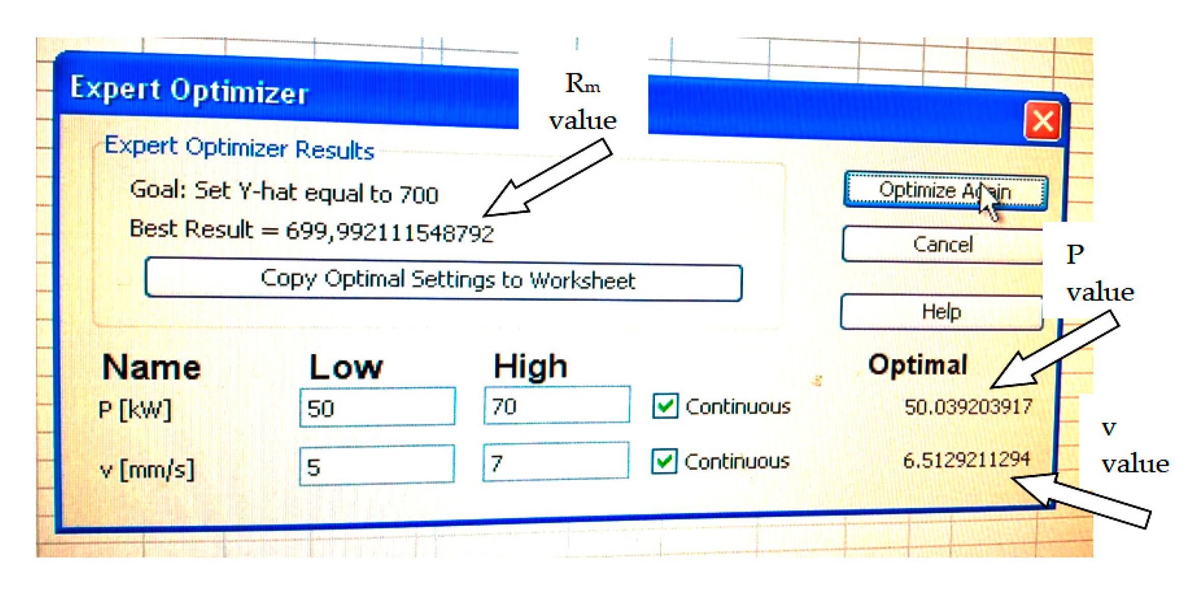
For example, a value of 8% for the elongation results when the tensile strength (
Rm) is about 700 N/mm
2—higher than the simulated values (von Mises stress) shown in
Figure 3. This value for R
m is obtained for the S355 LGS profile’s material when the induction process parameters are:
P = 50.039 ≅ 50 kW;
v = 6.5129 mm/s ≅ 6.5 mm/s (the calculated values are approximated so as to be able to set them on the induction equipment control panel).
The above-mentioned values for
P and
v were determined by the tensile strength regression model—Equation (3) determined in [
23] and, further, by the DOE KISS software Expert optimizer module—see
Figure 12.
where
Rm is the tensile strength (N/mm
2).
For these values (
P = 50 kW and
v = 6.5 mm/s) by Equation (2) the resulting value for the superficial layer hardness can be determined, that is: HV1 = 298.44. The hardness value for the “raw” material is 199 (see
Table 1). An increase of almost 50 % under the condition of not exceeding the elongation before fracture (A0) by more than 8% (that is the reason for good ductility) can be noticed.
For the induction hardening of the LGS material there were choices of selecting the induction coil’s type—see
Figure 13.
The first type was an induction coil surrounding the entire LGS profile and shaped according to its transversal section. After some preliminary tests the major disadvantage because of the profile zones where the induction heat (from both outside and inside the profile) got through the entire material thickness and even burned it was noticed. Moreover, too high fragility was induced and even on the outer surface at corners some cracks appeared.
The second type of induction coil was a circular one, surrounding the outer profile transversal section. Cracks on the outer side, at the corners, resulted while testing induction hardening with this type of coil. The explanation stands in the fact that while roll forming of the LGS profiles, bending at the corners generates residual tensile stresses in the outer surface (and compression in the inner surface). While heating and further fast cooling down by blasts of water (the phases specific to induction hardening by high frequency current), these residual stresses get higher and finally cause cracks of the surface.
The third (accepted) choice was that of the interior induction coil shaped according to the C type profile’s interior section. Any excessive overheating of the material is avoided, as well as its fragility caused by the excessive hardening, due to the fact that heat comes only from one side of the material’s thickness (see also
Figure 9).
Models of the mentioned studied induction coils are presented in
Figure 13 (surrounding and interior of the LGS profile’s transversal section).
The heat in the induction hardening process of the LGS material is generated by the high frequency current in the induction coil. One important aspect for good process results is that of cooling the heated zone—with blasts of water. The water jet pressure, the distance of the cooling piece from the induction coil, the shape of the cooling jet when referred to the shape of the profile are important. In the experiments all these aspects were studied, and an adequate solution was chosen. This was mainly based on the experience of the personnel from the company where the induction process was carried out and, not in the least, on the availability (limitations) of the induction equipment used. Therefore, for the inner induction coil (see
Figure 13d) the cooling piece was of rectangular shape type so that the cooling water jet also functioned from inside the profile’s section (after heating by the induction coil). No further treatments had to be done after getting the profile out of the equipment clamping system.
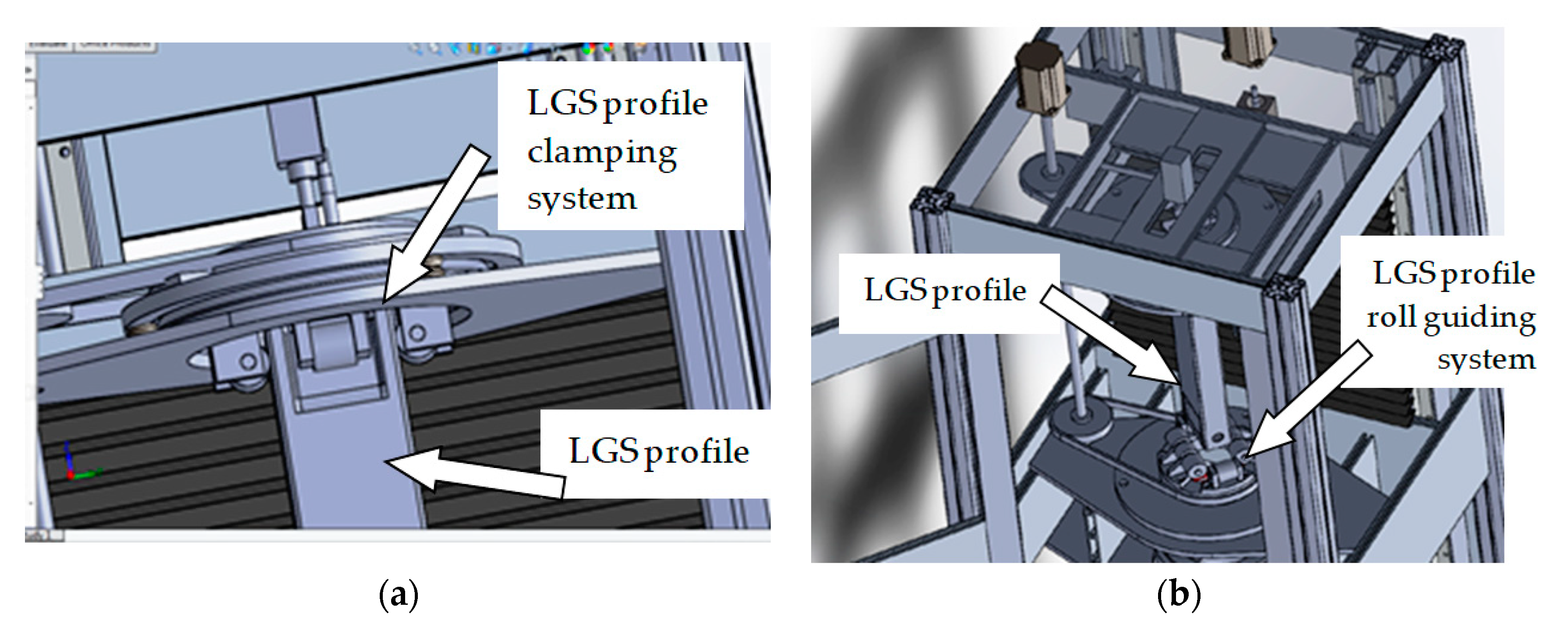
Another aspect considered was that of minimizing the thermal deformation resulting after the induction process. That is why a system for clamping the profile and continuously guiding it through all the induction process time was designed—see
Figure 14. This system is part of a piece of equipment that could be used with a mobile high frequency current generator (see also [
20]) directly in the production hall of the LGS profile manufacturer [
6].
Images taken while assembling the LGS profiles into the panels for light framed sustainable eco-constructions are presented in
Figure 15. These panels have as components the LGS profiles obtained by roll forming and induction hardening.
Based on real production data obtained from the Romanian company that builds metallic constructions [
6], the material consumption for a 6 m height and 200 square meters deposit construction made of C type LGS profiles is about 105 kg of zinc coated steel (S355 type) per square meter of construction. By applying the induction hardening process to customized zones of the LGS profiles, for the same metallic construction, the material consumption decreased up to 81 kg per square meter. The manufacturer’s conclusion was that due to the increased material hardness (but within reasonable limits for good elongation and therefore ductility) a reduction by 17% of the material’s consumption was obtained.
4. Conclusions
The aim of this study was to improve the mechanical characteristics of light gauge steel in “interesting” zones of the LGS profile. This is a requirement identified on the Romanian construction market for reducing raw material consumption.
Improving a material’s hardness and tensile strength stands as a challenge caused by the following limitations: Reduced material thickness; low carbon content of material (required for the cold deformation process); estimated profile thermal deformation; customized profile section to harden.
The typical material of the LGS profiles (S235) was replaced by another one (S355) with a slightly higher carbon percentage but still with good plasticity required by the cold roll forming process. The induction hardening process does influence the material hardness, generating an increase of more than 25% (compared to the value of the raw material), even 50%—for the example presented in
Section 3: “Results and Discussion”.
The metallographic analysis evidenced phase transformations specific to the induction hardening process, meaning the transformation of the ferritic (pearlite) structure into a bainitic/martensitic one. This transformation is highly accentuated in the material on the sample side near the induction coil.
The parameters specific to the induction hardening process, namely, the power of the electric current, P, and the longitudinal speed of the coil, v, have significant influence on the material hardness, HV1. Increasing the power values, P, results in increased hardness values while an increase in the velocity values, v, causes decreased hardness values, HV1.
The validation of the results proved an average reduction by 17% of the material’s consumption (S355 type steel) for a certain building (6 m height and 200 square meters).
The research presented by this article is of real interest for the manufacturer of LGS profiles and, even more, for the builders of light framed constructions. In fact, these research results are the “answer” to the requirement clearly stated by the representatives of a Romanian company that builds ecological steel framed constructions. Changing material type (S235, S355 and others similar) with high strength steel alloy is not possible due to the major conditions for light gauge steel profiles: Low thickness, plate shape as raw material and good plasticity required for the roll forming process (basic process for obtaining the LGS profiles). Further development of this research would involve a study on improving other materials’ characteristics (such as compression, torsion resistance, corrosion resistance) of benefit for the LGS profiles in steel framed constructions.


