Article

An Improved Power Management Strategy for MAS-Based Distributed Control of DC Microgrid under Communication Network Problems

Department of Electrical and Information Engineering, Seoul National University of Science and Technology, 232 Gongneung-ro, Nowon-gu, Seoul 01811, Korea
*
Author to whom correspondence should be addressed.
Sustainability 2020, 12(1), 122; https://doi.org/10.3390/su12010122
Submission received: 29 November 2019 / Revised: 17 December 2019 / Accepted: 20 December 2019 / Published: 22 December 2019
(This article belongs to the Special Issue Integration of AC/DC Microgrids into Power Grids)

Abstract

:
In this paper, an improved power management strategy (PMS) for multi-agent system (MAS)-based distributed control of DC microgrid (DCMG) under communication network problems is presented in order to enhance the reliability of DCMG and to ensure the system power balance under various conditions. To implement MAS-based distributed control, a communication network is constructed to exchange information among agents. Based on the information obtained from communication and local measurements, the decision for the local controller and communication is optimally given to guarantee the system power balance under various conditions. The operating modes of the agents can be determined locally without introducing any central controller. Simultaneously, the agents can operate in a deliberative and cooperative manner to ensure global optimization by means of the communication network. Furthermore, to prevent the system power imbalance caused by the delay in grid fault detection and communication in case of the grid fault, a DC-link voltage (DCV) restoration algorithm is proposed in this study. In addition, to avoid the conflict in the DCV control among power agents in case of the grid recovery under communication failure, a grid recovery identification algorithm is also proposed to improve the reliability of DCMG operation. In this scheme, a special current pattern is generated on the DC-link at the instant of the grid recovery by the grid agent, and other power agents identify the grid recovery by detecting this current pattern. Comprehensive simulations and experiments based on DCMG testbed have been carried out to prove the effectiveness of the PMS and the proposed control schemes under various conditions.

1. Introduction

In recent years, the concept of microgrids (MGs) has been introduced as an effective and potential solution to integrate various renewable energy sources (RESs) such as wind and solar into the grid [1]. For the purpose of stabilizing the system operation under the intermittent nature of RESs and continuous variations of load demand, energy storage systems (ESSs) are usually used in MGs [2]. With the development of technology, electric vehicles can be utilized as multiple ESSs to stabilize the system operation of MGs by precise control strategy and simultaneously to regulate the voltage and frequency of the power grid [3]. Under the normal grid conditions, MG operates in the grid-connected mode in which the system power balance is ensured by the grid. In the case of grid fault, however, the MG is completely independent of the grid, operating in the islanded mode. In this sense, the system power balance of MG should be achieved by means of a coordinated operation of power units such as RESs, ESSs, and grid according to load demands [4]. As the reliability issue becomes a primary interest, there has been an approach to develop a fast proactive hybrid DC circuit breaker which interrupts the DC fault [5]. As another approach to enhance the reliability, the DC-link voltage (DCV) control method has been presented for MG by the conventional centralized power flow control strategy [6].
Depending on the types of bus voltage, MGs can be mainly classified into DC microgrids (DCMGs), AC microgrids (ACMGs), and hybrid AC/DC microgrids [7]. Among them, DCMGs are known to be more attractive due to several advantages as compared with the other configurations. DCMGs provide a convenient interface in connecting various DC loads and operate with better efficiency in transmission and distribution. Moreover, the consideration for the harmonic injection and frequency stability is not necessary. As a result, DCMGs can be considered as an efficient, reliable, and cost-effective option in some applications [8].
In view of the communication perspective, the control of DCMGs can be divided into three methods: centralized control, decentralized control, and distributed control [9]. In centralized control, the data from distributed power units are collected in a central controller (CC). Then, the CC processes the acquired data to send the feedback commands back to units via digital communication links (DCLs). The centralized control normally suffers from many drawbacks related to the single point of failure, reliability, flexibility, and scalability [10]. On the other hand, the decentralized approach can provide high reliability and flexibility due to the absence of CC and DCLs among distributed power units in the system [11]. Nevertheless, it is quite difficult to ensure the global optimization of the entire system because each distributed unit lacks the information of others. By analyzing two above control methods, the distributed control is introduced as an optimal solution which combines the advantages as well as restricts the disadvantages of both methods [12]. In particular, the single point of failure as in the centralized control can be avoided since CC does not exist in the system. In addition, as compared to the decentralized approach, the problem of global optimization is effectively solved by implementing the DCLs among neighboring units. Therefore, a distributed control is considered as a potential alternative for the control of the power system in the future.
For the distributed control, a multi-agent system (MAS) is employed as an advanced technique which is able to handle complex problems in DCMGs including the system power balance, reliability, and stability in a more flexible and intelligent way [13]. Therefore, several studies relied on the MAS-based distributed control strategy of DCMG have been presented recently in the literature [14,15,16,17,18]. In [14], an intelligent control based on the MAS technique is presented to control the MG in both the grid-connected and islanded modes. In this scheme, the optimization in real-time control of the MG is achieved by the negotiation among agents to share the available energy. In [15], a novel distributed optimal control which applies the consensus algorithm-based MAS is introduced in order to realize the optimal control as well as to provide fast frequency recovery under various load conditions. With the aim of developing secondary control by MAS-based distributed control for the frequency recovery in islanded MG, a distributed robust control strategy is presented in [16]. To obtain the accurate reactive power-sharing among agents, a MAS-based hierarchical distributed coordinated control strategy is proposed in [17]. In [18], both reactive power-sharing and voltage control are taken into account by implementing a distributed MAS-based finite-time consensus algorithm in two layers. Although the aforementioned schemes can achieve key functions of control for MG such as the system stability, energy management, active and reactive power controls, the implementation of system control only focuses on purely inverter-based distribution generations (DGs). However, in practice, most present MG applications involve the networks of mixed agents such as inverter-based DGs, RESs, ESSs, and loads. Because these MG components have different characteristics, each type of agent should be designed considering a specific control strategy during operation. Furthermore, the problems of communication network in the implementation of MAS-based distributed control have not been considered yet.
In the MAS-based distributed control, the communication network problems such as delay or failure are ubiquitous during the process of information transmission among agents, which may cause the system malfunction, instability, or even collapse [19]. In order to analyze the effect of communication network problems on the system stability, the control scheme has been tested under the presence of time delay in [20,21]. However, since the effect of time delay on system performance has been only validated by the simulation tests in these studies, the reliability of system operation is not completely ensured in reality. Moreover, as shown in the simulation results of these studies, larger time delay results in longer and stronger fluctuation of the controlled variables such as the voltage and frequency in case of load variation. For the purpose of improving the control performance further, the time delay is considered in the designs of the secondary controllers [22,23]. In [24,25], a local controller based on the delay-dependent H method is presented to deal with the transmission time delays. Although the schemes in [22,23,24,25] can guarantee the system stabilization, the control performance is still limited due to the requirement of an allowable maximum upper bound for the time delay. Motivated by this concern, a communication-based control strategy that can maintain the system stability with unbounded time delays is presented in [26]. In comparison to time delay, the communication failure is known to be more serious in the communication-based systems. To address the drawback of the data loss caused by communication failure, a prediction scheme is constructed in [27], in which each agent forecasts the lost data by using an extreme learning machine.
As mentioned earlier, the problems of the communication network result in the performance deterioration or even system instability, which is more serious in cases of grid fault and grid recovery. When DCMG operates in the grid-connected mode, the system power balance is normally achieved by implementing the DC-link voltage control mode (DCVM) by the grid agent. When the grid fault occurs, the grid agent informs the other agents of the fault state via the communication links, and then, the DCMG operation is switched into the islanded mode. After receiving the grid fault information, the remaining agents automatically undertake the system power balance by implementing their own DCVM. Unfortunately, however, unexpected communication problems prevent the remaining agents from recognizing the grid fault information instantly. As a result, any agents cannot serve to achieve the system power balance. On the contrary, as soon as the grid is recovered from the fault, the grid agent should inform the recovery state to the other agents, and then switch the operation mode into DCVM. In compliance with this mode change, the remaining agents should stop their DCVM operation, turning over the authority of DCV to the grid agent. However, the remaining agents may fail to recognize the grid recovery in the presence of communication problems, which causes the conflict in the system control because two voltage control sources exist in DCMG.
To deal with the aforementioned drawbacks caused by the communication network problems in both the grid fault and grid recovery cases, an improved power management strategy (PMS) using MAS-based distributed control of DCMG is presented in this paper. In this study, DCMG consists of a grid agent, a battery agent, a wind power generation system (WPGS) agent, and a load agent. To ensure the system power balance under various conditions, each agent investigates the information obtained from both the local measurement and the neighboring agents via the communication lines. Then, the decision for local control mode and communication data is optimally made for the system power balance. By using this control scheme, the control mode of agents can be determined locally without any intervention of CC, which effectively avoids the single point of failure as in the centralized control. Also, all the agents can operate in a deliberative and cooperative manner to ensure globally optimal operation by means of the communication network. In addition, to deal with the impact of communication problems in the case of the grid fault, a DCV restoration algorithm is introduced to restore the DCV stably to its nominal value. Furthermore, to recognize the grid recovery reliably in other agents even under the communication failure, the grid recovery identification algorithm is introduced. For this purpose, a special current pattern is generated on DC-link by the grid agent once the grid is recovered. By detecting this current pattern on DC-link, the remaining agents can reliably identify the grid recovery even without the communication. To validate the feasibility of the MAS-based distributed control as well as the proposed schemes under the communication problems, the simulations based on the PSIM software and the experiments based on laboratory prototype DCMG testbed are carried out.
This paper is organized as follows: Section 2 describes the system configuration of DCMG with MAS-based distributed control. Power management and control strategies of local agents are discussed in detail in Section 3. Section 4 presents the proposed control strategies under communication network problems. The simulation and experimental results are given in Section 5 and Section 6, respectively. Finally, Section 7 concludes the paper.

2. System Configuration of DCMG with MAS-based Distributed Control

2.1. MAS-based Distributed Control of DCMG

Figure 1 shows the configuration of DCMG with the MAS-based distributed control approach, in which system units are represented by corresponding autonomous agents, namely, grid agent, battery agent, WPGS agent, and load agent. The functions of each agent are summarized as follows.
Grid agent: the grid agent receives the information on the grid statuses such as the normal, fault, or recovery from the grid operator (GO) to determine the operation mode of DCMG in the grid-connected or islanded. In the grid-connected mode, the grid agent ensures the supply–demand power balance in DCMG by controlling the exchange power between DCMG and grid within the maximum exchange power. In addition, the grid agent is responsible for the seamless transfer between the grid-connected and islanded modes.
Battery agent: the battery agent receives the information on the state of DCV control from the grid agent via a communication line. If the grid agent is incapable of controlling the DCV, the battery agent is switched into the DCVM to regulate the DCV at the nominal value. Furthermore, by collecting the state of charge (SOC), battery voltage, and battery current, the battery agent realizes relevant control modes to ensure that the battery is operated in a safe range.
WPGS agent: generally, the WPGS agent is operated in order to extract the maximum power from the wind into DC-link by the maximum power point tracking (MPPT) mode. However, when both the grid and battery agents are incapable of regulating the DCV, the WPGS agent changes the operation from the MPPT mode to DCVM to regulate the DCV.
Load agent: the load agent is responsible for monitoring the load demand, and also, providing the information on load demand to other agents. Another role of this agent is to implement the load shedding (SHED) and load reconnection (RECO) to keep the system stable as well as to optimize the available power on DC-link.
As can be seen in Figure 1, each agent can not only monitor and control the corresponding power units but also communicate with other agents through the communication network. By using the communication among agents, the system control is realized in a distributed way in which each agent makes its control decision locally. This enhances the control performance and system reliability as compared with the centralized and decentralized control approaches.

2.2. System Communication Topology

In general, the communication network plays an important role in MAS-based distributed control. Figure 2 presents the system communication topology used in this study, in which each agent communicates with others via communication lines. Defining an appropriate communication network that specifies the data information exchanged among agents is the crucial step in the design procedure of MAS-based distributed control [28]. In this paper, the exchange data, data type, and data information are described in Table 1 in detail. For example, the maximum supplied power, the maximum injected power, and the grid states are transmitted through the communication line 1 into the grid agent in the format of double and binary data.

3. Power Management and Control Strategy of Local Agents

3.1. Control Strategy of Grid Agent

Figure 3 shows the control strategy which is designed in this study for local operation of the grid agent in MAS-based distributed control approach. As can be seen, the entire algorithm is divided into three layers, namely, the information collection, the decision of control mode, and the decision of communication. In the information collection layer, the information is gathered from the local measurement as well as GO and neighbor agents. The GO provides the information on the maximum exchange powers and grid states to the grid agent through the communication line 1 as in Table 1. Local measurement and neighbor agents offer the information on the voltage, current, and supply–demand power relationship. After gathering the necessary information, the grid agent determines appropriate control modes as shown in the decision of control mode layer. If the grid has a fault, the grid agent switches the operation to IDLE mode, and the variable G c t r l is set to 0, which indicates that the grid agent is incapable of controlling the DCV. This information is transmitted to other agents.
When the grid fault does not occur, the grid agent further investigates whether the grid is being normal or the grid is recovered. If the grid is being normal, the grid agent determines the operation as DCVM-REC or DCVM-INV to regulate the DCV and to guarantee the system power balance depending on the supply–demand power relationship. While the operation DCVM-REC compensates the power deficit by injecting the power from the grid to DCMG, the operation DCVM-INV makes the grid absorb the power surplus on DC-link. When the required power to maintain the system power balance becomes larger than the maximum level obtained from GO, the grid agent switches the operation into constant power control mode (CPCM). Since the exchange power between the grid and DCMG is at the maximum possible level under the CPCM, the grid agent is not able to control the DCV.
In case that the grid is recovered from the fault, a grid recovery control algorithm is triggered. The details of this algorithm and function for the flags F G 1 , F G 2 , and F G 3 will be explained in Section 4. After the decision of local control mode is released, the information on the ability of the DCV control by the grid agent is transmitted to other agents via communication lines.
Based on the control strategy of the grid agent in Figure 3, the local control block is implemented to realize all the operating modes [6].

3.2. Control Strategy of Battery Agent

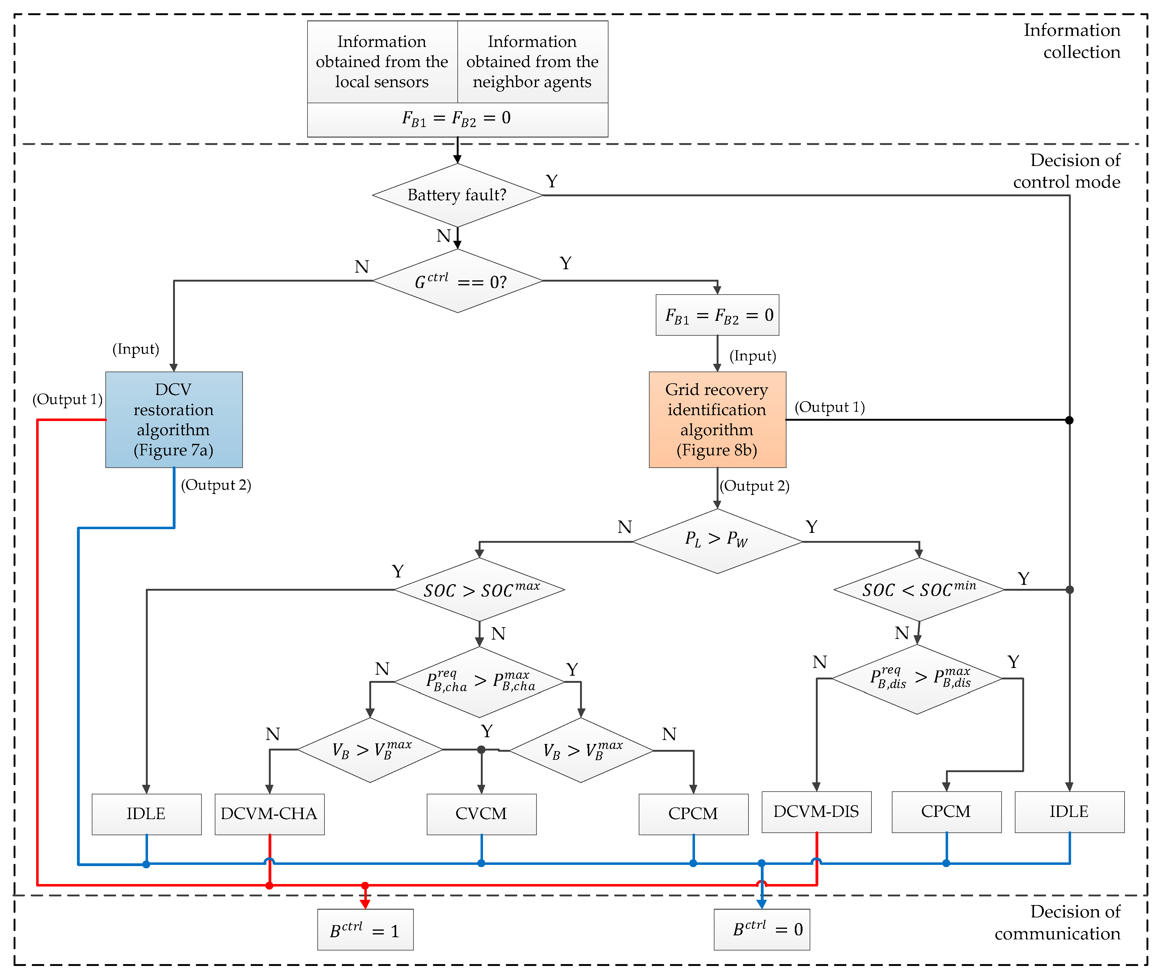
Figure 4 shows the control strategy which is designed in this study for local operation of the battery agent in MAS-based distributed control approach. Similarly, the entire algorithm is divided into three layers. In the information collection layer, the information is collected from the local measurement and neighbor agents. By using the local measurement, the information of battery state, SOC, voltage, and current can be obtained locally. The information on the supply–demand power relationship and the ability of the DCV control by the grid agent is obtained via communication lines from neighbor agents. In this figure, the DCV restoration, the grid recovery identification algorithm, and the function of flags F B 1 and F B 2 will be explained in Section 4.1 and Section 4.2.
If the battery has a fault, the battery agent switches the operation into IDLE mode and the variable B c t r l is set to 0 to imply that the battery agent is incapable of controlling the DCV. This information is also transmitted to other agents.
In case the battery is normal, the battery agent determines appropriate control modes according to the supply–demand power relationship, battery SOC, voltage, and current to ensure the system power balance in DCMG under various conditions. When the battery statuses such as SOC, voltage, and required power are within their predefined ranges, the battery agent determines the operation as DCVM-DIS to inject the power to DC-link or DCVM-CHA to absorb the power from DC-link for the purpose of regulating the DCV to its nominal value. If the battery SOC goes beyond the safe range defined by S O C m i n and S O C m a x , the battery agent switches the operation into IDLE mode to avoid overcharging or overdischarging. In addition, if the required charging power of P B , c h a r e q and the required discharging power of P B , d i s r e q exceed the maximum levels of P B , c h a m a x and P B , d i s m a x , the operation CPCM is realized to charge/discharge the battery with its maximum capability. As a result, the overheat or damage during the battery operation can be avoided. Similarly, in order to prevent the battery from overcharging voltage, the constant voltage control mode (CVCM) is realized to charge the battery with the maximum voltage level. After the decision of local control mode is given, the information on the ability of the DCV control by the battery agent ( B c t r l ) is simultaneously informed to other agents via communication lines.
Based on the control strategy of the battery agent in Figure 4, the local control block is implemented to realize all the operating modes [6].

3.3. Control Strategy of WPGS Agent

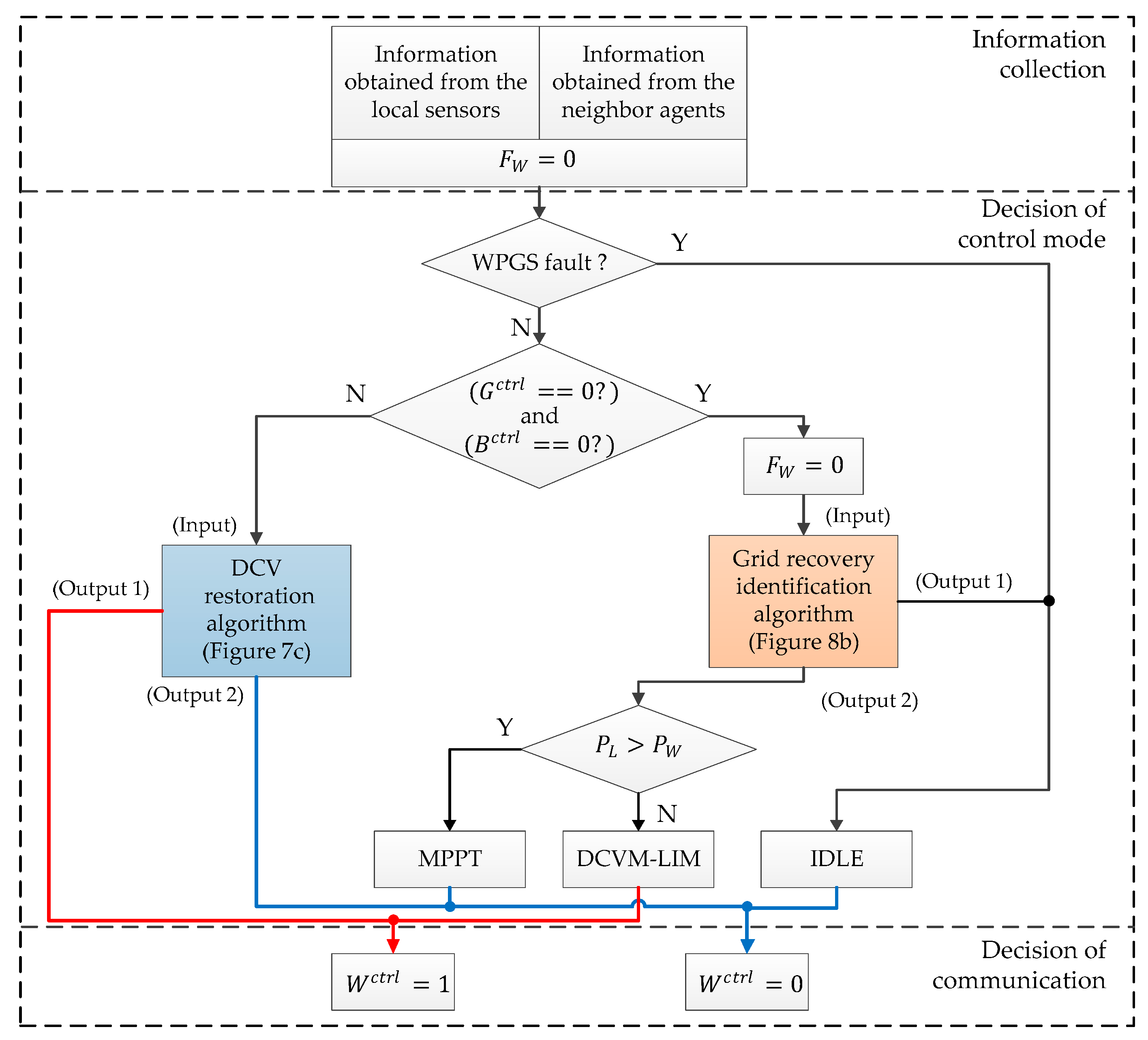
Figure 5 shows the control strategy for local operation of the WPGS agent in MAS-based distributed control approach. Similar to the above agents, the entire algorithm is also divided into three layers. In the information collection layer, the information is obtained from the local measurement and neighbor agents. By using the local measurement, the extracted power from wind turbine ( P W ) can be obtained. The information on the supply–demand power relationship and the ability of the DCV control of battery and grid agent is gathered from neighbor agents. In this figure, the DCV restoration, the grid recovery identification algorithm, and the function of flag F W will be presented in Section 4.1 and Section 4.2.
If the WPGS has a fault, the WPGS agent switches the operation into IDLE mode, and the variable W c t r l is set to 0 to indicate that the WPGS agent is incapable of controlling the DCV. Otherwise, the WPGS agent determines appropriate control modes according to the supply–demand power relationship to ensure the system power balance. In particular, the MPPT mode is used to extract the maximum power from wind into DC-link. Meanwhile, the DCV control mode by limiting the output power of wind turbine (DCVM-LIM) is implemented to adjust the output power of wind turbine to load demand. Similarly, after the decision of local control mode is given, the information on the ability of the DCV control by the WPGS agent ( W c t r l ) is simultaneously informed to other agents via communication lines.
Based on the control strategy of the WPGS agent in Figure 5, the local control block to realize all the operating modes is implemented [6].

3.4. Control Strategy of Load Agent

Figure 6 shows the control strategy for local operation of the load agent in MAS-based distributed control approach. In the information collection layer, the information is collected from the local measurement and neighbor agents. Total load demand is obtained from the local measurement and the information on the ability of the DCV control is provided by neighbor agents via the communication lines. If the grid, battery, and WPGS agents can not control the DCV, the operation SHED is activated to remove some less important loads. Similar to the battery and WPGS agents, the load agent is equipped with the DCV restoration algorithm which will be explained in Section 4.1.

4. Proposed Control Strategies under Communication Network Problems

Once the fault is detected in the grid by a detection device, the GO informs the grid fault to the grid agent, and then, the grid agent informs the grid fault to the remaining agents in DCMG. The remaining agents negotiate via communication lines to determine substitute agent which takes over the authority of the DCV regulation.
Unfortunately, in reality, the grid fault cannot be detected instantly by the fault detection device due to the large total response time [29]. Furthermore, delay in transmission lines is unavoidable in the communication-based system. As a result, a significant time delay may exist to recognize the fault. In the worst case of communication failure, the remaining agents may determine operating modes without the information on the grid fault. During such circumstances, the DCV may be increased or decreased rapidly due to the absence of supply–demand power balance since any agents do not serve to regulate the DCV.
As is well known, the DCV stabilization and system power balance should be ensured even in the islanded mode by the DCVM of the remaining agents such as battery or WPGS agent. When the grid is recovered from the grid fault, DCMG operation should be back to grid-connected mode. For this purpose, the GO provides the information on the grid recovery to the grid agent. The grid agent informs the grid recovery to remaining agents by means of the communication network. After receiving the grid recovery information, the battery or WPGS agent can stop the operation DCVM to release the authority of the DCV control to the grid agent. Unfortunately, however, communication problems often prevent the battery or WPGS agent from recognizing the grid recovery instantly. Consequently, these agents keep regulating the DCV with DCVM, which causes a conflict in the DCV control by two voltage control sources at the same time: one by the grid agent and the other by the battery or WPGS agent.
In order to deal with the DCV variation caused by the delay in grid fault detection and communication in the presence of grid fault, the DCV restoration algorithm is adopted in the battery and WPGS agents to restore the DCV rapidly. In addition, to avoid the DCV control by two voltage control sources at the same time under communication problems, a grid recovery identification algorithm is proposed in this paper.

4.1. Control Strategy for Grid Fault Case

Figure 7 shows the DCV restoration algorithms to ensure the DCV stabilization caused by the delay in grid fault detection and communication in the presence of grid fault. Figure 7a shows the detailed DCV restoration algorithm implemented in the battery agent which is mentioned in Figure 4 and Section 3.2. If the DCV is greater than the first threshold level V D C , f a u l t T H 1 , the battery agent operates with IDLE mode. As soon as the DCV is decreased lower than V D C , f a u l t T H 1 , the CPCM starts to restore the DCV by discharging the battery with the maximum discharging power. Simultaneously, the flag F B 1 is set to 1. As long as the DCV is lower than V D C , f a u l t T H 2 , the battery agent keeps operating with CPCM to restore the DCV as quickly as possible. Once the DCV is increased higher than V D C , f a u l t T H 2 , the battery agent automatically switches the operation into DCVM-DIS to regulate the DCV at the nominal level, setting the flag F B 2 to 1. With the flags F B 1 and F B 2 equal to 1, the battery agent continues to work with DCVM-DIS and the status of the battery agent are transmitted to other agents as shown in Figure 4.
In some cases, even if the battery supplies the maximum discharging power with CPCM, the DCV can be still decreased due to the deficit power. To avoid the system collapse under such extreme circumstances, the operation SHED is activated in the load agent as shown in Figure 7b. In this algorithm, as soon as the DCV becomes lower than the minimum DCV level V D C , f a u l t m i n , the load agent starts the operation SHED to disconnect less important loads from DC-link.
Figure 7c shows the detailed DCV restoration algorithm in the WPGS agent which is mentioned in Figure 5 and Section 3.3. If the DCV is lower than the maximum level V D C , f a u l t m a x , the WPGS agent works with MPPT mode. When the DCV is increased higher than V D C , f a u l t m a x , the operation DCVM-LIM is triggered to maintain the DCV at the nominal value stably by limiting the output power of the WPGS to total load demand. Simultaneously, the flag F W is set to 1. Similarly, the status of the WPGS agent is transmitted to other agents as shown in Figure 5.

4.2. Control Strategy for Grid Recovery Case

To improve the DCV stabilization and the DCMG reliability even under communication problems such as delay or failure, a grid recovery identification algorithm is introduced. As can be seen in Figure 3, after receiving the information on the grid recovery from GO, a grid recovery control algorithm in the grid agent is initiated to avoid the DCV control by two voltage control sources at the same time under communication problems.
Figure 8 shows the detailed control strategies for a grid recovery identification algorithm during grid recovery. First, once the grid is recovered from the fault, the grid agent operates with special current control mode (SCCM) as shown in Figure 8a, in which the special current pattern is generated in a square wave with a frequency of f G on the DC-link power line. Since periodic signals are superimposed on DC values, these signals can be easily detected with simple signal processing schemes irrespective of chosen frequency and amplitude. In this paper, the special current pattern can be detected in the battery or WPGS agent by monitoring the battery current I B or the q-axis current of WPGS I W , q . Figure 8b shows the grid recovery identification algorithm to detect the special current pattern generated by the grid agent, which consists of a high pass filter, zero-crossing detection, and frequency calculation. By comparing the detected frequency f G with the generated frequency f G by the grid agent, the grid recovery can be effectively identified by the battery and WPGS agents. After the grid recovery is recognized, the battery or WPGS agent stops the operation DCVM, which causes the DCV variation. By monitoring this DCV variation with V D C ,   r e c o m i n and V D C ,   r e c o m a x , the grid agent switches the operation SCCM into DCVM-REC or DCVM-INV to regulate the DCV as shown in Figure 8a. The flags F G 2 and F G 3 are used to denote the corresponding operating mode. The output information of the grid recovery identification algorithm is fed back to Figure 4 and Figure 5 to determine the operating modes of the battery and WPGS.
Figure 9 shows the illustration to validate the proposed grid recovery identification algorithm by frequency detection in the battery agent. As can be seen in Figure 9c, with the special current pattern generated in square wave with a frequency of f G by the grid agent, the battery current I B includes two components: low frequency component for the normal operation and high frequency component due to the special current pattern by the grid agent. By using high pass filter and zero-crossing detection, the generated frequency f G can be effectively detected to recognize the grid recovery.

5. Simulation Results

In order to verify the feasibility of the PMS and the reliability of the proposed control strategies under communication problems, the simulations based on the PSIM are conducted. Table 2 lists the system parameters used for simulations. The detailed mathematical models of three converters used for the grid agent, WPGS agent, and battery agent can be found in [30,31,32]. Simulation results are presented in three cases which are the grid-connected case, the islanded case, and the case of communication problems.

5.1. Grid-connected Case

In the grid-connected case, the grid agent primarily controls the DCV to maintain the system power balance under variations of wind power and load demand. Table 3 lists the operation conditions used for the simulation tests.
Figure 10 shows the simulation results for the grid-connected mode with the operation conditions given in Table 3. It is assumed that the load 1 and load 2 are initially connected to the DC-link, consuming the power of 1.5 kW. Although the WPGS works with the MPPT mode, the output power of the WPGS is not sufficient to supply the load. To deal with this power imbalance, the grid agent operates with DCVM-REC to compensate the deficit power by supplying more power from the grid to the DC-link. In this instant, the DCV is controlled to the nominal value of 400 V by the grid agent and the battery agent is in IDLE mode.
At t = 1 s, the load 3 is switched in, which results in an increase of total load demand. To ensure the system power balance, the grid agent further increases the supplied power from the grid to the DC-link. However, since the supplied power is limited by the maximum power of 2 kW, the grid agent switches the operation into CPCM, and sends the data ( G c t r l = 0 ) to other agents. As soon as receiving the data, the battery agent switches its operation from IDLE to DCVM-DIS to maintain the system power balance by regulating the DCV.
From t = 1.5 s, as the wind power gradually decreases from 0.5 kW to zero, the battery agent gradually increases the discharging power to compensate for the change of wind power as can be seen in Figure 10b.
At t = 2 s, the wind power suddenly changes from zero to 2 kW. Although the wind power is still lower than the load demand of 3.5 kW, the grid agent can control the DCV with DCVM-REC since the supply power of 1.5 kW from the grid to DC-link is within the maximum power level. As a result, the battery agent moves to IDLE mode after receiving the data ( G c t r l = 1 ) from the grid agent.
At t = 2.5 s, the wind power is further increased to 4 kW, which is higher than load demand. Then, the grid agent switches the operation DCVM-REC into DCVM-INV to transfer the surplus power from the DCMG to the grid.
When the load 2 and load 3 are switched out at t = 3 s, the grid agent tries to inject more power to the grid to maintain the supply–demand power balance. However, since the exchange power exceeds the maximum level assigned by GO, the grid agent can transfer only a portion of surplus power to the grid by CPCM, transmitting the data ( G c t r l = 0 ) to other agents in DCMG. After receiving the data via communication, the battery agent switches the operation into DCVM-CHA to absorb the remaining surplus power.
At t = 3.5 s, when the battery agent is incapable of regulating the DCV due to battery fault, the battery agent changes the operation into IDLE mode, and transmits the data ( B c t r l = 0 ) to other agents. Because both the grid and battery agents cannot control the DCV in this instant, the WPGS agent intervenes with DCVM-LIM to maintain the output power of WPGS to load power. It is shown in Figure 10d that the DCV can be always regulated stably at the nominal value in all the operating conditions regardless of the conditions of the battery, wind power, and load demand.

5.2. Islanded Case

Since the grid agent is incapable of controlling the DCV in the islanded case, the DCV control is achieved by the negotiation of remaining agents in DCMG such as the battery, WPGS, and load agents. The operation conditions used for the simulation tests are listed in Table 4.
The simulation results for the islanded mode according to the operation conditions in Table 4 are shown in Figure 11. Initially, the system power balance is guaranteed by the grid agent with DCVM-REC. Meanwhile, the WPGS works in the MPPT mode to produce 2 kW, the battery is in IDLE mode and all loads are fed.
When the grid fault occurs at t = 1 s, the system operation is changed to the islanded mode. After receiving the fault information from GO, the grid agent switches the operation to IDLE mode, and simultaneously sends the data ( G c t r l = 0 ) to other agents. Because the wind power of 2 kW is smaller than the load demand of 3.5 kW, the battery agent rapidly enters DCVM-DIS to compensate for the deficit power.
At t = 1.5 s, as the wind power suddenly drops to 1 kW, the battery agent tries to increase the discharging power to maintain the supply–demand power balance. However, due to the discharging power limit of 2 kW, the battery agent starts CPCM. In this instant, the battery agent cannot maintain the system power balance as well as control the DCV. After recognizing that both the grid and battery agents are not able to control the DCV by communication information, the load agent activates SHED to disconnect the load 3 which has the lowest priority. A time delay T s h e d is used in SHED to avoid undesirable load disconnection caused by noise. After SHED, the battery can return to DCVM-DIS to continue the DCV regulation.
At t = 2 s, as the battery SOC reaches the minimum level of 10%, the battery agent switches the operation into IDLE mode, and the load agent executes the operation SHED again to disconnect the load 2. With the disconnection of the load 2, the wind power is sufficient to supply the remaining load power of 0.5 kW. Then, the battery agent starts DCVM-CHA to absorb the surplus power in DCMG.
At t = 2.5 s, as the wind power increases from 1 kW to 2 kW, the DCV is continuously regulated with DCVM-CHA by the battery agent. This operation is still maintained when the load 2 is reconnected to the DC-link at t = 3 s.
The grid is recovered at t = 3.5 s. Assuming that there are no communication problems, the grid agent informs the grid recovery to other agents by sending the data ( G c t r l = 1 ). Then, the battery agent switches the operation into IDLE mode while the DCV is regulated by the grid agent with DCVM-INV. From Figure 11, it can be concluded that the DCV is regulated stably at the nominal value in all the operating conditions by using the MAS-based distributed control strategy under the variations of wind power and load demand in the islanded case.

5.3. Case of Communication Problems

In this Section, the simulation results are presented to validate the effectiveness of the proposed control schemes under communication problems. The results of the DCV restoration scheme to deal with the delay in grid fault detection and communication are shown in Figure 12, Figure 13, and Figure 14. The results for the grid recovery detection under communication failure are presented in Figure 15 and Figure 16.
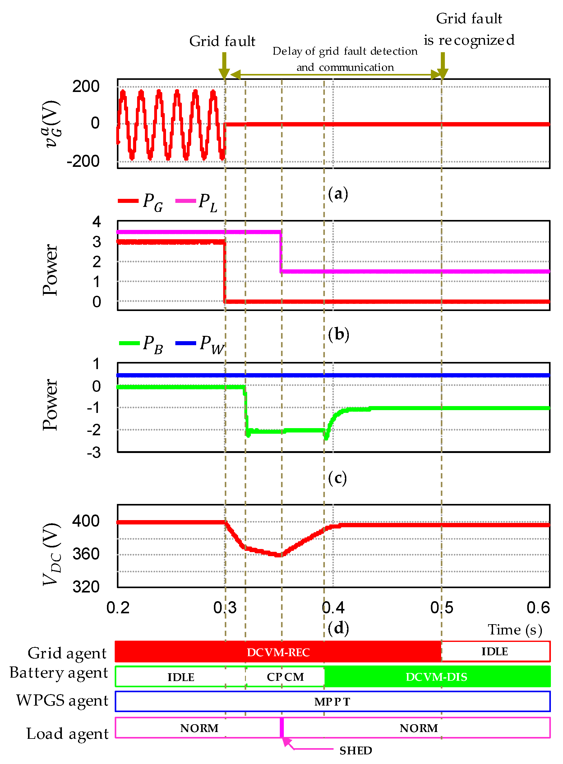
Figure 12 shows the simulation results of the proposed DCV restoration algorithm by the battery agent without SHED in the presence of delay in grid fault detection and communication. Before the grid fault, the DCV control and system power balance is taken over by the grid agent. Meanwhile, the battery agent is in the IDLE mode and the WPGS agent works with the MPPT mode. It is assumed that the grid has a fault at t = 0.3 s and GO and all the system agents cannot instantly recognize it due to delay in grid fault detection and communication. In this condition, the grid agent still works with DCVM-REC while the battery is in IDLE mode. As a result, the DCV decreases rapidly because of power imbalance as can be seen in Figure 12c. However, according to the proposed DCV restoration algorithm in Figure 7, the battery agent executes CPCM and DCVM-DIS in turn to restore the DCV to the nominal value of 400 V. When the grid fault is detected at t = 0.5 s, the operation of the grid agent is switched into IDLE, and the battery agent continuously controls the DCV by DCVM-DIS.
Figure 13 shows the simulation results of the proposed DCV restoration algorithm by the battery agent with SHED under the delay in grid fault detection and communication. The algorithm operates similarly to Figure 12. Only the difference is to apply SHED when the DCV cannot be restored with CPCM. It is shown in Figure 13c that the DCV still decreases even when the battery agent operates with CPCM. As soon as the DCV reaches V f a u l t m i n , the load agent triggers SHED to support the DCV restoration. Once the DCV ceases decreasing, the battery agent executes CPCM and DCVM-DIS in turn to restore the DCV completely to the nominal value of 400 V.
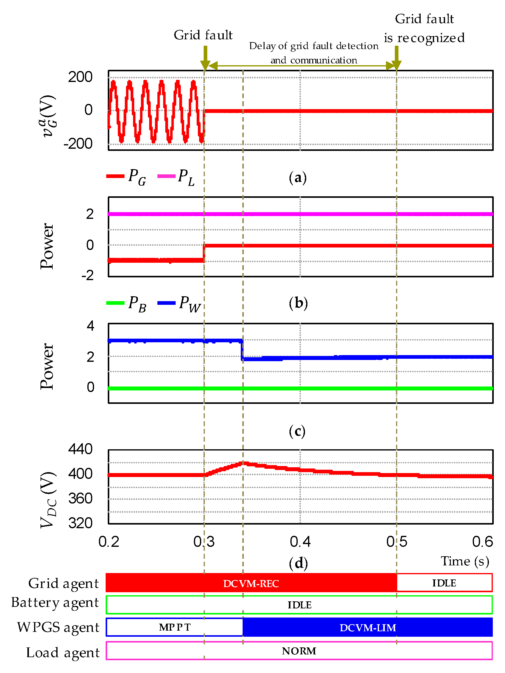
Figure 14 shows the simulation results of the proposed DCV restoration algorithm by the WPGS agent in the presence of delay in grid fault detection and communication. Before the grid fault, the WPGS agent operates with the MPPT mode, the battery is in IDLE, and the DCV is regulated to 400 V with DCVM-INV by the grid agent. As before, it is assumed that the grid has a fault at t = 0.3 s, and GO and all the system agents cannot instantly recognize it due to delay in grid fault detection and communication. This results in the rapid increase of the DCV due to supply–demand power imbalance. However, even in this case, the WPGS agent can effectively restore the DCV with DCVM-LIM by using the proposed DCV restoration algorithm in Figure 7. Once the grid fault is detected at t = 0.5 s, the operation of grid agent is switched into IDLE, and the WPGS agent continuously controls the DCV by DCVM-LIM.
Figure 15 and Figure 16 shows the simulation results for the grid recovery identification under communication failure by the battery agent and WPGS agent, respectively. In Figure 15, the DCV is regulated with DCVM-CHA by the battery agent before the grid is recovered. Even if the grid is recovered at t = 0.2 s, the battery agent cannot recognize it under the communication failure, keep operating with DCVM-CHA. To prevent this situation, the grid agent activates the SCCM to inject a special current pattern (square wave with frequency of 20 Hz) to DC-link. Based on the proposed grid recovery identification algorithm in Figure 8b, the battery current waveform is analyzed to identify the grid recovery by detecting current pattern. The grid recovery can be detected in 0.6 s to ensure the reliable detection under the effect of wind power and load demand variations as can be shown in Figure 15c and Figure 15d. When the battery agent recognizes the grid recovery, the battery agent stops the operation DCVM-CHA to release the authority of DCV control to the grid agent. As a result of ceasing the DCV control, the DCV varies instantly according to supply–demand power balance in DCMG. By sensing this DCV variation, the grid agent can switch the operation SCCM into DCVM-INV to restart the DCV regulation under the communication failure.
In Figure 16, the DCV is regulated with DCVM-LIM by the WPGS agent before grid is recovered. By using the similar procedure, the WPGS can identify the grid recovery by the proposed grid recovery identification algorithm. Then, the WPGS agent switches the operation DCVM-LIM into MPPT to release the authority of DCV control to the grid agent. As a result, it is confirmed from the simulation results that the grid recovery can be detected by using the proposed scheme even under the communication failure irrespective of the variations of wind and load power. In addition, the DCV can be stably regulated without any conflict in the DCV control by two voltage control sources at the same time.

6. Experimental Results

In order to verify the feasibility of the PMS and the reliability of the proposed control strategies in practice, the experiments have been conducted using a laboratory testbed system. Figure 17 shows the configuration of a laboratory DCMG system which consists of three power converters for the connections with the grid, battery, and WPGS. For the grid agent, a bidirectional AC/DC converter which is connected to 3-phase grid through Y-Δ transformer and LCL filters, is employed to exchange the power between the grid and DC-link. In the WPGS agent, a PMSG coupled with an induction machine is used to emulate the wind turbine. The developed power of the WPGS agent is adjusted by controlling the rotating speed of the induction machine through the induction machine drive system. The output power of PMSG is transferred to DC-link by a unidirectional AC/DC converter. In this study, the DSP TMS320F28335 is used to control the converters. The detailed information of the experimental rig can be seen in Figure 2.

6.1. Grid-connected Case

Figure 18 shows the experimental results for system operation in the grid-connected mode by using MAS-based distributed control under the variations of load and wind power. Figure 18a shows DCMG operation under load variation. Initially, the grid agent operates with DCVM-REC to supply the power of 1.2 kW from the grid to DCMG. As the load demand is increased suddenly from 1.2 kW to 2.8 kW, the grid agent increases supplied power from the grid to DCMG to ensure supply–demand power balance. Similar to the simulation result in Figure 10, as the grid supplied power reaches the maximum exchange power of 2 kW, the grid agent switches the operation into CPCM, and sends the data ( G c t r l = 0 ) to other agents. After receiving the data, the battery agent switches the operation into DCVM-DIS to compensate for the deficit power.
Figure 18b shows the system behavior under wind power variation. Before the variation, the WPGS agent works with the MPPT mode, and the grid agent operates with DCVM-REC to supply the power from the grid to DCMG. When the wind power increases beyond the load demand, the grid agent switches the operation DCVM-REC into DCVM-INV to inject the surplus power to the grid. As can be seen from Figure 18, the DCV is stably regulated at 400 V by using the MAS-based distributed control in spite of the variations of load demand and wind power. In these results, Figure 18a corresponds to the instant of t = 1 s in the simulation result of Figure 10, and Figure 18b corresponds to the instant of t = 2.5 s in Figure 10.

6.2. Islanded Case

Figure 19 shows the experimental results for MAS-based distributed control during the transition from the grid-connected to the islanded mode, and vice versa. Figure 19a illustrates DCMG operation for the transition from the grid-connected to islanded mode due to grid fault. Before the grid fault occurs, the system power balance is well maintained by the grid agent. At the instant of grid fault, the battery agent starts the operation DCVM-DIS to compensate for the deficit power caused by the absence of grid. Consequently, the DCV is reliably maintained at 400 V. Figure 19b shows the results for the transition from the islanded to grid-connected mode. Before the grid is recovered, the battery agent maintains the DCV at the nominal value by DCVM-CHA to absorb the surplus power of 0.8 kW. Without communication problems, as soon as the grid is recovered, the battery agent stops the operation DCVM-CHA. Instead, the grid agent activates DCVM-INV to regulate the DCV stably by injecting the surplus power to the grid. These experimental results correspond to the simulation results at t = 1 s and t = 3.5 s in Figure 11 and validate the feasibility of the PMS by using MAS-based distributed control.

6.3. Case of Communication Problems

This Section presents the experimental results of the proposed DCV restoration and grid recovery identification.
Figure 20a and Figure 20b show the results of the proposed DCV restoration under the delay in grid fault detection and communication by battery agent without SHED and with SHED, respectively. In Figure 20a, the DCV is controlled by the grid agent while the battery agent is in IDLE mode before the grid fault. At the instant of the grid fault, according to the proposed DCV restoration algorithm in Figure 7, the battery agent executes CPCM and DCVM-DIS in turn to restore the DCV, which coincides well with Figure 12 in the simulation. Similar to Figure 13 in the simulation, the proposed DCV restoration algorithm executes CPCM by the battery agent, SHED by the load agent, and DCVM-DIS by the battery agent in turn to regulate the DCV stably. Figure 20c shows the results of the proposed DCV restoration by the WPGS agent under the delay in grid fault detection and communication. Before the grid fault, the DCV is regulated at 400 V with DCVM-REC by the grid agent. When the grid has a fault and the battery cannot be used to control the DCV, the WPGS agent intervenes to take a role of DCV regulation as shown in Figure 20c.
All the experimental results are matched well with the simulations in Figure 12 through Figure 14, which confirms the feasibility of the DCV restoration algorithm.
Figure 21 shows the experimental results of the grid recovery identification scheme under the communication failure by the battery agent in Figure 21a and by the WPGS agent in Figure 21b, respectively. In Figure 21a, the DCV is regulated with DCVM-CHA by the battery agent before the grid recovery. Once the grid is recovered, the battery agent can detect the grid recovery by using the proposed grid recovery identification scheme and switches the operation into IDLE mode. Instead, the DCV regulation is taken over by the grid agent with DCVM-INV. In Figure 21b, if the grid is recovered when the WPGS agent controls the DCV, the WPGS agent identifies the grid recovery, and switches the operation into the MPPT mode. Similarly, the DCV regulation is taken over by the grid agent from this instant. These results also accord well with the simulation results in Figure 15 and Figure 16.
It is confirmed that the grid recovery can be effectively detected by using the proposed scheme even under communication failure in the presence of the disturbance such as load power variation. As a result, the DCV can be well regulated to the nominal value without any conflict in the DCV control by two voltage control sources.
In case of the grid fault, the DCV can be restored to the nominal value in 0.1~0.2 s in the simulation results of Figure 12–14, and in 0.2~0.5 s in the experimental results of Figure 20, depending on the communication speed, the converter control dynamics, and DC link capacitance. In both the simulation and experiment, the maximum variation of the DCV during restoration process is obtained as Δ V D C / V D C = 40 400 · 100 % = 10 % as shown in Figure 13 and Figure 20b.
In case of the grid recovery, the grid recovery can be detected within 0.6 s even under the communication failure as shown in both the simulation and experiment of Figure 15, Figure 16, and Figure 21. The maximum variation of the DCV during detection process is Δ V D C / V D C = 10 400 · 100 % = 2.5 % .

7. Conclusions

For the purpose of enhancing the reliability of DCMG and ensuring the system power balance under various conditions, this paper has presented an improved PMS for MAS-based distributed control of DCMG under communication network problems. The main contributions of this paper can be summarized as follows:
i)
A MAS-based distributed control technique has been developed for PMS of DCMG including four agents of the grid, WPGS, battery, and load. In the PMS, by investigating the information obtained from both the local measurements and the neighboring agents via communication lines, all the agents determine not only optimal operating modes for local controllers but also the proper information to be transmitted in order to guarantee the system power balance under various conditions. By using this control scheme, the drawbacks of the existing centralized and decentralized controls are eliminated. In particular, the control mode of the agents can be determined locally without CC, which contributes to avoid the common single point of failure as in the centralized control. Since each agent is controlled by its own local controller, the computational burden is shared by local controllers. In addition, the problem related to communication failure can be avoided by using the proposed reliability improvement algorithm. As compared to the decentralized control, the problems related to the lack of exchanged information can be solved by means of communication network.
ii)
In order to deal with the system power imbalance caused by the delay in grid fault detection and communication, the DCV restoration algorithm is proposed in this paper. By using this scheme, as soon as abnormal level of the DCV is detected, the DCV can be restored stably to the nominal value irrespective of unbound time delay even under the communication network problems, which contributes to prevent the system malfunction and collapse of DCMG.
iii)
To recognize the grid recovery reliably even under communication failure, the grid recovery identification algorithm is introduced in this study. By detecting the frequency of the current pattern on the DC-link, the battery and WPGS agents can effectively identify the grid recovery even in the presence of communication failure. Therefore, the conflict in the DCV control by different voltage control sources can be avoided.
In order to validate the feasibility of the PMS and the proposed schemes, the simulations based on PSIM and the experiments based on the laboratory DCMG testbed have been carried out. In the experimental setup, the WPGS is emulated by coupled PMSM-induction machine. Comprehensive simulation and experimental results have proven the usefulness of the PMS and the proposed reliability improvement schemes under various conditions, especially, under communication network problem. As a result, the proposed DCV restoration and grid recovery identification schemes can contribute to enhance the reliability of DCMG system.

Author Contributions

T.V.N. and K.-H.K. conceived the main concept of the control structure and developed the entire system. T.V.N. carried out the research and analyzed the numerical data with guidance from K.-H.K. T.V.N. and K.-H.K. collaborated in the preparation of the manuscript. All authors have read and agreed to the published version of the manuscript.

Funding

This study was supported by the Advanced Research Project funded by the SeoulTech (Seoul National University of Science and Technology).

Conflicts of Interest

The authors declare no conflict of interest.

Abbreviation

ACAlternating current
ACMGAC microgrid
CCCentral controller
CPCMConstant power control mode
CVCMConstant voltage control mode
DCDirect current
DCMGDC microgrid
DCVDC-link voltage
DCVMDC-link voltage control mode
DCVM-CHADC-link voltage control mode by battery charging
DCVM-DISDC-link voltage control mode by battery discharging
DCVM-INVDC-link voltage control mode by inverter mode of grid agent
DCVM-LIMDC-link voltage control mode by limiting output power of WPGS
DCVM-RECDC-link voltage control mode by converter mode of grid agent
DGDistributed generation
ESSEnergy storage system
GOGrid operator
MASMultiagent system
MPPTMaximum power point tracking
PMSPower management strategy
PMSGPermanent magnet synchronous generator
RECOLoad reconnection
RESRenewable energy source
SCCMSpecial current control mode
SHEDLoad shedding
SOCState of charge
WPGSWind power generation system
NORMNormal load state
CBattery rated capacity
cos φ Power factor of induction machine
C D C DC-link capacitance
F B 1 , F B 2 Flags in control strategy of battery agent
f G Frequency of special current pattern for grid identification algorithm
f G Detected frequency for grid identification algorithm
F G 1 , F G 2 , F G 3 Flags in control strategy of grid agent
F W Flag in control strategy of WPGS agent
i G a a-phase grid current
I B Battery current
I B 1 Battery current with special current pattern
I B 2 Output of high pass filter
G c t r l , B c t r l , W c t r l Indications of DCV control ability by grid, battery, and WPGS agents
G s t a t e State of grid
K e Voltage constant of PMSG
n G e n m a x Rated speed of wind turbine generator
n I n d r a t e d Rated speed of induction machine
P B Output power of battery agent
P B ,   c h a m a x , P B ,   c h a r e q Maximum and required battery charging power
P B ,   d i s m a x , P B ,   d i s r e q Maximum and required battery discharging power
P G Output power of grid agent
P G , i n v m a x , P G , i n v r e q Maximum and required power injected to the grid from DCMG
P G , r e c m a x , P G , r e c r e q Maximum and required power supplied from the grid to DCMG
P G e n r a t e d Rated power of PMSG
P I n d r a t e d Rated power of induction machine
P L ,   P L 1 , P L 2 , P L 3 Total load power, and power of load 1, load 2, load 3
P W Output power of WPGS agent
P W L Supply-demand power relationship
S O C m a x , S O C m i n Maximum and minimum battery state of charge
T s h e d Time delay for load shedding
v G a a-phase grid voltage
V B , V B m a x Battery voltage and maximum battery voltage
V D C , V D C n o m DCV, nominal DCV
V D C , f a u l t m a x ,   V D C , f a u l t T H 1 ,   V D C , f a u l t T H 2 ,   V D C , f a u l t m i n DCV thresholds for grid fault case
V D C , r e c o m a x ,   V D C , r e c o m i n DCV thresholds for grid recovery case
V I n d r a t e d Rated voltage of induction machine

References

  1. Hatziargyriou, N.; Asano, H.; Iravani, R.; Marnay, C. Microgrids. IEEE Power Energy Mag. 2007, 5, 78–94. [Google Scholar] [CrossRef]
  2. Farrokhabadi, M.; Koenig, S.; Canizares, C.A.; Bhattacharya, K.; Leibfried, T. Battery Energy Storage System Models for Microgrid Stability Analysis and Dynamic Simulation. IEEE Trans. Power Syst. 2018, 33, 2301–2312. [Google Scholar] [CrossRef]
  3. Mohammadi, F.; Nazri, G.-A.; Saif, M. A Bidirectional Power Charging Control Strategy for Plug-in Hybrid Electric Vehicles. Sustainability 2019, 11, 4317. [Google Scholar] [CrossRef] [Green Version]
  4. Sanjeev, P.; Padhy, N.P.; Agarwal, P. Peak Energy Management Using Renewable Integrated DC Microgrid. IEEE Trans. Smart Grid 2018, 9, 4906–4917. [Google Scholar] [CrossRef]
  5. Mohammadi, F.; Nazri, G.-A.; Saif, M. A New Topology of a Fast Proactive Hybrid DC Circuit Breaker for MT-HVDC Grids. Sustainability 2019, 11, 4493. [Google Scholar] [CrossRef] [Green Version]
  6. Nguyen, T.V.; Kim, K.-H. Power Flow Control Strategy and Reliable DC-Link Voltage Restoration for DC Microgrid under Grid Fault Conditions. Sustainability 2019, 11, 3781. [Google Scholar] [CrossRef] [Green Version]
  7. El-Hendawi, M.; Gabbar, H.A.; El-Saady, G.; Ibrahim, E.-N.A. Control and EMS of a Grid-Connected Microgrid with Economical Analysis. Energies 2018, 11, 129. [Google Scholar] [CrossRef] [Green Version]
  8. Xu, L.; Chen, D. Control and Operation of a DC Microgrid with Variable Generation and Energy Storage. IEEE Trans. Power Deliv. 2011, 26, 2513–2522. [Google Scholar] [CrossRef]
  9. Dragičević, T.; Lu, X.; Vasquez, J.C.; Guerrero, J.M. DC Microgrids-Part I: A Review of Control Strategies and Stabilization Techniques. IEEE Trans. Power Electron. 2016, 31, 4876–4891. [Google Scholar]
  10. Dehkordi, N.M.; Sadati, N.; Hamzeh, M. Fully Distributed Cooperative Secondary Frequency and Voltage Control of Islanded Microgrids. IEEE Trans. Energy Convers. 2017, 32, 675–685. [Google Scholar] [CrossRef]
  11. Gao, L.; Liu, Y.; Ren, H.; Guerrero, J.M. A DC Microgrid Coordinated Control Strategy Based on Integrator Current-Sharing. Energies 2017, 10, 1116. [Google Scholar] [CrossRef] [Green Version]
  12. Kumara, J.; Agarwalb, A.; Agarwala, V. A Review on Overall Control of DC Microgrids. J. Energy Storage 2019, 21, 113–138. [Google Scholar] [CrossRef]
  13. Yazdanian, M.; Mehrizi-Sani, A. Distributed Control Techniques in Microgrids. IEEE Trans. Smart Grid 2014, 5, 2901–2909. [Google Scholar] [CrossRef]
  14. Logenthiran, T.; Naayagi, R.T.; Woo, W.L.; Phan, V.-T.; Abidi, K. Intelligent Control System for Microgrids Using Multiagent System. IEEE J. Emerg. Sel. Topics Power Electron. 2015, 3, 1036–1045. [Google Scholar] [CrossRef]
  15. Qi, X.; Luo, Y.H.; Zhang, Y.; Zhou, G.; Wei, Z. Novel Distributed Optimal Control of Battery Energy Storage System in an Islanded Microgrid with Fast Frequency Recovery. Energies 2018, 11, 1955. [Google Scholar] [CrossRef] [Green Version]
  16. Dehkordi, N.M.; Sadati, N.; Hamzeh, M. Distributed Robust Finite-Time Secondary Voltage and Frequency Control of Islanded Microgrids. IEEE Trans. Power Syst. 2017, 32, 3648–3659. [Google Scholar] [CrossRef]
  17. Dou, C.; Zhang, Z.; Yue, D.; Zheng, Y. MAS-Based Hierarchical Distributed Coordinate Control Strategy of Virtual Power Source Voltage in Low-Voltage Microgrid. IEEE Access 2017, 5, 11381–11390. [Google Scholar] [CrossRef]
  18. Lai, J.; Lu, X.; Li, X.; Tang, R.-L. Distributed Multiagent-Oriented Average Control for Voltage Restoration and Reactive Power Sharing of Autonomous Microgrids. IEEE Access 2018, 6, 25551–25561. [Google Scholar] [CrossRef]
  19. Morstyn, T.; Hredzak, B.; Agelidis, V.G. Communication Delay Robustness for Multi-Agent State of Charge Balancing Between Distributed AC Microgrid Storage Systems. In Proceedings of the 2015 IEEE Conference on Control Applications (CCA), Sydney, Australia, 21–23 September 2015; pp. 181–186. [Google Scholar]
  20. Chen, F.; Chen, M.; Li, Q.; Meng, K.; Guerrero, J.M.; Abbott, D. Multiagent-Based Reactive Power Sharing and Control Model for Islanded Microgrids. IEEE Trans. Sustain. Energy 2016, 7, 1232–1244. [Google Scholar] [CrossRef] [Green Version]
  21. Li, Q.; Chen, F.; Chen, M.; Guerrero, J.M.; Abbott, D. Agent-Based Decentralized Control Method for Islanded Microgrids. IEEE Trans. Smart Grid 2016, 7, 637–649. [Google Scholar] [CrossRef] [Green Version]
  22. Dou, C.; Yue, D.; Zhang, Z.; Ma, K. MAS-Based Distributed Cooperative Control for DC Microgrid Through Switching Topology Communication Network with Time-Varying Delays. IEEE Syst. J. 2019, 13, 615–624. [Google Scholar] [CrossRef]
  23. Lai, J.; Zhou, H.; Hu, W.; Lu, X.; Zhong, L. Synchronization of Hybrid Microgrids with Communication Latency. Math. Probl. Eng. 2015, 2015, 1–10. [Google Scholar] [CrossRef] [Green Version]
  24. Dou, C.; Yue, D.; Zhang, Z.; Guerrero, J.M. Hierarchical Delay-Dependent Distributed Coordinated Control for DC Ring-Bus Microgrids. IEEE Access 2017, 5, 10130–10140. [Google Scholar] [CrossRef]
  25. Dou, C.; Yue, D.; Guerrero, J.M.; Xie, X.; Hu, S. Multiagent System-Based Distributed Coordinated Control for Radial DC Microgrid Considering Transmission Time Delays. IEEE Trans. Smart Grid 2016, 8, 2370–2381. [Google Scholar] [CrossRef] [Green Version]
  26. Zhang, R.; Hredzak, B. Distributed Finite-Time Multiagent Control for DC Microgrids with Time Delays. IEEE Trans. Smart Grid 2018, 10, 2692–2701. [Google Scholar] [CrossRef]
  27. Zhang, Z.; Dou, C.; Yue, D.; Zhang, B.; Li, F. Neighbor-Prediction-Based Networked Hierarchical Control in Islanded Microgrids. Int. J. Electr. Power Energy Syst. 2019, 104, 734–743. [Google Scholar] [CrossRef]
  28. Gaeini, N.; Amani, A.M.; Jalili, M.; Yu, X. Cooperative Secondary Frequency Control of Distributed Generation: The Role of Data Communication Network Topology. Int. J. Electr. Power Energy Syst. 2017, 92, 221–229. [Google Scholar] [CrossRef]
  29. IEEE. IEEE Standard for Interconnection and Interoperability of Distributed Energy Resources with Associated Electric Power Systems Interfaces, IEEE Std.1547; IEEE: New York, NY, USA, 2018. [Google Scholar]
  30. Tran, T.V.; Yoon, S.-J.; Kim, K.-H. An LQR-Based Controller Design for an LCL-Filtered Grid-Connected Inverter in Discrete-Time State-Space under Distorted Grid Environment. Energies 2018, 11, 2062. [Google Scholar] [CrossRef] [Green Version]
  31. Wu, X.; Panda, S.K.; Xu, J. Development of a New Mathematical Model of Three Phase PWM Boost Rectifier Under Unbalanced Supply Voltage Operating Conditions. In Proceedings of the 2006 37th IEEE Power Electronics Specialists Conference, Jeju, Korea, 18–22 June 2006; pp. 1–7. [Google Scholar]
  32. Hegazy, O.; Mierlo, J.V.; Lataire, P. Control and Analysis of an Integrated Bidirectional DC/AC and DC/DC Converters for Plug-in Hybrid Electric Vehicle Applications. J. Power Electron. 2011, 11, 408–417. [Google Scholar] [CrossRef] [Green Version]
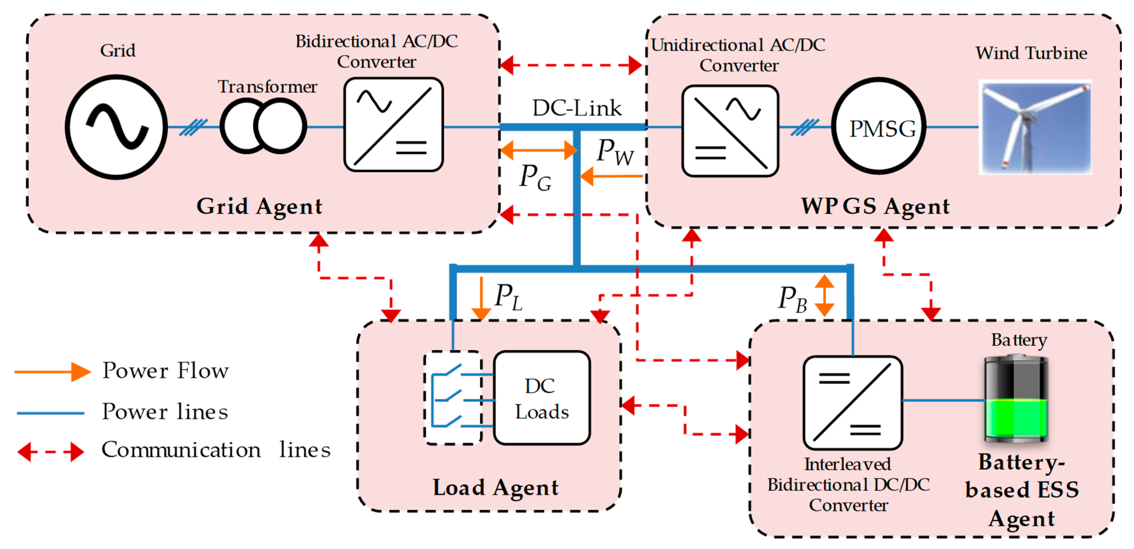
Figure 1. DCMG with MAS-based distributed control.
Sustainability 12 00122 g001
Figure 2. System communication topology.
Sustainability 12 00122 g002
Figure 3. Control strategy of grid agent.
Sustainability 12 00122 g003
Figure 4. Control strategy of battery agent.
Sustainability 12 00122 g004
Figure 5. Control strategy of WPGS agent.
Sustainability 12 00122 g005
Figure 6. Control strategy of load agent.
Sustainability 12 00122 g006
Figure 7. DCV restoration algorithms. (a) By battery agent; (b) By load agent; (c) By WPGS agent.
Sustainability 12 00122 g007
Figure 8. Control strategies for reliability improvement of DCMG during grid recovery. (a) Special current pattern generation by grid agent; (b) Grid recovery identification algorithm of battery and WPGS agents by frequency detection.
Sustainability 12 00122 g008
Figure 9. Illustration of grid recovery identification algorithm by frequency detection. (a) Output power of grid agent; (b) Battery current without special current pattern; (c) Battery current with special current pattern; (d) Output of high pass filter; (e) Output of zero-crossing detection; (f) Generated frequency by the grid agent and detected frequency by grid recovery identification algorithm.
Sustainability 12 00122 g009
Figure 10. Simulation results for grid-connected mode. (a) a-phase grid voltage and current; (b) Output power of each agent; (c) Battery SOC; (d) DCV.
Sustainability 12 00122 g010
Figure 11. Simulation results for islanded mode. (a) a-phase grid voltage and current; (b) Output power of each agent; (c) Battery SOC; (d) DCV.
Sustainability 12 00122 g011
Figure 12. Simulation results of the proposed DCV restoration by battery agent without SHED. (a) a-phase grid voltage; (b) Output power of grid agent and total load power; (c) Output power of battery agent and WPGS agent; (d) DCV.
Sustainability 12 00122 g012
Figure 13. Simulation results of the proposed DCV restoration by battery agent with SHED. (a) a-phase grid voltage; (b) Output power of grid agent and total load power; (c) Output power of battery agent and WPGS agent; (d) DCV.
Sustainability 12 00122 g013
Figure 14. Simulation results of the proposed DCV restoration by WPGS agent. (a) a-phase grid voltage; (b) Output power of grid agent and total load power; (c) Output power of battery agent and WPGS agent; (d) DCV.
Sustainability 12 00122 g014
Figure 15. Simulation results for the grid recovery identification under communication failure by battery agent. (a) DCV; (b) Output power of grid agent; (c) Load power; (d) Output power of WPGS; (e) Battery current.
Sustainability 12 00122 g015
Figure 16. Simulation results for the grid recovery identification under communication failure by WPGS agent. (a) DCV; (b) Output power of grid agent; (c) Load power; (d) WPGS current.
Sustainability 12 00122 g016
Figure 17. Configuration of the experimental DCMG system.
Sustainability 12 00122 g017
Figure 18. Experimental results for grid-connected mode. (a) Load variation; (b) Mode transition of grid agent from DCVM-REC to DCVM-INV.
Sustainability 12 00122 g018
Figure 19. Experimental results for islanded mode. (a) Transition from grid-connected to islanded mode; (b) Transition from islanded mode to grid-connected mode.
Sustainability 12 00122 g019
Figure 20. Experimental results of the proposed DCV restoration. (a) By battery agent without SHED; (b) By battery agent with SHED (c) by WPGS agent.
Sustainability 12 00122 g020aSustainability 12 00122 g020b
Figure 21. Experimental results for the grid recovery identification under communication failure. (a) By battery agent; (b) By WPGS agent.
Sustainability 12 00122 g021
Table 1. Detailed description of exchange data.
Communication Line Exchange Data Data TypeData Information
1 P G , r e c m a x DoubleMaximum power supplied from grid to DCMG
P G , i n v m a x DoubleMaximum power injected to grid from DCMG
G s t a t e Binary00: Grid has fault.
11: Grid is recovered.
01: Grid is being normal.
2, 3, 4 G c t r l Binary1: Grid agent is able to control DCV.
0: Grid agent is not able to control DCV.
5, 6 B c t r l   Binary1: Battery agent is able to control DCV.
0: Battery agent is not able to control DCV.
7 W c t r l Binary1: WPGS agent is able to control DCV.
0: WPGS agent is not able to control DCV.
8, 9 P W L Binary1: Load power is greater than wind power ( P L P W ).
0: Load power is smaller than wind power ( P L < P W ).
10 P L Double Load power
Table 2. System parameters of DCMG.
Unit ParameterSymbolValue
Grid operatorMaximum power supplied from grid to DCMG P G , r e c m a x 2 kW
Maximum power injected to grid from DCMG P G , i n v m a x 2 kW
Grid agentGrid voltage V G r m s 220 V
Grid frequency F G 60 Hz
Frequency for SCCM f G 20 Hz
Transformer Y / Δ T380/220 V
Local controller: Digital signal processor (DSP) TMS320F28335--
WPGS agentInduction machineRated power P I n d r a t e d 3 kW
Rated voltage V I n d r a t e d 380 V
Rated speed n I n d r a t e d 1425 min−1
Power factorcos φ 0.85
Permanent magnet synchronous generator (PMSG)Stator resistance R S 0.64 Ω
dq-axis inductance L d q 0.82 mH
Number of pole pairs P 6
Inertia J 0.111 kgm2
Flux linkage ψ 0.18 Wb
Rated power P G e n r a t e d 3 kW
Maximum speed n G e n m a x 3200 rpm
Voltage constant K e 147 V/Krpm
Predefined level for frequency detection in grid recovery identification algorithmN11
Local controller: DSP TMS320F28335--
Battery agent Maximum discharging power P B , d i s m a x 2 kW
Maximum voltage V B m a x 265 V
Maximum SOC S O C m a x 90 %
Minimum SOC S O C m i n 10 %
Rated capacityC30 Ah
Predefined level for frequency detection in grid recovery identification algorithmN11
Local controller: DSP TMS320F28335--
Load
agent
Power of load 1 P L 1 0.5 kW
Power of load 2 P L 2 1 kW
Power of load 3 P L 3 2 kW
Priority level: load 1 > load 2 > load 3--
Local controller: DSP TMS320F28335--
DC-link Nominal voltage V D C n o m 400 V
Maximum DCV used for grid fault V D C , f a u l t m a x 420 V
First threshold level for DCV used for grid fault V D C , f a u l t T H 1 370 V
Second threshold level for DCV used for grid fault V D C , f a u l t T H 2 390 V
Minimum DCV used for grid fault V D C , f a u l t m i n 360 V
Maximum DCV used for grid recover V D C ,   r e c o m a x 410 V
Minimum DCV used for grid recover V D C , r e c o m i n 390 V
Capacitance C D C 4 mF
Table 3. Operation conditions for simulation test in grid-connected mode.
Operation ConditionsTime (s)
1Load 3 is switched in.1
2Wind power gradually decreases from 0.5 kW to 0.1.5
3Wind power increases from 0 to 2 kW.2
4Wind power increases from 2 kW to 4 kW.2.5
5Load 2 and load 3 are switched out.3
6Battery fault occurs.3.5
Table 4. Operation conditions for simulation test in islanded mode.
Operation ConditionsTime (s)
1Grid fault occurs.1
2Wind power decreases from 2 kW to 1 kW.1.5
3Battery SOC reaches the minimum level.2
4Wind power increases from 1 kW to 2 kW.2.5
5Load 2 is reconnected.3
6Grid is recovered.3.5