Abstract
The tires used constitute an environmental problem that remains unsolved. It is observed that the automotive fleet and therefore the generation of tires increases year after year, so the recovery and reuse processes are insufficient. For several years, the reuse of tires as materials in the construction has been considered, and several techniques have been developed for the construction of retaining walls and road reinforcement. However, to date, their use remains sporadic. This article presents the theoretical and experimental evaluation of a new geotechnical reinforcement system from used tires. This system, suitable for the construction of containment structures and the reinforcement of roads, is characterized by the conformation of cells that do not require other elements apart from the tires and the filling material. A mathematical model was developed to describe the behavior of the system and pullout tests were carried out for validation. The tests were performed with different tire and compacted granular material with different energies. The results allow validating the theoretical model by showing an increase in pullout resistance with the density and number of tires in the arrangement. It is observed that the coincidence between the model and the tests improves as the stiffness of the soil increases, being the degree of compaction fundamental for the operation.
1. Introduction
The final disposal of waste tires is still an environmental problem due to their increasing production and recycling difficulties. It is estimated that between 1400 million and 2900 million tires are produced worldwide each year [1] or 17 × 109 kg [2], and its demand grows approximately 4.3% annually [3,4]. This growth in the generation of old tires is one of the negative consequences of the exponential growth that automotive transport has shown in the last decades, along with air pollution and noise. This growth is associated, among other things, with the globalization of the economy and the urbanization of the population [5]. On one hand, China, the European Union countries, the USA, Japan, and India produce the largest amount of waste tires (about 88% of the total) [6]. On the other hand, there is a difficulty to recycle old tires due mainly to its resistance against mechanical damage and the presence of degradation inhibitor additives and their highly complex structure [1,7,8]. Research estimates that tires take more than 100 years to degrade [8,9]. Due to these difficulties for recycling, most of the old tires are destined to the production of energy [1,3,7,8]. A smaller part is used for the manufacturing of floors and the modification of asphalt concrete and other applications [1,9,10,11].
In Colombia, between 110,000 and 130,000 tons of this material is generated per year, which means about 7 million tires are produced [12]. According to data from 2016, of the tires produced, approximately 2.9 million tires were collected by the system for selective collection and environmental management of used tires, which is equivalent to 4.58 × 10⁹ kg. Of the total collected, 8% were reused, 70% were processed as GCR (Rubber Granule Recycled) or used for civil engineering applications, and 22% were recovered for energy use programs of alternative fuels in cement kilns [13]. In general, the preferred method for the final disposal of tires is the incineration. However, the cement kiln currently used for energy recovery has a capacity to burn 20,000 tons, incinerating about 5530 tons of tires by 2016 [13], or the equivalent of 5.03% of the total amount available per year in the country.
In countries such as the USA, Japan, and the UE, 100% of the waste tires are collected. However, in developing countries, recycling processes are still insufficient. It is estimated that in countries such as Brazil, Colombia, and Mexico, only around 80% is collected [3,13,14]. As part of government policies for sustainable production and consumption, in Colombia, there are regulatory systems for the recovery of batteries, hospital waste, technological equipment (e.g., mobile phones, computers), car batteries, and scrap tires [15]. Colombia relies only on mechanical crushing to produce rubber granules, which currently have a limited and unstable demand, a fact that imposes the need to explore recycling technologies to further expanding the use options for recycled products from tire waste. This makes it necessary to search for applications that allow a massive use of used tires and as an alternative for the use in infrastructure construction.
The use of waste tires in geotechnical engineering has been considered in several ways. Recycled rubber grain (GCR) has been used as a subbase filler, alone or mixed with granular soil, to improve soil engineering properties [16,17,18,19]. They have shown that the advantages of using this mixture lies not only in its low biodegradability, but also in the relationship between the drainage characteristics of the material and the decrease in stability problems generated by the excessive increase in pore pressures. GCR has also been used as filling for retaining walls or embankment shaping [16,19,20,21,22,23,24,25], showing that the addition of tire chips and rim pieces improves the resistance to sand cutting. Applications are also found in the stabilization of liquefiable soils [4].
Another form of use has been as a ground reinforcement, either with the whole tires or strips [26,27,28,29,30,31]. In recent studies [30], researchers discussed the benefits of reinforcing dikes and embankments with the whole tire by running a series of field-level pullout tests to investigate the behavior of waste tire extraction in cell-type arrangements on reinforced soil. The results of these studies concluded significant decreases both in horizontal displacements and in reinforced embankment settlements, relative to unreinforced embankments, as a consequence of the additional strength and rigidity provided by tires.
As an alternative for the final disposal of tires in civil works, this study has proposed an innovative reusing strategy for the use of scrap tires as a geotechnical reinforcement system (RTS). RTS is a special arrangement consisting of several tire rings folded in butterfly form and filled with soil, concrete, or other material that allows adequate compaction. As can be seen in Figure 1, the individual RTS elements are placed sequentially forming a mesh, generating links that allow the transfer of stresses between them. Due to the characteristics of the geometric arrangement, RTS system does not require connectors, there being only a mechanical interaction between them. This ensures to maximize the use of strength of tires and avoids failures that may occur when using screws, rivets, and other connectors that generates stress concentration or are susceptible to corrosion. Patented in Colombia, this RTS system allows the construction of retaining structures, such as the one shown in Figure 2 or in the reinforcement of roads, for the placement of pavements or as erosion control.
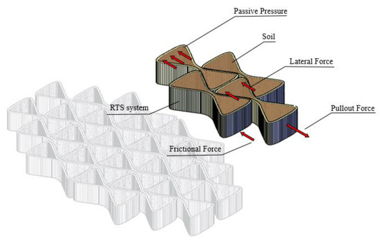
Figure 1.
Reinforcement tire system.
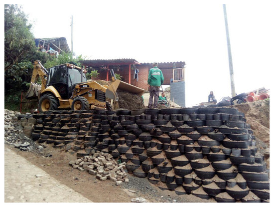
Figure 2.
Prototype wall built in the Municipality of Envigado (Colombia).
The RTS system has proven to be efficient in the construction of retaining walls [32,33,34]. However, it is necessary to properly identify the behavior of the system subject to loads or work forces that allow to adequately identify its performance and complement the work done by [32] and [35]. For the design of mechanically stabilized retaining walls, reinforced embankments and subgrade reinforcement, the most important parameter is the pullout resistance of the reinforcement elements. Although it is known that the soil reinforced with tires (whether from rubber granules or using the whole tire) is currently used, there are only a small number of studies that focus on loading and the deformation behavior of this type of reinforcement material, particularly through pullout laboratory tests [28,35,36]. The tire reinforcement literature has shown that the ultimate tire extraction capacity is 1.25 times that of a geo cell or similar reinforcement material [29].
A concern generated by this type of application is due to the leaching of metals and other components of the tires and their impacts on the soil and groundwater. In general, the use of tires (whole, strips, or granules) in mixture with soil in civil works has been identified as having limited environmental impacts [37,38]. Studies of leaching with strips or granules mixed with soil have shown that the levels of barium, chromium, lead, cadmium, arsenic, and zinc (among others) may be higher than those defined for drinking water, but remain at lower levels than those defined as toxic by authorities such as the EPA [38,39]. It has also been identified that the leaching potential increases when the size of the granules is reduced or when the material is exposed to very acidic environments, which are unlikely in applications of mixes of tires and soils in civil works [39].
This article addresses the theoretical and experimental evaluation of the RTS system described above by pullout tests. Tests with different configurations of tires and granular material compacted with different energies were performed. Likewise, the experiment allows having an approach to the development of a technology that responds to the demands of the recycling market, which allows closing the life cycle of the material or representing reverse logistics in its new use.
2. Materials and Methods
The pullout tests were performed using a loading device consisting of a main box in which the reinforcement elements are placed, the elements are filled with sand, a compression load is applied, and then the element is pulled with an actuator. The pullout tests are schematically shown in Figure 3. The equipment, materials, and test procedure are described in detail below.
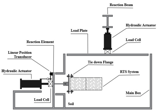
Figure 3.
Pullout test scheme.
2.1. Equipments
According to the scheme in Figure 3, a system was designed for the execution of real scale tests. The system allows the realization of tests on elements of real size and has a capacity of 200 kN of both normal and shear or pullout load. To generate the normal load, the system has a steel beam (I shape), a steel plate, and a hydraulic jack of 250 kN capacity. For the pullout force, an Enerpac telescopic jack RC256 model of 200 kN capacity and a 180 mm travel was used. For force measurement, two load cells of 250 kN capacity, sensitivity of 24,313 mVdc, and for the measurement of displacements, a linear position transducer with a maximum capacity of 200 mm and an accuracy of 0.001 mm were used. The system has a box or tank with internal dimensions 1.2 × 1.2 × 0.7 m. For the data acquisition, a 24-channel system developed for the laboratory center of the University of Medellín was used. The test system is shown in detail in Figure 3 and Figure 4, with the main components of the system.
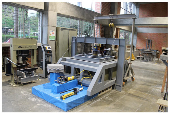
Figure 4.
Overview of the reaction system for pullout tests.
2.2. Materials
Used tires for wheel diameter 330 mm (R-13) with the sidewall were previously removed. According to Table 1, an R-13 tire has an average thickness of 0.78 cm ± 0.14 cm, a height of 17.27 cm ± 1.74 cm, a diameter of 52.99 cm ± 3.71 cm, and a weight of 3.78 kg ± 0.77 kg. These tires have tensile strength with an average of 58.5 kN ± 11.5 kN and an average elongation of 6.7 cm ± 1.8 cm. For the purposes of the tests, a statistical sample of 60 tires was taken.

Table 1.
Properties for characterization of tire rings.
A sand soil that meets the characteristics of fine aggregates for concrete was used in accordance with the Colombian technical specifications and standards. The particle size distribution (standard INV E-213 equivalent to ASTM C 136 - 01) of the material is shown in Figure 5. As observed in Figure 6a,b, the maximum density and optimum moisture content for a compaction test (INV E-141/ASTM D-698 and INV E-142/ASTM D-1557) was 19.71 kPa and 10.20% for the standard effort, and 20,61 kPa and 9.40% for modified effort, respectively. Additionally, a drained direct shear test (INV E-154/ASTM D3080-90) with normal stress ranges between 50 kPa and 200 kPa was executed, obtaining a drained friction angle of 43.0° and an effective cohesion of 8.9 kPa (see Figure 7). Table 2 shows the results of the characterization tests.
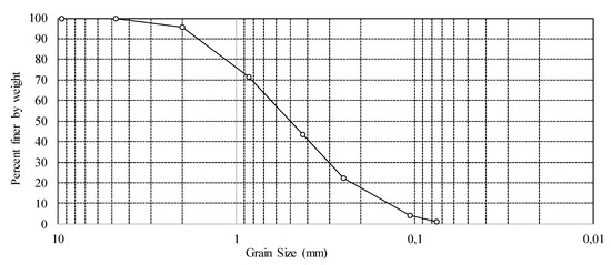
Figure 5.
Granulometric distribution of the sand for tests.
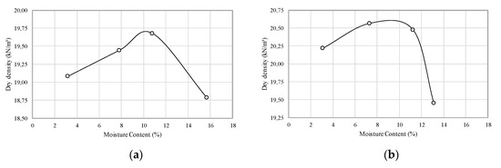
Figure 6.
Proctor compaction test (a) Standard Proctor; (b) Modified Proctor.
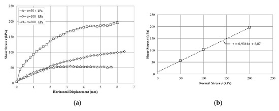
Figure 7.
Direct shear test (a) Stress vs. horizontal displacement plot; (b) Shear Stress envelope.
Table 2.
Physical Properties of the material.
2.3. Procedure
In performing the pullout test, three tire arrangements were used as shown in Figure 8. In the first arrangement, which consists of one unit and shown in Figure 8a, the individual resistance of each element was determined. The second arrangement consists of six units and is shown in Figure 8b. The third part consisting of five units is shown in Figure 8c. The second and third arrangement evaluate the effect of the confinement of the lateral elements on the pullout load.
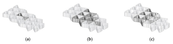
Figure 8.
Arrangements of the reinforcement system used in the tests: (a) one element, (b) five elements, (c) six elements.
As shown in Figure 9, the tires were configured using a mold specially manufactured for this purpose following the below process:
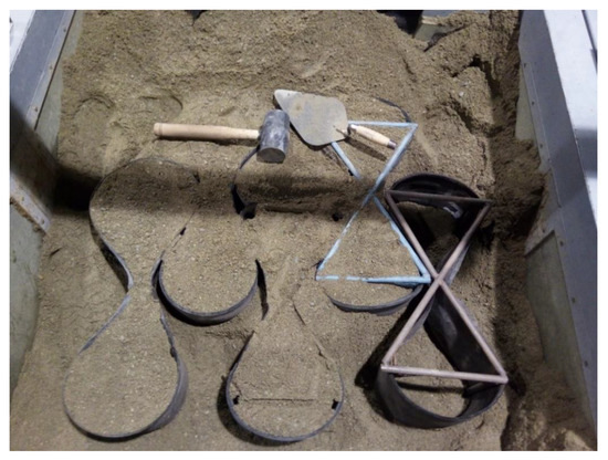
Figure 9.
Reinforcement system installation.
- Treads were configured in the form of a butterfly using the metal mold and minor hand tools.
- Provisional ties were placed if necessary.
- Rows are formed with the butterflies folded, forming the interlocking system that is shown.
- The empty spaces were filled with compacted sand.
- The rest of the chamber was filled with compacted sand (Figure 9).
Once the filling process is completed, the sand surface is leveled and the load transfer plate is placed (Figure 4). By means of the telescopic jack, a force is applied between the plate and the vertical reaction frame in order to generate an increase in normal stresses. Then, the pullout process is carried out by means of the hollow plunger hydraulic actuator. During the pullout process, the displacement of the pulled element was measured with the linear position transducer.
Several experiments were performed in which the normal stress parameters and the density of the sand were varied. The trial matrix includes the execution of two experimental campaigns shown in Table 3.
Table 3.
Matrix of laboratory tests.
2.4. Theoretical Pullout Test
The results obtained in the tests were compared with analytical estimates of the pullout load of the elements, determined from an approach based on the limit equilibrium method described below. As shown in Figure 10, which represents the central elements highlighted in Figure 8b, the pullout load Ti required for the complete mobilization of the reinforcement element depends on the friction of fill and interaction with other elements. Considering the configuration shown in Figure 10 and assuming the elements as rigid bodies, that lateral displacements are restricted by confinement, and principles of statics the pulling load (Ti) can be represented by the following equation:
where, FF = Friction force caused by the ground contact on the upper and lower surface of the element; = Passive pressure generated over a unit cross-sectional area, which tends towards a passive condition; = Horizontal components of the lateral reaction forces by contact with neighboring elements.
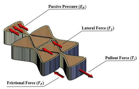
Figure 10.
Components of acting forces in the system.
Ti is the ultimate pullout load required for the complete mobilization of the RTS element which depends on the friction on the upper and lower faces, the reactions with the neighboring elements, and the pushing force between the fill and the rim. Figure 8a shows the simplest configuration that can be obtained for RTS. However, the magnitude of lateral forces (FL) is related to the arrangement of rows in the arrangement and tends to gradually increase with the amount of elements. With the inductive method, it can be verified that:
where, n = Number of rows of RTS
where, z is the thickness of the fill above the RTS, h2 is the height of the rim, A is the area of the butterfly’s triangles, q is an overload evenly distributed at the top of the fill [F/L2], W is the width of the base of the triangle that forms the butterfly (as shown in Figure 10), and Kp is the coefficient of Rankine’s passive earth pressure.
3. Results
Two pullout test campaigns were executed for a total of 27 tests. In campaign 1, tests were carried out with the objective of determining the pullout force with variation of the normal force. For campaign 2, in addition to the magnitude of the extraction force, a linear position transducer was used to measure the displacements of the arrangements considered according to Figure 3, which determined the force-displacement curves of the tire system. Table 4 and Table 5 display a summary of the test results for each campaign.
Table 4.
Pullout Test Results: Experimental Campaign 1.
Table 5.
Pullout Test Results: Experimental Campaign 2.
For the results of the second test campaign, Figure 11, Figure 12 and Figure 13 show the results for loose sand, and Figure 14, Figure 15 and Figure 16 for dense sand. For analyzes, the following study scenarios will be considered:
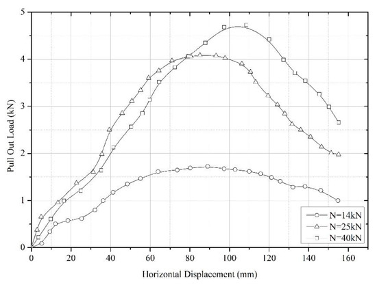
Figure 11.
Pullout test results based on a tire in loose sand.
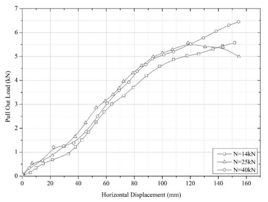
Figure 12.
Pullout test results based on five tires in loose sand.
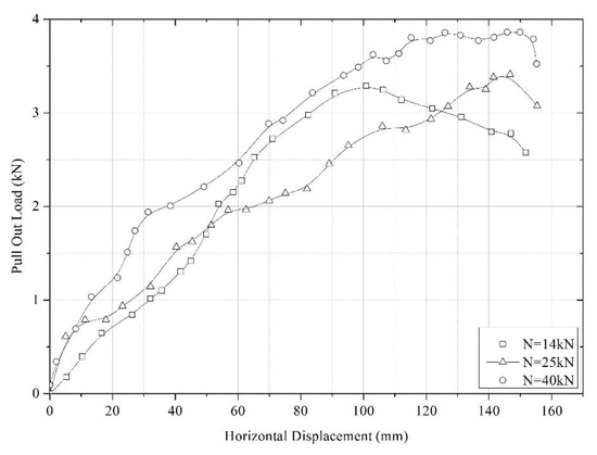
Figure 13.
Pullout test results with arrangement of six tires in loose sand.
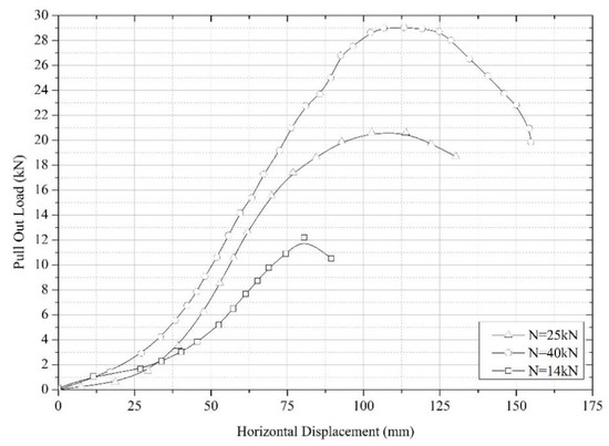
Figure 14.
Pullout test results based on a tire and compacted sand: Proctor modified.
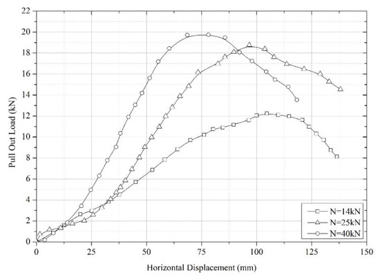
Figure 15.
Pullout test results based on a tire and compacted sand. Standard proctor effort.

Figure 16.
Pullout test results based on five tires and compacted sand. Modified proctor effort.
- Tire arrangements 1 × 1, 1 × 3 and 1 × 6, loose density.
- 1 × 1 tire arrangements, standard and modified compact density.
- 1 × 3 tire arrangements, modified compact density.
4. Discussion of Results
As seen in Figure 11 through Figure 16, the maximum pullout load varies with the normal confinement pressure, the type of configuration used, and the degree of compaction. The extraction force under a maximum normal confinement pressure of 40 kPa and 0.40 m overload height varied from 1.72 kN for an individual element to 6.44 kN for a five-element configuration in loose sand conditions. Under dense filling conditions, the tire configurations under study generated greater resistance to extraction. It is also observed that the maximum displacements are of the order of 100 mm and are greater for the fully compacted with the modified Proctor energy. The degree of confinement of the tire reinforcement influences its load-deformation behavior. Consequently, the decrease in the resistance to extraction and the corresponding increase in frontal displacement are the result of both a decrease in the resistance of the front wedge and the possible extrusion of the first row of tires, which additionally lose the filling material and end up with excessive deformations. Figure 17 schematically shows the mechanism of mobilization of the resistance of the surrounding soil.
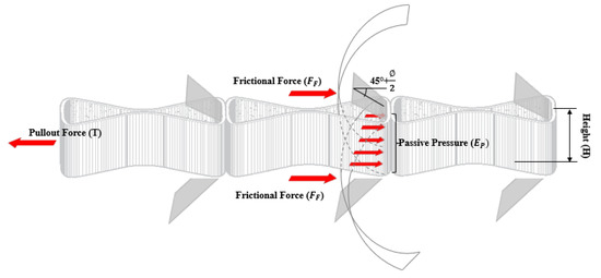
Figure 17.
Pullout resistance mechanism in the reinforcement.
For the individual elements, in campaign 1 for loose sand conditions, the maximum pullout load for this tire configuration subjected to the maximum normal force of 40 kN was 2.97 kN with a corresponding displacement of 158 mm. Under conditions of dense sand, the maximum extraction force was 29.03 kN, with a corresponding displacement of 154 mm. In the second test campaign, for loose sand conditions, the maximum extraction load subjected to the maximum normal force of 40 kN was 4.72 kN, with a corresponding displacement of 155 mm. An increase in the magnitude of pullout force is evidenced as a function of normal force and compaction density. Thus, for example, for a normal force of 40 kN, a resistance of 20.06 kN was obtained for compaction by standard effort and of 29.03 kN for compaction by modified effort.
After evaluating the capacity of the individual elements, pullout tests were carried out in two different arrangements. First, a geometric arrangement of six elements was considered, as shown in Figure 8b. The results obtained are observed in Figure 13, which show that there is no substantial increase in the pullout force when the normal load is increased. It can be seen that the pulling force is greater than that of the individual elements with low confinement efforts, but it is lower when the normal force increases. This behavior is due to the fact that the tensioned element is laterally unconfined since it lacks adjacent units that influence the distribution of the pulling force, a fact that leads to a lateral displacement of the element which prevents it from gaining resistance when increased confinement efforts.
Subsequently, the resistance of a 1 × 3 tire configuration was evaluated, as shown in Figure 8c. In this configuration, the traction element has elements that confine it laterally. With a maximum normal force of 40 kN and loose density in the first campaign, a starting force of 4.07 kN was obtained with a displacement of 176 mm. Under conditions of dense sand, it was 21.84 kN with a displacement of 137 mm. In the second campaign, loose sand condition the maximum load was 6.44 kN with a displacement of 154 mm, but with normal loads of 40 kN, 17.11 kN and 22.19 kN were obtained for standard and modified Proctor, respectively. In this way, it is likely to state that the pullout resistance is influenced by the ability of the sand to expand. This behavior is similar to that reported by [40] for conventional reinforcements placed in dense sands, which is characterized by a configuration of the tires without design arrangements, such as the case under study and joined by polypropylene ropes.
Figure 18 shows the relationships between the normal force applied during the tests and the extraction force necessary to mobilize the starting force of the system. The results show that the values obtained for the arrangements that involve a compaction process are located above the values obtained for loose compaction conditions, which demonstrates that the contact interface between the tires together with an acceptable compaction state of the material are able to mobilize shear strengths greater than loose sand conditions. Linear regressions were established for each fault envelope that relate the shear force and the confinement force. Table 6 shows the regression parameters. As stated earlier, there is a significant difference between the arrangements that involve compaction processes from those that considered a loose state of the sand. For example, it is noted that a compacted 1 × 1 arrangement has a value similar to that presented by the filler alone. A different case can be inferred from a 1 × 6 arrangement condition, whose lateral unconfined condition induces an almost flat envelope in which each of the elements behaves independently in the transmission of the pulling force.
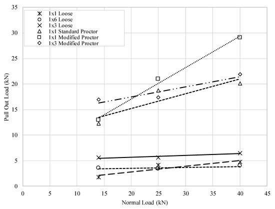
Figure 18.
Failure envelopes between Normal Force and Pullout Force.
Table 6.
Pseudo geomechanics Mohr-Coulomb parameters.
Table 7 shows results of a comparison between the test results and estimates of the theoretical pullout force obtained with Equation (3). The results of the tests indicate that when the materials are denser, the theoretical resistance tends to underestimate the results and when the materials are loose, they are overestimated. This is explained by the fact that the theoretical model, based on the limit equilibrium method, considers the material as a rigid body and that all resistance components develop simultaneously. This leads to loose materials, which have contractive behavior and require large displacements to mobilize resistance. In the case of dense materials, which are dilating, they tend to have greater resistance with minor deformations.
Table 7.
Comparison between theoretical and experimental pullout forces.
5. Conclusions
A new geotechnical reinforcement system using old tires was presented. This reinforcement system constitutes a sustainable option for the reuse of old tires in construction due to its high mechanical capacity and the good performance it has presented in the applications that have been carried out. The system generates a positive environmental impact by allowing the intensive use of old tires with a low energy consumption process. Although existing studies show that tire applications in geotechnical works have low impacts due to metal leaching, it is an aspect that should be studied in the next stages of this research.
An experimental laboratory process was developed to evaluate the pullout resistance of a geotechnical reinforcement system made with old tires that does not require moorings or connectors for its structural operation. It can be seen that the pullout load depends on the confinement, the type of configuration used, and the degree of compaction of the filling.
The maximum pullout load was found for an array of five elements with a density generated by a compaction process equivalent to the modified Proctor test. The degree of correlation between the experimental pullout force and the pullout force deduced by the theoretical model requires that it be ensured that the material inside the tire is rigid, so that its compaction guarantees the shape established by the design and full contact between adjacent elements.
With respect to the possible lines of research on the numerical modeling of theoretical and experimental results, it is proposed to reproduce through finite elements the entire mechanism of operation of the system. With this contribution, the study of parameters involved in the interaction between the structure and the soil would be obtained through indirect experimentation. Likewise, the analysis of the environmental impacts of the system is proposed, for which leaching evaluation and life cycle analysis will be carried out.
Author Contributions
All authors participated in most aspects of the research and the manuscript preparation. The main authors C.A.H. provided advice on the methodology proposed. J.J.B.-H. performed the laboratory tests and processed the data of the different determinations. The discussion related to the validation of the proposed methodology and the analysis was carried out jointly by all authors. Conceptualization, C.A.H.; methodology, C.A.H.; formal analysis, C.A.H. and J.J.B.-H.; investigation, C.A.H. and J.J.B.-H.; resources, C.A.H. and J.J.B.-H.; data curation, J.J.B.-H.; writing—original draft preparation, C.A.H. and J.J.B.-H.; writing—review and editing, C.A.H. and J.J.B.-H.; project administration, C.A.H.; funding acquisition, C.A.H. All authors have read and agreed to the published version of the manuscript.
Funding
This paper was written at the University of Medellin, with the financial support of the University of Medellin. The authors declare that the funding source was not involved in the study design or in the collection, analysis and interpretation of the data. Neither was it involved in writing the report or in the decision to submit the article for publication.
Acknowledgments
This work is part of the results of the research “Development of a new Reinforcement System Using Old Tyres for Sustainable Road Infrastructure” funded by the Universidad de Medellín.
Conflicts of Interest
All authors declare that they do not have any conflict of interest with any people or organizations that may inappropriately influence their work.
References
- Sienkiewicz, M.; Kucinska-Lipka, J.; Janik, H.; Balas, A. Progress in used tyres management in the European Union: A review. Waste Manag. 2012, 32, 1742–1751. [Google Scholar] [CrossRef]
- Derakhshan, Z.; Ghaneian, M.T.; Mahvi, A.H.; Conti, G.O.; Faramarzian, M.; Dehghani, M.; Ferrante, M. A new recycling technique for the waste tires reuse. Environ. Res. 2017, 158, 462–469. [Google Scholar] [CrossRef]
- Machin, E.B.; Pedroso, D.T.; De Carvalho, J.A. Energetic valorization of waste tires. Renew. Sustain. Energy Rev. 2017, 68, 306–315. [Google Scholar] [CrossRef]
- Cheng, X.; Song, P.; Zhao, X.; Peng, Z.; Wang, S. Liquefaction of ground tire rubber at low temperature. Waste Manag. 2018, 71, 301–310. [Google Scholar] [CrossRef] [PubMed]
- Ranieri, L.; Digiesi, S.; Silvestri, B.; Roccotelli, M. A Review of Last Mile Logistics Innovations in an Externalities Cost Reduction Vision. Sustainability 2018, 10, 782. [Google Scholar] [CrossRef]
- Burkhanbekov, K.; Aubakirov, Y.; Tashmukhambetova, Z.; Abildin, T. Thermal processing of waste tires with heavy oil residue in the presence of Tayzhuzgen zeolite. J. Mater. Cycles Waste Manag. 2019, 21, 633–641. [Google Scholar] [CrossRef]
- Luo, S.; Feng, Y. The production of fuel oil and combustible gas by catalytic pyrolysis of waste tire using waste heat of blast-furnace slag. Energy Convers. Manag. 2017, 136, 27–35. [Google Scholar] [CrossRef]
- Czajczyńska, D.; Krzyżyńska, R.; Jouhara, H.; Spencer, N. Use of pyrolytic gas from waste tire as a fuel: A review. Energy 2017, 134, 1121–1131. [Google Scholar] [CrossRef]
- Torretta, V.; Rada, E.C.; Ragazzi, M.; Trulli, E.; Istrate, I.A.; Cioca, L.I. Treatment and disposal of tyres: Two EU approaches. A review. Waste Manag. 2015, 45, 152–160. [Google Scholar] [CrossRef]
- Shu, X.; Huang, B. Recycling of waste tire rubber in asphalt and portland cement concrete: An overview. Constr. Build. Mater. 2014, 67, 217–224. [Google Scholar] [CrossRef]
- Sayão, A.; Gerscovich, D.; Medeiros, L.; Sieira, A. Scrap Tire-An Attractive Material for Gravity Retaining Walls and Soil Reinforcement. J. Solid Waste Technol. Manag. 2009, 35, 135–155. [Google Scholar] [CrossRef]
- Ministerio de Ambiente y Desarrollo Sostenible, Ministerio de Ambiente y Desarrollo Sostenible 2017. Available online: http://www.minambiente.gov.co (accessed on 24 October 2019).
- Park, J.; Díaz-Posada, N.; Mejía-Dugand, S. Challenges in implementing the extended producer responsibility in an emerging economy: The end-of-life tire management in Colombia. Clean. Prod. 2018, 189, 754–762. [Google Scholar] [CrossRef]
- Uriarte-Miranda, M.-L.; Caballero-Morales, S.-O.; Martinez-Flores, J.-L.; Cano-Olivos, P.; Akulova, A.-A. Reverse Logistic Strategy for the Management of Tire Waste in Mexico and Russia: Review and Conceptual Model. Sustainability 2018, 10, 3398. [Google Scholar] [CrossRef]
- Ortíz-Rodríguez, O.O.; Ocampo-Duque, W.; Duque-Salazar, L.I. Environmental Impact of End-of-Life Tires: Life Cycle Assessment Comparison of Three Scenarios from a Case Study in Valle Del Cauca, Colombia. Energies 2017, 10, 2117. [Google Scholar] [CrossRef]
- Giraldo, J.C.; Suárez, A.F.; Hidalgo, C. Valoración de Residuos de Neumáticos Como Sustituto o Complemento de Agregado Grueso en Materiales Para Base Granular o Relleno; University of Medelllín: Antioquia, Colombia, 2004. [Google Scholar]
- Yoon, S.; Prezzi, M.; Zia Siddiki, N.; Kim, B. Construction of a test embankment using a sand–tire shred mixture as fill material. Waste Manag. 2005, 26, 1033–1044. [Google Scholar] [CrossRef] [PubMed]
- Shalaby, A.; Khan, R.A. Design of unsurfaced roads constructed with large-size shredded rubber tires: A case study. Resour. Conserv. Recycl. 2005, 44, 318–332. [Google Scholar] [CrossRef]
- Ghazavi, M.; Sakhi, M. Influence of optimized tire shreds on shear strength parameters of sand. Int. J. Geotech. 2005, 5, 58–65. [Google Scholar] [CrossRef]
- Humphrey, D.; Sandford, T.; Cribbs, M.; Manison, W. Shear strength and compressibility of tire chips for use as retaining wall backfill. Transp. Res. Rec. 1993, 1422, 29–35. [Google Scholar]
- Foose, G.; Benson, C.; Bosscher, P. Sand reinforced with shredded waste. J. Geotech. Eng. 1996, 122, 760–767. [Google Scholar] [CrossRef]
- Wu, W.; Benda, C.; Cauley, R. Triaxial determination of shear strength of tire chips. J. Geotech. Geoenviron. Eng. 1997, 123, 479–482. [Google Scholar] [CrossRef]
- Tatlisoz, N.; Edil, T.; Benson, C. Interaction between reinforcing geosynthetics and soil–tire chip mixtures. J. Geotech. Geoenviron. Eng. 1998, 124, 1109–1119. [Google Scholar] [CrossRef]
- Edinçliler, A. Using waste tire–soil mixtures for embankment construction. international workshop on scrap tire derived geomaterials ‘‘opportunities and challenges”. Kanto Branch Jpn. Geotech. Soc. 2007, 319–328, 319–328. [Google Scholar]
- Yoon, Y.W.; Cheon, S.H.; Kang, D.S. Bearing capacity and settlement of tyre-reinforced sands. Geotext. Geomembr. 2004, 22, 439–453. [Google Scholar] [CrossRef]
- Yoon, Y.W.; Heo, S.B.; Kim, K.S. Geotechnical performance of waste tires for soil reinforcement from chamber tests. Geotext. Geomembr. 2008, 26, 100–107. [Google Scholar] [CrossRef]
- Huat, B.B.; Aziz, A.A.; Chuan, L.W. Application of scrap tires as earth reinforcement for repair of tropical residual soil slope. Electron. J. Geotech. Eng. 2008, 13, 1–9. [Google Scholar]
- Edinçliler, A.; Baykal, G.; Saygılı, A. Influence of different processing techniques on the mechanical properties of used tires in embankment construction. Waste Manag. 2010, 30, 1073–1080. [Google Scholar] [CrossRef]
- Kim, K.S.; Yoon, Y.W.; Yoon, G.L. Pullout behavior of cell-type tyres in reinforced soil structures. KSCE J. Civ. Eng. 2011, 15, 1209–1217. [Google Scholar] [CrossRef]
- Li, L.; Xiao, H.; Ferreira, P.; Cui, X. Study of a small scale tyre-reinforced embankment. Geotext. Geomembr. 2016, 44, 201–208. [Google Scholar] [CrossRef]
- Li, L.H.; Chen, Y.J.; Ferreira, P.M.; Liu, Y.; Xiao, H.L. Experimental investigations on the pull-out behavior of tire strips reinforced sands. Materials 2017, 10, 707. [Google Scholar] [CrossRef]
- Bustamante, J. Evaluación de un Sistema de Refuerzo de Suelo Utilizando Llantas en Desuso Para Carreteras Terciarias; University of Medellín: Medellín, Colombia, 2016. [Google Scholar]
- Loaiza, T. Evaluación del Proceso Constructivo de un Muro de Contención Mediante un Sistema de Refuerzo de Suelo Utilizando Llantas en Desuso; University of Medellín: Medellín, Colombia, 2017. [Google Scholar]
- Jimenez, M. Evaluación Técnica, Ambiental y Económica en la Construcción de Muros de Contención, Innovando el Uso de Reciclaje de Neumáticos; University of Medellín: Medellín, Colombia, 2018. [Google Scholar]
- Marín, F. Evaluación experimental de la resistencia al arrancamiento de un sistema de refuerzo de suelo Utilizando Llantas en Desuso; University of Medellín: Medellín, Colombia, 2018. [Google Scholar]
- Tajabadipour, M.; Dehghani, M.; Kalantari, B.; Lajevardi, S.H. Laboratory pullout investigation for evaluate feasibility use of scrap tire as reinforcement element in mechanically stabilized earth walls. J. Clean. Prod. 2019, 237, 117726. [Google Scholar] [CrossRef]
- Edil, T.B. A review of environmental impacts and environmental applications of shredded scrap tires. In Proceedings of the International Workshop on Scrap Tire derived Geomaterials, Yokosuka, Japan, 23–24 March 2007; Hazarika, H., Yasuhara, K., Eds.; Taylor and Francis: London, UK, 2008; pp. 3–18. [Google Scholar]
- Hennebert, P.; Lambert, S.; Fouillen, F.; Charrasse, B. Assessing the Environmental Impact of Shredded Tires as Embankment Fill Material. Can. Geotech. J. 2014, 51, 469–478. [Google Scholar] [CrossRef]
- Tatlisoz, N.; Edil, T.B.; Benson, C.H.; Park, J.K.; Kim, J.Y. Review of environmental suitability of scrap tires. In Environmental Geotechnics Report No: 96–97; Department of Civil and Environmental Engineering, University of Wisconsin: Madison, WI, USA, 1996. [Google Scholar]
- O’Shaughnessy, V.; Garga, K.V. Tire-reinforced earthfill. Part 2: Pull-out behaviour and reinforced slope design. Can. Geotech. J. 2000, 37, 97–116. [Google Scholar] [CrossRef]
© 2020 by the authors. Licensee MDPI, Basel, Switzerland. This article is an open access article distributed under the terms and conditions of the Creative Commons Attribution (CC BY) license (http://creativecommons.org/licenses/by/4.0/).