1. Introduction
The application of greenery systems integrated (GSI) in architecture, in the green technology field, and in particular systems integrated with the building envelope, both horizontal like green roofs (GR), or vertical, as green walls (GW) and living walls (LW), can be found more often in new constructions. They are sometimes considered as retrofit instruments for existing buildings. With the latter application they can contribute to improving the environmental sustainability on both urban and architectural scale. That is the reason why they can be considered among the green infrastructures (GI) promoted by the European Commission [
1].
Since the first studies in this field, it has been possible to appreciate the positive effects of GR, GW, and LW at Urban Scales, such as the reduction of the Urban Heat Island effect (UHI), the mitigation of the Urban Canyon [
2] temperatures, the absorption of the particulates and the noxious substance in the air, the oxygen production and the relative absorption of CO
2, in addition to the protection against the erosion due to atmospheric agents and climatic phenomena. The positive effect on single buildings, on thermal dispersion (40% of the Energy Consumption in Europe is absorbed by existing buildings [
3]), on the natural cooling of the interiors and exteriors of the building, and the acoustic mitigation of the noises is also significant [
4]. This is confirmed also by the results of the energy consumption of the residential and commercial buildings in the United States which in 2016 reached 39.6% of the total usage of the country [
5]. In addition to that, it is already certain that green buildings consume about 70% of the energy in comparison with traditional ones [
6]. The relation between Green Buildings and efficient energy use in the construction industry is also evaluated by the principal standards such as LEED, Leadership in Energy and Environmental Design (USA), BREEAM, Building Research Establishment Environmental Assessment Methodology (UK), Green Building Label (China), and the Italian standard ITACA. They analyze several parameters: energy, pollution, water, health and wellness, ecology, and waste.
Green Buildings are considered the ultimate solution to reduce energy consumption in the construction industry, decreasing gas emissions which cause the greenhouse effect. The application of GSI to buildings produces great thermal, social, environmental, and economic improvements. The objective of this study is to focus on the architectural and executive aspects of the implementation of GSI so that they can be perfectly integrated with the existing building, since we very often pay more attention to the thermal performance of the technological systems than to the construction complexities involved.
The application of GSI carries several benefits as a retrofit instrument, though it is not always viable. Since we are taking into consideration an intervention on a pre-existing building, it is necessary to check that:
The increase of loads can be supported by the existing structure of the building.
Enough space can be found for the increased thickness of roofs and facades.
The new envelope may assure the expected performance.
Construction elements which can obstruct the implementation of the system be removed or mitigated.
Implementation in the pre-existing building of the irrigation plant of the greenery system can be possible.
Plant species should integrate with the context, so they must be chosen carefully.
There are several studies which analyze the energetic performance of these systems according to the localization, the plant species implemented, planting substrates, and ecological relevance [
7,
8]. However, there are studies that analyze the relation between the identity of the building, from an architectural and technical viewpoint, and the features of this kind of system and of their connection elements to the walls. In these conditions a structural evaluation is an essential step during the design process of interventions on existing buildings. In addition to that, also the reversibility of the retrofitting interventions is very important to preserve the structural and architectural features of the building [
9]. The latter aspects are of fundamental importance in Italy: the state of the art considers the analysis of GSI for buildings—mainly from the second half of the twentieth century—which are often located inside or in the surroundings of historical contexts where the possibility to operate with innovative technologies is somewhat reduced. This paper aims to present a series of technical solutions—tested in two case studies—and general criteria for the installation of "green" systems in the Italian context, in historic centers, or in areas of architectural value, in which the insertion of new technologies, as well as contemporary architecture, is always very difficult.
2. Materials and Methods
Speaking about the retrofitting of existing buildings can appear easy since it is characterized by construction interventions based on dry assembly of several technological elements, but a careful evaluation of possible limitations to plan the strategies which permit to overcome them is needed (
Table 1). As anticipated in the previous paragraph, it is of considerable importance to define the field of action on the existing building heritage according to the construction period (in relation to both stylistic-architectural and technical-constructive canons) and to the presence of possible conservative limitations (the field of restoration for buildings with historical/landscape implies further verifications to check whether interventions are allowed). It is therefore necessary to confront ourselves with current, Italian local, and national laws and rules, i.e., binding legislation (laws) and voluntary rules (technical standards), in order to verify the legitimacy and the feasibility of retrofitting works [
10]. (For example, the Italian scenario, regarding cover and facade works, involves checks in terms of safety and welfare requirements. As safety requirements we highlight: 1.1 Sicurezza strutturale; the structural system must be dimensioned to support the applied loads (permanent, variable, exceptional and seismic loads) ensuring their stability and the ability not to be damaged in order to guarantee the safety of the users. The indications for the dimensioning of the structural elements and the determination of the loads are contained in the D.M. 14 Gennaio 2008 (Norme tecniche per le costruzioni) e nella Circolare n. 617 del 2 Febbraio 2009 (Istruzioni per l’applicazione delle norme tecniche per le costruzioni). 1.2 Sicurezza da caduta di elementi dall’alto; the roofing system must be designed and constructed in such a way that there is no detachment or falling down of elements or parts that may constitute sources of danger to persons or property. It is therefore necessary to adopt special measures so that the design choices can be integrated with the covering mantle, with the protections used for the sliding of the snow, and with the other elements possibly present (downpipes, chimneys, aerials, etc.) and, relatively to bracketing methods and the state of conservation of these. The guidelines for a correct installation and maintenance of these components are provided by technical standards, for example, UNI 9460:2008 (Coperture discontinue—Istruzioni per la progettazione, l’esecuzione e la manutenzione di coperture realizzate con tegole di laterizio o calcestruzzo), UNI 10372:2013 (Coperture discontinue—Istruzioni per la progettazione, l’esecuzione e la manutenzione di coperture realizzate con elementi metallici in lastre), UNI EN 14437:2005 (Determinazione della resistenza al sollevamento di tegole di laterizio o di calcestruzzo installate in coperture—Metodo di prova per il sistema tetto), UNI CEN/TS 15087:2006 (Determinazione della resistenza al sollevamento di tegole di laterizio di calcestruzzo con incastro installate in coperture—Metodo di prova per elementi di collegamento meccanici), or in the codes of good practice developed by the producers of the materials. 1.3 Sicurezza degli interventi; for work at a distance from the ground, above all in roofing, the safety of workers during work must be guaranteed, therefore, a proper access must be provided to the roof, anchorage and protection systems against falls and adequate resistance of the surfaces to loads deriving from workers, equipment and materials according to the following directives, il Decreto legislativo n.81 del 9 Aprile 2008 (Attuazione dell’articolo 1 della legge n.123 03/08/2007, in materia di tutela e della sicurezza nei luoghi di lavoro), UNI EN 795:2012 (Dispositivi individuali per la protezione contro le cadute—Dispositivi di ancoraggio), UNI CEN/TS 16415: 2013 (Dispositivi individuali per la protezione contro le cadute—Dispositivi di ancoraggio -Raccomandazioni per dispositivi di ancoraggio per l’uso da parte di più persone contemporaneamente), UNI 11560: 2014 (Scelta e configurazione dei sistemi di ancoraggio). 1.4 Sicurezza al fuoco, alle cariche elettriche e all’intrusione; the resistance to fire action of technological systems is verified with the UNI EN 1365-2:2014 (Prove di resistenza al fuoco per elementi portanti—Parte 2: Solai e coperture), UNI CEN/TS 1187:2012 (Metodi di prova per tetti esposti al fuoco dall’esterno), UNI EN 1365-1:2012 (Prove di resistenza al fuoco per elementi portanti—Parte 1: Pareti), UNI EN 13381-2:2014 (Metodi di prova per la determinazione del contributo alla resistenza al fuoco di elementi strutturali—Parte 2: Membrane di protezione verticali), UNI EN 1364-3:2014 (Prove di resistenza al fuoco per elementi non portanti—Parte 3: Facciate continue—Configurazione in grandezza reale—assemblaggio completo), EC 1-2014 UNI EN 1364-4:2014 (Prove di resistenza al fuoco per elementi non portanti—Parte 4: Facciate continue—Configurazione parziale), Guida tecnica su “Requisiti di sicurezza antincendio delle facciate negli edifici civili”, Dipartimento dei Vigili del Fuoco, del Soccorso Pubblico e della Difesa Civile—Direzione centrale per la prevenzione e la Sicurezza Tecnica—Ministero dell’Interno, Marzo 2010.)
Regarding the roofing it is necessary to guarantee an adequate resistance to the passage of electric charges due to lightning or electric current thanks to the correct design of the constituent technical elements which must not allow possible accidental spills, so as not to constitute a risk for people and things as reported in the CEI EN 62305 standards (Lightning protection).
As for wellness requirements, we highlight: 2.1 Benessere igrotermico; the values of the thermal transmittance of the building envelope must be verified according to L. 09/01/1991 n. 10, “Norme per l’attuazione del Piano energetico nazionale in materia di uso razionale dell’energia, di risparmio energetico e di sviluppo delle fonti rinnovabili di energia”; a check in terms of control of the formation of condensation between the constituent layers and in correspondence of the thermal bridges according to UNI 7891 (Materiali isolanti—Determinazione della conduttività termica con il metodo dei termoflussimetri). 2.2 Benessere acustico; noise control towards indoor environments according to DPCM 5 Dicembre 1997 (Requisiti acustici passivi degli edifici), UNI EN ISO 140-14:2004 (Acustica—Misurazione in laboratorio dell’isolamento acustico di edifici e di elementi di edificio). 2.3 Requisiti di salvaguardia ambientale; regarding to the impact, for example, of covering on the environment, energy consumption must be limited both in winter and in summer. This is possible by guaranteeing the values of thermal transmittance over time as indicated in the standards and maintaining the values of temperature and relative humidity compatible with the activities carried out within the buildings, as a reference the D.lgs. n. 192 del 19/08/2005 (Rendimento energetico nell’edilizia); UNI EN ISO 6946:2008 (Componenti ed elementi per edilizia—resistenza termica e trasmittanza termica—Metodo di calcolo). 2.4 Requisiti di funzionamento e gestione; the regulatory framework in Italy sees as the first reference standard for the issue of building maintenance and management the D.lgs. n. 163 del 12/04/2006 (Codice dei contratti pubblici relativi a lavori, servizi e forniture in attuazione delle direttive 2004/17/CE e 2004/18/CE), the Regolamento attuativo del D.P.R n. 554 del 21 dicembre 1999. Manual and maintenance program are closely related tools that are necessary in the various phases of design, construction, operation and re-use of the building. 2.5 Requisiti dei singoli elementi, componenti e materiali; numerous references, we highlight the European Community Directive UEAtc for the agreement of waterproofing systems, since it is a decisive element for the realization of facade screens and new covering layers.)
3. The Case Study
The results obtained through cognitive intervention strategies (
Table 1) allow an initial assessment about the feasibility of the application of GSI to existing buildings. In fact, through critical historical analysis of the phases of geometric and structural surveying, of the deteriorating state, and of the static and mechanical properties of the structural and material components, it is possible to describe the historical-environmental characteristics of the building under examination and its degree of conservation, the type of users to which it is intended (public, private, and age groups—especially with a view to choosing suitable plant species, it is important to verify any allergens or possible toxicities), the time of the functions performed in the building, and its physical-typological and historical characteristics [
11,
12].
The experimentations were conducted through two examples that are significant of the Italian construction, especially of the second half of the twentieth century, which we can find in Italian cities. The two experimentations are simulations, respectively for the laying of a model of LW (vertical turf) on a concrete block wall (
Figure 1) and of a GR system (extensive green roof with low thickness and weight) on a concrete and masonry roofing system (
Figure 2).
Regarding the cognitive phase, especially as regards the interventions that involve a limited part of the building, the legislation [
13] allows one to carry out structural verifications limited to the elements affected by the intervention and to those on which they directly impact. These checks on the structural safety level determine if the building function can continue without further improvement or if it needs to be modified, for example, by downgrading, change of destination, or limitations of use; this is particularly evident above all in case of interventions involving the implementation of GR on existing roofs with the increase of working loads of the structure.
3.1. Analysis of the Technological Components of the Building
In this phase we analyze all the technological components that characterize the building, and in particular, its envelope and therefore everything that interacts with the external environment, studying the individual technological units [
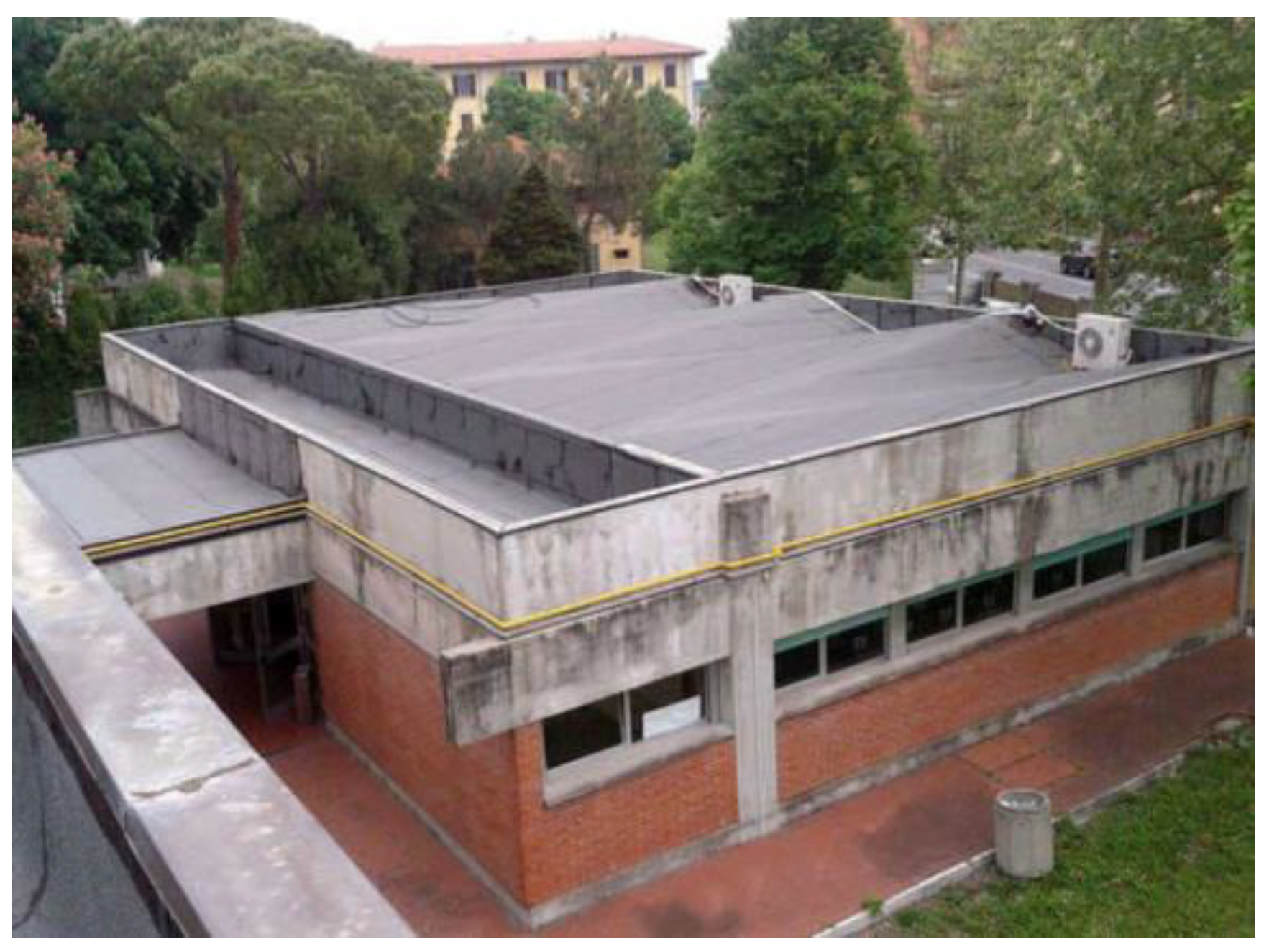
14] to determine the potentials and limits of the historical building, carrying out precise investigations regarding the whole enclosure and more specifically the stratigraphy of the external cladding in its opaque and windowed parts and of the roofing. This will be necessary for GW and LW in order to evaluate the most suitable fastening systems to masonry and for the GR to determine, in addition to the new overloads, also the sealing layers to avoid subsequent infiltrations. The wall of the case study examined, being a homogeneous masonry in blocks of concrete for its entire development, did not show difficulties in implementing the metal structure, supporting the LW, consisting of aluminum brackets and supports for the vertical T and L aluminum profiles, which allow quick and easy installation of the components and which are fastened to the external wall behind by stainless steel anchors. However, in the case of historical, uneven walls, in which the wall texture is made up of several materials, there is the need to use vertical support profiles with fastenings at relatively large distances so that unwanted drilling of the walls is not required. The slab of the case study, from the comparison with similar structures around the same period, was supposed to be a concrete and masonry roofing system and from the reliefs it was found, in its flat part, to be 25 cm thick; the visual analysis allowed us to find the presence of a 1 cm-thick bituminous sheath and a concrete screed for slopes with an average thickness of 3 cm, in the sloping pitched part, with a variable inclination from 19° to 5°, a thickness of 20 cm and the same sheath. After the considerations concerning the enclosure, we evaluated the relative physical characteristics of the materials, the thermal transmittance of the perimeter walls and the roof slab, the age of the building components, the presence or absence of interstitial condensation, and the type and effectiveness of insulation.
In complex projects it is necessary to consider how the presence of GSI reduces summer irradiation, especially in Mediterranean climates [
15,
16,
17,
18] and the relative reduction of problems related to the overheating of the building and the control and minimization of thermal stratifications; all of this must always be related to the possible presence of the decorative apparatus which must not be ignored (
Figure 3).
For the roofing system, we will consider in addition to its geometry, in pitched inclination terms, the materials that compose it, the type of insulation used to verify the transmittance, and the relative dispersion to the outside; from this part of the feasibility, the GR will result; it can also be integrated into photovoltaic and solar thermal systems.
As regards the containment structures, in order to install GW or LW, we must consider the windowed walls and analyze the types of windows (wood, aluminum, PVC, etc.) and glass (simple, double, etc.); not surprisingly, the presence of irrigation systems and of the vegetal mass, entails the need to put in place special tinsmithing for the protection of the opening intrados (
Figure 4).
Each material used corresponds to a given transmittance coefficient from which it is possible to determine the corresponding thermal dispersions. Further direct investigations on the oldness ratio of the materials will allow us to determine their energy efficiency and a thermal bridge mapping will be performed [
19,
20].
These examinations allow the writing of a report that identifies the critical issues of the building with its relative weaker parts from the point of view of energy containment, in addition to the precise assessment of its overall energy efficiency.
3.2. Analysis of the Structural Components of the Building
Further direct investigations on the oldness ratio of the the national legislation in force NTC 2018 [
21] establishes the general criteria for the assessment of safety and for the design, execution, and testing of interventions on existing buildings. Specifically, we introduce the general criteria with which it is possible to define the state of conservation of different types of buildings and to distinguish accordingly the types of intervention that can be performed. In confirmation of the previous paragraphs, the legislation [
22] highlights the importance of conducting specific analyses and surveys to reach an in-depth knowledge of the actual state of the work, in particular:
if the construction reflects the state of technical knowledge at the period of its construction;
if there may be unassessed defects in setting and implementation;
if the current structures differ from the original ones due to degradation and substantial changes;
if the building subjected to actions, even exceptional ones, whose effects are not completely evident.
This level of knowledge makes it possible to determine the various structural geometries and constructive elements, the permanent agent loads, and the mechanical properties of the materials in order to apply the use of structural calculation models for the static verification of the intervention.
3.3. Analysis of the Components of the GR
As reported in the specific regulation [
23], the primary items involved in a GR concern vegetation crops, separation or filtering draining water storage systems, protection against root drops, watertight sealing, thermal insulation, acoustic insulation, and load-bearing elements. The secondary elements could be: ventilation, the vapor barrier layer, the slope layer and the regularization layer, and the load distribution layer. The accessory elements of a GR are the irrigation layer or system, those for keeping in place the culture layer; those for securing the draining element; anchorage of vegetation; the fire barrier; the inspection little wells and any antifall systems (
Figure 5,
Figure 6 and
Figure 7).
3.4. Analysis of the Components of The GW and LW
Two technical alternatives can be implemented depending on whether the plants are able to support themselves or if they need special supports to lean on (
Figure 8). In the first case it is necessary to pay attention to the surfaces to which this natural coating is to be applied, since they could damage the anchorages of the plants or the plants could damage the external surface of the building. The second case applies to plant species that do not have anchoring organs and which need support structures chosen in relation to how they cling to the support; the latter must be resistant to stress and last for a long time; in both cases the plant, a creeper, has its roots on the ground and grows along the facade. Then there is the solution with containers, placed at a certain height, for the lodging of the plants which grow again spreading along the façade, though on special supports.
Systems with modular panels can be classified according to whether they are composed of a groundless textile substrate or are made up of modular cell systems with a substrate made of soil or expanded material. These systems, in which plants grow and are nourished through hydroponic techniques entail a very light weight; however, attention must be paid to the continuous irrigation percolation that could affect the structures behind. For this reason, coating works with low-thickness sheets of the intrados of the openings are also necessary to protect the windows, so that the facade phonometries are not reduced (
Figure 9).
It is to be observed that maintenance interventions, more complex than those of the GR (given the ground-roof development and often the difficulty of achieving it), involve: plants, with irrigation interventions, fertilization, development guide, fastening to supports and pruning; the brackets to the support structures, with the control of the stability of the whole structure, the control of the correct position and the closeness to the wall, and the control of the physical-chemical stability of the materials; the enveloping walls, with the control of the mechanical integrity and the chemical stability of the walls.
4. Results
Considering the installation of the GR above the roof of an existing building, as a retrofit technique, it is necessary to define the working loads in order to carry out a future structural calculation for each specific case study. It will be necessary, indeed, to verify that the structure be able to support the additional strain and to respect the safety required by the legislation [
13]. In relation to the experiments carried out, both in the case study of the LW and the GR, it results that the choice must be directed towards a type of intervention that does not seriously affect the existing structure and maintains the present load conditions, both of the wall and of the coverage almost unchanged.
In regards to green roofs, light interventions are appropriate, their load being almost exclusively represented by the presence of water in the substrate and in the accumulation and drainage layer. The corresponding GR is the extensive type because it is characterized by reduced thicknesses, the one examined is 16 cm (22 cm including the insulation panel), and is low-weight also thanks to the use of Sedum for the vegetational part: 127 kg/m2 at maximum saturation and 75 kg/m2 at dry conditions, when the water content of the GR, using rainfall data of the area together with the storage and drainage capacity of the panel considered, is equal to 52,16 mm/m2 (kg/m2).
These data, when compared with an analysis of the loads of an existing roof consisting of only one layer of slate, usually used in roofs where you cannot walk, show how the removal of the latter (with a weight of about 120 kg/m2), and with the removal of any slope screed (with a weight of about 80 kg/m2) could also allow the subsequent laying of the GR considered keeping the load conditions almost unchanged.
The objective of the present study is to highlight the architectural works necessary for the laying of a GR on an existing building, and those emerging in the simulation conducted, that led to the energy and economic assessments not presented here, suggesting a series of technical solutions such as:
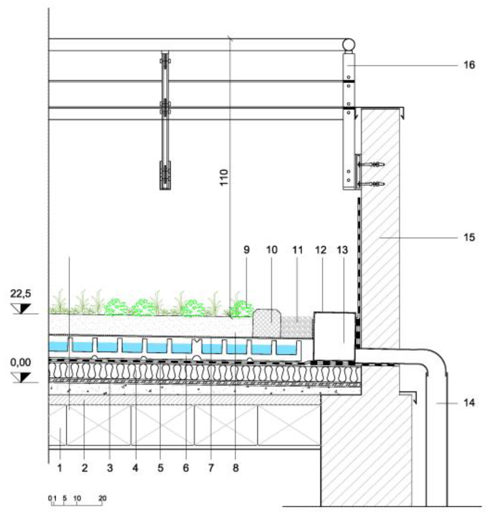
In the interventions on existing roofs, as shown also in the case study, it is necessary to raise the perimeter edges of the roof, to contain the greater thickness of the stratigraphy, due to the laying of the constructive elements of the GR. Interventions that affect the eaves, ledges, ribs—as in the case studied—become even more complex when we have to work on buildings of a certain historical value, owing to the original construction techniques, think of the delicacy of wooden roofing, and owing to the large decorative apparatus that finds one of the highest expressions in the gutters with finely worked ledges. The simulation, in the case study, provided for a cant of the ribs through the mechanical connection of structures, along the perimeter of the existing structure, to which the new roof flashings can be hooked; they can also be integrated with the existing ledges, all of this can be done keeping in mind the building legislation on the prevention of the risk of falls from a high building. An intervention that can also be extended to flat roofs to make the total height of the building uniform and also to guarantee stability and security requirements.
The accumulation of rainwater and irrigation, in the cases of both inclined and flat roofing, must consider the proper sizing of the existing downspouts which, if necessary, must be integrated with new ones by intervening on the existing structures, for example on the covering ribs of the case study, creating holes that allow the connection of the covering to the downspouts arranged along the perimeter of the building; in addition to that, in order to allow accessibility and maintenance of the drains, some control wells should be positioned.
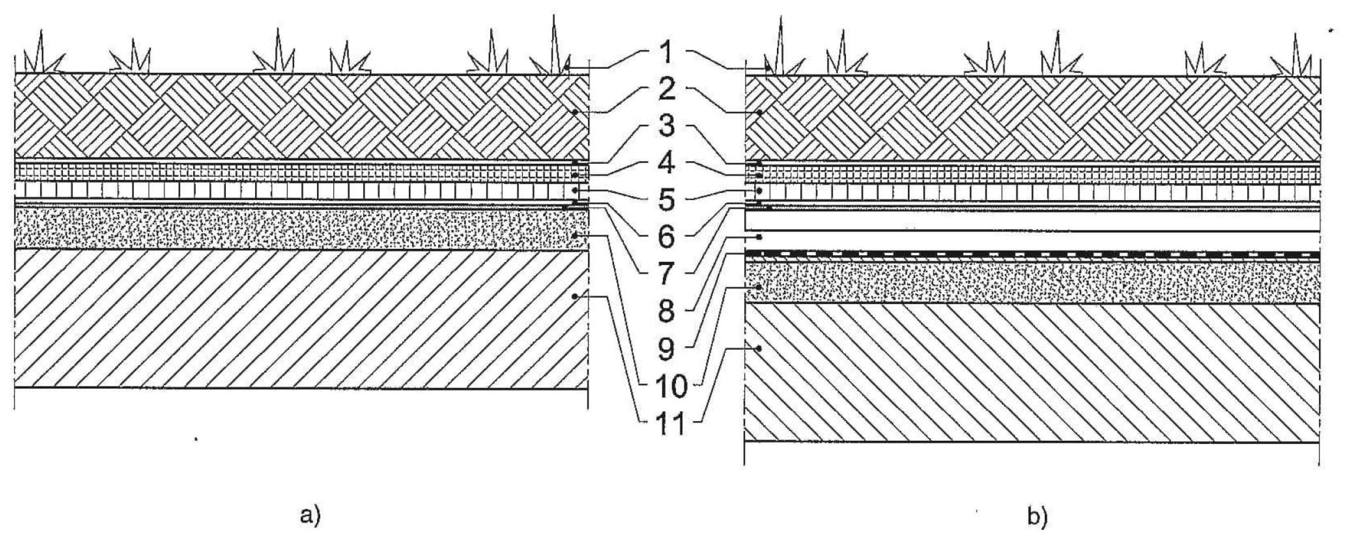
To realize the horizontal extensive GR of the case study (
Figure 10 and
Figure 11), the following are applied on the slab: vapor barrier, insulating panel, waterproof and anti-root sheath, modular draining element for the lodging of the plants, filtering cloth, substrate for the plants, and Sedum plant layer owing to its lower weight and low maintenance.
In regards to the tilted extensive GR, the case study highlighted the problems that might occur in similar situations when it is necessary to apply it because of precise architectural requirements or environmental reasons (
Figure 12 and
Figure 13). There is a complexity demonstrated by the added need to give stability and security to the entire sloping system, also allowing the regular disposal of water. Therefore, the roofing requires a very careful design that evaluates in depth the characteristics of the retention systems and of their bracketing—the system considered provides for the use of special plugs that remain retractable within the thickness of the entire package, fastened to the existing underlying structure and waterproofed; a system that still requires improvement in terms of watertightness—and all the particularities of functioning related to the geometry of the pitch and its slope, the drainage of the water, and the type of vegetation. As the inclination increases, there is a consequent increase of maintenance costs, because at the base of the pitch it is suitable to increase the drainage capacity to allow a rapid flow of the water accumulated to the drains. The maintenance of the extensive GRs is divided mainly into three phases: the completion care (up to a coverage ratio of 80% [
18] with a duration of approximately 12 to 15 months), regular start-up maintenance (follows the completion and concerns maintenance until the functional state is reached—duration from 2 to 4 years), ordinary maintenance (regarding the maintenance of vegetation—duration dependent on the maintenance contract).
According to the necessity and intensity and development of the planting, the maintenance interventions involve: irrigation (priority in the initial phase), weeding the application of slow-release organic or inorganic fertilizer, the reseeding or plant reimplantation, substrate thickness control, cleaning of covering edges, drainage channels, and inspection of little wells and drains.
Considering vertical systems, the problems concerning the installation of GW and GL on the facades are related to the kind of facade, even ventilated claddings, fixed to the building structure. Specifically, the problems to be verified and resolved are:
Geometry and inclination of structure and coating
Alignments and holes for windows and doors
Interconnection of doors and windows with the intrados and facade
Acoustic bridges
Thermal bridges
Type and connection system and internal-external coordination
Collection and disposal of rainwater
Assembly and disassembly flexibility
Interface with other subsystems, plants, elements
Cleaning of facades and glazed components
Maintenance of cladding and windows
Of particular importance for a correct design of the GW and LW are the calculation of the dimensions of the fixings: vegetated-substructure system and substructure-wall building.
The case study showed a simple assemblage due to the presence of an external wall with regular texture (
Figure 14,
Figure 15,
Figure 16,
Figure 17 and
Figure 18). However, in cases of intervention on historical structures, where there is uncertainty about the construction techniques or the possible plant components inside the partitions that may affect the insertion of fixing systems, a first assessment of the state of the construction could be appropriate through the use of tools that reveal the existing wall texture.
The dimensions of the metal substructures, of the support and brackets of the elements conforming the plants, and of the other components of the anchoring system must be calculated according to:
vertical load, with particular reference to the bending moment and to the different states of humidity of the system in case of LW;
horizontal thrusts, that is the forces of compression and depression of the wind, with reference to the GW, because they consist of climbing green on racks or cables placed on the facade that could tear, and to the LW whose panels could become loose.
To assess the dimensioning of the whole system, it is therefore necessary to calculate the wind pressure and depression, determinate the exposure coefficient that depends on the height of the construction on the ground, the roughness classes, the thermal variations, to calculate the air blade with its compartmentalization in cases of LW. The latter is recommended to be implemented, to optimize the LW yield, with a compartmentalization of the ventilation layer, using, if possible, the profiles of the substructure of the bracketing system, otherwise inserting appropriate flashings. This compartmentalization, first of all, creates a physical barrier to the spread of flames or combustion products resulting from a possible fire and makes the LW an advanced technological system comparable to ventilated facades.
5. Conclusions and Future Developments
The extensive scientific literature on greenery systems integrated into the building envelope GSI [
23], whether GR or GW and LW, illustrates their benefits under various aspects, from energy saving and acoustical to ecological and psychological aspects [
24,
25,
26,
27], on experimental models, laboratory tests and realizations, very often verifying only the performances of the stratigraphic sections that make up the systems. However, the problems related to retrofitting interventions are still uncertain because the application of GSI also involves other technological works that sometimes go beyond the systems themselves but which are necessary for their correct installation in relation to existing structures.
With this in mind, and from the results of the analysis carried out and the solutions verified, this study tries to highlight the series of design procedures necessary both in the preliminary phase and then in the executive phase, to relate the GSI to the existing building envelopes, focusing on the works necessary so that these can be implemented in existing buildings. The GR, from the results of the simulations conducted, demonstrate a greater simplicity in their construction, with improvements also from the point of view of the working loads on the existing structures, since the interventions are performed more easily than those on the facade. It is to be considered, indeed, that the openings on the roofs are normally fewer in number than in a facade with all the positive consequences for possible insulation and connection works. The study, however, highlights the architectural needs that are not always considered such as the increase in the thickness of the roof and the related need to raise its edges, changing the perspective of the building (
Table 2).
On the other hand, the GW and the LW, the latter analysed in its application on a newly-constructed existing brick wall, show some complexity in their construction because they must deal with facades often rich in decorative elements and where openings affect the assemblage and connection works such as the tinsmiths of the intrados of the openings. The necessity of having to drill masonry, often inhomogeneous, to connect fixings and the problems of stability this entails, must be carefully analyzed. The energy and environmental advantages, widely analyzed by the studies in progress, are a counterweight to these seeming difficulties that can easily be overcome with the optimization of models of assisted design (B.I.M., H.B.I.M., advanced survey methods) (
Table 3).
The intervention criteria and the guidelines, here exposed, for the application of the GSI to the Italian context (materials and construction techniques), also in relation to the context, could be the beginning for the next step of research, for a quantitative verification in relation to other possible solutions. However, the scenarios are nevertheless open to experimenting with increasingly technologically flexible GSI solutions, so that they may become a valid tool available to the existing building heritage.

 ,
, 


