Abstract
The paper presents an innovative lightweight design solution for the rear crash management system of a C-class car, developed within the AffordabLe LIghtweight Automobiles AlliaNCE (ALLIANCE) EU research project. The innovation provides that the reference version of the module, based on conventional steel components, is revolutionized through the introduction of extruded 6000/7000 series aluminum alloys. The two competing alternatives are described and compared in relation to design and technological solutions, including also a sustainability analysis which assesses the entire Life Cycle (LC) of the system on the basis of a wide range of environmental indicators. The lightweight solution allows achieving a large mass reduction (almost 40%), while providing improvements in terms of strength, production efficiency and design freedom. On the other hand, the introduction of new materials and manufacturing technologies entails contrasting sustainability effects depending on impact category, thus not allowing to affirm that the novel alternative is unequivocally preferable under the environmental point of view. However, the comprehensive evaluation of all sustainability aspects through a multi-criteria decision analysis (TOPSIS method) reveals that the environmental profile of the innovative design is slightly preferable with respect to the conventional one.
1. Introduction
One of the main objectives of the European community policies is the mitigation of Greenhouse Gas (GHG) emissions by 60% compared to the 1990 levels by 2050 [1]. To achieve this ambitious objective, several legal community restrictions have been established in recent years, such as the GHG emission targets according to the European Union (EU) directive 443/2009 [2]. On this aspect, a decisive contribution is expected from road transportation, since this sector is responsible for about 20% of total CO2 emissions within the European area [3]. Despite the encouraging results of certain measures already taken at the EU level, substantial further progresses are needed both in research and technological industry development.
To date, a widespread approach to meet the described requirements is the application of lightweight design, especially for body vehicle parts. Automotive lightweighting is in the forefront of research and industry development activities for several reasons. First of all, weight reduction provides improvement in terms of vehicle technical features and performances, such as higher speed and acceleration [4,5]. At the same time, lower mass means best stability and handling as well as shorter braking distance, thus providing a substantial contribution to meet the continuously rising legal safety requirements [6,7]. Last, but not least, weight reduction has an important role in both lowering the Fuel Consumption (FC) and the associated exhaust gas emissions which involve positive effects under a series of different perspectives: material and energy resources protection, cheap, clean and convenient fuel supply chain, as well as reduction of environmental impacts in compliance with the very strict and rigorous legal restrictions [8,9]. Lightweighting is a design strategy aimed at improving the load-bearing capacity of car components in order to decrease the overall vehicle mass without downgrading (or even increasing) its performances or compromising any of the components’ functions. The approach is based on a combination of different scientific disciplines (such as advanced mechanics, material science, product and process development) which are interrelated through the application of higher computer-aided engineering modelling methods.
Historically, mild cold rolled steel has been a very popular construction material adopted for car body structure, as the sheet metal forming is the most important manufacturing process [10]. However, in the last two decades, the need for mass reduction had launched a series of dynamic and multidirectional developments [11,12]. In particular, the recent periods have witnessed the diffusion of several lightweight composite materials which are increasingly being used in the most disparate applications such as Body-In-White (BIW), outer skin components and wheel rims [13]. These are mainly Carbon or Glass Fiber Reinforced Plastics (CFRPs, GFRPs) where the most common matrices are thermoset resins (such as polyester or epoxy) and thermoplastic polymers (such as polyamide or polypropylene) [14]. Composites are also widely used in combination with metals to form hybrid, multi-material and sandwich structures through the adoption of joining technologies (such as adhesive bonding [15], rivets [16] or new forms of mechanical joining [17]) to combine different materials on a part level. These types of solutions offer a great potential of mass decrease which, in turn, lead to significant improvements in terms of vehicle performance, safety and cost. On the other hand, the introduction of composite and hybrid materials has contrasting effects when considering the environmental aspects [18]. Indeed, despite the undeniable benefit in the use stage due to lower FC and exhaust air emissions, CFRPs and GFRPs show serious environmental hotspots in raw material provision and manufacturing [19]. This is mainly caused by a significantly larger demand for energy and resources in the respective stages when compared to metal alternatives [20]. Additionally, the combination of different materials and the variety of joints applied give considerable problems in the separation and recycling at End-of-Life (EoL) [21,22]. In fact, existing disassembly and recycling technologies do not allow achieving satisfactory recovery rates as well as acceptable quality of the recycled fraction [16]. As a consequence, use phase energy savings through weight reduction may only partially compensate these added impacts, often resulting in higher environmental burdens when considering the entire LC (Life Cycle) of the components [23]. With respect to manufacturing processes, Additive Manufacturing (AM) constitutes a great innovation for automotive design, with lattice structures representing the main field of application of such a technology [24]. The ability to locally print complex shapes and geometries offers great potentiality in terms of weight reduction and design freedom with respect to conventional processes (i.e., high-speed machining), along with reduced tool wear and lower surface quality deterioration [25]. Additionally, AM enables to decrease production time while guaranteeing rapid prototyping and highly decentralized production. Another advantage is the reduction in material waste and fuel/energy consumption, which translates into resource-saving and lower environmental impacts [26]. That said, the environmental profile of AM technology strongly depends on the specific case study and it needs to be extensively examined through future studies that increase the current knowledge level [27]. Against the benefits cited above, the main drawbacks of AM are constituted by limitation in the size of components, reduced range of materials, and high cost of production, machinery and tooling. In addition to the development of novel composites and hybrid materials, nowadays, automotive lightweighting is also re-discovering advanced designs based on metals. This includes innovative high-strength steel and 6000/7000 aluminum series alloys [10,28], new topologies, as well as adapted manufacturing processes [10,29]. The combination of novel materials with different manufacturing technologies enables to reduce the thickness of car structural components without compromising the structural integrity, thus achieving a wide spectrum of mechanical properties with respect to the intended applications [30,31]. In general, average mass reductions of about 10–30% are provided through high-strength and advanced high-strength steels. Some examples of lightweight steel design are represented by the replacement of frame constructions with shell designs made by stamping and welding or the introduction of tailor-rolled blanks [32]. On the other hand, aluminum shows even higher lightweight potentials with respect to steel, thanks to the considerably lower specific mass. Indeed, the comparatively lesser strength is compensated by thicker structural parts without significantly increasing vehicle mass. A very promising application of aluminum lightweight design is the construction of car spaceframe structures through extruded sections [33]. Concerning the environment, high-strength metals show an eco-profile which is qualitatively similar with respect to composites and hybrid materials: greater specific impacts (per kg of material used) upstream to the operation phase if compared to low-alloyed steels [34,35] and, on the other hand, lower FC and greenhouse gas emissions during use [36]. The difference lies in the fact that the drawback in production is usually not so high for advanced metals, so that FC saving during use is able to offset the negative effects at relatively low life cycle distances (less than 100,000 km) [37,38]; on the contrary, the relevant impact increase in raw material provision for composites and hybrid materials makes that the environmental benefits during operation are not enough to achieve a break-even point within the assumed LC mileage [39]. In this regard, a crucial point is represented by the share of secondary sources used for material provision, on the basis of which the system-level payback times can shorten or extend significantly [40]. High-strength metals allow achieving environmental benefits also at EoL, especially if compared to composites. Indeed, currently available technologies enable high separability and recyclability rates for steel and aluminum, which mean lower demand for primary raw materials [41,42,43]. Anyway, the required quantity of material with respect to functional requirements and mass reduction obtained need to be evaluated separately for each case study, since they are both decisive in order to quantify the impacts in raw material acquisition and EoL stages, but represent, as well, critical elements for assessing the abatement of environmental burdens during operation.
This paper presents a re-engineering activity performed on the rear Crash Management System (CMS) module of a C-class car and it is a follow-up of [44]. Starting from the reference steel-based CMS module, a lightweight variant made of ultra-high-strength aluminum extrusions is obtained which provides significant weight reduction while maintaining performance, safety and functionality level. The novel solution is assessed and compared to the baseline in terms of lightweight potential as well as design and sustainability improvement. The implications of lightweighting are critically discussed through an assessment approach based on several environmental aspects, which allows interpreting potential opposite effects as well as combining results in order to define the optimal solution. The design and research activity has been carried out within the AffordabLe LIghtweight Automobiles AlliaNCE (ALLIANCE) European research and innovation project [45], whose objective is developing innovative advanced materials and manufacturing technologies to reach 25% full-vehicle weight reduction while decreasing the global warming impact by 6%.
2. Materials and Methods
2.1. Module Design
Table 1 provides an overview of the main design features for both baseline and lightweight CMS versions: data are reported for each component including material, thickness and manufacturing process as well as an image of the overall module. The reference vehicle for the CMS use phase is a gasoline C-class car.

Table 1.
Overview of design solutions for the CMS (Crash Management System) module.
The baseline design version is made of cold stamped steel with a mass of about 4 kg and it is composed of four main component typologies: beam, crash box, backplate and towing system. Steel grades are selected based on achieving optimal performance whilst staying in the economically favorable cold stamping material range. The lightweight CMS is designed to meet the performance of the baseline version with regard to two criteria:
- -
- maximum deformation and energy absorption during RCAR low-speed structural crash test protocol for rear impact [46] and
- -
- bending moment when applying a deformation in the center of the beam.
Further imposed requirements (valid for both design alternatives) are that no breakage occurs at 105 mm intrusion in the mentioned bending load case as well as meeting OEM strength and durability requirement for the towing attachment. The innovative solution is composed by the same parts of the baseline and, since its footprint is very similar to the one of the reference CMS, it does not require any modification of the surrounding components. The base material for the lightweight module design is ultra-high-strength aluminum alloy with a total mass of about 2.4 kg. The newly developed beam component consists of an open beam extruded profile made of the precipitation hardenable high-strength aluminum alloy 7003, with a thickness which ranges from 1.8 to 2.0 mm. The open extruded profile design combined with a special forming concept offers the best compromise between weight savings, costs and robustness against crash. Crash box and backplate are also aluminum alloy 7003 extruded parts, with a thickness respectively of 2.1 and 4.0 mm. A very ductile high-strength version of the alloy AW7003 in a slightly overaged temper (T7) is used for the crash boxes, due to the very high ductility requirements of these components. Even though 6000 alloys allow to achieve the same adjusted strength of AW7003, this alloy provides increased performances in terms of resistance to crack initiation, deformability and stability of mechanical properties in large-volume production, thus combining high-strength level with good ductility behavior and high production efficiency. For the beam profile, the chosen alloy is trimmed to a slightly higher strength as for the other two components. Beam, crash box and backplate components provide satisfactory properties in terms of mass reduction, strength, production efficiency and design freedom thanks to the choice of a very ductile aluminum extrusion alloy. The towing system is made of the aluminum alloy 6082, a precipitation hardenable high-strength alloy of the 6000 series. Overall, design choices implemented in the lightweight design (material change, application of heat treatment and use of tailored extruded blanks) allow achieving a weight reduction of nearly 40% with respect to the reference CMS version while maintaining the same performance, safety and functionality requirements.
2.2. Sustainability Assessment
The objective of this section is comparing from an environmental point of view the baseline and lightweight design solutions for the CMS module. The sustainability assessment is performed through the Life Cycle Assessment (LCA) methodology [47], which allows to evaluate the environmental impacts associated with a product, process or service according to the environmental management standards ISO 14,040 [48].
2.2.1. System Boundaries and Impact Categories
The analysis takes into account the entire LC of the module subdivided into production, use and EoL stages, and it is carried out considering the following impact categories assessed through the ILCD Life Cycle Impact Assessment (LCIA) method [47]:
- -
- Acidification midpoint (A) [Mole of H + Equation];
- -
- Climate Change midpoint (CC) [kg CO2 Equation];
- -
- Ozone Depletion midpoint (OD) [kg CFC-11 Equation];
- -
- Particulate Matter/Respiratory inorganics midpoint (PM) [kg PM2.5 Equation];
- -
- Photochemical Ozone Formation midpoint, human health (POF) [kg NMVOC Equation];
- -
- Resource Depletion, mineral, fossils and renewables, midpoint (RD) [kg Sb Equation].
2.2.2. Functional Unit
The Functional Unit (FU) is defined as the CMS module installed on the reference vehicle with a LC mileage of 230,000 km [49], and assuming that reference and innovative design options provide unaltered mechanical and functional performances. The assessment of FC and exhaust air emissions during operation is based on the Worldwide Harmonized Light-Duty Test Procedure (WLTP) [50].
2.2.3. Life Cycle Inventory (LCI)
Data collection is performed for each one of the three main LC phases in terms of materials/energy consumption, waste production and emissions to the environment which are modelled through LCI processes and elementary flows from the GaBi dataset [51].
Concerning production, the inventory is carried out separately for raw material acquisition (which takes into account the entire production chain of materials, from primary material extraction up to the production of semi-finished products) and manufacturing (which incorporates activities for converting semi-finished products into the final module components) sub-phases. For both materials and manufacturing steps, the inventory is performed through the break-down approach [35] which has been already applied in ENLIGHT [52] and e-LCAr [53] projects. Such an approach provides that each mono-material component of the CMS system is assessed separately and the overall impact of the production stage is determined by summing up contributions of the single mono-material parts. Data collection regarding raw material acquisition is mainly constituted by secondary data (both from scientific literature and GaBi dataset) on the basis of CMS material composition and manufacturing processes (Table 1). Manufacturing sub-stage takes into account energy consumption and material losses involved by production processes of finished parts. The assessment includes also the recycling of metal scrap produced by manufacturing activities: materials are assumed to be recycled through an open loop recycling which provides environmental credits due to the substitution of primary resources with recycled materials. Recycling is assessed as the sum of environmental impacts (material/energy consumption and emissions of recycling activities) and credits (avoided burdens), and the inventory is modelled as an avoided production of primary material through specific substitution factors from the GaBi LCI database [51]. Joining, assembly and transportations during production are out of the system boundaries since a pre-assessment investigation shows that their impact is negligible with respect to the considered impact categories. Unlike material provision, the inventory data collection for the manufacturing phase is based on primary data coming from direct measurements on suppliers and Original Equipment Manufacturer (OEM) process sites.
The use stage assesses impacts associated with module operation, which are determined by two contributions: fuel production chain upstream to useful life (the so-called Well-To-Tank, WTT) and exhaust air emissions during driving (the so-called Tank-To-Wheel, TTW). The required data for the use stage modelling is the amount of FC and CO2/SO2 emissions associated with CMS operation. The inventory of both WTT and TTW steps is based on secondary data from the LCI GaBi dataset. More specifically, the determination of FC and exhaust air emissions associated with the CMS module is carried out through the FRV-based approach [54] whose analytical background, underlying assumptions and boundary conditions are reported below and in Table 2.
where:
Table 2.
LCI (Life Cycle Impact) data collection.
CO2 comp = amount of CO2 emissions associated with component operation (g)
CO2 km = vehicle CO2 emissions per kilometer (g/km)
mileageuse = use stage mileage (km)
FCcomp = amount of Fuel Consumption associated with component operation (kg)
FCveh = total LC vehicle Fuel Consumption (kg)
SO2 comp = amount of SO2 emissions associated with component operation (kg)
SO2 km = vehicle SO2 emissions per kilometer (kg/km)
FC100km = vehicle Fuel Consumption per 100 km (L/100 km)
2370 = mass of CO2 emissions per liter of petrol (g/L)
ρfuel = fuel density [kg/L]
FRV = Fuel Reduction Value (L/100 km*100 kg) [54]
mcomp = component mass (kg)
ppmsulphur = sulphur content in fuel (ppm)
The inventory of EoL stage is modelled according to the 2000/53/EC Directive [55]. The considered EoL scenarios for steel and aluminum components are consistent with ISO standard 22628:2002 [56], and they are defined on the basis of the current European technology level. Since the CMS is not a system that is usually disassembled for reuse/recovery purposes (low mass and positioning within the car not favorable with respect to removal), it is assumed that it remains on the EoL vehicle and it is forwarded to the shredding process. After that, the scenario provides material separation and open loop recycling. Recycling is assessed as the sum of environmental impacts (material/energy consumption and emissions of recycling activities) and credits due to the substitution of primary resources with recycled materials (modelled through specific substitution factors from the Gabi LCI database). Table 2 shows LCI data for shredding, sorting and recycling processes.
3. Results and Discussion
Table 3 reports the LCIA results for reference and lightweight design solutions for each one of the LC stages.
Table 3.
LCIA (Life Cycle Impact Assessment) results for reference and lightweight design solutions.
Discussion in terms of impact allocation between LC stages/module components as well as impact variation involved by lightweight design is reported in the following paragraphs.
3.1. Contribution Analysis of Impacts: Influence of LC Stages and Module Components
Figure 1 reports the contribution analysis of impact by LC stage and module component for the reference CMS design. The first point is that the very large majority of environmental burdens (more than 98% for all impact categories) is associated with production and use. Operation is definitely the most significant stage for A, CC and POF categories, for which it covers, respectively, around 60, 82 and 61% of total LC absolute impact. Looking at use sub-phases, TTW is predominant for CC (almost 80% of total use stage), while for all the other categories, the near totality (more than 98%) of operation burden is associated with WTT (Figure 2). On the other hand, production involves almost the entire LC impact for OD and RD categories (respectively, about 99 and 97%), while for PM, the quota of production results is similar to the one of use (around 50%). In this regard, it is worthy to mention that the production impact is largely associated with materials’ sub-stage, since the contribution of manufacturing is lower than 4% of total production for all indicators (see Table 3). Concerning EoL, material recycling involves environmental credits for the entire set of categories with the exception of OD, for which the impact is positive. However, the percent share associated with EoL is very small, less than 2% for all indicators. The reason for this is the low substitution factor (in terms of avoided production of primary materials) of steel recycling, which is primarily due to two reasons: on one hand, the high energy demand of steel re-melting processes and on the other hand, the need for primary alloy elements that have to be added to the EoL steel in order to achieve the same quality of primary material.
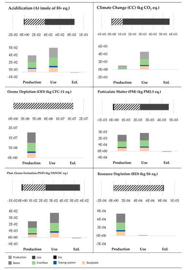
Figure 1.
Contribution analysis of impact by LC (Life Cycle) stage and module component—Reference CMS design.
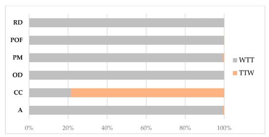
Figure 2.
Contribution analysis of use stage impact by TTW (Tank-To-Wheel) and WTT (Well-To-Tank) (both reference and lightweight CMS design).
Considering the LCI elementary flows which mostly contribute to the environmental burdens, sulphur dioxide emissions (more or less equally distributed between materials and WTT phases) play a key role for A and PM, for which they cover, respectively, around 65 and 56% of the overall LC impact; for PM, another influential emission flow is PM2.5, whose share is 35%. About 95% of total LC CC is caused by carbon dioxide emissions which mainly occur during module operation, while 99% of OD is associated with halogenated emissions to air (trichlorofluoromethane, dichlorotetrafluoroethane and dichlorodifluoromethane). Finally, POF and RD categories show a more varied composition. For POF, most of the impact is distributed between nitrogen oxides/dioxides (mainly from materials and use stage, and representing about 58% of total LC amount) and Non-Methane Volatile Organic Compounds Emissions (NMVOC) (mainly from use stage and representing about 23% of total LC amount). For RD, the higher quotas are associated with lead (53%), silver (21%) and zinc (20%), almost exclusively concentrated within production. The contribution analysis by module component (Figure 1) stresses that the allocation of impact is more or less similar for all the considered categories. The explanation for this is that both base material and manufacturing process are the same (steel and cold stamping—Table 1) for all the CMS module parts, and therefore, the distribution of impacts directly reflects the mass of the components. The small differences are primarily ascribable to variations in manufacturing energy consumption and scrap rate that occur passing from one part to the other. As a consequence, the highest quotas are associated with beam and crash box components (around 65–75%), with lesser contributions from backplate and towing system (about 25–35%).
Concerning the lightweight design, the allocation of impact between LC stages provides clearly different outcomes with respect to the reference CMS module (Figure 3). First of all, the significance of use stage is notably reduced. Operation is the most influential phase only for CC (about 47% of total absolute impact) while the share does not exceed 2% for the other environmental indicators; the allocation between TTW and WTT use sub-phases remains unaltered with respect to the reference CMS design (Figure 2). The decreased relevance of use stage is due to the lower mass of the module which means reduction both in fuel demand and exhaust air emissions during operation. On the opposite, the relevance of production stage strongly grows, since it appears to be the major contributor for five of six impact categories (for which it ranges between 55 and 96% of total LC impact depending on indicator): this is primarily ascribable to the higher energy intensity of raw material provision of aluminum in comparison to steel. Once again, the influence of manufacturing is low if compared to material acquisition, less than 5% of total production impact for all indicators with the exception of OD for which it is around 16%. The other major variation with respect to the reference design is the increased relevance of EoL, whose quota varies from 5% up to 23% of total LC amount. In particular, for OD, the lightweight CMS design provides a credit at EoL, against a positive impact of the reference version.
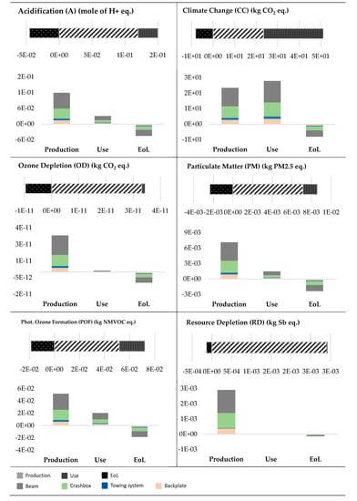
Figure 3.
Contribution analysis of impact by LC stage and module component—Lightweight CMS design.
The analysis of LCI elementary flows for A, CC, PM and POF shows analogous results with respect to the steel CMS, both in terms of typology of emissions and relative contribution to the overall LC impact. On the other hand, OD is almost completely ascribable to chlorodifluoromethane emissions (that cover about 98% of total LC OD and occur to the same extent in all LC stages), while RD is mainly caused by calcium fluoride, bauxite and silver depletion (for which the contribution to the overall impact is respectively 32, 22 and 18% and whose consumption is located primarily in raw material acquisition). Similar to the reference design, the contribution analysis by module component remains more or less similar passing from one impact category to the other. Once again, the explanation is that the base construction material is the same (high-strength aluminum alloy) for all the CMS parts (even if differences occur in manufacturing processes), which entails that impact allocation is mainly determined by component mass. Beam and crash box provide the highest contributions (around 70–80%), while significance of backplate and towing system is significantly lower (about 20–30%). The only exception to this rule is represented by RD, for which the contribution of towing system component is notably lower with respect to the other indicators (less than 1%).
3.2. Comparative Assessment Reference—Lightweight Design
Figure 4 shows the impact variation involved by the lightweight design for the considered LCIA categories: data are reported in absolute and percentage terms for both different LC stages and total LC.
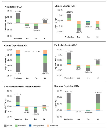
Figure 4.
Impact variation involved by lightweight design.
Concerning production, all indicators with the exception of OD have a decisive increase, which ranges from 125% for CC up to 260% for RD. This effect can be explained through the higher energy intensity of raw material provision of aluminum which is not compensated by the reduction of materials used (about 39% mass saving). As a consequence, the mass-specific impact of production (impact per kg of finished component) results notably higher for the lightweight alternative with respect to the reference one. The investigation of LCI elementary flows reveals that the impact growth is mainly ascribable to the increase in sulphur dioxide (255%), carbon dioxide (10 %), PM2.5 (254%), nitrogen oxides/dioxides (199%) emission and silver consumption (600%), respectively for A, CC, PM, POF and RD categories. On the other hand, OD shows a drastic reduction in the production impact (−99.99%): this is almost exclusively associated with the massive drop in trichlorofluoromethane and dichlorotetrafluoroethane emissions in raw material extraction and production processes passing from aluminum to steel. The variation in production impacts is mainly associated with the components of beam and crash box, due to the higher mass reduction achieved by lightweight design for these parts. On the other hand, since the novel solution involves a substitution of steel with 6000/7000 series aluminum for each one of the components, the specific impact variation (impact variation per kg saved) is more or less similar for all the CMS parts (i.e., for CC, the specific impact saving is about 8 kg CO2/kg saved).
Use stage data stress a notable percent abatement that is exclusively associated with the reduced weight of the innovative module, which, on one hand, requires lower material and energy consumption for fuel production chain (WTT) and on the other hand, involves less exhaust air emissions during operation (TTW). It is worthy to note that the decrease in environmental burden is the same for all the categories (about 39.4%), due to the linear dependency of operation impact on module mass. As a consequence, the highest impact saving is obtained for the components of beam and crash box, where the majority of weight reduction occurs.
Concerning EoL, the lightweight variant provides a very high impact saving for all the indicators. Despite that the amount of material forwarded to recycling activities is lower for the aluminum CMS (less material used for module construction), the achieved environmental credits are notably higher. The reason for this is the material change steel-aluminum. Indeed, open-loop recycling of aluminum presents a higher substitution factor (understood as avoided production of primary materials achieved through recycling) with respect to steel. This is mainly due to the lower energy intensity of aluminum recovery processes which translates into less environmental burdens of recycling itself. For A, CC, PM and POF, the reduction in EoL impact ranges within the interval 1600–4000%. On the other hand, the percent benefit is even higher for OD and RD but, since for these categories EoL covers a small share of total LC impact, the absolute saving is negligible. Considering the allocation of impact variation between components, the results are very similar to the ones of production stage, since the change is exclusively determined by material substitution and weight reduction achieved for the different parts.
Looking at data referring to the entire LC, Figure 4 stresses that increased environmental burdens in production are counterbalanced by benefits in use and EoL phases only for CC and POF indicators, leading to an overall decrease, respectively of about 23 and 3%. On the contrary, the negative effects in production are predominant for A, PM and RD, for which the overall balance is an impact growth of around 25, 38 and 237%. The OD results are completely different: this is the only LCIA category for which the production impact of the novel design results lower and, as production is by far the most influential stage for such an indicator, this advantage is completely reflected on total LC, with a decrease of almost 100%. In the light of previous considerations, it can be concluded that the targets established by the ALLIANCE project are achieved, both in terms of mass and climate change impact reduction, since the lightweight design enables a 39.4% weight decrease while lowering, at the same time, CC by around 23%. On the other hand, the extension of the comparative assessment to additional LCIA categories highlights that the innovative lightweight design solution entails contrasting environmental effects depending on indicators: advantages for CC, OD and POF and higher burdens for A, PM and RD. As a consequence, the sole analysis of impact variation at LC level is not able to define which design variant represents the best compromise in terms of balanced assessment of the different environmental aspects considered.
3.3. Break-Even Point Analysis
Figure 5 investigates the dependence of impacts on LC mileage by reporting the break-even point (BEP) analysis for both reference and lightweight CMS variants. The bars on the left end of the diagram show the contribution of the mileage-independent LC stages, which are production and EoL; on the right hand, the impact of operation is provided in function of LC mileage.
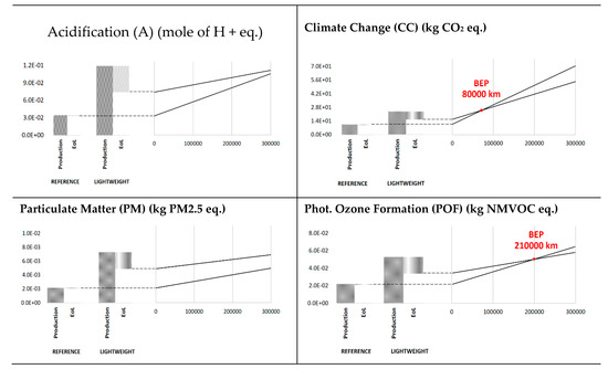
Figure 5.
Break-even point analysis for A, CC, PM and POF impact categories.
BEP diagrams show that at 0 km, the novel solution involves an impact growth for A, CC, PM and POF categories. The only indicators for which the benefit during operation balances out the higher burdens in mileage-independent phases are CC and POF: the impact saving during use is determined through a reduction of CO2 emissions (mainly occurring in TTW) and nitrogen oxide emissions (mainly occurring in WTT), respectively for CC and POF. Concerning CC, the break-even point for the effective convenience of the lightweight design is at a relatively low mileage (about 80,000 km) and the benefit grows at kilometrage increasing, with a 26.3% advantage at 300,000 km. For POF, the equivalence between solutions occurs at around 210,000 km, and the percent impact reduction at 300,000 km is 8.5%. On the other hand, no break-even point occurs for PM and A, where the environmental advantage during operation is not high enough to compensate the greater environmental burdens at 0 km. As a consequence, the reference design appears to be preferable at any LC mileage, with operation only determining a reduction of the gap between steel and aluminum CMS versions (9.7 and 34.5% impact increase at 300,000 km, respectively for A and PM). BEP diagrams are not reported for OD and RD categories. The reason for this is that the influence of use stage is very low with respect to production and EoL (less than 5% of total LC impact for both indicators and design solutions) and therefore, the investigation of impact dependence on LC mileage should not provide any added value with respect to previous diagrams. As a consequence, the environmental effects provided by the lightweight design in mileage-independent LC stages are more or less confirmed at 300,000 km, that are 99.99% OD reduction and 235.0% RD increase.
3.4. Holistic Assessment
As shown in Section 3.2., the lightweight solution provides an impact decrease when considering CC, OD and POF categories, while it involves negative effects for A, PM and RD. As a consequence, the above comparative analysis does not allow to define unequivocally which is the most environmentally preferable design version. In order to overcome this issue, the following provides an integrated assessment of steel and aluminum alternatives by applying the TOPSIS (a Multi-Criteria Decision Analysis, MCDA method) [57] to the overall set of LCIA results reported in Table 4 (decision matrix). Such a method provides a quantitative measure of the effective environmental convenience by taking into account, at the same time, all the selected impact categories, thus enabling to identify which is the best among the two competing solutions.
Table 4.
Decision matrix: LCIA results referring to the entire LC of CMS module.
The TOPSIS analysis is performed by using two different weighting sets (Table 5). In addition to the reference one, where all indicators have the same relative importance, the investigation is performed for the weighting set provided by [58] (WFsA weighting set) for the comparison of the relative importance of ILCD impact categories.
Table 5.
Weighting sets.
Table 6 shows that for both weighting sets the lightweight design is moderately better with respect to the reference one, with value of relative closeness to the ideal solution of about 0.6. It could therefore be concluded that the aluminum CMS module results to be environmentally preferable when considering an integrated assessment of the selected impact categories.
Table 6.
Value of relative closeness to the ideal solution for reference and lightweight design solutions.
4. Conclusions
The paper deals with a lightweight design case study developed within the ALLIANCE innovation and research EU project. The steel baseline version of a rear CMS system module is re-engineered through the introduction of ultra-high-strength aluminum alloys. The adoption of extruded AW 7003 for beam and crash box components makes that the novel alternative provides a very high mass reduction (almost 40%). Concerning the design point of view, 7000 series aluminum alloy as main construction material proves to be a good compromise between strength, production efficiency and design freedom. At the same time, the use of an open beam profile with extrusion design concept specifically developed and customized on material features offers satisfactory results in terms of both lightweight potential and crash-worthiness. On the other hand, the comparative sustainability assessment provides contrasting results on the basis of the specific impact category. The main outcomes of the environmental assessment are reported below through bullet points:
- -
- For all indicators, material change involves an increase in the production impact due to the higher energy intensity and emissions caused by raw material acquisition of 7000 series aluminum alloy with respect to conventional steel. The only exception is represented by OD, for which the production impact of the novel design is almost completely abated due to the drastic drop of trichlorofluoromethane and dichlorotetrafluoroethane emissions in raw material acquisition. Concerning use and EoL phases, the entire set of indicators shows an impact decrease, thanks to, respectively, the reduced FC/emissions during operation and the higher credits of aluminum recycling.
- -
- As regards to total LC, CC and POF are the only categories for which the increased production impacts in mileage-independent phases are counterbalanced by beneficial effects in use, respectively at LC distance of about 80,000 and 210,000 km. On the other hand, the negative effects in production are predominant for A, PM and RD, for which the LC impact grows by 25, 38 and 237% and the break-even point is not reached even for LC mileage higher than 230,000 km. The LC OD saving (close to 100%) is almost exclusively concentrated in production, since around 99% of total impact of the reference CMS is associated with raw material acquisition.
- -
- It can be concluded that for three LCIA categories (CC, OD and POF), the lightweight design entails sustainability benefits while for the other three indicators (A, PM and RD), the steel baseline design appears to be environmentally preferable. That said, the targets, in terms of mass and climate change saving established by the ALLIANCE project, are fully achieved.
- -
- The environmental assessment is completed through the implementation of a MCDA method (TOPSIS) in order to holistically evaluate the competing alternatives on the basis of the entire panel of sustainability criteria. The analysis of the overall environmental profile reveals that the lightweight design solution appears to be slightly convenient for both weighting sets considered.
Author Contributions
F.D.P.: Conceptualization; Data curation; Forma analysis; Investigation; Methodology; Software; Writing original draft; Writing review & editing. M.D.: Funding acquisition; Project administration; Software; Supervision; Writing—review & editing. M.K.: Writing—review & editing. All authors have read and agreed to the published version of the manuscript.
Funding
This research was funded by European Commission grant number 723893.
Acknowledgments
The authors wish to thank all ALLIANCE partners, and, in particular, Jörn Tölle (Benteler Automotive).
Conflicts of Interest
The authors declare no conflict of interest.
Abbreviations
| A | Acidification midpoint |
| ALLIANCE | AffordabLe LIghtweight Automobiles AlliaNCE |
| AM | Additive Manufacturing |
| BIW | Body-In-White |
| CRFPs | Carbon Fiber Reinforced Plastics |
| CC | Climate Change midpoint |
| CMS | Crash Management System |
| EoL | End-of-Life |
| EU | European Union |
| FC | Fuel Consumption |
| FU | Functional Unit |
| GFRPs | Glass Fiber Reinforced Plastics |
| GHG | Greenhouse Gas |
| LC | Life Cycle |
| LCA | Life Cycle Assessment |
| LCI | Life Cycle Inventory |
| LCIA | Life Cycle Impact Assessment |
| NMVOCs | Non-Methane Volatile Organic Compounds Emissions |
| OD | Ozone Depletion midpoint |
| OEMs | Original Equipment Manufacturers |
| PM | Particulate Matter/Respiratory inorganics midpoint |
| POF | Photochemical Ozone Formation midpoint, human health |
| RD | Resource Depletion, mineral, fossils and renewables, midpoint |
| TTW | Tank-To-Wheel |
| WLTP | Worldwide Harmonized Light-Duty Test Procedure |
| WTT | Well-To-Tank |
References
- European Commission. White Paper: Roadmap to a Single European Transport Area—Towards a Competitive and Resource Efficient Transport System; European Commission: Brussels, Belgium, 2011; /* COM/2011/0144 final */. [Google Scholar]
- Nehuis, F.; Kleemann, S.; Egede, P.; Vietor, T.; Herrmann, C. Future Trends in the Development of Vehicle Bodies Regarding Lightweight and Cost. In Innovative Design, Analysis and Development Practices in Aerospace and Automotive Engineering; Springer Science & Business: Berlin/Heidelberg, Germany, 2014; ISBN 978-81-322-1871-5. [Google Scholar] [CrossRef]
- Ferreira, V.; Merchán, M.; Egizabal, P.; García de Cortázar, M.; Irazustabarrena, A.; López-Sabiróna, A.M.; Ferreira, G. Technical and environmental evaluation of a new high performance material based on magnesium alloy reinforced with submicrometre-sized TiC particles to develop automotive lightweight components and make transport sector more sustainable. J. Mater. Res. Technol. 2019, 8, 2549–2564. [Google Scholar] [CrossRef]
- Koffler, C.; Rohde-Brandenburger, K. On the Calculation of Fuel Savings Through Lightweight Design in Automotive Life Cycle Assessments. Int. J. Life Cycle Assess. 2010, 15, 128–135. [Google Scholar] [CrossRef]
- Kim, H.C.; Wallington, T.J. Life Cycle Assessment of Vehicle Lightweight-ing: A Physics-Based Model to Estimate Use-Phase Fuel Consumption of Electrified Vehicles. Environ. Sci. Technol. 2016, 50, 11226–11233. [Google Scholar] [CrossRef]
- Kroll, L.; Blau, P.; Wabner, M.; Frie, U.; Eulitz, J.; Klärner, M. Lightweight Components for Energy-Efficient Machine Tools. CIRP J. Manuf. Sci. Technol. 2011, 4, 148–160. [Google Scholar] [CrossRef]
- Neugebauer, R.; Wabner, M.; Rentzsch, H.; Ihlenfeldt, S. Structure Principles of Energy Efficient Machine Tools. CIRP J. Manuf. Sci. Technol. 2011, 4, 136–147. [Google Scholar] [CrossRef]
- Goede, M. Super Light Car—Lightweight construction thanks to a multi-material design and function integration. Eur. Transp. Res. Rev. 2009, 1, 5–10. [Google Scholar] [CrossRef]
- Ferreira, V. Lightweight automotive components based on nano-diamond-reinforced aluminium alloy: A technical and environmental evaluation. Diam. Relat. Mater. 2019, 2019, 92. [Google Scholar]
- Tisza, M.; Czinege, I. Comparative study of the application of steels and aluminium in lightweight production of automotive parts. Int. J. Lightweight Mater. Manuf. 2018, 1, 229–238. [Google Scholar] [CrossRef]
- Ten Broek, C.; Singh, H.; Hillebrecht, M. Lightweight Design for the Future Steel Vehicle. ATZ Worldw. 2012, 114, 4–11. [Google Scholar] [CrossRef]
- Bian, J.; Mohrbacher, H.; Zhang, J.S.; Zhao, Y.T.; Lu, H.Z.; Dong, H. Application Potential of High Performance Steels for Weight Reduction and Efficiency Increase in Commercial Vehicles. Adv. Manuf. 2015, 3, 27–36. [Google Scholar] [CrossRef]
- Kelly, J.C.; Sullivan, J.L.; Burnham, A.; Elgowainy, A. Impacts of Vehicle Weight Reduction via Material Substitution on Life-Cycle Greenhouse Gas Emissions. Environ. Sci. Technol. 2015, 49, 12535–12542. [Google Scholar] [CrossRef] [PubMed]
- Stamboulis, A.; Baillie, C.A.; Garkhail, S.K.; Van Melick, H.G.H.; Peijs, T. Environmental Durability of Flax Fibres and Their Composites Based on Polypropylene Matrix. Appl. Compos. Mater. 2000, 7, 273–294. [Google Scholar] [CrossRef]
- Papadakis, L.; Schiel, M.; Vassilou, V.; Loizou, A.; Dilger, K. Adhesive Bonding of Attachments on Alternate Car Shell Surfaces in Automotive Final Assembly Lines. Procedia CIRP 2014, 18, 180–185. [Google Scholar] [CrossRef][Green Version]
- Fleischer, J.; Lanza, G.; Tarisai, P.; Möhring, H.; Teti, R.; Caggiano, A. Composite Materials Parts Manufacturing. CIRP Ann.—Manuf. Technol. 2018, 67, 603–626. [Google Scholar] [CrossRef]
- Meschut, G.; Janzen, V.; Olfermann, T. Innovative and Highly Productive Joining Technologies for Multi-Material Lightweight Car Body Structures. J. Mater. Eng. Perform. 2014, 23, 1515–1523. [Google Scholar] [CrossRef]
- Duflou, J.R.; De Moor, J.; Verpoest, I.; Dewulf, W. Environmental Impact Analysis of Composite Use in Car Manufacturing. CIRP Ann.—Manuf. Technol. 2009, 58, 9–12. [Google Scholar] [CrossRef]
- Duflou, J.R.; Deng, Y.; Van Acker, K.; Dewulf, W. Do Fiber-Reinforced Polymer Composites Provide Environmentally Benign Alternatives? A Life-Cycle-Assessment-Based Study. MRS Bull. 2012, 37, 374–382. [Google Scholar] [CrossRef]
- Song, Y.S.; Youn, J.; Gutowski, T.G. Life Cycle Energy Analysis of Fiber-Reinforced Composites. Compos. Part A Appl. Sci. Manuf. 2009, 40, 1257–1265. [Google Scholar] [CrossRef]
- Shishoo, R. The Global Textile and Clothing Industry; Woodhead Publishing Limited: Cambridge, MA, USA, 2012. [Google Scholar]
- Soo, V.K.; Compston, P.; Subic, A.; Doolan, M. The Impact of Different Joining Decisions for Lightweight Materials on Life Cycle Assessment. In Proceedings of the AutoCRC 3rd Technical Conference, January 2014. [Google Scholar]
- Ashby, M. Materials selection in mechanical design: Fourth edition. In Materials Selection in Mechanical Design, 4th ed.; Butterworth-Heinemann: Oxford, UK, 2010; pp. 1–646. ISBN 9780080952239. [Google Scholar]
- Helou, M.; Kara, S. Design, Analysis and Manufacturing of Lattice Structures. Int. J. Comput. Integr. Manuf. 2017, 31, 243–261. [Google Scholar] [CrossRef]
- Ghoreishi, R.Z.; Roohi, A.H.; Ghadikolaei, A.D. Evaluation of tool wear in high-speed face milling of Al/SiC metal matrix composites. J. Braz. Soc. Mech. Sci. Eng. Vol. 2019, 41, 146. [Google Scholar] [CrossRef]
- Mehrpouya, M.; Dehghanghadikolaei, A.; Fotovvati, B.; Vosooghnia, A.; Emamian, S.; Gisario, A. The Potential of Additive Manufacturing in the Smart Factory Industrial 4.0: A Review. Appl. Sci. 2019, 9, 3865. [Google Scholar] [CrossRef]
- Kellens, K.; Baumers, M.; Gutowski, T.G.; Flanagan, W.; Lifset, R.; Duflou, J.R. Environmental Dimensions of Additive Manufacturing: Mapping Application Domains and Their Environmental Implications. J. Ind. Ecol. 2017, 21, S49–S68. [Google Scholar] [CrossRef]
- Arankalle, A. Advances in lightweight materials for body in white. Innovative Design and Development Practices in Aerospace and Automotive Engineering, Lecture Notes in Mechanical Engineering; Springer: Singapore, 2016; pp. 517–525. [Google Scholar]
- Beiter, P.; Groche, P. On the Development of Novel Light Weight Profiles for Automotive Industries by Roll Forming of Tailor Rolled Blanks. Key Eng. Mater. 2011, 473, 45–52. [Google Scholar] [CrossRef]
- Ingarao, G.; Di Lorenzo, R.; Micari, F. Sustainability Issues in Sheet Metal Forming Processes: An Overview. J. Clean. Prod. 2011, 19, 337–347. [Google Scholar] [CrossRef]
- Allwood, J.M.; Kong, H.; Pole, N. Sustainable Materials—With Both Eyes Open; UIT Cambridge: Cambridge, UK, 2012. [Google Scholar]
- Wiesbaden, S.F. InCar plus: Solutions for Automotive Efficiency. Atzextra Worldw. 2014, 19, 8–9. [Google Scholar] [CrossRef]
- Merklein, M.; Johannes, M.; Lechner, M.; Kuppert, A. A Review on Tailored Blanks—Production, Applications and Evaluation. J. Mater. Process-Sing Technol. 2014, 214, 151–164. [Google Scholar] [CrossRef]
- Carle, D.; Blount, G. The Suitability of Aluminium as an Alternative Material for Car Bodies. Mater. Des. 1999, 20, 267–272. [Google Scholar] [CrossRef]
- Del Pero, F.; Delogu, M.; Fernandez, V.; Ierides, M.; Seidel, K.; Thirunavukkarasu, D. Lightweight Design Solutions in the Automotive Sector: Impact Analysis for a Door Structure. In Sustainable Design and Manufacturing; KES-SDM 2019. Smart Innovation. Systems and Technologies; Springer: Singapore, 2019; Volume 155. [Google Scholar] [CrossRef]
- Del Pero, F.; Delogu, M.; Berzi, L.; Dattilo, C.A.; Zonfrillo, G.; Pierini, M. Sustainability assessment for different design solutions within the automotive field. Procedia Struct. Integr. 2019, 24, 906–925. [Google Scholar] [CrossRef]
- Herrmann, C.; Dewulf, W.; Hauschild, M.; Kaluza, A.; Kara, S.; Skerlos, S. Life cycle engineering of lightweight structures. CIRP Ann. 2018, 67, 651–672. [Google Scholar] [CrossRef]
- Modaresi, R.; Pauliuk, S.; Lövik, A.N.; Müller, D.B. Global Carbon Benefits of Material Substitution in Passenger Cars until 2050 and the Impact on the Steel and Aluminum Industries. Environ. Sci. Technol. 2014, 48, 10776–10784. [Google Scholar] [CrossRef] [PubMed]
- Hardwick, A.P.; Outteridge, T. Vehicle Lightweighting Through the Use of Molybdenum-bearing Advanced High-strength Steels (AHSS). Int.-AL J. Life Cycle Assess. 2016, 21, 1616–1623. [Google Scholar] [CrossRef]
- Kim, H.-J.; McMillan, C.; Keoleian, G.A.; Skerlos, S.J. Greenhouse Gas Emissions Payback for Lightweighted Vehicles Using Aluminum and High-Strength Steel. J. Ind. Ecol. 2010, 14, 929–946. [Google Scholar] [CrossRef]
- Kim, H.C.; Wallington, T.J. Life-Cycle Energy and Greenhouse Gas Emission Benefits of Lightweighting in Automobiles: Review and Harmonization. Environ. Sci. Technol. 2013, 47, 6089–6097. [Google Scholar] [CrossRef] [PubMed]
- Paraskevas, D.; Kellens, K.; Renal Dewulf, W.; Duflou, J.R. Closed and Open Loop Recycling of Aluminium: A Life Cycle Assessment Perspective. In Proceedings of the 11th Global Conference on Sustainable Manufacturing, Berlin, Germany, 23–25 September 2015; pp. 302–307. [Google Scholar]
- Cui, J.; Roven, H.J. Recycling of Automotive Aluminum. Trans. Nonferrous Met. Soc. China 2010, 20, 2057–2063. [Google Scholar] [CrossRef]
- Del Pero, F.; Delogu, M.; Pierini, M.; Kerschbaum, M.; Tölle, J. Design and Sustainability Assessment of Lightweight Concept for an Automotive car Module; SAE Technical Paper; SAE International: Warrendale, PA, USA, 2020; in press. [Google Scholar]
- Delogu, M.; Del Pero, F.; Zanchi, L.; Ierides, M.; Fernandez, V.; Seidel, K.; Thirunavukkarasu, D.; Bein, T. Lightweight Automobiles ALLIANCE Project: First Results of Environmental and Economic Assessment from a Life-Cycle Perspective; SAE Technical Paper 2018-37-0027; SAE Technical Paper; SAE International: Warrendale, PA, USA, 2018. [Google Scholar] [CrossRef]
- RCAR Low-Speed Structural Crash Test Protocol. Available online: http://rcar.org/Papers/Procedures/RCAR%20Structure%20Test%20procedure%20Version%202_3.pdf#zoom=80% (accessed on 5 June 2020).
- EC-JRC. International Reference Life Cycle Data System (ILCD) Handbook-Recommendations for Life Cycle Impact Assessment in the European Context; Publications Office of the European Union: Brussels, Belgium, 2011; ISBN 978-92-79-17451-3. [Google Scholar]
- ISO 14040/14044, 2006. Environmental Management e Life Cycle Assessment Principals and Framework/Requirements and Guidelines; ISO: Geneva, Switzerland, 2006. [Google Scholar]
- Weymar, E.; Finkbeiner, M. Statistical analysis of empirical lifetime mileage data for automotive LCA. Int. J. Life Cycle Assess. 2016, 21, 215–223. [Google Scholar] [CrossRef]
- Mock, P.; Kühlwein, J.; Tietge, U.; Franco, V.; Bandivadekar, A.; German, J. The WLTP: How a new test procedure for cars will affect fuel consumption values in the EU. Work. Pap.—Int. Counc. Clean Transp. 2014, 9, 35–47. [Google Scholar]
- Sphera, GaBi6 Software. 2020. Available online: http://www.gabi-software.com/italy/index/ (accessed on 10 April 2020).
- Enhanced Lightweight Design, ENLIGHT Project. Available online: https://cordis.europa.eu/project/id/314567 (accessed on 7 September 2019).
- E-Mobility Life Cycle Assessment Recommendations, e-LCAr Project. Available online: http://www.elcar-project.eu/ (accessed on 9 December 2019).
- Del Pero, F.; Delogu, M.; Pierini, M. The effect of lightweighting in automotive LCA perspective: Estimation of mass-induced fuel consumption reduction for gasoline turbocharged vehicles. J. Clean. Prod. 2017, 154, 566–577, ISSN 0959-6526. [Google Scholar] [CrossRef]
- Directive 2000/53/EC on End-of-Life Vehicles European Commission. Available online: https://eur-lex.europa.eu/legal-content/EN/ALL/?uri=CELEX%3A32000L0053 (accessed on 20 September 2019).
- ISO 22628. Road Vehicles, Recyclability and Recoverability Calculation Method; ISO: Geneva, Switzerland. Available online: https://www.iso.org/standard/35061.html (accessed on 4 May 2020).
- El Amine, M.; Pailhes, J.; Perry, N. Critical Review of Multi-criteria Decision Aid Methods in Conceptual Design Phases: Application to the Development of a Solar Collector Structure. Procedia CIRP 2014, 21, 497–502. [Google Scholar] [CrossRef]
- Castellani, V.; Benini, L.; Sala, S.; Pant, R. A distance-to-target weighting method for Europe 2020. Int. J. Life Cycle Assess. 2016, 21, 1159–1169. [Google Scholar] [CrossRef]


© 2020 by the authors. Licensee MDPI, Basel, Switzerland. This article is an open access article distributed under the terms and conditions of the Creative Commons Attribution (CC BY) license (http://creativecommons.org/licenses/by/4.0/).