Article

Synthesis of Sustainable Circular Economy in Palm Oil Industry Using Graph-Theoretic Method

1
Research Centre for Sustainable Technologies, Faculty of Engineering, Computing and Science, Swinburne University of Technology, Jalan Simpang Tiga, Kuching 93350, Malaysia
2
Institute of Process Engineering & NETME Centre, Brno University of Technology, Technicka 2896/2, 61669 Brno, Czech Republic
3
Department of Chemical and Environmental Engineering, University of Nottingham Malaysia Campus, Jalan Broga, Semenyih 43500, Selangor, Malaysia
4
Department of Chemical Engineering, Curtin University Malaysia, CDT 250, Miri 98009, Malaysia
5
Department of Chemical Engineering, Universiti Tunku Abdul Rahman, Jalan Sungai Long, Bandar Sungai Long, Cheras, Kajang 43000, Malaysia
6
UKM-Graduate School of Business, Universiti Kebangsaan Malaysia, UKM, Bangi 43600, Malaysia
*
Author to whom correspondence should be addressed.
Sustainability 2020, 12(19), 8081; https://doi.org/10.3390/su12198081
Submission received: 5 August 2020 / Revised: 26 September 2020 / Accepted: 28 September 2020 / Published: 30 September 2020
(This article belongs to the Special Issue Sustainable Supply Chain Management for Process Industry)

Abstract

:
Huge generation of oil palm biomass has stimulated the development of biorefineries for synthesis of bioproducts. By targeting the palm oil industry and the biorefineries as the consumers of these products, a sustainable circular economy can be created by recycling the biomass wastes to the said consumers. To evaluate the techno-economic feasibility of the sustainable circular economy, a mathematical model demonstrating the biomass network with consideration of recycling is developed in this work. Besides, Process Graph (P-graph) is incorporated to perform the combinatorial optimization of the biomass network, which targets three common resources: fertilizer, steam, and electricity for regeneration and recycling. Although the result shows that the linear economy model is preferred in terms of profitability, the circular economy model shows potential in reducing 39.292% of the imported steam and 13.469% of the imported electricity, while being 0.642% lower in terms of the gross profit. Three scenarios are then proposed to identify the potential bottleneck that can hinder the implementation of the sustainable circular economy approach, with the aid of sensitivity analysis. This work is expected to benefit the biomass-based industry sectors and the policymakers on future development and transition to the sustainable circular economy.

1. Introduction

Palm oil has shown versatile applications in both edible and non-edible use. While it is commonly found in food and oleochemical industries, the rising application of palm oil in recent years is the synthesis of biodiesel. Given its unique fatty acid profile, palm oil-derived biodiesel has been shown to have better flow properties and lower emission of nitrogen oxides during combustion compared with those derived from vegetable oils [1]. Being a renewable fuel that is derived from biomass, the application of palm oil biodiesel notably in transportation was popular especially in European countries around year 2008 to 2018. In the year 2018, over 50% of the palm oil consumption in European countries came from the production of biodiesel, and that was just under 20% a decade ago [2]. On top of that, oil palm is also highly efficient in terms of the oil yield per land used that is measured in ton per hectare (t/ha). A typical oil palm generates about 3.84 t/ha, which is about 6 to 9 times more efficient than other oil crops, such as soybean (0.45 t/ha), sunflower (0.50 t/ha), and rapeseed (0.66 t/ha) [3]. With the widespread applications and extraordinary efficiency, this has led to the substantial growth in the palm oil industry especially in Borneo countries like Indonesia and Malaysia. Furthermore, the labor-intensive nature of the said industry also helps tackle the poverty in these countries due to the enormous demand [4]. In the case of Malaysia, the production of crude palm oil (CPO) has increased from roughly 10 million tons (Mt) to 19.9 Mt, whereas the plantation area has expanded from 3.3 million hectares (Mha) to 5.9 Mha in a span of two decades from 2000 to 2019 [5,6].
Conversely, the palm oil industry has raised some environmental issues, such as deforestation and waste generation. The first issue has particularly caused the backlash by the European countries, which started refusing the palm oil products despite being one of the largest consumers of CPO. Concurrently, the effort of phasing out the palm oil can be disadvantageous given its benefits as stated above. Thus, to minimize the impact of deforestation, Roundtable on Sustainable Palm Oil (RSPO) emerged as a global organization that encourages the sustainable source of palm oil by certifying the supply chain model. Similar certification bodies, such as Indonesian Sustainable Palm Oil (ISPO) and Malaysian Sustainable Palm Oil (MSPO), were also made mandatory to the local palm oil industries to ensure sustainable practices on a national scale [7,8]. Besides, the Malaysian government also announced a policy to limit the plantation area at 6.5 Mha by 2023 as an effort to halt deforestation [9]. On the other hand, the palm oil industry may also cause environmental pollutions if not treated properly. In particular, every ton of CPO can be associated with 9 tons of biomass, which translates to roughly 179 Mt of biomass in Malaysia as of 2019 [10]. Additionally, the palm oil industry has contributed up to 77% of the total agricultural wastes in Peninsular Malaysia [11]. This includes oil palm frond (OPF) and oil palm trunk (OPF) from the oil palm plantation, and subsequently empty fruit bunches (EFB), mesocarp fiber (MF), palm kernel shell (PKS), and palm oil mill effluent (POME) from the palm oil mill. The composition of the oil palm biomass is illustrated in Figure 1.
Nonetheless, the waste generation issue can be viewed as an opportunity rather than as a threat to the palm oil industry, unlike the deforestation issue. In reality, numerous conversion technologies have been gradually developed and commercialized to better utilize the wastes, such as the synthesis of biofuel and biochemical. On the other hand, the palm oil industry itself can act as a point of demand to increase the consumption of its wastes [13]. In general, the palm oil industry requires input resources, such as fertilizer, steam, fuel, and electricity [14]. These resources can be generated from the biomass using appropriate biomass conversion technologies or biorefineries in short. Thus, by using the right biorefineries, a circular economy or circularity approach can be developed around the palm oil industry by connecting its output wastes to the input resources [15] or closing the loop in short [16,17]. From the physical point of view, the concept of sustainable circular economies can be seen as an attempt to reduce the outflow of material from the system; in this case, the biomass is the material, while the palm oil industry is the system. Meanwhile, the current palm oil industry in Malaysia mainly adopts the linear economy that uses the ‘make-use-dispose’ model. For instance, the solid wastes, such as OPF and OPT, have commonly been disposed to the plantation for natural decomposition [14], whereas the liquid wastes or POME have been mainly treated using an open pond system without biogas capturing [18]. These conventional means of handling can be deemed inefficient as it does not harness the potential economic profits, which signifies the loss of resources as an outcome of this make-use-dispose model [19]. Therefore, there is a need to effectively utilize these biomasses, whereby the concept of circularity can be introduced to the palm oil industry for creating a self-regenerative system and, thus, better sustainability.
By integrating these biorefineries into the palm oil industry, a biomass network can be created around the industry, which describes the conversion and recycling pathways of the biomass. For that, combinatorial optimization is needed to determine the optimal configuration of the biomass network based on the given objectives. Mixed Integer Linear Programming (MILP) is one of the mathematical programming techniques that has been used to perform the optimization. For instance, MILP was used to optimize the wastes allocation and determine the optimum conversion technologies in the waste-to-energy supply network [20]. Besides, MILP was implemented to minimize the logistic costs and carbon emission in the bioenergy supply chain based on the regional palm oil industry [21]. Moreover, MILP was applied to maximize the economic performances of the integrated palm oil processing complex owned by a single owner [22], as well as multiple owners to achieve industrial symbiosis [23]. On the other hand, another graph-theoretic approach—Process Graph (or P-graph in abbreviation)—has shown numerous applications in combinatorial optimization particularly in process integration [24]. While the graphical user interface eases the modeling process, another benefit is the ability to generate multiple sub-optimal solutions for further analysis. For example, P-graph was utilized to optimize the economic performance of the integrated biorefinery network in the design of multiple biomass corridors [25]. In Reference [26], a biomass supply chain was also optimized using sustainability indicators as the objective function, whereas the suboptimal solutions were further utilized to demonstrate the debottlenecking strategy. Lam et al. [27] modeled a biomass supply chain network using P-graph to maximize the production of bioenergy and bioproducts in the Central European setting. From their work, the result of optimization by P-graph is compared with that of MILP, whereby high similarity was observed on both results, while the minimal differences can be attributed to rounding [27]. Meanwhile, research on combinatorial optimization with recycling stream is still considered lacking particularly in the case of biomass network. A thorough search of the relevant literature yielded only one related study using MILP, which has considered the reverse flow of EFB for mulching and combustion [28]. However, the application of the chosen biomass in recycling is quite limited in the context of circularity, while most studies related to biomass or integrated biorefinery network synthesis using P-graph are generally lacking the element of circularity. In this paper, P-graph is proposed to synthesize a palm oil-based biomass network, while incorporating the recycling flow of material and energy. Other physical concepts or simulators are also used as a supplementary tool to compute some parameters if such data is unavailable.
The paper is organized as follows: Section 2 outlines the problem statement of the model, whereas Section 3 describes the method used in this paper. The description of the case study is given in Section 4. Then, the results and discussions are highlighted in Section 5, followed by a concluding remark in Section 6.

2. Problem Statement

The oil palm biomass can be thought of as a reservoir of bioproducts, such as material, chemical, and energy. Various biorefineries in the forms of physical, biochemical, and thermochemical processes can be used to derive these bioproducts depending on the type of input biomass and the end-use purpose. Physical processes usually involve size reduction and moisture removal during the extraction of the material. Besides, biochemical and thermochemical processes utilize different driving forces for reactions and extractions. For instance, the former uses biological treatment for degradation, whereas the latter uses heat for decomposition. Table 1 summarizes the potential and commercialized biorefineries for oil palm biomass in Malaysia. The degree of freedom in terms of choosing the biorefineries increases by considering all of them highlighted in Table 1, as well as the recycle flow of the bioproducts. Graphically, this resembles a many-to-many relationship as some biorefineries are connected to multiple inputs and outputs. Moreover, some technologies are considered as competitors to the implementation of circularity as the products are often exported to the external markets rather than being recycled and consumed in the industry (i.e., fiber, bioethanol, activated carbon). Thus, the biomass network model needs to be optimized to determine the optimal combination of the biorefineries in realizing the concept of circularity.
The formal description of the model is given as follows. A set of waste w is generated in sites a and collected by biorefinery b . These wastes w are then processed using a series of technologies t and t to generate the final products p with the involvement of intermediates i . Next, there are two possible outcomes of the final products p . It can be either exported to customers d to generate income for the industry. Or, it can be transferred to recycle c for further processing via a series of technologies r and r with the involvement of intermediates j . The outcome of the recycle c is the regenerated resources s , which are then consumed in sites a , technologies t and t to sustain the operation. Alternatively, the resources s can also be imported from external suppliers. To note, the regenerated resources s is assumed to be compatible and replaceable with the corresponding imported resources. A superstructure of the model is illustrated in Figure 2.
In this case, both linear and circular economy model can be generated from the superstructure based on the flow of materials. For instance, the model is regarded as circular if the recycling pathways are selected in c to regenerate and recycle the resources, i.e., a b c a , b ; and the cycle continues as a loop. Otherwise, the model is considered as linear if all the materials end at d for export, i.e.,   a b d . Meanwhile, the demand for imported resources s can be reduced by increasing the regenerated resources s . This resembles the concept of the sustainable circular economy that serves to minimize the input resources. With that, biorefinery b and recycle c are the main focus of combinatorial optimization, whereby the goal is to maximize the economic performances of the model.

3. Method

The procedure of the work is described as follows. First, it is initiated by collecting the data and parameters regarding the palm oil industry and biorefineries. Next, the model formulation representing the generic superstructure in Figure 2 is created to describe the palm oil industry’s combinatorial optimization. Then, a biomass network is modeled and optimized using the P-graph Studio [31]. After the optimized result is obtained, a series of sensitivity analysis is performed to generate further implications. The detailed description of the procedure is provided as follows.

3.1. Data Collection

The first step is to identify the available conversion technologies with local settings in Malaysia. This includes conventional methods, such as direct combustion of MF and PKS for heat generation, as well as other commercialized and potential technologies. The life cycle of the palm industry, as well as the biorefineries, are then assessed to obtain two types of parameters: (i) The conversion ratio of inputs to outputs, and (ii) the expenses, such as capital (CAPEX) and operating (OPEX) expenses.
The scope of the palm oil industry includes the oil palm plantation and palm oil mill, both of which act as the source of biomass. The economic performance of these two sectors will not be assessed as their operations occur before the biomass conversion in the biorefineries. In other words, the profit and expenses are considered as constant regardless of which combination of biorefineries are chosen, i.e., they do not affect the result of optimization. However, the input resources of these sectors, such as steam, electricity, and fertilizer, are assessed to allow the integration of recycle flow of these materials. In the case of biorefineries, the CAPEX and OPEX must be assessed as they are a few of the major factors in combinatorial optimization. Furthermore, the usage of steam and electricity is separated from their OPEX and listed as input parameters if such data were available. Similarly, this is to allow the integration of the recycle flows of steam and electricity for modeling and optimization.
These parameters are mostly obtained from research works related to the circular economy or the palm oil industry. Some recent processes and supply chain configurations are supplemented by the government and business reports. On the other hand, several assumptions and simulations are used to approximate the parameters, such as conversion ratio, if unavailable. This includes the manipulation of certain information, such as the properties of the material and the operating conditions of the technology.

3.2. Model Formulation

The optimization of the superstructure in Figure 2 is carried out by P-graph Studio based on a series of formulations as follows:
Constraint (1) is used to ensure the total flowrate of waste w sending to all biorefineries b ( b F w , a , b ) are capped at availability limit at each site ( F w , a ) :
b F w , a , b F w , a     w W , a A .
The amount of waste w collected in each biorefinery b ( F w , b ) is then computed using Equation (2), while Equation (3) describes the mass balance of the collected waste w at technology t :
F w , b = a F w , a , b     w W , b B ,
t F w , b , t = F w , b     w W , b B ,
where F w , b , t denotes the flowrate of waste w to be consumed by technology t at biorefinery b .
The production rates of intermediate i ( F i , b ) and product p ( F p , b ) at biorefinery b are then determined using Equations (4) and (5), respectively:
F i , b = w t ( F w , b , t × X w , t , i )     i I , b B ,
F p , b = i t ( F i , b , t × X i , t , p )   p P , b B ,
where X w , t , i and X i , t , p refer to the conversion ratios of waste w to intermediate i and intermediate i to product p at respective technology t and t . It is worth noting that not all pathways are involved with an intermediate material. In that case, X i , t , p can be set as 1 so F p , b = i t F i , b , t . Meanwhile, F i , b , t denotes the consumption rate of intermediate i by technology t that is expressed in Equation (6):
t F i , b , t = F i , b     i I , b B .
Next, the collected product p is either sent to recycle c for further utilization or sold to customer d for profit. For that, Equation (7) denotes the distribution of product p to both sectors:
F p , b = c F p , b , c + d F p , b , d     p P , b B ,
where F p , b , c and F p , b , d are the flowrates of product p distributed to sectors c and d , respectively.
From there, Equations (8) and (9) describes the amount of product p received at recycle c ( F p , c ) and customer ( F p , d ) , respectively:
F p , c = b F p , b , c     p P , c C ,
F p , d = b F p , b , d     p P , d D .
At recycle c , Equation (10) describes the mass balance of product p collected by technology r ( F p , c , r ) , followed by Equations (11) and (12), which determine the production rates of intermediate j ( F j , c ) and resource s ( F s , c ) , respectively:
r F p , c , r = F p , c     p P , c C ,
F j , c = p r ( F p , c , r × X p , r , j )     j J , c C ,
F s , c = j r ( F j , c , r × X j , r , s )     s S , c C ,
where X p , r , j refers to the conversion ratios of product p to intermediate j by technology r , and X j , r , s refers to intermediate j to regenerated resource s by technology r . Likewise, the conversion ratios can be set as 1 if no intermediates are involved. Meanwhile, F j , c , r denotes the consumption rate of intermediate j by technology r , which is shown in Equation (13):
r F j , c , r = F j , c     j J , c C .
On the other hand, the demand of the resource needed in a given biomass network is defined as the sum of the imported and regenerated resources. Let this resource demand be F s D e m a n d , the flowrate of imported resources s required by the biomass network ( F s I m p o r t ) will be conveniently expressed in Equation (14) as follows:
F s I m p o r t = F s D e m a n d c F s , c     s S .
In this biomass network, F s D e m a n d can be determined using Equation (15). The first term shows the consumption rate of resource s , which is determined by multiplying the processing rate of fresh fruit bunches (FFB) ( F a F F B ) with a scale factor k s , a F F B . As for technology t and t , the respective consumption rates are determined by multiplying the processing rate of waste w ( F w , b , t ) and intermediate i ( F i , b , t ) with scale factors k s , w , t and k s , i , t , respectively. The total consumption rate of resource s then represents the resource demand of the biomass network, which is expressed in Equation (15):
F s D e m a n d = a ( F a F F B × k s , a F F B ) + w b t ( F w , b , t × k s , w , t ) + i b t ( F i , b , t × k s , i , t )     s S .
Next, the gross profit ( C G P ) of the biomass network is calculated by subtracting the costs of imported resources ( C I R ) and technology expenses (CAPEX: C C X ,   t o t a l ; OPEX: C O X ,   t o t a l ) from the sales of exported products ( C E P ) . Equations (16) and (17) represent the calculations of C I R and C E P , which are obtained by multiplying the unit cost ( C p , C s ) with the respective flowrates ( F p , d , F s ):
C E P = p d ( F p , d × C p ) ,
C I R = s ( F s × C s ) .
As for C C X ,   t o t a l and C O X ,   t o t a l , both are assumed to be proportional to the processing rate of input materials at each technology. Thus, C C X ,   t o t a l is calculated by multiplying the processing rate of input materials with scale factors ( C t C X , C t C X , C r C X , C r C X ) at respective technology t , t , r , and r , which is expressed in Equation (18):
C C X ,   t o t a l = w b t ( F w , b , t × C t C X ) + i b t ( F i , b , t × C t C X ) + p c r ( F p , c , r × C r C X ) + j c r ( F j , c , r × C r C X ) .
Similarly, Equation (19) calculates the C C X ,   t o t a l using the scale factors C t O X , C t O X , C r O X , C r O X :
C O X ,   t o t a l = w b t ( F w , b , t × C t O X ) + i b t ( F i , b , t × C t O X ) + p c r ( F p , c , r × C r O X ) + j c r ( F j , c , r × C r O X ) .
Lastly, C G P is maximized by the P-graph optimization using Equation (20), which forms the basis in the ranking of each solution structure as follows:
max C G P = C E P C I R C C X , t o t a l C O P , t o t a l .
To focus on the economic performance of the conversion and recycling pathways, factors of site location, such as cost of transportation, land, construction, etc., will be omitted from this work. Once the configuration of biomass network is identified, these factors can be incorporated into the model later to obtain a more practical gross profit.
On the other hand, the supplementary formulation of steam and electricity generation is given in Equations (21)–(23) as described here. The energy consumption in steam generation E i n . and electricity generation from steam E e is approximated by taking the difference of enthalpies H . Additional considerations for operational units, such as the efficiency of the boiler and turbine, are accounted for the steam and electricity generation. Based on Reference [32], the efficiencies are taken at 80% for the boiler and 100% for the turbine (rounded from 99.625%). In this case, E i n and E e are simulated using Aspen HYSYS V10 [33].
E i n , H P S = H H P S H w a t e r 0.8 ,
E i n , M P S = H M P S H w a t e r 0.8 ,
E e = H H P S H M P S .
In addition, the operating conditions of the water and steam are taken from the recommendation by Reference [32] as follows: (i) ambient water: 1 bar and 30 °C, (ii) medium pressure steam (MPS): 10 bar and 200 °C, and (iii) high pressure steam (HPS): 48 bar and 350 °C. Note that this MPS can be used for other purposes, such as heating, drying, sterilization, etc., to fulfill the steam demand of the technologies.

3.3. P-graph Modeling of Biomass Network

P-graph is a type of bipartite graph that consists of two types of vertices: material vertex M (including raw material, intermediate, and final product) denoted as a dot and operating unit vertex O denoted as a rectangular bar. The general rule in P-graph modeling is to only connect M to O or O to M by arcs, whereas the arc represents the direction of the material flowrate. In particular, five axioms [34] must be satisfied to generate a viable mathematical model as follows:
  • The final product must be displayed in the model.
  • M vertex must be a raw material if it has no input arcs.
  • Every O vertex must be well-defined by the input and output arcs.
  • Every O vertex must be connected in such a way that it leads to the final product vertex.
  • Every M vertex must be an input or output of the O vertex.
In the P-graph framework, all the operating units are treated as a black box, whereby the inputs and outputs are related by the conversion ratio of output to input. Besides, additional attributes, such as flowrate constraint and costs, can be embedded into every M and O vertex if necessary, which are then evaluated alongside with the conversion ratios during the optimization. On the other hand, three algorithms are developed to manage the axioms [35]. Firstly, Maximal Structure Generation (MSG) algorithm provides a graphical overview of the process network that is rigorously defined in mathematics. Secondly, the Solution Structure Generation (SSG) algorithm generates all the possible solutions that link all the raw materials and the final products. Thirdly, Accelerated Branch and Bound (ABB) algorithm, is applied, which is an enhanced version of the branch and bound algorithm to perform combinatorial optimization. Each solution structure is then ranked accordingly based on the objective function.
Note that the algorithms and calculations are executed in the backend processes, whereas the user only needs to generate the model by connecting the vertices. Given its graphical user interface and self-explanatory axioms, this makes P-graph a friendly approach in process network synthesis that is suitable for the actors in industries and policymakers where advanced programming knowledge is not required. With that, 
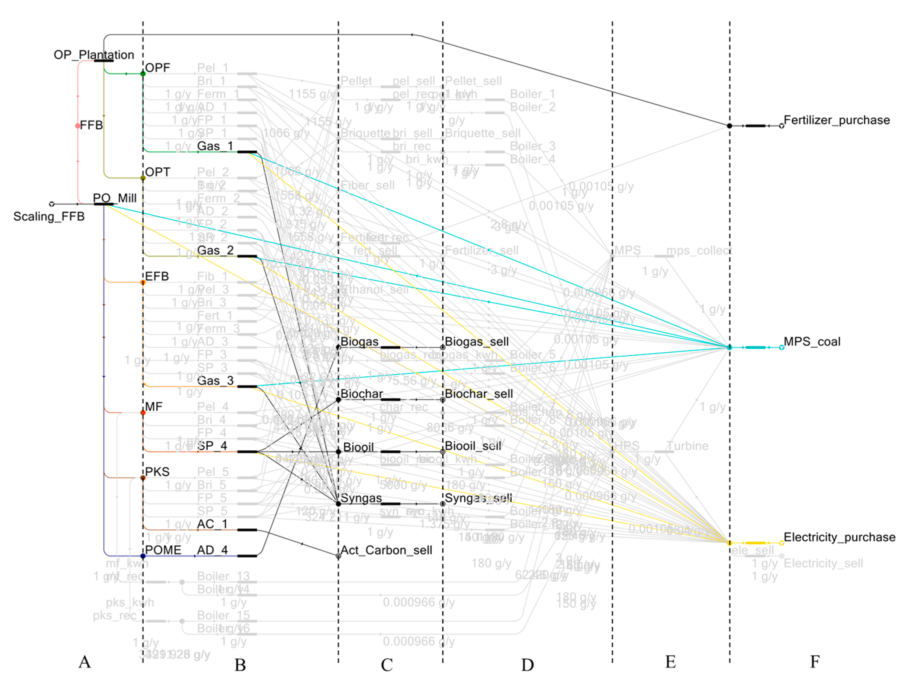
Figure 3 illustrates a generic biomass network that is modeled in the P-graph framework. For better visualization, this biomass network is divided vertically into six sections at the intermediate material vertices as shown in Figure 3.
Starting from the left, section A represents the generation of biomass, which resembles the site a in the superstructure. The life cycle of the industry is assessed to identify the distribution of the biomass. Next, sections B and C are involved with the conversion of wastes to products, which resembles biorefinery b in the superstructure. More precisely, section B represents the decision-making on choosing the right technologies, whereas section C represents the decision-making on the outcome of the product that is to sell or recycle.
Moving on, sections D and E represent the recycle c , which is involved in the handling processes of products into useful resources. Three resources: fertilizer, MPS, and electricity are taken as an example in the illustration of these sections. In this example, D can be described as the decision-making on generating MPS or HPS, whereas section E represents the outcome of the decision made in the previous section. If the product is used as a biofuel and the HPS route is chosen (shown in red), both electricity and MPS are generated using turbine and then collected at the end of section E. Otherwise, only MPS is collected if the MPS route is selected (shown in blue), which requires lesser fuel compared to the formal route. On the other hand, if the product is used as a fertilizer, it will be collected at the end of E without needing further conversions. In short, the design of sections D and E may or may not require the operating units depending on the end-use of the products.
Lastly, section F represents the management of resources. Considering the same example, these resources would be fertilizer, MPS, and electricity. In this case, fertilizer and MPS can only be imported, whereby the MPS is ‘imported’ through the combustion of imported fuel. Besides, electricity can be either imported at a set price or exported if any excess were found and is profitable. In other words, electricity can be seen as a product for export or a resource for recycling. All the imported and regenerated resources are ‘collected’ at the checkpoint between section E and section F, which are then distributed to the operating units in sections A and B.
Similar to the generic superstructure, both linear and circular economic model can be obtained from the biomass network model by observing the material flow. For example, the model is considered as linear if the material flows from F→A→B→C where all products are exported without recycling. On the other hand, circularity is observed if a loop is formed. Using the above example, loop F→A→B→C→D→E→F will be observed if the steam and electricity are regenerated, whereas loop F→A→B→C→F will be observed in the case of fertilizer production and recycling.

3.4. Sensitivity Analysis

After the maximal structure of the biomass network is modeled and optimized using P-graph, sensitivity analysis is performed to observe the changes in decision-making under sections B, C, and D. The analysis is initiated by creating a scenario, whereby an expected solution is predetermined based on the theme of the scenario. Often these expected solutions can be found in the list of suboptimal solutions generated by the SSG algorithm. Next, a range of numerical values is given to one (or multiple) targeted parameter that is relevant to the theme. After that, the targeted parameter(s) are adjusted at a set increment or decrement depending on the starting value, followed by the P-graph optimization to obtain the updated result. The process is then repeated to observe the change in the ranking of the expected solution.
If the theme of a scenario represents a decisive goal (e.g., to introduce or debottleneck a given pathway), the goal is considered to succeed if the expected solution becomes optimal (Rank 1) within the range of testing. The testing can be repeated by targeting another parameter relevant to the theme until the goal is achieved. Otherwise, the goal is considered failed if the expected solution was only optimal outside the range of all tested parameters. Alternatively, the result can be unbiased if the theme represents a neutral investigation created from the observation on the suboptimal solutions. In that case, the testing can be conducted using an unlimited range of parameter values until the expected solution becomes optimal and fulfills the theme of the investigation. Figure 4 illustrates the sensitivity analysis in the form of a flow chart.

4. Case Study Description

A conceptual area owned by a single owner or corporation is considered with a local setting in Malaysia. This area includes an oil palm plantation field, a palm oil mill, and a few biorefineries to be integrated with the upstream activities. The processing rate of FFB in a palm oil mill determines the generation of biomass, while indirectly decides the size of the plantation. For that, it is set at a moderate capacity of 60 t/h. The properties of the biomass, such as dry mass content and calorific value, are summarized in Table 2, which will be used in calculating certain parameters, such as the conversion ratios. A list of technologies is proposed in Table 3, which identifies the input wastes based on the type of processes. Next, the outputs of each technology are identified and embedded in the conversion ratios, which are summarized in Table 4. With that, the overall flow of materials is determined, and the biomass superstructure is created as shown in Figure 5.
For each technology, the scale factors, such as economic parameters (CAPEX, OPEX) and the resources demand (steam, electricity), are summarized in Table 5 and Table 6, respectively. As for fertilizer, it is embedded in the conversion ratio in Table 4. Besides, the calorific values of the biofuels are recorded in Table 7, which will be used in the computation of steam and electricity generation. Next, the unit cost of the imported resources and generated products are tabulated in Table 8. As for steam, the cost is calculated based on the consumption of fossil fuel. In this case, coal is chosen due to its high import and widespread use in Malaysia [44]. Lastly, a maximal structure of the biomass network with recycling is modeled using P-graph by incorporating all the data above as shown in Figure 6. This maximal structure represents the base case scenario, which is then adjusted or modified in the sensitivity analysis later.
In the P-graph framework, the flowrate of materials and the economic performances of the biomass network are measured on an annual basis of 8000 hr/y. Besides, the payout period for each biorefinery is set at 10 years. This allows the CAPEX to be annualized during the optimization that is to be divided by 10. Moreover, the optimization is initiated by defining the production scale of the palm oil mill, which is adjusted using an additional M-vertex node named ‘Scaling_FFB’ (see Figure 6). Thereafter, the generation of biomass is computed based on this production scale, i.e., through the conversion ratio of fertilizer to FFB, followed by FFB to EFB, MF, PKS, and POME.

5. Result and Discussion

5.1. Base Case Study

The base case optimization is initiated by setting the flowrate of the vertex ‘Scaling via FFB’ at 480,000 t/y, whereas the illustration of the Rank 1 solution structure is shown in Figure 7. In the current settings, a linear economy model (F→A→B→C) is observed from the optimal solution as all the generated products: biogas, biochar, bio-oil, syngas, and activated carbon are exported for profit. The gross profit is calculated at MYR 362,461,000/y, whereas the demand of imported resources is 45,472 t/y (MYR 74,119,000/y) for fertilizer, 471,560 t/y (MYR 18,837,900/y) for steam, and 155,490,000 kWh/y (MYR 91,739,200/y) for electricity. In addition, the chosen conversion pathways are gasification for OPF, OPT, and EFB; slow pyrolysis for MF; and activated carbon making for PKS.
With the aid of SSG algorithm, three additional suboptimal solutions with recycling are generated to perform comparisons on the gross profit and the demand for import resources. The values from the Rank 1 solution (Figure 7) will be set as the benchmark, whereas the compared values are presented as a percentage of the benchmark’s value, i.e., S u b o p t i m a l B e n c h m a r k × 100 % . Table 9 summarizes the result of the optimization of the sub-optimal solutions.
With the inclusion of the recycling pathway, the demand for imported steam and electricity are generally reduced with a slight decrease in gross profit of around 0.642–1.108%. Among them, direct application of MF as the boiler feedstock has yielded a significant reduction in the imported steam and electricity demand in the Rank 5 and 8 solutions. An illustration of the Rank 5 solution structure is shown in Figure 8.
However, such a reduction is rather minimal by recycling the biochar in the Rank 6 solution. One way to interpret this would be the high dry mass content of MF (62.9%), making it a viable feedstock without requiring further processing that consumes additional resources.
PKS, on the other hand, did not undergo direct combustion like MF despite having the highest dry mass content (88.0%). Throughout the solutions from Rank 2 to 8, the thermochemical processes, such as activated carbon making, fast and slow pyrolysis, are constantly selected as the processing method for PKS. This may imply a higher economic value of PKS, making it more suitable for processing and export instead of recycling. Apart from that, gasification remains the preferred technology in processing OPF, OPT, and EFB throughout the solutions from Rank 2 to 8, implying the others are not as economically advantageous. Due to that, the fertilizer production pathway with EFB is not selected, as well, resulting in a constant imported fertilizer demand across the solutions.
Overall, it appears that the circular economy model is not yet optimal in the base case settings. One of the reasons can be due to the costs of imported resources: fertilizer, steam (coal), and electricity, which are at a lower level that yet to stimulate the need for regeneration and recycling. Or, it can be due to the poor efficiency of the conversion and recycling pathway in terms of conversion and expenses. In particular, the fertilizer production pathway was not observed up to the top 20 solutions. Still, it is worth noticing that the reduction in gross profit is rather minor even if the suboptimal solution with recycling, such as Rank 5, is chosen.

5.2. Special Case Study—Restriction on the Exports of Useful Resources

The recycling pathways are found to be quite limited from the base case study. Most sub-optimal solutions (up to Rank 8) have only chosen either HPS or MPS routes from single biofuels, such as MF, biochar, biogas, or bio-oil. Thus, a special case is created in which all the useful resources (biofuels and biofertilizer) are not allowed to be exported to encourage the recycling flow. The aim is to identify the optimal combination of conversion and recycling pathways solely in the context of recycling, as well as to observe the changes in gross profit and imported resources demand from the benchmark solution (Figure 7). In P-graph, this is done by setting the price of the generated biofuels and biofertilizer to 0 so the export routes are avoided. An illustration of the new Rank 1 solution structure is shown in Figure 9. Meanwhile, the gross profit and imported resource demand are compared and presented as a percentage of the benchmark’s value, i.e., S p e c i a l   C a s e B e n c h m a r k × 100 % , which is tabulated in Table 10.
As the biofuels are restricted from exporting, biogas is now recycled along with MF in the HPS route for steam and electricity generation. However, the source of profit becomes more limited in which the bioethanol production pathway is chosen for export. As a result, both gross profit and imported resources demand have decreased by a huge margin, except for fertilizer given the absence of fertilizer production pathway. Aside from recycling, this reduction is also due to the chosen technology. For instance, fermentation uses lower electricity (62.46 kWh/t biomass) than gasification (280 kWh/t biomass) and no steam as recorded in Table 6, thus explaining the huge decline in the consumption of imported steam and electricity.
From there, it is observed that the proposed model is geared towards a profit-driven setting, which relies on exports to generate incomes for sustaining the biomass network. This corresponds to the concept of the sustainable circular economy that is to prioritize the economic benefits through the better utilization of the wastes as products [54]. However, the export of products should not be overly restricted solely for the implementation of circularity. Thus, to better understand the interaction within the network for promoting the sustainable circular economy, a series of sensitivity analysis is performed as described in the following section:

5.3. Sensitivity Analysis

In this section, sensitivity analysis is conducted on the base case model to observe the changes in decision-making by P-graph optimization. Three scenarios are proposed with a different focus to promote or improve the circularity of the biomass network, whereas the description is given in Table 11.

5.3.1. Scenario I—Price Inflation in Imported Resources

This scenario aims to investigate the impact of the prices of imported resources to the implementation of the sustainable circular economy. It is assumed that the industry is more inclined to reduce the reliance on imported resources (fertilizer, steam, and electricity) via regeneration and recycling if their prices are inflated. Due to that, three separate cases are created as in varying the price of imported fertilizer (Case 1), steam (Case 2), and electricity (Case 3) to stimulate the recycle flows of each material. For each parameter, the base value is increased by 10% at each time until the recycle flow is observed in the Rank 1 solution structure. After that, the imported resources are compared and presented as a percentage of the benchmark’s value, i.e., S c e n a r i o   I B e n c h m a r k × 100 % . Note that the gross profit is not compared with the benchmark due to having different prices of imported resources. With that, the parameter settings and the results of P-graph optimization are summarized in Table 12.
From the results, both Cases 2 and 3 share the same optimal solution, which was initially ranked at 5th in the base case setting (Figure 8). In addition, it is noticed that the biomass network model is more sensitive towards electricity than steam by comparing the percentage increase in the price. This can be due to the widespread use of electricity than steam in the biomass network, thus reflecting a higher influence in the electricity price than the steam in encouraging the regeneration and recycling pathways. In contrast, the biomass network model is far less sensitive to the price of fertilizer. For instance, the fertilizer production pathway becomes optimal only when the fertilizer price is increased by 180%, as shown in Case 1. While this hints towards a more fundamental problem on the pathway itself, such as not being efficient, the reduction in the imported resources demand is quite noticeable as it is supposed to consume less electricity and steam than gasification. Another reason can be due to the narrow use of fertilizer, which is solely consumed by the oil palm plantation. In other words, the influence of fertilizer is relatively lower than steam and electricity in the biomass network.
In short, this scenario reveals the impact of the pricing of imported resources to the implementation of circularity. Throughout a series of sensitivity testing, the recycle flow tends to be implemented on resources, like steam and electricity, rather than fertilizer due to the prevalence in consumption by the operating units. From there, it is suggested to refurnish the local energy policy to promote the biomass-to-energy pathway. For example, the carbon tax can be increased to discourage the usage of fossil fuels in steam and electricity generation. In Malaysia, the sources of electricity are majorly composed of coal and natural gas, whereas the share of renewable energy is rather minimal at 3% [55]. On the other hand, the revenue generated from the taxes can be used as financial support for the mill owners to promote biomass conversion technologies. While this helps increase the share of biomass energy in electricity generation, additional incomes and job opportunities can also be created to further improve the sustainability of the biomass network.

5.3.2. Scenario II—Extension of POME Utilization in P-graph Model

The utilization of POME is only limited to anaerobic digestion based on the current situation in Malaysia. In recent years, other fermentative approaches, such as dark and photo fermentation, begin to arise as a potential conversion pathway for POME. The final product, which is hydrogen, can be utilized in many ways to benefit the palm oil industry. This includes being a chemical feedstock in the palm oil refinery process, synthetic fuel making, fertilizer making, or as an energy carrier. Suppose a scenario is proposed by using the hydrogen from POME to generate electricity for recycling; this can be realized in a two-step process: (i) the hydrogen fermentative process is introduced to convert POME to hydrogen, and (ii) a stationary fuel cell is set up using the Polymer Electrolyte Membrane (PEM) technology to generate electricity from hydrogen. Once the resultant conversion of POME to electricity is determined, sensitivity testing can be conducted to project a viable production cost of the two-step process. In other words, the focus parameters will be CAPEX and OPEX.
In P-graph modeling, the biomass network is extended by introducing an additional pathway for POME. A new operating unit—pome_h2_elec is created to represent the two-step process, whereby the input and output are POME and electricity, respectively. In addition, the sequential dark and photo fermentation is chosen as the conversion pathway for hydrogen production [56]. With that, the conversion ratio of POME to electricity is approximated to be 4.110 kWh/t POME based on the collected data in Table 13.
On the other hand, the concept of lump investment is introduced to reduce the number of cost parameters. This is performed by annualizing the CAPEX with a payout period of 10 years and adding it to the OPEX before the optimization. For example, a CAPEX of MYR 300/t and OPEX of MYR 300/t POME will be equivalent to a lumped investment of MYR 330/t POME (i.e., 300/10 + 300). This way, the focus parameter is reduced to only OPEX, while the CAPEX is kept at 0. As an example, at a very low OPEX (MYR 100/t POME), the new pathway is selected instead of anaerobic digestion in the new Rank 1 solution structure (Figure 10).
This OPEX is then increased by 10% of its base value at each time until the expected solution structure is no longer optimal (below Rank 1). The last OPEX setting when the solution was ranked first is regarded as the maximum allowable production cost. Table 14 summarizes the results of the P-graph optimization, whereas the gross profit and imported resources are compared with the benchmark and presented in percentages of the benchmark’s values, i.e., S c e n a r i o   I I B e n c h m a r k × 100 % .
Although it shows a slight increase in gross profit and reduction in the imported electricity demand, this new pathway seems yet to be economically feasible at the moment. For comparison, the lumped investment of anaerobic digestion is about MYR 193.2/t POME based on the CAPEX and OPEX in Table 5. In other words, the application of sequential dark and photo fermentation, as well as the stationary fuel cell, must be cheaper than that to be ‘optimal’. Otherwise, the conversion ratio needs to be improved if a higher OPEX is implied. Thus, a further investigation is carried out to determine the desired conversion ratio at a higher OPEX setting, and the results are summarized in Table 15.
As a result, an exponential relationship is inferred between the OPEX and target conversion ratio of the new pathway. For instance, every slight increase in OPEX requires an improvement in conversion ratio in an increasing manner for the solution to be optimal. This means the implementation is not feasible when the production cost is slightly increased, which seems even impossible at a lumped investment of MYR 180/t POME and above.
In short, the application of hydrogen from POME as an energy carrier may not be viable in promoting the circularity in the oil palm biomass network. This, however, does not consider other advantageous factors, such as future ground-breaking technical improvement or potential financial support from the government and private sectors. A different result can also be yielded by considering other applications of hydrogen, such as the synthesis of biochemical. On the other hand, this scenario demonstrates the extensibility of the biomass network model, which allows the integration of new conversion and recycling pathways with graphical optimization and visualization. Furthermore, sensitivity analysis can be performed to determine the feasibility of a certain pathway, as well as to project a viable investment cost, if the economic parameters were unknown.

5.3.3. Scenario III—Debottlenecking the Pathway of Fertilizer Production

The pathway of fertilizer production might be economically inefficient as implied in the base case study and Scenario I. Thus, most solutions are fully relying on imported fertilizer. With that, the debottlenecking of the fertilizer production pathway is demonstrated to reduce the demand for imported fertilizer. The first attempt focuses on the economic parameters CAPEX and OPEX, which are MYR 540/t EFB and MYR 494/t EFB, respectively, in the base case. The same concept of lumped investment can be used to reduce the amount of testing; in this case, the original CAPEX and OPEX are equivalent to an OPEX of MYR 548/t EFB. This OPEX is then decreased gradually by 10% of its base value until the recycle flow of fertilizer is observed in the Rank 1 solution structure. Throughout a series of testing, however, such a solution structure is not observed even at a zero cost within the top 20 solutions. Instead, among these solutions the recycle flow of steam and electricity is constantly found between HPS and MPS route using a variety of biofuels, such as MF, biochar, bio-oil, and biogas.
On the other hand, the inefficiency of the fertilizer production could be due to its low conversion ratio, which is 0.33 t fertilizer/t EFB in the base case setting. Note that this conversion ratio is taken by assuming the content of generated fertilizer is equivalent to the dry mass of the EFB. If the fertilizer is made of pure EFB, such a ratio is considered as the theoretical maximum since the dry mass is fully conserved with the loss of mass being only the moisture. In other words, the low dry mass content of EFB could be the bottleneck of the fertilizer production pathway, which cannot be resolved by simply lowering the production cost. Thus, instead of manipulating the conversion ratio, the debottlenecking is approached by changing the raw material of higher dry mass content. For that, MF is chosen as an example for this demonstration, which has a dry mass content of 62.9%.
In P-graph modeling, an additional pathway between MF to fertilizer is created in the maximal structure, whereby the procedure is similar to that of Scenario II. The same settings of CAPEX and OPEX are used in this pathway, i.e., MYR 540/t MF and MYR 494/t MF, respectively. Besides, the conversion ratio is set to 0.629 t fertilizer/t MF, which is assumed to be equivalent to the dry mass content. For comparison, another trial is also performed at a reduced conversion ratio of 0.566 t fertilizer/t MF by considering a 10% loss of dry mass during the process. Throughout the optimization, it turns out both conversion ratio settings are economically viable as the fertilizer production pathway is immediately observed in the Rank 1 solution structure (Figure 11).
The results of optimization are summarized in Table 16, in which the gross profit and imported resources are presented in percentages of the benchmark value, i.e., S c e n a r i o   3 B e n c h m a r k × 100 % . In both settings, the demand for imported fertilizer is greatly reduced, while the gross profit is slightly improved. On the other hand, the demand for imported steam remains unchanged, which is otherwise slightly decreased in the case of electricity due to having a different conversion pathway. With that, the fertilizer production pathway is considered to be debottlenecked by changing the raw material to MF. In a real-life scenario, such implementation could be feasible if the nutrient content of the MF fertilizer has met the requirement and can be used to replace the imported fertilizer. The mixed-use of inorganic and organic fertilizer is recommended as the crop yield is not generally affected [59].

6. Conclusions

This paper presented a graph theoretic approach in utilizing the oil palm biomass using the concept of the sustainable circular economy. In particular, a biomass network model is generated using P-graph to determine the optimum combination of biorefineries for the regeneration and recycling of the targeted resources needed by the industry (fertilizer, steam, and electricity). As of current settings, the optimized result favors the linear economy structure over the circular one in terms of profitability. However, the reduction in imported resources is quite considerable with the implementation of circularity, particularly in steam (−39.292%) and electricity (−13.469%). It is worth to note that the input parameters may need a constant update to reflect the current setting, as the model requires more comprehensive data to better represent the real-life practice. For example, the leftover ashes from certain conversion pathways may be recycled as fertilizer to fully utilize the solid biomass wastes, if more information is available for the computation (e.g., conversion ratio of biomass to ash, efficiency of ash as fertilizer, handling cost, etc.). Meanwhile, the model is evaluated solely based on economic performances, which may not reflect the actual socio-economic or political consideration. For instance, the pelletizing pathway was not observed from the optimized result, although it was highly encouraged by the local biomass policy due to the huge export demand [18,60]. Therefore, future work will be focusing on extending the model mainly in two ways: First, more recycling pathway can be integrated within the network either by expanding the list of biorefineries or the targeted resources. Aside from the example of ashes to fertilizer, the used palm-oil-derived biodiesel can also be potentially used as an alternative energy source using appropriate re-refining technology [61]. Second, additional indicators that represent the social, political, and environmental performances can be incorporated into the model to capture the full spectrum of sustainability. This way, it can help to reveal the unforeseen weaknesses of the implementation of the sustainable circular economy, which offers greater variety in designing the debottlenecking strategy [26,62]. In the formulation of these indicators, the perception study of consumers and investors, technological advancement, and the rise of Industry 4.0 can also be considered as they are parts of the motivations in the transition to circular economy [63].
Apart from that, a biomass supply chain case study can be investigated by considering the actual location of the sites, while implementing the concept of the sustainable circular economy. This will inevitably increase the scope of optimization, such as the number and location of biorefineries [64], distribution route of the materials, and transportation costs, which shall provide a more practical result to aid the decision-making [65]. Moreover, the palm oil industry can be integrated with other industry sectors, such as energy, transportation, chemical, or different agriculture industry, to extend the value and supply chain of the biomass. As more entities are involved in the network, wastes of greater variety and amount can be collected for processing and recycling. At the same time, more consumers can be identified to encourage the absorption of wastes as resources and the development of conversion technologies. From there, a wider circularity can be formed between multiple industries by exchanging the waste materials and regenerated resources, which leads to the industrial symbiosis and provides a step forward in achieving the waste-to-wealth concept [66].

Author Contributions

Conceptualization, B.S.H. and J.Y.J.Y.; methodology, B.S.H. and J.Y.J.Y.; software, J.Y.J.Y.; writing—original draft preparation, J.Y.J.Y.; writing—review & editing, B.S.H., S.Y.T., W.D.L., W.P.Q.N., C.H.L., S.L.N., J.S.; validation, W.P.Q.N., C.H.L., W.D.L., S.L.N.; visualization, J.Y.J.Y., B.S.H., S.Y.T.; supervision, B.S.H.; project administration, H.L.L.; funding acquisition, J.S., H.L.L. All authors have read and agreed to the published version of the manuscript.

Funding

This work was financially supported by Swinburne University of Technology Sarawak via Research Supervision Grant (Grant number: 2-5545 RSG) and Research Micro Fund (Grant number: 9-1372 RMFST). The research contribution of S.Y. Teng has received funding from the Ministry of Education, Youth and Sports of the Czech Republic under OP RDE grant number CZ.02.1.01/0.0/0.0/16_026/0008413 “Strategic Partnership for Environmental Technologies and Energy Production”.

Conflicts of Interest

The authors declare no conflict of interest.

References

  1. Zahan, K.; Kano, M. Biodiesel production from palm oil, its by-products, and mill effluent: A review. Energies 2018, 11, 2132. [Google Scholar] [CrossRef] [Green Version]
  2. Oil World. Available online: https://www.oilworld.biz/t/publications/annual (accessed on 23 May 2020).
  3. Zulkifli, H.; Halimah, M.; Chan, K.W.; Choo, Y.M.; Mohd Basri, W. Life cycle assessment for oil palm fresh fruit bunch production from continued land use for oil palm planted on mineral soil (part 2). J. Oil Palm Res. 2010, 22, 887–894. [Google Scholar]
  4. Profitability and Sustainability in Palm Oil Production. Available online: https://wwf.panda.org/?204548/Profitability-and-Sustainability-in-Palm-Oil-Production (accessed on 20 October 2019).
  5. Malaysian Palm Oil Industry. Available online: http://www.palmoilworld.org/about_malaysian-industry.html (accessed on 23 May 2020).
  6. Economics and Industry Development Division—Statistics. Available online: http://bepi.mpob.gov.my/index.php/en/ (accessed on 6 October 2019).
  7. Malaysian Sustainable Palm Oil (MSPO) to Be Made Mandatory by 2019. Available online: http://mpoc.org.my/malaysian-sustainable-palm-oil-mspo-to-be-made-mandatory-by-2019/ (accessed on 23 October 2019).
  8. Foong, S.Z.Y.; Goh, C.K.M.; Supramaniam, C.V.; Ng, D.K.S. Input–output optimisation model for sustainable oil palm plantation development. Sustain. Prod. Consum. 2019, 17, 31–46. [Google Scholar] [CrossRef]
  9. Kushairi, A.; Abdullah, M.O.; Nambiappan, B.; Hishamuddin, E.; Bidin, M.N.I.Z.; Ghazali, R.; Subramaniam, V.; Sundram, S.; Parveez, G.K.A. Oil palm economic performance in Malaysia and R&D progress in 2018. J. Oil Palm Res. 2019, 31, 165–194. [Google Scholar]
  10. Loh, S.K.; Choo, Y.M. Prospect, challenges and opportunities on biofuels in Malaysia. In Advances in Biofuels; Pogaku, R., Sarbatly, R.H., Eds.; Springer: Boston, MA, USA, 2013; pp. 3–14. [Google Scholar]
  11. Hamzah, N.; Tokimatsu, K.; Yoshikawa, K. Solid fuel from oil palm biomass residues and municipal solid waste by hydrothermal treatment for electrical power generation in Malaysia: A review. Sustainability 2019, 11, 1060. [Google Scholar] [CrossRef] [Green Version]
  12. Vijaya, S.; Ma, A.N.; Choo, Y.M.; Nik Meriam, N.S. Life cycle inventory of the production of crude palm oil — A gate to gate case study of 12 palm oil mills. J. Oil Palm Res. 2008, 20, 484–494. [Google Scholar]
  13. Lim, C.H.; Lam, H.L. Biomass demand-resources value targeting. Energy Convers. Manag. 2014, 87, 1202–1209. [Google Scholar] [CrossRef]
  14. Abdullah, N.; Sulaiman, F. The oil palm wastes in Malaysia. In Biomass Now: Sustainable Growth and Use; Matovic, M.D., Ed.; InTech: Rijeka, Croatia, 2013; pp. 75–93. [Google Scholar]
  15. Ngan, S.L.; How, B.S.; Teng, S.Y.; Promentilla, M.A.B.; Yatim, P.; Er, A.C.; Lam, H.L. Prioritization of sustainability indicators for promoting the circular economy: The case of developing countries. Renew. Sustain. Energy Rev. 2019, 111, 314–331. [Google Scholar] [CrossRef] [Green Version]
  16. Stahel, W.R. The circular economy. Nature 2016, 531, 435–438. [Google Scholar] [CrossRef] [Green Version]
  17. McDonough, W.; Braungart, M. Cradle to Cradle: Remaking the Way We Make Things, 1st ed.; Farrar, Straus and Giroux: New York, NY, USA, 2002. [Google Scholar]
  18. Oil Palm Biomass & Biogas in Malaysia. Available online: https://businessmalaysia.eu/admin/js/fileman/Uploads/BiomassBiogas2018_Final_20180508.pdf (accessed on 20 September 2019).
  19. Ellen MacArthur Foundation. Towards the Circular Economy: Economic and Business Rationale for an Accelerated Transition; Ellen MacArthur Foundation: Cowes, UK, 2013. [Google Scholar]
  20. Lam, H.L.; Ng, W.P.Q.; Ng, R.T.L.; Ng, E.H.; Aziz, M.K.A.; Ng, D.K.S. Green strategy for sustainable waste-to-energy supply chain. Energy 2013, 57, 4–16. [Google Scholar] [CrossRef]
  21. Memari, A.; Ahmad, R.; Abdul Rahim, A.R.; Akbari Jokar, M.R. An optimization study of a palm oil-based regional bio-energy supply chain under carbon pricing and trading policies. Clean Technol. Environ. Policy 2018, 20, 113–125. [Google Scholar] [CrossRef]
  22. Ng, R.T.L.; Ng, D.K.S. Systematic approach for synthesis of integrated palm oil processing complex. Part 1: Single owner. Ind. Eng. Chem. Res. 2013, 52, 10206–10220. [Google Scholar] [CrossRef]
  23. Ng, R.T.L.; Ng, D.K.S.; Tan, R.R. Systematic approach for synthesis of integrated palm oil processing complex. Part 2: Multiple owners. Ind. Eng. Chem. Res. 2013, 52, 10221–10235. [Google Scholar] [CrossRef]
  24. Varbanov, P.; Friedler, F.; Klemeš, J. Process network design and optimisation using P-graph: The success, the challenges and potential roadmap. Chem. Eng. Trans. 2017, 61, 1549–1554. [Google Scholar]
  25. How, B.S.; Hong, B.H.; Lam, H.L.; Friedler, F. Synthesis of multiple biomass corridor via decomposition approach: A P-graph application. J. Clean. Prod. 2016, 130, 45–57. [Google Scholar] [CrossRef]
  26. How, B.S.; Yeoh, T.T.; Tan, T.K.; Chong, K.H.; Ganga, D.; Lam, H.L. Debottlenecking of sustainability performance for integrated biomass supply chain: P-graph approach. J. Clean. Prod. 2018, 193, 720–733. [Google Scholar] [CrossRef]
  27. Lam, H.L.; Klemeš, J.J.; Varbanov, P.S.; Kravanja, Z. P-Graph synthesis of open-structure biomass networks. Ind. Eng. Chem. Res. 2013, 52, 172–180. [Google Scholar] [CrossRef]
  28. Alfonso-Lizarazo, E.H.; Montoya-Torres, J.R.; Gutiérrez-Franco, E. Modeling reverse logistics process in the agro-industrial sector: The case of the palm oil supply chain. Appl. Math. Model. 2013, 37, 9652–9664. [Google Scholar] [CrossRef]
  29. Ng, D.K.S.; Ng, K.S.; Ng, R.T.L. Integrated biorefineries. In Encyclopedia of Sustainable Technologies; Elsevier: Amsterdam, The Netherlands, 2017; pp. 299–314. [Google Scholar]
  30. Onoja, E.; Chandren, S.; Razak, F.; Mahat, N.; Wahab, R. Oil palm (Elaeis guineensis) biomass in Malaysia: The present and future prospects. Waste Biomass Valorization 2018, 10, 2099–2177. [Google Scholar] [CrossRef]
  31. P-Graph Studio. Available online: http://p-graph.org/pgraphstudio/ (accessed on 30 September 2019).
  32. Section 4. Technology Characterization—Steam Turbines. Available online: https://www.epa.gov/sites/production/files/2015-07/documents/catalog_of_chp_technologies_section_4._technology_characterization_-_steam_turbines.pdf (accessed on 2 October 2019).
  33. Aspen HYSYS Unit Operations—Reference Guide. Available online: https://www.aspentech.com/ (accessed on 30 September 2019).
  34. Friedler, F.; Tarján, K.; Huang, Y.W.; Fan, L.T. Graph-theoretic approach to process synthesis: Axioms and theorems. Chem. Eng. Sci. 1992, 47, 1973–1988. [Google Scholar] [CrossRef]
  35. Friedler, F.; Tarjan, K.; Huang, Y.W.; Fan, L.T. Combinatorial algorithms for process synthesis. Comput. Chem. Eng. 1992, 16, S313–S320. [Google Scholar] [CrossRef]
  36. Loh, S.K. The potential of the Malaysian oil palm biomass as a renewable energy source. Energy Convers. Manage. 2017, 141, 285–298. [Google Scholar] [CrossRef]
  37. Eom, I.Y.; Yu, J.H.; Jung, C.D.; Hong, K.S. Efficient ethanol production from dried oil palm trunk treated by hydrothermolysis and subsequent enzymatic hydrolysis. Biotechnol. Biofuels 2015, 8, 1–11. [Google Scholar] [CrossRef] [PubMed] [Green Version]
  38. Nurul Adela, B.; Nasrin, A.B.; Loh, S.K.; Choo, Y.M. Bioethanol production by fermentation of oil palm empty fruit bunches pretreated with combined chemicals. J. Appl. Environ. Biol. Sci. 2014, 4, 234–242. [Google Scholar]
  39. Suksong, W.; Jehlee, A.; Singkhala, A.; Kongjan, P.; Prasertsan, P.; Imai, T.; Thong, S.O. Thermophilic solid-state anaerobic digestion of solid waste residues from palm oil mill industry for biogas production. Ind. Crops Prod. 2017, 95, 502–511. [Google Scholar] [CrossRef]
  40. Chaikitkaew, S.; Kongjan, P.; Thong, S.O. Biogas production from biomass residues of palm oil mill by solid state anaerobic digestion. Energy Procedia 2015, 79, 838–844. [Google Scholar] [CrossRef] [Green Version]
  41. Suksong, W.; Tukanghan, W.; Promnuan, K.; Kongjan, P.; Reungsang, A.; Insam, H.; Thong, S.O. Biogas production from palm oil mill effluent and empty fruit bunches by coupled liquid and solid-state anaerobic digestion. Bioresour. Technol. 2020, 296, 1–42. [Google Scholar] [CrossRef]
  42. Kong, S.H.; Loh, S.K.; Bachmann, R.T.; Rahim, S.A.; Salimon, J. Biochar from oil palm biomass: A review of its potential and challenges. Renew. Sustain. Energy Rev. 2014, 39, 729–739. [Google Scholar] [CrossRef]
  43. Andas, J.; Rahman, M.L.A.; Yahya, M.S.M. Preparation and characterization of activated carbon from palm kernel shell. IOP Conf. Ser. Mater. Sci. Eng. 2017, 226, 1–6. [Google Scholar] [CrossRef]
  44. Chong, C.; Ni, W.; Ma, L.; Liu, P.; Li, Z. The use of energy in Malaysia: Tracing energy flows from primary source to end use. Energies 2015, 8, 2828–2866. [Google Scholar] [CrossRef]
  45. Abas, R.; Kamaruddin, M.F.; Nordin, A.B.; Simeh, M. A study on the Malaysian oil palm biomass sector—Supply and perception of palm oil millers. Oil Palm Ind. Econ. J. 2011, 11, 28–41. [Google Scholar]
  46. Kumar, D.; Murthy, G.S. Impact of pretreatment and downstream processing technologies on economics and energy in cellulosic ethanol production. Biotechnol. Biofuels 2011, 4, 1–19. [Google Scholar] [CrossRef] [PubMed] [Green Version]
  47. How, B.S. Novel Sustainable Evaluation Approach for Multi-Biomass Supply Chain. Ph.D. Thesis, University of Nottingham, Nottingham, UK, 2018. [Google Scholar]
  48. Campoy, M.; Gómez-Barea, A.; Villanueva, A.L.; Ollero, P. Air-steam gasification of biomass in a fluidized bed under simulated autothermal and adiabatic conditions. Ind. Eng. Chem. Res. 2008, 47, 5957–5965. [Google Scholar] [CrossRef]
  49. European Market Study for Biooil (Pyrolysis Oil). Available online: http://www.unece.lsu.edu/biofuels/documents/2007July/SRN_009.pdf (accessed on 1 October 2019).
  50. Atnaw, S.M.; Sulaiman, S.A.; Yusup, S. Influence of fuel moisture content and reactor temperature on the calorific value of syngas resulted from gasification of oil palm fronds. Sci. World J. 2014, 2014, 1–9. [Google Scholar] [CrossRef]
  51. Brar, J.; Singh, K.; Zondlo, J.; Wang, J. Co-gasification of coal and hardwood pellets: A case study. Am. J. Biomass Bioenergy 2013, 2, 25–40. [Google Scholar]
  52. Applicable Coal Price (ACP). Available online: https://www.st.gov.my/contents/2020/Fuel%20Prices/January2020/6.%20ACP%20as%20of%20Jan%202020.pdf (accessed on 23 May 2020).
  53. Nasrin, A.B.; Choo, Y.M.; Lim, W.S.; Joseph, L.; Michael, S.; Rohaya, M.H.; Astimar, A.A.; Loh, S.K. Briquetting of empty fruit bunch fibre and palm shell as a renewable energy fuel. J. Eng. Appl. Sci. 2011, 6, 446–451. [Google Scholar]
  54. Geissdoerfer, M.; Savaget, P.; Bocken, N.M.P.; Hultink, E.J. The circular economy—A new sustainability paradigm? J. Cleaner Prod. 2017, 143, 757–768. [Google Scholar] [CrossRef] [Green Version]
  55. The Role of Electricity, Transport, and A Carbon Tax in Strengthening Malaysia’s Climate Policy. Available online: https://penanginstitute.org/publications/issues/the-role-of-electricity-transport-and-a-carbon-tax-in-strengthening-malaysias-climate-policy/ (accessed on 23 May 2020).
  56. Mishra, P.; Thakur, S.; Singh, L.; Wahid, Z.; Abdul Munaim, P.D.M.S. Enhanced hydrogen production from palm oil mill effluent using two stage sequential dark and photo fermentation. Int. J. Hydrogen Energy 2016, 41, 18431–18440. [Google Scholar] [CrossRef] [Green Version]
  57. National Academy of Sciences. The Hydrogen Economy: Opportunities, Costs, Barriers, and R&D Needs; The National Academies Press: Washington, DC, USA, 2004; p. 240. [Google Scholar]
  58. Comparison of Fuel Cell Technologies. Available online: https://www1.eere.energy.gov/hydrogenandfuelcells/fuelcells/pdfs/fc_comparison_chart.pdf (accessed on 23 May 2020).
  59. The Impact of Organic Fertilizer Application to Oil Palm Production in FELDA Maokil 7: A Case Study. Available online: https://www.iipm.com.my/ipicex2014/docs/posters/Asy%20Syura%20and%20Tsan.pdf (accessed on 23 May 2020).
  60. National Biomass Strategy 2020: New Wealth Creation for Malays. Biomass Industry. Available online: https://www.nbs2020.gov.my/nbs2020-v20-2013 (accessed on 2 October 2019).
  61. Teng, S.Y.; How, B.S.; Leong, W.D.; Teoh, J.H.; Siang Cheah, A.C.; Motavasel, Z.; Lam, H.L. Principal component analysis-aided statistical process optimisation (PASPO) for process improvement in industrial refineries. J. Clean. Prod. 2019, 225, 359–375. [Google Scholar] [CrossRef] [Green Version]
  62. Teng, S.Y.; How, B.S.; Leong, W.D.; Teoh, J.H.; Lam, H.L. Bottleneck Tree Analysis (BOTA) with green and lean index for process capacity debottlenecking in industrial refineries. Chem. Eng. Sci. 2020, 214, 115429. [Google Scholar] [CrossRef]
  63. Marques, A.D.; Marques, A.; Ferreira, F. Homo Sustentabilis: Circular economy and new business models in fashion industry. SN Appl. Sci. 2020, 2, 306. [Google Scholar] [CrossRef] [Green Version]
  64. How, B.S.; Tan, K.Y.; Lam, H.L. Transportation decision tool for optimisation of integrated biomass flow with vehicle capacity constraints. J. Clean. Prod. 2016, 136, 197–223. [Google Scholar] [CrossRef]
  65. Vondra, M.; Touš, M.; Teng, S.Y. Digestate evaporation treatment in biogas plants: A techno-economic assessment by Monte Carlo, neural networks and decision trees. J. Clean. Prod. 2019, 238, 117870. [Google Scholar] [CrossRef] [Green Version]
  66. Ng, W.P.Q.; Lam, H.L.; Ng, F.Y.; Kamal, M.; Lim, J.H.E. Waste-to-wealth: Green potential from palm biomass in Malaysia. J. Clean. Prod. 2012, 34, 57–65. [Google Scholar] [CrossRef] [Green Version]
Figure 1. Typical composition of oil palm biomass (%) in the Malaysian palm oil industry [11,12].
Sustainability 12 08081 g001
Figure 2. Generic superstructure for sustainable circular economy. (a) site (b) biorefinery (c) recycle (d) customer.
Sustainability 12 08081 g002
Figure 3. Generic biomass value chain modeled in the Process Graph (P-graph) framework (note: A- generation of biomass; B- biomass conversion technology; C- decision-making on biomass-derived product; D- generation of medium pressure steam (MPS) and high pressure steam (HPS) for recycling; E- generation of electricity for recycling; F- management of resource).
Sustainability 12 08081 g003
Figure 4. Flow chart of the sensitivity analysis.
Sustainability 12 08081 g004
Figure 5. Biomass superstructure of the case study. The same labeling of site (a), biorefinery (b), and recycle (c) is used as in the generic superstructure.
Sustainability 12 08081 g005
Figure 6. Maximal structure of the base case study in P-graph framework. The technologies in section B are abbreviated as follows: Pel—Pelletizing; Bri—Briquetting; Ferm—Fermentation; AD—Anaerobic Digestion; FP—Fast Pyrolysis; SP—Slow Pyrolysis; Gas—Gasification; Fib—Fiber Making; Fert—Fertilizer Making; AC—Activated Carbon Making. The scaling node ‘Scaling_FFB’ is circled in (a) (note: A- generation of biomass; B- biomass conversion technology; C- decision-making on biomass-derived product; D- generation of medium pressure steam (MPS) and high pressure steam (HPS) for recycling; E- generation of electricity for recycling; F- management of resource).
Sustainability 12 08081 g006
Figure 7. Rank 1 solution structure of the base case model (note: A- generation of biomass; B- biomass conversion technology; C- decision-making on biomass-derived product; D- generation of medium pressure steam (MPS) and high pressure steam (HPS) for recycling; E- generation of electricity for recycling; F- management of resource).
Sustainability 12 08081 g007
Figure 8. Rank 5 solution structure, featuring a recycle flow of MF as the feedstock of the boiler (note: A- generation of biomass; B- biomass conversion technology; C- decision-making on biomass-derived product; D- generation of medium pressure steam (MPS) and high pressure steam (HPS) for recycling; E- generation of electricity for recycling; F- management of resource).
Sustainability 12 08081 g008
Figure 9. Rank 1 solution structure of the special case study (note: A- generation of biomass; B- biomass conversion technology; C- decision-making on biomass-derived product; D- generation of medium pressure steam (MPS) and high pressure steam (HPS) for recycling; E- generation of electricity for recycling; F- management of resource).
Sustainability 12 08081 g009
Figure 10. The expected solution structure that favors the new pathway for POME. The pathway for other biomass remains the same as in the benchmark solution (note: A- generation of biomass; B- biomass conversion technology; C- decision-making on biomass-derived product; D- generation of medium pressure steam (MPS) and high pressure steam (HPS) for recycling; E- generation of electricity for recycling; F- management of resource).
Sustainability 12 08081 g010
Figure 11. Rank 1 solution structure featuring MF in fertilizer production and recycling (note: A- generation of biomass; B- biomass conversion technology; C- decision-making on biomass-derived product; D- generation of medium pressure steam (MPS) and high pressure steam (HPS) for recycling; E- generation of electricity for recycling; F- management of resource).
Sustainability 12 08081 g011
Table 1. Summary of potential and commercialized biorefineries [18,29,30].
TypeBiorefinery/TechnologyProduct or Application
PhysicalFiber makingFiber
PelletizingPellet
BriquettingBriquette
BiochemicalFertilizer makingFertilizer
FermentationBioethanol
Anaerobic digestionBiogas
ThermochemicalBoilerHeat generation
PyrolysisBiochar, bio-oil, syngas
Activated carbon makingActivated carbon
GasificationSyngas
Table 2. Properties of solid biomass.
Solid WasteDry Mass Content, %Calorific Value of Dry Mass, kWh/t Ref.
OPF29.44367[36]
OPT24.44853
EFB33.05244
MF62.95294
PKS88.05581
Table 3. The input wastes (column) of technologies (row).
Waste TechnologyOPFOPTEFBMFPKSPOME
Fiber Making
Pelletizing
Briquetting
Fertilizer Making
Fermentation
Anaerobic Digestion
Boiler (combustion)
Fast Pyrolysis
Slow Pyrolysis
Activated Carbon Making
Gasification
Table 4. Conversion ratio of the sites and technology.
Site/TechnologyInputOutputRatio (Output/Input)Ref.
Oil palm plantationFertilizerFFB10.556 t/t[8]
OPF7.295 t/t[11]
OPT1.054 t/t[11]
Palm oil millFFBEFB0.230 t/t[12]
MF0.120 t/t
PKS0.069 t/t
POME0.599 t/t
Fiber makingEFBEFB fiber0.375 t/t[20]
Pelletizing/briquetting aOPFPellet/briquette1155 kWh/t-
OPT1066 kWh/t
EFB1558 kWh/t
MF2997 kWh/t
PKS4420 kWh/t
Fertilizer making bEFBBiofertilizer0.33 t/t-
FermentationEFBBioethanol0.32 t/t[26]
OPT0.223 t/t[37]
OPF0.131 t/t[38]
Anaerobic digestionOPFBiogas42.3 m3/t [39]
OPT34.7 m3/t[39]
EFB55.0 m3/t[40]
POME23.9 m3/t [41]
Fast pyrolysis cOPFBiochar; bio-oil; syngas0.036 t/t; 0.225 t/t; 0.039 t/t[42]
OPT0.029 t/t; 0.180 t/t; 0.031 t/t
EFB0.040 t/t; 0.248 t/t; 0.043 t/t
MF0.076 t/t; 0.473 t/t; 0.082 t/t
PKS0.106 t/t; 0.660 t/t; 0.114 t/t
Slow pyrolysis dOPFBiochar; bio-oil; syngas0.099 t/t; 0.090 t/t; 0.105 t/t[42]
OPT0.079 t/t; 0.072 t/t; 0.084 t/t
EFB0.109 t/t; 0.099 t/t; 0.116 t/t
MF0.208 t/t; 0.189 t/t; 0.116 t/t
PKS0.290 t/t; 0.264 t/t; 0.308 t/t
Activated carbon makingPKSActivated carbon0.09 t/t[43]
GasificationOPFSyngas2223 m3/t[26]
OPT2105 m3/t
EFB2178 m3/t
Boiler eFuel fMPS1 t/952.6 kWh-
HPS1 t/1035.6 kWh
Turbine eHPSElectricity66.4 kWh/t-
MPS1 t/t
a The conversion ratios of pelletizing and briquetting are approximated by taking the calorific values of the input dry mass (see Table 2) with a consideration of 10% energy loss. For example, O P F p e l l e t ,   k w h O P F w e t ,   t = 0.294   t   O P F d r y 1   t   O P F w e t × ( 4367 × 0.9 )   k w h 1   t   O P F d r y = 1155 k w h t   O P F w e t . b The mass content of biofertilizer is assumed to be equivalent to the input dry mass of empty fruit bunches (EFB). c The conversion ratios of fast pyrolysis are inferred from the distribution of products generated from the input dry mass, which is 12% for biochar, 75% for bio-oil, and 13% for syngas [42]. d Similar to that of fast pyrolysis, where the distributions are 33% for biochar, 30% for bio-oil, and 35% for syngas [42]. A 2% loss of dry mass is implied based on the literature. e The conversion ratio of steam and electricity is obtained via Aspen HYSYS V10 [33]. f The fuel refers to the imported fossil fuels and biofuels (derived from the biomass), mesocarp fiber (MF), and palm kernel shell (PKS). Both MF and PKS are chosen as the direct feedstock to resemble the actual practice in the palm oil industry.
Table 5. Scale factors of capital expense (CAPEX) and operating expense (OPEX).
TechnologyCAPEX, RM/t InputOPEX, RM/t InputRef.
Fiber Making37.6277.33[20]
Pelletizing20.9091.96[20]
Briquetting18.8171.06[20]
Fertilizer Making540.00494.00[45]
Fermentation159.00260.00[46]
Anaerobic Digestion202.00173.00[47]
Fast Pyrolysis141.00171.00[47]
Slow Pyrolysis173.00108.00[47]
Activated Carbon Making557.534.31[26]
Gasification150.00180.00[47]
Boiler- a--
Turbine0.12-[20]
a The CAPEX of boiler is omitted as it is considered to be preinstalled in other biorefineries.
Table 6. Scale factors of steam and electricity demand.
Site/TechnologySteam, t MPS/t InputElectricity, kWh/t InputRef.
Palm oil mill0.52320.079[12]
Fiber making2.8220[20]
Pelletizing3.0180[20]
Briquetting2.8140[20]
Fermentation62.46[46]
Fast pyrolysis180[47]
Slow pyrolysis150[47]
Gasification0.45 a280[47,48]
a The value is obtained at the optimum gasification efficiency of 66% [48].
Table 7. Calorific value of biofuels.
BiofuelCalorific ValueRef.
Pellet/briquette aOPF: 3930 kWh/t
OPT: 4368 kWh/t
EFB: 4720 kWh/t
MF: 4765 kWh/t
PKS: 5023 kWh/t
-
Biochar8056 kWh/t[49]
Bio-oil5000 kWh/t[49]
Syngas b1.375 kWh/m3[50]
Biogas5.56 kWh/m3[11]
a The mass content and calorific value of the biomass pellets is approximated to be equivalent to that of the input dry mass (see Table 2) with a consideration of 10% of energy loss. For example, O P F p e l l e t ,   k w h O P F p e l l e t ,   t = 1   t   O P F d r y 1   t   O P F p e l l e t × ( 4367 × 0.9 )   k w h 1   t   O P F d r y = 3930 k w h t   O P F p e l l e t . b The density of syngas is taken as 0.95 kg/m3 [51].
Table 8. Unit cost of imported resources and output products.
MaterialPrice, RMUnit of MeasurementRef.
Imported Resources
Fertilizer (import)1630t[8]
Steam39.948 at[52]
Electricity (import)0.59kWh[20]
Output Products
EFB Fiber670t[20]
Pellet0.124kWh[20]
Briquette0.0836kWh[53]
Biofertilizer1045t[8]
Bioethanol2662t[26]
Biogas1.13m3[26]
Biochar1260t[26]
Bio-oil917t[47]
Syngas0.6m3[47]
Activated carbon7770t[26]
Electricity (export)0.46kWh[20]
a The cost of steam generation is approximated by taking the product of the required energy of medium pressure steam (MPS) and the cost of coal, which is taken at MYR 0.0419/kWh [52]. For example, C s t e a m = 952.6   k W h t   M P S × R M   0.0419 k W h = R M   39.948 / t   M P S (note: MYR = Malaysia Ringgit).
Table 9. Results of suboptimal solutions with recycling.
Rank568
Gross profit, %99.35899.14498.892
Imported fertilizer, %100100100
Imported steam, %60.70892.77660.708
Imported electricity, %86.53199.65789.726
Updated conversion pathway aMF→Boiler (HPS)MF→Fast pyrolysisMF→Boiler (HPS),
PKS→Slow pyrolysis
Recycling pathwayHPS→Turbine→MPS + ElectricityBiochar→Boiler→Turbine→MPS + ElectricityHPS→Turbine→MPS + Electricity
Exported productBiogas, syngas, activated carbonBiogas, biochar, bio-oil, syngas, activated carbonBiogas, biochar, bio-oil, syngas
a The conversion pathway of other biomass remains the same as the benchmark in Figure 7.
Table 10. Results of Rank 1 solution under special case settings.
ItemResult
Gross profit, %25.079
Imported fertilizer, %100
Imported steam, %6.118
Imported electricity, %16.395
Updated conversion pathway aOPF→Fermentation,
OPT→Fermentation,
EFB→Fermentation,
MF→Boiler (HPS)
Recycling pathwayHPS→Turbine→MPS + Electricity,
Biogas→Boiler→Turbine→MPS + Electricity
Exported productBioethanol, activated carbon
a The conversion pathway of other biomass remains the same as the benchmark in Figure 7.
Table 11. Proposed scenarios and descriptions.
ScenarioDescription
IA demonstration of price inflation is conducted on the imported resources to observe the trend of recycling in the model.
IIAn extension of the model is demonstrated by introducing new technologies to improve the utilization of POME.
IIIA debottlenecking example is performed on the fertilizer production pathway to reduce the imported fertilizer demand.
Table 12. Parameter settings of Scenario I and the results of P-graph optimization.
Case123
Parameter Setting
ParameterFertilizer priceSteam priceElectricity price
Base valueMYR 1630/tMYR 39.948/tMYR 0.590/kWh
Final adjusted valueMYR 4564/tMYR 55.927/tMYR 0.708/kWh
Increment, %+180+40+20
Optimized Result
Imported fertilizer, %19.880100100
Imported steam, %89.49560.70860.708
Imported electricity, %80.12086.53186.531
Updated conversion pathway aEFB→FertilizerMF→Boiler (HPS)MF→Boiler (HPS)
Recycling pathwayFertilizer bHPS→Turbine→MPS + ElectricityHPS→Turbine→MPS + Electricity
Exported productBiogas, biochar, bio-oil, syngas, activated carbonBiogas, syngas, activated carbonBiogas, syngas, activated carbon
Original rank in base case settingOutside of top 205th5th
a The conversion pathway of other biomass remains the same as the benchmark in Figure 7. b The generated fertilizer is directly applied on-field without further conversion.
Table 13. Data used in approximating the conversion ratio of palm oil mill effluent (POME) to electricity.
DataValueRef.
Conversion ratio of POME to hydrogen2.98 × 10−4 t H2/t POME[56]
Hydrogen calorific value39,400 kWh/t H2[57]
Electrical efficiency of stationary PEM fuel cell35%[58]
Table 14. Results of P-graph optimization featuring the new pathway with ‘pome_h2_elec’.
ItemResult
Maximum allowable OPEXMYR 160/t POME
Gross profit, %100.684%
Imported fertilizer, %100
Imported steam, %100
Imported electricity, %99.240%
Updated conversion pathway aPOME→pome_h2_elec→electricity
Recycling pathwayElectricity b
Exported productBiochar, bio-oil, syngas, activated carbon
a The conversion pathway of other biomass remains the same as the benchmark in Figure 7. b The generated electricity is directly distributed to the biomass network without further conversion.
Table 15. Target conversion ratio at different OPEX setting, while the solution remains optimal.
Maximum Allowable OPEX, RM/t POME170180190200
Target conversion ratio, kWh/t POME6.57623.42840.69257.544
Percentage increase in conversion ratio, %+60+470+890+1300
Gross profit, %100.006100.001100.016100.011
Electricity demand, %98.78495.66892.47589.359
Table 16. Results of P-graph optimization by sourcing MF in fertilizer production.
Trial12
Parameter Setting
Conversion ratio, t fertilizer/t MF0.6290.566
CAPEX, RM/t MF540540
OPEX, RM/t MF494494
Optimized Result
Gross profit, %102.899101.269
Imported fertilizer, %20.32328.291
Imported steam, %100100
Imported electricity, %94.44394.443
Updated conversion pathway aMF→FertilizerMF→Fertilizer
Recycling pathwayFertilizer bFertilizer b
Exported productBiogas, syngas, activated carbonBiogas, syngas, activated carbon
a The conversion pathway of other biomass remains the same as the benchmark in Figure 7. b The generated fertilizer is directly applied on-field without further conversion.

