Article

Research on the Efficiency of Composite Beam Application in Multi-Storey Buildings

Faculty of Civil Engineering and Architecture, Kaunas University of Technology, 44249 Kaunas, Lithuania
*
Author to whom correspondence should be addressed.
Sustainability 2020, 12(20), 8328; https://doi.org/10.3390/su12208328
Submission received: 12 September 2020 / Revised: 7 October 2020 / Accepted: 8 October 2020 / Published: 10 October 2020
(This article belongs to the Special Issue Advanced Construction and Architecture 2020)

Abstract

:
Over the past decade, several types of composite slim floor constructions have been used in multi-storey buildings in Lithuania. In order to study the efficiency of composite beam application in steel-framed multi-storey buildings, Thorbeam (A1), Deltabeam (A2), slim floor beam (A3) and asymmetric slim floor beam (A4) were chosen and evaluated according to nine assessment criteria (beam cost (K1), initial preparation on site (K2), installation time (K3), complexity of installation technology (K4), labour costs (K5), fire resistance (K6), load bearing capacity (K7), beam versatility (K8), and availability of beams (K9)). First, the significance of the rating criteria was selected and the order of the ranking criteria was obtained (K1˃K7˃K3˃K6˃K4˃K5˃K2˃K8˃K9) by means of a survey questionnaire. Second, the beams were ranked according to the points given by the questionnaire respondents as follows: 160 points were given to A2, 144 points to A1, 129 points to A4, and 111 points to A3. Deltabeam is considered to be the most rational alternative of the four beams compared. Calculations done using the Technique for Order Preference by Similarity to an Ideal Solution (TOPSIS) analysis method revealed that composite beam A2 was the best slim floor structure alternative for an eight-storey high-rise commercial residential building frame, A1 ranked second, A4 ranked third, and A3 ranked fourth. In addition, the four composite beams were compared to a reinforced concrete beam (A5) according to three assessment criteria (beam cost including installation (C1), beam self-weight (C2) and fire resistance (C3)). Deltabeam was found to be efficient for use as a slim floor structure in a multi-story building due to having the lowest cost, including installation, and self-weight, and the highest fire resistance compared to other composite beams studied. Although Deltabeams are 1.4 times more expensive than reinforced concrete beams, including installation costs, they save about 2.5% of the building’s height compared to reinforced concrete beams.

1. Introduction

Architects, engineers and project managers face many challenges while implementing a building project from its conceptual sketch to the ultimate completion. One of the most crucial tasks is to build a structure of the highest quality in the shortest possible time. A well-defined construction schedule, modern technologies, materials used and skilled employees help to overcome this challenge. In order to speed up the building process and at the same time to ensure the quality of construction works, an exceptional solution has emerged, i.e., composite beams. Due to their fast installation and adaptability to any architectural solution, composite beams are currently applied worldwide.
Slim floor structures have become popular throughout Europe in recent years due to the possibility of building a steel–concrete floor construction of minimum depth. Several types of composite slim floors have been developed with a variety of applications in commercial and residential buildings, hospitals, schools, etc. Composite construction is also a common structural solution for multi-storey buildings in Lithuania. Today, steel construction manufacturers in Europe can offer different types of slim floor beams to their customers, for example: the Deltabeam, Thorbeam, slim floor beam and asymmetric slim floor beam. The height and width of the beam can be customized according to customers’ requirements. Slim floor systems in multi-storey buildings in Lithuania are used due to several advantages, such as additional room height, a lower number of columns, more architectural freedom, lower heating and cooling costs, space saving for installations, fast and safe mounting, etc.
Slim floor system is the main term employed to describe a type of floor construction where the key component is the steel beam contained in the slab and thus determining the depth of the floor deck [1,2]. The advantages of such a system are low floor height, fast construction on site, compatibility with concrete or steel-framed buildings due to various joining systems, compatibility with prefabricated slab and cast-in-situ concrete slab, and efficient fire resistance. However, compared to other conventional steel and composite constructions, the application of the composite slim floor has been limited in many countries by the lack of design specifications and practical analysis procedures [3]. During the last decade, attempts have been made to develop computer-based methods to predict the behavior of composite beams. The development of numerical methods for analysis of reinforced concrete structures positively influenced the prediction of structural behavior [4].
The use of composite slim floor systems requires good comprehension of the behaviour of all structural components in the system, of steel–concrete interaction, and of beam-to-column connection. Researchers Limazie and Chen [3] found out that the thickness and the yielding strength of a steel bottom flange will affect the strength and stiffness of the beam the most, while the thickness and the yielding strength of the encased steel web and the strength of the concrete have little influence on the beam’s strength. The estimation of the flexural stiffness and bending capacity of composite slim beams is rather complicated due to the influence of many factors, i.e., section dimensions, and the development of cracks and non-linear characteristics of concrete should be taken into account [5]. According to Dai et al. [6], the recommended optimum dowel pinhole diameter for the described slim-floor beam system is from 80 to 120 mm. The 100 mm dowel pinhole might allow the beam system to have the best load-bearing capacity and structural performance regardless of whether rebar shear connectors are used or not. The author also pointed out that the higher the concrete strength, the higher the load-bearing capacity the composite beam system may reach. Transverse bars that passed through the holes in the steel beam web proved to be effective shear connectors and the size of the web hole affected the overall resistance [7]. The authors Baldassino et al. [8], in their research, highlighted that creep effects did not influence the ultimate behaviour of the beam with the adopted geometric layout. Strain measurements recorded across the width of the slab at mid-span revealed that shear-lag effects played an important role in the flexural response.
For the last two decades, several researchers have studied the fire behaviour of composite beams [9,10,11,12,13,14,15,16]. In terms of structural performance of a frame or a structure, the connections are inevitably the most critical parts of the system [9]. The load carrying capacity of the joint is categorized on the basis of five parameters: the flange width, the web height, the wall thickness and the corners of the console, and the gap between the beam endplate and the column face [10]. The connections in composite beams are fully encased in concrete and thus they retain the most of their strength during fire [11]. The fire resistance of steel beams increases from 60 to 90 min depending on the behaviour of the connection. Ellobody [12] found that fire resistance due to the use of stainless steel beams increases with the increase in the load ratios during fire. The predicted temperatures of a composite stainless steel beam near unexposed surface were considerably lower than the temperatures of a composite carbon steel beam. Braun et al. [13] proposed a simplified method to calculate the steel temperatures and bending resistances for slim-floor beam sections. Based on the derived temperature distribution, the bending resistance for steel and steel–concrete composite cross sections can be calculated for fire resistance classes R30, R60, R90 and R120. An effective way to improve the fire bending capacity of slim-floor composite beams is to use retarding materials that delay heat evolution at the bottom steel plate [14]. According to authors [15], fire reinforcements in slim-floor beams are very effective in increasing the fire resistance because fire reinforcements are able to effectively back up the fire-damaged lower flange. Reinforcing bars combined with lightweight concrete or the increase in the bottom plate’s thickness may contribute to improving the fire resistance of slim-floor beams [16].
Tests on bare steel and on composite connections [17] showed that the composite connection behaved as a semi-rigid connection and the bare steel connection behaved as a nominally pinned connection. A significant contribution of the slim floor to the moment capacity of the shear connection was observed. Researchers Derkowski and Skalski [18] reported that the change in the static scheme of a freely supported beam on the three-span continuous beam and the use of post-tensioning made it possible to finally obtain a ceiling with a thickness of 40 cm, based on the columns arranged in a grid of 9.00 × 10.20 m. The larger spans of Deltabeams and slightly overdesigned size of hollow core units in combination with reinforced top concrete membrane give a high enough value of the first natural frequency of the floor in the range of 4 to 5 Hz and response factors R lower than 1.0 [19]. The sensitivity of slim floor system to vibration show that Deltabeam slim floors behave as low-frequency floors and can be used in residential and office buildings. The authors Chen et al. [20] found out that composite shallow cellular floor beams composed of an asymmetric I section and an inverted T section behaved elastically when the service limit state was reached and up to the yielding initiation in the bottom flanges of steel beams.
Kravana and Šilih [21] compared the self-manufacturing costs for both types of structures and found out that composite beams I were economically appropriate at higher values of variable loads, while composite trusses were viable at lower loads. The comparison, however, was very dependent on the cost of the steel used.
The literature review revealed that emphasis is placed on the performance of slim floor structures, the type of composite beams, connections or joining systems, resistance to fire and application in a wide range of buildings. No emphasis on the need for an assessment criteria system, which would enable the determination of the choice of available composite beams for construction according to their advantages, was found. The work presented in this paper aims to find out the efficiency of composite beam application in multi-storey building frames and the main ranking criteria that determine the choice of the composite beams examined. In addition, a comparison between the application of composite beams and reinforced concrete beams in a multi-storey building frame was also performed.

2. Materials and Methods

The literature review showed that the improved efficiency of a building frame with composite beams is related to the extended span range of the beams, flexible layouts of the space, increased spatial efficiency with slimmer floor structure, and improved usability with less vertical components. To analyse the ways of improving the efficiency of the building frame using a slim floor system, four types of composite beams were selected for the study as alternatives: Deltabeam, Thorbeam, slim floor beam and asymmetric slim floor beam (Table 1). The effectiveness of composite beams used in multi-storey buildings was determined according to the algorithm given in Figure 1. A questionnaire survey was conducted after different types of composite beams were chosen by employing the algorithm. The aim of the questionnaire was to determine the priority ranking and significance of the evaluation criteria, which define the choice of composite beams. The evaluation criteria for the survey were selected based on previous studies summarizing the potential use of composite beams in construction. The survey respondents were asked to determine the significance of evaluation criteria to obtain the order of the evaluation criteria. The survey also included questions aimed to collect expert opinions about the application of composite beams in multi-storey buildings in Lithuania (Table 2). Based on the literature review, four alternatives of composite beams that can be used in construction as steel–concrete composite beams were analysed in the survey. The most rational type of the composite beam was determined from the alternatives compared.
The efficiency of composite beam application in multi-storey steel-framed buildings was measured using the following evaluation criteria:
K1—Beam cost, EUR. Manufacturer’s price for a beam depending on the technical parameters of a building;
K2—Initial preparation on site, points. Additional work/equipment required prior to beam installation, i.e., installation of additional formwork, hoists/towers, welding equipment, preparation of beam supporting constructions (cleaning, extra concreting), selection of installation specialists, etc.;
K3—Installation time, hours. A period of time, during which the construction is fully assembled (excluding finishing works), i.e., from the beginning of beam installation until the moment when the beam can perform its main supporting function;
K4—Complexity of installation technology, points. The complexity of installation is influenced by the primary preparation on site. If the site needs more preparation works and beam installation requires more specific knowledge (special instructions from the manufacturer) then the beam’s installation becomes a relatively complicated process;
K5—Labour costs, hours. The number of man-hours necessary for the beam’s installation (excluding finishing works);
K6—Fire resistance, min. Fire resistance defines how a construction product can withstand the determined loads during a specified period of time;
K7—Load bearing capacity, points. A relative value calculated in points by the method of comparison between the cross-section of the beam (it is possible to define the type or form of the profile) and the bearing capacity of the beam, i.e., what weight (and additional forces) the beam can withstand during the period of operation;
K8—Beam versatility, points. The applicability of the beam in buildings of sophisticated architectural forms, i.e., large span, curved or otherwise complex forms of the building facade with pre-attached formworks, etc.
K9—Availability of beams, points. Beam supply in the European market, i.e., how many different companies can manufacture and supply the beams of the same type.
Firstly, the interviewees were asked to determine the significance of the evaluation criteria (Table 2). The significance of each criterion could be minimized or maximized by scoring the criteria from 1 to 10. The respondents had a possibility to choose one of the options: 1, 2—an insignificant criterion; 3, 4—a criterion of low significance; 5, 6—a criterion of moderate significance; 7, 8—a significant criterion; 9, 10—a very significant criterion. The criteria that received the biggest number of points were the most important according to the respondents. The significance of the criteria was ranked by calculating the points given by the survey respondents.
Secondly, the respondents were asked to answer the following questions: Which beam has the lowest price? Which beam has the highest load-bearing capacity? Which beam is the most likely to be installed? Each question had to be scored from 5 to 1, where 5 points were given to the beam that had the most positive answer to the question asked.
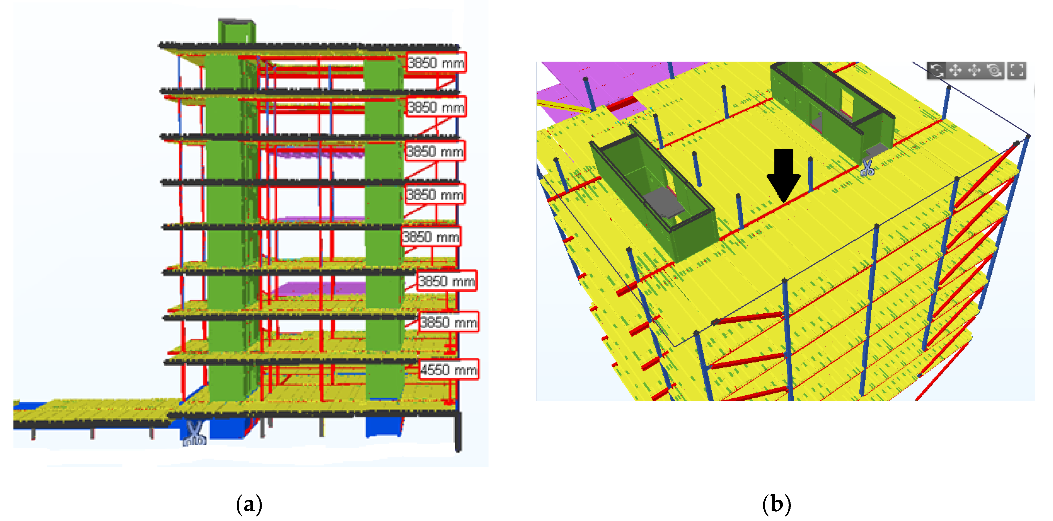
An 8-storey steel-framed commercial building (Figure 2) with an area of almost 5000 square meters was selected for the study to determine the efficiency of composite beam application [22]. The total height of the building is 31.5 m (the height of the first floor is 4.55 m, the height of other floors is 3.85 m), the width is 24 m, and the length is 25 m. The height of the concrete floor slabs is 200 mm. Hollow-core concrete slabs of 9.8 m in length are rested on one side of the beam shelf and hollow-core concrete slabs of 6.8 m in length are rested on the other side of the beam shelf. The selected 5.4-m-long beam is located in the middle of the seventh floor of the building. In the first case, the frame of the building consisted of composite columns, composite beams and hollow-core concrete slabs (Section 3.1). In the second case, the frame of the building consisted of composite columns, reinforced concrete beams and hollow-core concrete slabs (Section 3.2). The floor structure can be composed either of precast units, hollow-core concrete slabs with or without a concrete topping [23], or of deeply profiled steel decking and cast-in-place concrete [24]. Composite beams selected for the researched structure have shelves on both sides, on which hollow-core slabs are rested. After the installation, the inside of the beam (Deltabeam), gaps between the beams (Thorbeam, asymmetric slim floor beam, slim floor beam), and hollow-core slabs are filled completely with concrete mix on site. The concrete mix used to fill the beams and hollow-core slabs makes a composite structure after the setting of concrete and acquires the necessary strength. Hollow-core concrete slabs used in construction reduce the need of formwork. The cavities in hollow-core slabs reduce the amount of concrete used, and, consequently, reduce the weight of the concrete floor slab. All of the aforementioned factors make the construction lighter and reduce the foundation dimensions necessary to bear the loads. A reinforced concrete beam chosen for comparison also has two shelves, on which a hollow-core slab is rested.
All the composite beams researched (Deltabeam, Thorbeam, asymmetric slim floor beam and slim floor beam) with composite columns in the researched building are joined by bolts, whereas a reinforced concrete beam is joined to composite columns using a PCs® (column cantilever) and a PC® (beam pads) cantilever joining system. During the installation of hollow-core slabs, all loads are transferred to the beam through beam shelves. Support is vital in order to protect the beams from rotating in support points. Both beams and hollow-core slabs are installed with the help of a crane using additional tools.
The following software programmes were used for composite beam design in this research (Table 3): SCIA Engineer [25] was used for alternative A1, Peikko Designer [26] was used for alternative A2, and a designing tool, CoSFB v1.6, developed by ArcelorMittal was also used [27].
A software programme of LLC Sistela was used for the estimation of construction works. The cost price also included additional materials, i.e., concrete mix required for concreting works, equipment necessary for the installation and labour costs for carrying out the above-mentioned works.
The rational option of the four alternative solutions (A1—A4) analysed according to nine rating criteria was determined using the Technique for Order Preference by Similarity to an Ideal Solution (TOPSIS) method. This multi-criteria decision making method was chosen due to the concept that the selected alternative should have the shortest distance from the positive ideal solution and the longest distance from the negative-ideal solution [28]. The selected values of criteria (K1—K9) that describe the options of the selected types of composite beams are presented in the initial Matrix P of alternative solutions (Table 6).

3. Results and Discussion

3.1. Comparison of Composite Beams

Firstly, the significance of the evaluation criteria was determined by means of the questionnaire. The priority ranking and importance of the criteria resulting from the survey is given in Table 4. As the questions were abstract, employees holding different positions in a company were asked to fill in the questionnaire. In total, 11 respondents participated in the survey: six design engineers (55% of all the respondents); three managers (27% of the respondents); other employees—a company manager and a project manager (18% of the respondents). All respondents were acquainted with the four composite beams analysed in the questionnaire. The most significant criteria for design engineers were the bearing capacity and fire resistance. Managers placed importance on the installation time and complexity of the installation. A company manager and a project manager considered the beam’s price and its installation costs to be the most relevant.
Secondly, the respondents were also asked to answer the questions given in Section 2. The analysis of the questionnaire items showed that the respondents attributed the lowest cost to the composite Deltabeam, whereas the composite Slim floor beam was the most expensive (Table 5). According to the respondents, it would take the shortest time to install a composite Deltabeam, whereas a slim floor beam would take the longest time to install. The respondents considered the composite Deltabeam to have the biggest bearing capacity, whereas the asymmetric slim floor beam was seen to have the lowest capacity. The calculation of the points given by the respondents produced the following results: Deltabeam received 160 points, Thorbeam got 144 points, asymmetric slim floor beam got 129 points, and slim floor beam got 111 points. The beam that was valued the highest is considered to be the most rational option from the compared beam alternatives. The respondents regarded the cost of a composite beam to be the most essential criterion.
The rational option was found by means of the TOPSIS method. The initial Matrix P of alternative solutions with criteria optima (Max or Min) and the best value (x*j) are presented in Table 5.
The normalized Matrix P calculated from the Equation (1) is presented in Table 6. The data in the initial matrix P are expressed in different units of measurement and thus cannot be compared. Therefore, the initial Matrix P must be normalised to obtain non-dimensional values.
x i j = x i j i = 1 j x i j 2 ,   i = 1 , m ; j = 1 , n
Here: xiji—line, and j—column of Matrix.
After the normalization of the initial Matrix P, a weighted normalized Matrix P* of alternative solutions is created (Table 7). To this end, the normalized Matrix P is multiplied by the vector of criteria importance (see q1–q9 above) according to Equation (2):
P * = [ P ] × [ q ]
The best case a+ (the best value) and the worst case a (the worst value) are found from Equations (3) and (4) accordingly:
a + = { [ ( m a x i x i j / j J ) , ( m i n j x i j / j J ˙ ) ] / i = 1 , m ¯ } = { a 1 + ; a 2 + ; a 3 + }
a = { [ ( m i n i x i j / j J ) , ( m a x j x i j / j J ˙ ) ] / i = 1 , m ¯ } = { a 1 ; a 2 ; a 3 }
Distances between the real option ai and the best case a+, as well as between the real option ai and the worst case a are computed from Equations (5) and (6):
L i + = j = 1 n | a i j a j + | ,   i = 1 , m ¯
L i = j = 1 n | a i j a j | ,   i = 1 , m ¯
Then, criterion Kbit, showing the relative proximity of the compared alternatives to the ideal alternative, is calculated. The calculated value of criterion Kbit is used to prioritise the alternatives compared. In our case, the alternative with the highest Kbit value is the best. Finally, the efficiency value Ni of the alternatives compared is calculated from Equation (7):
K b i t = L i L i + + L i ,   i = 1 , m ¯
The computation results are presented in Table 8.
Composite beam A2 as slim floor structure evaluated using the TOPSIS method and using nine evaluation criteria was found to be the most rational alternative for composite beams in the steel-frame of an eight-storey high-rise commercial residential building (efficiency value (Ni) ≈ 100%). Deltabeam stands out from the other composite beams according to the best value of evaluation criteria: initial preparation on site (K2), installation time (K3), labour costs (K5), fire resistance (K6), load bearing capacity (K7) and versatility beam (K8). Alternative A2, namely the Thorbeam with efficiency value (Ni) ≈ 79.65%, ranked second. Alternative A4, the asymmetric slim floor beam with efficiency value (Ni) ≈ 70.97% ranked third, and alternative A3, the slim floor beam with efficiency value (Ni) ≈ 37.16% ranked fourth. The method described above can be used to find the optimum solution of composite beams for an eight-storey high-rise commercial building according to the selected criteria.

3.2. Comparison of Composite Beams to Reinforced Concrete Beams

The application possibilities and the main advantages of composite beams as compared to conventional reinforced concrete beams were also analysed. Such beams are widely applied on construction sites in multi-storey buildings in Lithuania. The alternatives were evaluated according to the following rating criteria: the calculated values of beam cost including installation (C1), beam self-weight (C2), and fire resistance (C3). The comparison of cost, self-weight, and fire resistance of the selected beams is summarized in Table 9.
The cost of materials including installation were compared based on construction market prices in Lithuania. The costs of material, welding and installation costs, excluding anti-corrosion resistant painting and fire resistant-painting, were calculated from the economical aspect. According to the calculations, the cost of sheet steel is 0.62 Eur/kg, and the fully burdened labour rate is 25 Eur/hour. The accepted norm for Thorbeam and Deltabeam installation and welding is 5.1 h, whereas the installation time of slim floor beams and asymmetric slim floor beams is 2.55 h. The linear weight of every beam and the total weight were evaluated in calculating the cost of the beam. According to Kravana and Šilih [21], the economic comparison between beam and trusses was made based on the following criteria: self-manufacturing costs of material, sheet-iron cutting, welding, anti-corrosion resistant painting, fire resistant-painting, paneling and erection costs.
Composite beams without additional fire resistance chosen for the research have a rather high fire resistance duration: composite Deltabeam up to 180 min. [29], composite slim floor beam up to 90 min. [30], asymmetric slim floor beam up to 90 min. [30], and composite Thorbeam up to 60 min. [31]. The fire resistance duration of reinforced concrete beams used for the comparison is up to 90 min. [32] when the thickness of the protective concrete layer is up to 55 mm.
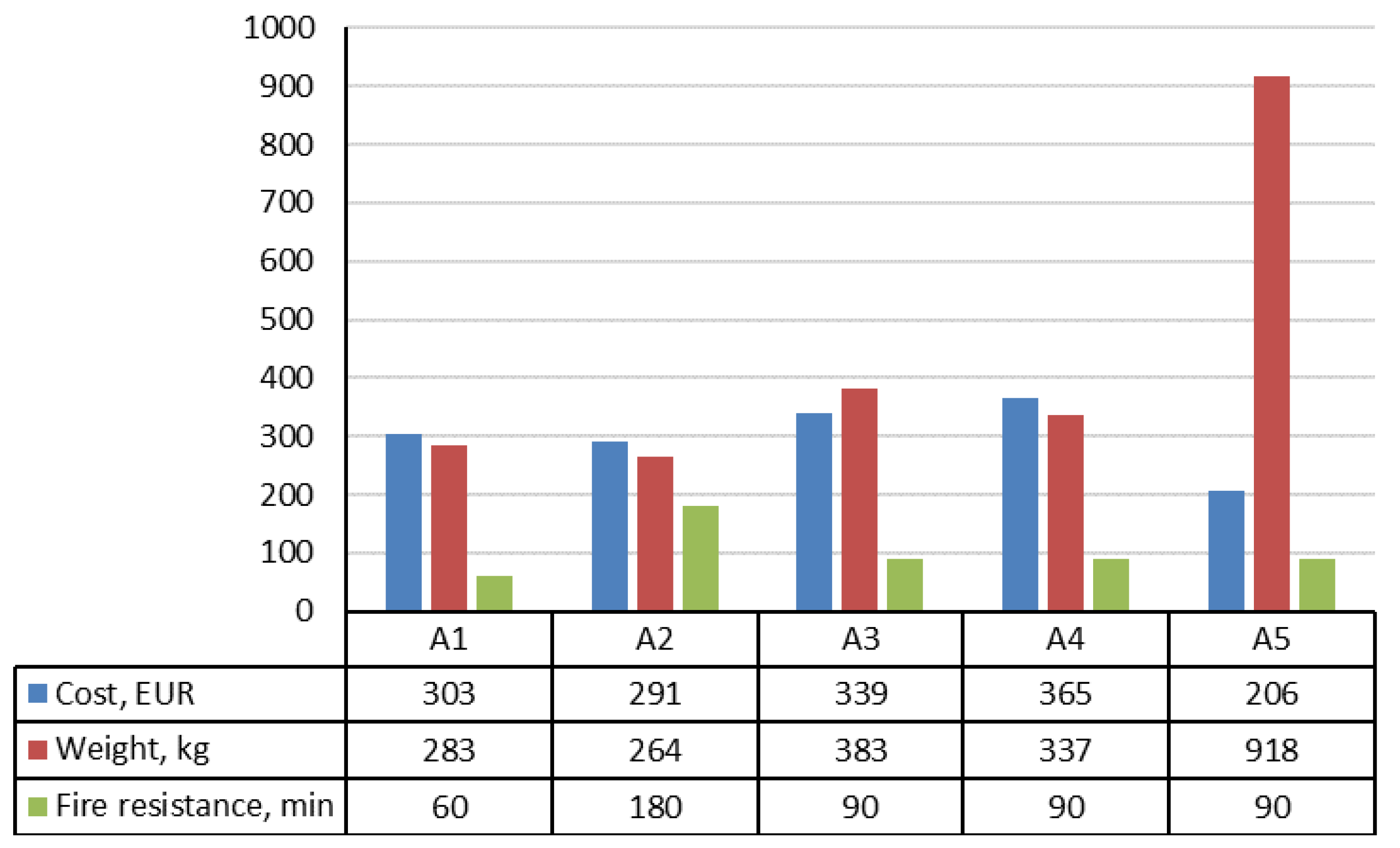
The comparison of composite beams and reinforced concrete beam according to the cost, self-weight and fire resistance is presented in Figure 3. From Figure 3, we can see that it is practical to use Deltabeams for a slim floor structure in a multi-storey building due to the lowest cost of the beam including installation, the lowest self-weight and the highest fire resistance compared to the researched composite beams. However, Deltabeams are 1.4 times more expensive than reinforced concrete beams.
The priority ranking by the lowest cost of beams is as follows: reinforced concrete beam (A5), Deltabeam (A2), Thorbeam (A1), slim floor beam (A3) and asymmetric slim floor beam (A4). The fact that a reinforced concrete beam is cheaper than a composite beam puts it at an advantage. However, according to the authors of [33], the cost is not practical due to precast concrete, delivery and storing, compared to the composite beam. Slim floor structures generate less waste as only prefabricated elements have to be installed on the construction site. Beams can be lifted and moved using ordinary lifting equipment, cranes or forklifts. Fast installation of composite beams reduces crane or forklift operating costs.
The priority ranking by the lowest self-weight of beams is as follows: Deltabeam (A2), Thorbeam (A1), asymmetric slim floor beam (A4), slim floor beam (A3) and reinforced concrete beam (A5). The weight of the beam depends on the bearing capacity. In this research based on the selected multi-storey building (Figure 2), temporary, permanent and variable loads were equal for all types of beams (Table 3). A specific amount of materials is used to manufacture beams referring to the loads of concrete floor slabs. The self-weight of reinforced concrete beams is not practical in terms of transportation and storage of the beams on site as well as installation compared to composite beams. Composite beams can be stored on the erected floor slab of the building during construction. A composite beam with lower self-weight is easier and safer to install on the construction site. It requires a lower capacity crane. The weight of a composite beam is not sufficient to stabilize the frame during the installation of hollow-core slabs, therefore, all beams must be fixed prior to the installation of slabs.
According to priority ranking, Deltabeam (A2) has the highest fire resistance, slim floor beam (A3), asymmetric slim floor (A4) and reinforced concrete beams (A5) have the same fire resistance rating, and Thorbeam (A1) has the lowest fire resistance (Table 9). Asymmetric slim floor beam can achieve a 60 min fire resistance without any additional measures, provided the moment-resistant beam-to-column connection is designed reliably [34]. The composite slim floor beam can be used without any additional measures if the fire load density is less than 1100 MJ/m2, which is rarely exceeded in office and residential buildings. Thermal predictions for protected slim floors show that temperatures in the steel section remain within 400 °C for 60 min of fire exposure [35]. Lower temperatures in the steel part of protected slim floor improve its fire resistance as the protected slim floors offer a fire resistance of more than 120 min. Slim floor systems with symmetric and asymmetric beam cross-sections subjected to fire offer very significant potential advantages compared to conventional composite floors [36].
The height of the selected eight-storey commercial building with the slim floor system applied would be 31.5 m (Figure 2). If reinforced concrete beams are chosen, in order to maintain the same height of the premises, the height of the building would increase by approximately 0.8 m. In this case, the application of the slim floor system would save about 2.5% of the building height, which would make about 500 cubic meters. It is known that slim floor systems make it possible to reduce the floor-to-floor height. Thus, buildings with slim floor systems require less finishing materials due to the smaller volume of the building and would have lower heating and air conditioning costs. The saved space between storeys reduces the total need for vertical elements and constructions, e.g., columns, walls, finishing, elevators, stairs, various channels and pipelines. Engineering networks are installed directly on the slim floor structure without additional bypasses. It contributes to sustainable development. In limited city areas for new constructions, the floor-to-floor height is a significant factor in residential buildings [23].
In the future, extra evaluation criteria relating to beam transportation cost, crane operating cost and storage possibility on site could be included in the proposed algorithm when comparing a composite beam to a reinforced concrete beam. For steel construction manufacturing, extra assessment criteria that may support the reduction in the environmental footprint could be included in the algorithm when comparing different types of composite beams. In a circular economy, materials should be recycled at the end of the product lifecycle. The life cycle assessment in the design stage of composite beams analyses the environmental footprint of the building in the construction and operations phases. Composite beams, which are made from recycled steel, have lower CO2 emission compared to standard steel beams. The environmental impacts are presented in composite beam manufacturers’ environmental product declarations (EPD), for example Deltabeam Green EPD. Such beams contribute to sustainable development.

4. Conclusions

The efficiency of composite beam application in steel-framed multi-storey buildings is solved by means of the algorithm proposed in the study, which delivers efficiency rating criteria of compared beams and reveals effective solutions of composite beams. The algorithm was developed by using a survey questionnaire to obtain the significance of the rating criteria selected and the order of the importance of ranking criteria. The survey questionnaire was also used to obtain the most rational option from the compared beam alternatives based on the respondents’ answers to questions. The rational option from the analysed alternative solutions according to the chosen rating criteria was determined using the TOPSIS method. Prior to starting the detailed design works of the building, investors are offered to perform an economic-technical analysis of the alternatives of the building frame. In this way, they can choose a rational solution of the building frame. This analysis could be carried out according to the research algorithm proposed in the study.
According to the results of this study the following main conclusions were drawn:
  • First, from the results of the survey with civil engineers, the following priority ranking and significance of the selected rating criteria was obtained: 14.87%—beam cost (K1); 14.29%—load bearing capacity (K7); 12.67%—installation time (K3); 12.37%—fire resistance (K6); 12.08%—complexity of installation technology (K4); 11.63%—labour costs (K5); 11.49%—initial preparation on site (K2); 11.49%—beam versatility (K8) and 0.88%—availability of beams (K9). Second, the following scoring of alternatives was obtained from respondents’ answers to questions: alternative A2 received 160 points, A1 received 144 points, A4 received 129 points, A3 received 111 points. Deltabeam (A2) is considered to be the most rational option from the compared beam alternatives. The respondents regarded the cost of a composite beam to be the most essential criterion.
  • The analysis done using the TOPSIS method and nine rating criteria (K1—K9) showed that the composite Deltabeam is the most rational alternative for a Slim floor structure in a steel-framed eight-storey high-rise commercial residential building (efficiency value (Ni) ≈ 100%). The efficiency value of Thorbeam (A2) was approx. 79.65%, of asymmetric slim floor beam (A4) approx. 70.97%, and of slim floor beam (A3) approx. 37.16%. Deltabeam stands out from the other composite beams for the best value of evaluation criteria: initial preparation on site (K2), installation time (K3), labour costs (K5), fire resistance (K6), load bearing capacity (K7) and beam versatility (K8).
  • The application of Deltabeam as a slim floor structure in a multi-storey building is practical due to the lowest cost of the beam including installation, self-weight and the highest fire resistance compared to the other composite beams researched. Deltabeams are 1.4 times more expensive than reinforced concrete beams, including installation costs, but they save about 2.5% of the building’s height compared to reinforced concrete beams. The height of the selected eight-storey building would increase by approximately 0.8 m if reinforced concrete beams are applied. This should be taken into account when economic-technical analysis of the building frame alternatives is conducted.

Author Contributions

Conceptualization, T.K. and M.D.; methodology, T.K.; software, T.K.; validation, T.K.; formal analysis, J.M.; investigation, T.K.; resources, J.M.; data curation, T.K. and M.D.; writing—original draft preparation, T.K. and M.D.; writing—review and editing, T.K., M.D. and J.M.; visualization, T.K.; supervision, M.D. All authors have read and agreed to the published version of the manuscript.

Funding

This research received no external funding.

Acknowledgments

The authors would like to express their gratitude to respondents who participated in the survey.

Conflicts of Interest

The authors declare no conflict of interest.

References

  1. Chung, K. Composite beams and floor systems fully integrated with building services. Prog. Struct. Eng. Mater. 2002, 4, 169–178. [Google Scholar] [CrossRef]
  2. Lawson, R.M.; Bode, H.; Brekelmans, J.W.P.M.; Wrigh, P.J.; Mullett, D.L. ‘Slimflor’ and ‘Slimdek’ construction: European developments. Struct. Eng. 1999, 77, 22–30. [Google Scholar]
  3. Limazie, T.; Chen, S. Numerical procedure for nonlinear behavior analysis of composite slim floor beams. J. Constr. Steel Res. 2015, 106, 209–219. [Google Scholar] [CrossRef]
  4. Bratina, S.; Saje, M.; Planinc, I. On materially and geometrically non-linear analysis of reinforced concrete planar frames. Int. J. Solids Struct. 2004, 41, 7181–7207. [Google Scholar] [CrossRef]
  5. Wang, Y.; Yang, L.; Shi, Y.; Zhang, R. Loading capacity of composite slim frame beams. J. Constr. Steel Res. 2009, 65, 650–661. [Google Scholar] [CrossRef]
  6. Dai, X.; Lam, D.; Sheehan, T.; Yang, J.; Zhou, K. Effect of dowel shear connector on performance of slim-floor composite shear beams. J. Constr. Steel Res. 2020, 173, 106243. [Google Scholar] [CrossRef]
  7. Sheehan, T.; Dai, X.; Yang, J.; Zhou, K.; Lam, D. Flexural behaviour of composite slim floor beams. Structures 2019, 21, 22–32. [Google Scholar] [CrossRef] [Green Version]
  8. Baldassino, N.; Roverso, G.; Ranzi, G.; Zandonini, R. Service and Ultimate Behaviour of Slim Floor Beams: An Experimental Study. Structures 2019, 17, 74–86. [Google Scholar] [CrossRef]
  9. Ahmed, I.M.; Tsavdaridis, K.D. The evolution of composite flooring systems: Applications, testing, modelling and eurocode design approaches. J. Constr. Steel Res. 2019, 155, 286–300. [Google Scholar] [CrossRef]
  10. Zeng, J.; Lu, W.; Paavola, J. Ultimate strength of a beam-to-column joint in a composite slim floor frame. J. Constr. Steel Res. 2018, 140, 82–91. [Google Scholar] [CrossRef] [Green Version]
  11. Bailey, C. The behaviour of asymmetric slim floor steel beams in fire. J. Constr. Steel Res. 1999, 50, 235–257. [Google Scholar] [CrossRef]
  12. Ellobody, E. Composite slim floor stainless steel beam construction exposed to different fires. Eng. Struct. 2012, 36, 1–13. [Google Scholar] [CrossRef]
  13. Braun, M.; Zaganelli, D.; Hanus, F.; Obiala, R.; Cajot, L.-G.; Peirce, A. 10.31: Simplified analytical determination of the temperature distribution and the load bearing resistance of slim-floor beams. Ce/Papers 2017, 1, 2780–2789. [Google Scholar] [CrossRef]
  14. Albero, V.; Serra, E.; Espinós, A.; Romero, M.; Hospitaler, A. Innovative solutions for enhancing the fire resistance of slim-floor beams: Thermal experiments. J. Constr. Steel Res. 2020, 165, 105897. [Google Scholar] [CrossRef]
  15. Ahn, J.-K.; Lee, C.-H. Fire behavior and resistance of partially encased and slim-floor composite beams. J. Constr. Steel Res. 2017, 129, 276–285. [Google Scholar] [CrossRef]
  16. Albero, V.; Espinós, A.; Serra, E.; Romero, M.; Hospitaler, A. Numerical study on the flexural behaviour of slim-floor beams with hollow core slabs at elevated temperature. Eng. Struct. 2019, 180, 561–573. [Google Scholar] [CrossRef]
  17. De Nardin, S.; El Debs, A.L.H.D.C. Composite connections in slim-floor system: An experimental study. J. Constr. Steel Res. 2012, 68, 78–88. [Google Scholar] [CrossRef]
  18. Derkowski, W.; Skalski, P. New concept of slim floor with prestressed composite beams. Procedia Eng. 2017, 193, 176–183. [Google Scholar] [CrossRef]
  19. Nadasky, P. Concrete Composite Beams for Slim Floors–Specific Design Features in Scope of Steel Frames Design. Procedia Eng. 2012, 40, 274–279. [Google Scholar] [CrossRef] [Green Version]
  20. Chen, S.; Limazie, T.; Tan, J. Flexural behavior of shallow cellular composite floor beams with innovative shear connections. J. Constr. Steel Res. 2015, 106, 329–346. [Google Scholar] [CrossRef]
  21. Kravanja, S.; Silih, S. Optimization based comparison between composite I beams and composite trusses. J. Constr. Steel Res. 2003, 59, 609–625. [Google Scholar] [CrossRef]
  22. Fortnox. An 8-Storey High-Rise Commercial Building. Available online: https://mpbolagen.se/en/cable-management/references/previous-references/2016-fortnox-vaxjo/ (accessed on 5 February 2018).
  23. Mullet, D.L. Slim Floor Design and Construction; SCI: Ascot, UK, 1992; p. 161. [Google Scholar]
  24. Mullet, D.L.; Lawson, R.M. Slim Floor Construction Using Deep Decking; SCI: Ascot, UK, 1993; p. 166. [Google Scholar]
  25. SCIA. Computer Software SCIA Engineer. Available online: https://www.scia.net/en/software/scia-engineer (accessed on 5 February 2018).
  26. Peikko. Computer Software Peikko Designer. Available online: https://www.peikko.com/design-tools/ (accessed on 5 February 2018).
  27. ArcelorMittal. Computer Software-CoSFB v1.6. Available online: http://sections.arcelormittal.com/download-center/design-software/composite-solutions.html (accessed on 5 February 2018).
  28. Antucheviciene, J.; Zakarevicius, A.; Zavadskas, E.K. Measuring Congruence of Ranking Results Applying Particular MCDM Methods. Information 2011, 22, 319–338. [Google Scholar] [CrossRef]
  29. Peikko. Technical Manual Deltabeam. Available online: https://d76yt12idvq5b.cloudfront.net/file/dl/i/yWebiQ/a0s3skneSuBvHmt1bD-UZA/DELTABEAMLT001TMA.pdf (accessed on 5 February 2018).
  30. ArcelorMittal. Technical Manual–Slim Floor Beam and Asymmetric Slim Floor Beam. Available online: http://sections.arcelormittal.com/fileadmin/redaction/4Library/1Sales_programme_Brochures/SlimFloor/SlimFloor_EN.pdf (accessed on 5 February 2018).
  31. Norwegian Fire Research Laboratory. Resistance to Fire of Thorbeam. Available online: https://www.paroc.com/spps/documentation/SE_FireTestRep_SINTEF_4_en.pdf (accessed on 5 February 2018).
  32. Vilniaus Gelžbetoninių Konstrukcijų Gamykla Nr. 3. Technical Manual Reinforced Concrete Beam. Available online: http://www.gkg3.lt/?page_id=418 (accessed on 5 February 2018).
  33. Daewoo Institute of Construction Technology. Development of Proposed System; Technical Rep. No. DEP-001-2001; DICT: Suwon, Korea, 2001. [Google Scholar]
  34. Mäkeläinen, P.; Ma, Z. Fire resistance of composite slim floor beams. J. Constr. Steel Res. 2000, 54, 345–363. [Google Scholar] [CrossRef]
  35. Alam, N.; Nadjai, A.; Ali, F.; Nadjai, W. Structural response of unprotected and protected slim floors in fire. J. Constr. Steel Res. 2018, 142, 44–54. [Google Scholar] [CrossRef]
  36. Cai, J.; Burgess, I.; Plank, R. Modelling of asymmetric cross-section members for fire conditions. J. Constr. Steel Res. 2002, 58, 389–412. [Google Scholar] [CrossRef]
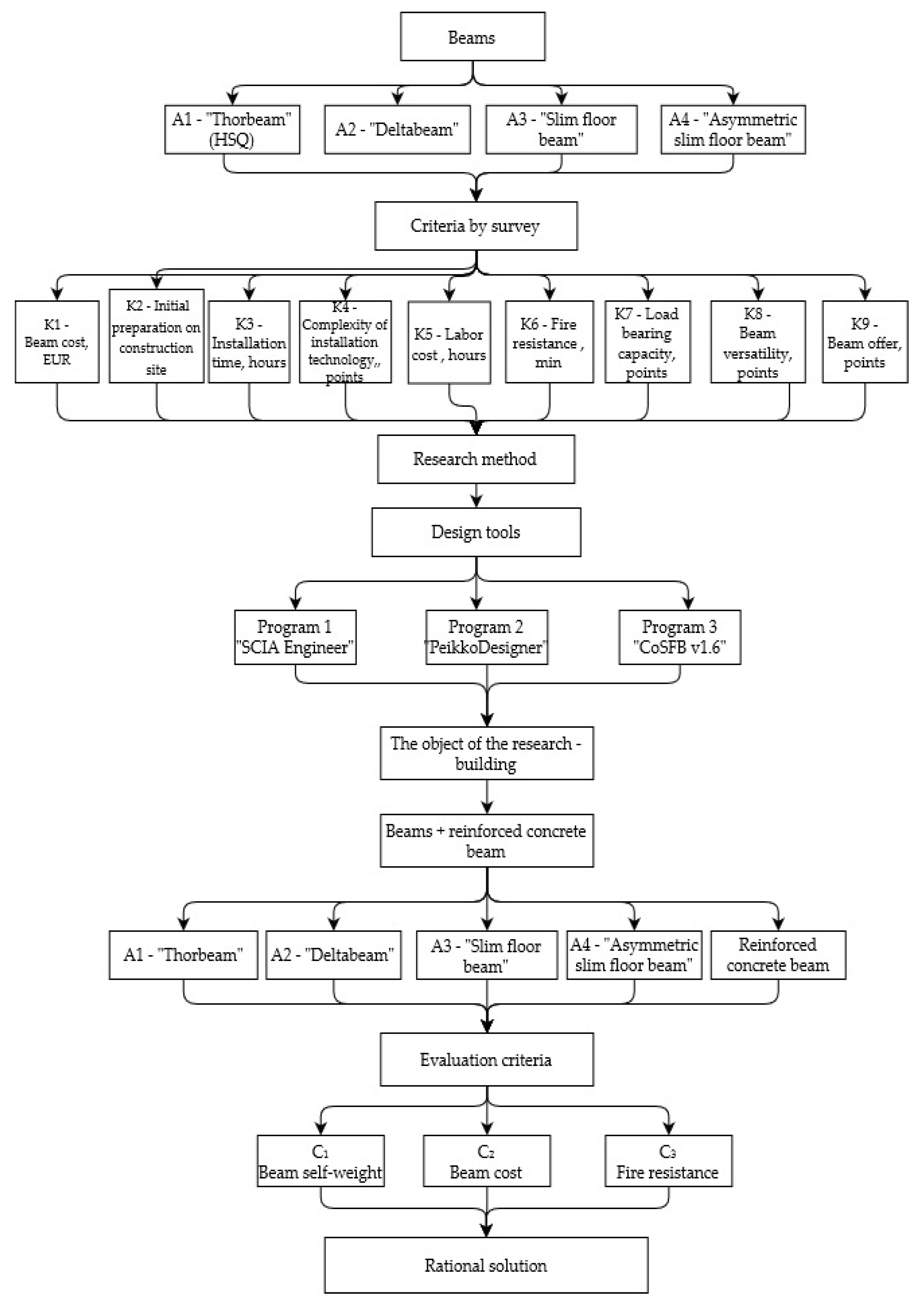
Figure 1. The algorithm of the efficiency of composite beam application in a multi-storey building frame.
Sustainability 12 08328 g001
Figure 2. The view of an 8-storey high-rise commercial building (a) and the selected beam location in the building (b).
Sustainability 12 08328 g002
Figure 3. Comparison of composite beams to reinforced concrete beam.
Sustainability 12 08328 g003
Table 1. Four types of composite beams chosen for the study.
AlternativesDescriptionPrinciple Scheme
A1“Thorbeam” is a thin slab conception created in Scandinavia; it consists of two channel sections welded to a flat plate. Sustainability 12 08328 i001
A2“Deltabeam” is a composite beam system created in Finland; it consists of a steel web section welded to a flat plate. Sustainability 12 08328 i002
A3“Slim floor beam” is a solution invented by the British Construction Institute; it consists of a universal steel column section welded to a steel plate. Sustainability 12 08328 i003
A4“Asymmetric slim floor beam” is also a British invention consisting of an asymmetric hot-rolled steel beam. Sustainability 12 08328 i004
Table 2. Initial information presented to the interviewees of the survey.
No.Evaluation CriteriaOptimization Direction of CriteriaEvaluation in Points
(from 1 to 10)
MinMax
1K1, Beam cost, EUR×
2K2, Initial preparation on site, points×
3K3, Installation time, hours×
4K4, Complexity of installation technology, points×
5K5, Labour costs, hours×
6K6, Fire resistance, min ×
7K7, Load bearing capacity, points ×
8K8, Beam versatility, points ×
9K9, Availability of beams, points ×
Table 3. Calculation scheme and initial data for beam design.
Cross-SectionThe Calculation Scheme is Created According to the Selected ObjectInitial Data for CalculationDesigned Beam
Sustainability 12 08328 i005 Sustainability 12 08328 i006Structure name—beam of 5.4 m in length.
Structure type—single span.
Loads on beam: temporary load—4.2 kN/m, permanent load—26.6 kN/m, variable load—24.9 kN/m.
Structure name—slab (left) of 9.8 m in length, slab (right) of 6.8 m in length.
Structure type—hollow-core concrete slab of 200 mm in height.
Bottom plate—15 mm thickness, webs—8 mm thickness; top plate—25 mm thickness.
Sustainability 12 08328 i007Profile—D20-300.
Sustainability 12 08328 i008 Sustainability 12 08328 i009Main profile—HEB160, bottom plate—10 × 360 mm.
Sustainability 12 08328 i010Main profile—IPE300 O, bottom plate—10 × 360 mm.
Sustainability 12 08328 i011 Sustainability 12 08328 i012
Note: The reinforced concrete beam was not designed. The preliminary measurements of the beam are chosen as per manufacturer’s recommendations.
Table 4. Importance and order of criteria.
No.Evaluation CriteriaOptimization Direction of CriteriaTotal Amount of Points by SurveyImportance of Criteria by SurveyPriority Ranking by Survey
MinMax
1.K1, Beam cost, EUR× 10114.871
2.K2, Initial preparation on site, points× 7811.497
3.K3, Installation time, hours× 8612.673
4.K4, Complexity of installation technology, points× 8212.085
5.K5, Labour costs, hours× 7911.636
6.K6, Fire resistance, min ×8412.374
7.K7, Load bearing capacity, points ×9714.292
8.K8, Beam versatility, points ×669.728
9.K9, Availability of beams, points ×60.889
Total sum679100.00
Table 5. The initial Matrix P of alternative solutions.
CriteriaK1K2K3K4K5K6K7K8K9
Options
A1303310.50221.5060302255
A2291220.30370.90180555235
A3339480.60451.8090444233
A4207530.55501.6590253831
Optimization directionMinMinMinMinMinMaxMaxMaxMax
Best value207220.30220.90180555255
Importance of criteria q, % 14.8711.4912.6712.0811.6312.3714.299.720.88
Table 6. Normalized Matrix P.
CriteriaK1K2K3K4K5K6K7K8K9
Options
A10.5240.3830.4990.2750.4990.2630.3730.2750.693
A20.5030.2720.3000.4630.3000.7880.6830.6500.441
A30.5860.5930.5990.5630.5990.3940.5460.5250.416
A40.3580.6540.5490.6260.5490.3940.3100.4750.391
Table 7. Weighted normalized Matrix P* of alternative solutions.
CriteriaK1K2K3K4K5K6K7K8K9
Options
A10.0780.0440.0630.0330.0580.0320.0530.0270.006
A20.0750.0310.0380.0560.0350.0970.0980.0630.004
A30.0870.0680.0760.0680.0700.0490.0780.0510.004
A40.0530.0750.0700.0760.0640.0490.0440.0460.003
Table 8. The most rational option obtained by means of the TOPSIS method.
Options L i + L i   K b i t Priority Ranking of AlternativesEfficiency Value of Alternatives (Ni), %
A10.0510.0560.524279.65
A20.0390.0750.6571100.00
A30.0910.0290.244437.16
A40.0620.0540.467370.97
Table 9. The comparison of cost, weight and fire resistance of the selected beams.
AlternativesRating Criteria C1—Beam Self-WeightRating Criteria C2—Beam Cost including InstallationRating Criteria C3—Fire Resistance
A1Designed beam is given in Table 3. The sheets are welded together by a4 welding seam, total length of the seam is 5.4 m × 4 = 21.6 m.
The calculated weight of the beam is ~ 283 kg.
Material cost:
283 kg × 0.62 Eur/kg = 175.46 Eur;
Labour costs:
5.1 h × 25 Eur/h = 127.50 Eur;
Cost price of the beam:
175.46 Eur + 127.50 Eur = 302.96 Eur.
The required fire resistance up to 60 min of steel beams with flange thickness up to 15 mm can be achieved by installing Paroc EPS 17 Boards below the flange extending 50 mm beyond the edge on each side of the flange width.
Fire resistance R60.
A2Designed beam is given in Table 3. The calculated weight of the beam ~ 264 kg. Material cost:
264 kg × 0.62 Eur/kg = 163.68 Eur;
Labour costs:
5.1 h × 25 Eur/h = 127.50 Eur;
Cost price of the beam:
163.68 Eur + 127.50 Eur = 291.18 Eur.
A designed number of fire reinforcement is installed inside the beam in a factory. High fire resistance up to R180 is achieved due to fire reinforcement and concrete filling of the beam.
Fire resistance R180.
A3Designed beam is given in Table 3. The calculated weight of the beam ~ 383 kg.Material cost:
382.65 kg × 0.72 Eur/kg = 275.51Eur;
Labour costs:
2.55 h × 25 Eur/h = 63.75 Eur;
Cost price of the beam:
275.51 Eur + 63.75 Eur = 339.26 Eur.
The combination of a beam and a hollow-core slab ensures construction protection corresponding to the requirements up to the R90 fire resistance class. For this reason, additional passive fire protection is not necessary.
Fire resistance R90.
A4Designed beam is given in Table 3. The calculated weight of the beam ~ 337 kg (without cutting the shelf ~ 419 kg). Material cost:
419 kg × 0.72 Eur/kg = 301.68 Eur;
Labour costs:
2.55 h × 25 Eur/h = 63.75 Eur;
Cost price of the beam:
301.68 Eur + 63.75 Eur = 365.43 Eur.
The combination of a beam and a hollow-core slab ensures construction protection corresponding to the requirements up to the R90 fire resistance class. For this reason, additional passive fire protection is not necessary.
Fire resistance R90.
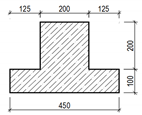
A5The area of the beam cross-section is 0.085 m2; length is 5.4 m; volume is 5.4 × 0.085= 0.459 m3; weight is 2000 × 0.459 = 918 kg (reinforced concrete density 2000 kg/m3).As reinforced concrete manufacturers claim, the cost price of the beams of such type is about 450 Eur/m3. The cost of the researched reinforced concrete beam is—450 Eur/m3 × 0.459 m3 = 206.55 Eur.Fire resistance class determined by the manufacturer is up to R90 when the protective concrete layer’s thickness is 55 mm.
Fire resistance R90.