Article

Collaborative Scheduling of On-Site and Off-Site Operations in Prefabrication

1
Department of Civil Engineering and Architecture, Wuhan University of Technology, Wuhan 430070, China
2
Department of Art and Science, University of Toronto, Toronto, ON M5S 1A1, Canada
3
Department of Civil Engineering, Monash University, Melbourne, VIC 3800, Australia
*
Author to whom correspondence should be addressed.
Sustainability 2020, 12(21), 9266; https://doi.org/10.3390/su12219266
Submission received: 15 September 2020 / Revised: 15 October 2020 / Accepted: 6 November 2020 / Published: 8 November 2020
(This article belongs to the Section Sustainable Engineering and Science)

Abstract

:
As a kind of sustainable technology, prefabricated construction has increasingly gained momentum internationally due to its numerous benefits that include, but are not limited to, safe construction, waste minimization, quality improvement, and productivity enhancement. However, productivity in this domain is reliant on the efficiency of both on-site and off-site operations. On this basis, focusing on collaborative scheduling mechanisms, the current paper develops a static scheduling model and a dynamic scheduling model in prefabricated construction, and uses a simulated annealing algorithm (SA) to settle the optimization of operation planning considering delays by risks. The developed models are validated using data from a construction project with multiple suppliers of prefabricated elements. This study contributes to the body of knowledge in prefabricated construction management by streamlining collaborative scheduling in prefabrication. The established models provide construction managers with decision support systems with the aims of minimizing delays and related cost overruns.

1. Introduction

Prefabrication is a kind of innovative construction approach that includes off-site manufacture and on-site installation. It is gaining more and more attention in the construction industry due to the benefits of decreasing construction time, improving architecture quality, enhancing utilization efficiency of materials, and worker safety, as well as limiting environmental impacts during the construction process [1,2,3]. Thus, it plays an important role in supporting the sustainability of the construction industry [4].
Considering the importance of prefabrication, many researchers have investigated scheduling of processes in this sector. The critical path method is a traditional and common technique used for construction scheduling. It is a helpful tool that can be used along with other techniques, such as line of balance [5], Monte-Carlo simulation [6], and artificial bee colony algorithms [7]. Heuristic methods have been applied in scheduling multiple construction projects [8,9]. Furthermore, integer goal programming can be utilized to generate schedules [10]. Due to the efficiency of heuristic methods in solving complex scheduling problems, many studies used heuristic algorithms to minimize the cost of component delivery management in off-site construction [11,12,13]. However, previous studies are often limited in scope by only covering either off-site manufacture or on-site assembly. Furthermore, studies on how to operationally deal with schedule delays in prefabricated construction are sparse.
To address the gap, this paper establishes a constrained optimization model to generate initial schedules based on minimum cost. Subsequently, a dynamic model is developed to address the inherent resultant delays in construction using a collaborative scheduling workflow. Then, a heuristic-based simulated annealing algorithm is applied to solve the two models. To validate the modeling, an off-site construction project in Wuhan, China serves as the test bed. The multistory project has a gross floor area of 18,590 m2 with 22 floors. The prefabricated building elements supplied by multiple suppliers are used to accelerate construction. The proposed methodology for collaborative scheduling of on-site and off-site operations resulted in significant time and cost savings in the case project.
This paper is structured as follows. Following this introductory part, a literature review is provided by conducting a search of the relevant literature. Section 3 proposes the research methodology applied in this analysis. Section 4 establishes the initial static scheduling model and describes the assumptions, formulation, and solution methods. Section 5 elaborates on the dynamic scheduling model in the presence of resultant delays. Section 6 validates the modeling approach using case study data. Finally, Section 7 draws conclusions and specifies opportunities for future research.

2. Literature Review

Prefabrication research has been one of the mainstreams within the construction literature. Prefabrication includes related processes, such as off-site manufacture, transportation, and on-site assembly. Researchers have focused on scheduling in order to improve the productivity of prefabrication [14]. Arashpour et al. [15] selected a multi-supplier configuration to optimize prefabrication supply with dynamic levels of investment in process integration. Combining the approach of system dynamics and discrete event simulation, a hybrid dynamic model was proposed to analyze the impact of risk variables on the schedule performance of prefabrication [16]. Other papers also studied the impact of risk factors related to the schedule of prefabricated construction without solutions of schedule delay [17,18]. A platform based on a radio frequency identification device (RFID) and building information modeling (BIM) was developed to help alleviate delay problems during the schedule process of prefabrication housing in Hong Kong [19]. The paper proposed a intelligentized platform solution from a strategic aspect.
Risks affect construction projects and lead to delays of the planned schedule [20,21,22]. To improve schedule robustness in a risky environment, two kinds of optimization strategies were proposed, which included improving the stability of the schedule plan and the robustness of solutions reacting to risk delays [23]. Comprised of construction duration risk assessment and time buffer allocation, a proactive methodology for schedule reliability was studied [24]. Referring to the above literature, this study adopts time buffer allocation as the first step of collaborative scheduling resistant to risk disruptions. Several papers studied the stable pre-schedule subject to risk disruptions in the job shop area [25,26]. An integrated methodology was developed to proactively create a stable schedule against risk disruptions for on-site projects [27]. However, there is still a gap in the aspect of operational solutions for addressing schedule delays by integrating off-site and on-site workflows. This research establishes collaborative scheduling models to optimize time and cost management in prefabricated multi-floor buildings.
The subject of scheduling is a kind of combinatorial problem consisting of minimizing the time, optimizing consumption of resources, and dealing with uncertainties. It is proved that the heuristic method is efficient in solving problems referring to combinatorial aims. Heuristic methods include constructive algorithms (genetic algorithm) and iterative algorithms (simulated annealing algorithm) [28]. A number of researchers applied heuristic methods, such as a genetic algorithm (GA), and simulated annealing to optimize scheduling. Combining integer goal programming to generate schedules and a simulation model to test heuristic-based rules, the scheduling problem of a construction company undertaking multiple projects constrained by multiple resources was presented [10]. Yang et al. [13] proposed a flow shop scheduling model involving multiple production lines for precast production, in which a GA was applied to mitigate the changeover of molds during production. A simulated annealing (SA) algorithm is a kind of iterative algorithm that aims to find an optimal configuration [28]. Applying SA, a study proposed a methodology to design reinforced concrete building frames, aiming to achieve the optimization of four functions, namely cost, constructability, sustainability, and safety [29]. Considering construction-site layout as a discrete combinatorial optimization problem, Yeh [30] integrated SA and the Hopfield neural network to implement the model. Another study proposed a mathematical model based on SA to optimize the planning of tower cranes in terms of number, type, location, service period, and height ranking, aiming to minimize the total cost within limited daily working time [31]. Combined with BIM, SA was also applied in tunnel construction to develop a methodology to predict varying ground conditions and evaluate risks in excavation costs and durations [32].
Leung et al. [33] presented the shortcoming of GAs—pre-mature convergence—which is the phenomenon of the population becoming homogeneous after the worst members are discarded, while SA was proposed to help prevent being trapped in pre-mature convergence. Another paper compared GAs with SA and proved that SA was more efficient in optimizing time–cost trade-offs in construction management [34]. Therefore, this study applies SA to solve the models.

3. Methodology

3.1. Modeling Framework

This study considers multiple manufacturing plants (A, B) providing required components for on-site installation zones (Z) (see Figure 1). Operations in each zone include a series of activities ( j = 1 , 2 J ). The scheduling model is developed based on the following assumptions:
  • The resources used in operations are regarded as renewable. For instance, labor and equipment can be seized and released more than once by different activities. The overall amount of resources cannot exceed the maximum availability level (R).
  • On-site and off-site operations are undertaken with respect to work flows and after completion of predecessors.
  • The starting times of on-site installations are closely related to finishing times of manufacturing operations. To maintain the continuity of operations, on-site installations are initiated by off-site manufacture completions.
Relationships amongst on-site and off-site operations are shown in Figure 1. The construction schedule for a building with N floors has been broken down to N time cycles of off-site manufacture and on-site installation. Activities highlighted by a green-framed box refer to one job cycle, for instance, cycle n (hereafter referred to as Cyn for simplicity). The operations of A n , B n , and Z n constitute the construction of the nth floor. The three work zones (A, B, and Z) are set on the vertical axis. The horizontal axis stands for time along with the construction process, indicated by t (t = 0,1,2… T N ). The construction process starts at ST and ends at SF. The straight line arrow indicates prefabricated products transported from the manufacture zone to the assembly zone. The dashed line arrow draws the ordering process from the assembly zone to the manufacture zone. The rectangle Z n represents the assembly operation of the nth floor taking a period of time from T n 1 to T n . The rectangles A n + 1 and B n + 1 present the manufacture operation producing the required components for installation operation ( Z n + 1 ). Components produced by multiple manufacturers must arrive at the installation zone ( Z n + 1 ) during the interval of Δ t (time window—TW), or else there will be a storage cost due to early arrivals or a penalty cost due to late arrivals.

3.2. Scheduling Issues

The scheduling process in Figure 1 shows that the schedule plan integrates operations located in three different spaces. Furthermore, the working time of different spaces is demanded to be continuous. The challenge of scheduling in prefabrication derives from the separate locations and managers of off-site and on-site operations, as well as strict supplying time. This paper analyzes the collaborative scheduling issues in the view of the general project contractor in the mode of Engineering Procurement Construction (EPC). Thus, the costs related to on-site activities and off-site activities are both considered in the established models. The final aim of the established models is to achieve the minimum total cost and a relevant scheduling plan within certain limitations.
The collaborative scheduling of prefabricated processes has yet to address the following issues:
  • Real-time limitations in terms of resource availability, cost, and time along with both off-site manufacturing and on-site assembly processes.
  • Large sizes of prefabricated panels and modules create spatial constraints for both off-site and on-site inventories.
Risk events always generate delays in the planned schedule. Furthermore, delays can transfer along with the processes among off-site and on-site spaces. The static scheduling model established in Section 4 focuses on the first two issues. The function for on-site installations aims to calculate the minimum cost of TW management and resource consumption. TW management cost indicates the fee of managing large-size prefabricated components on-site. It is assumed that a linear relation exists between associated costs of TW and its duration because the management fee per day is set as a constant value. The time span of TW is directly proportional to that of the installation operations.
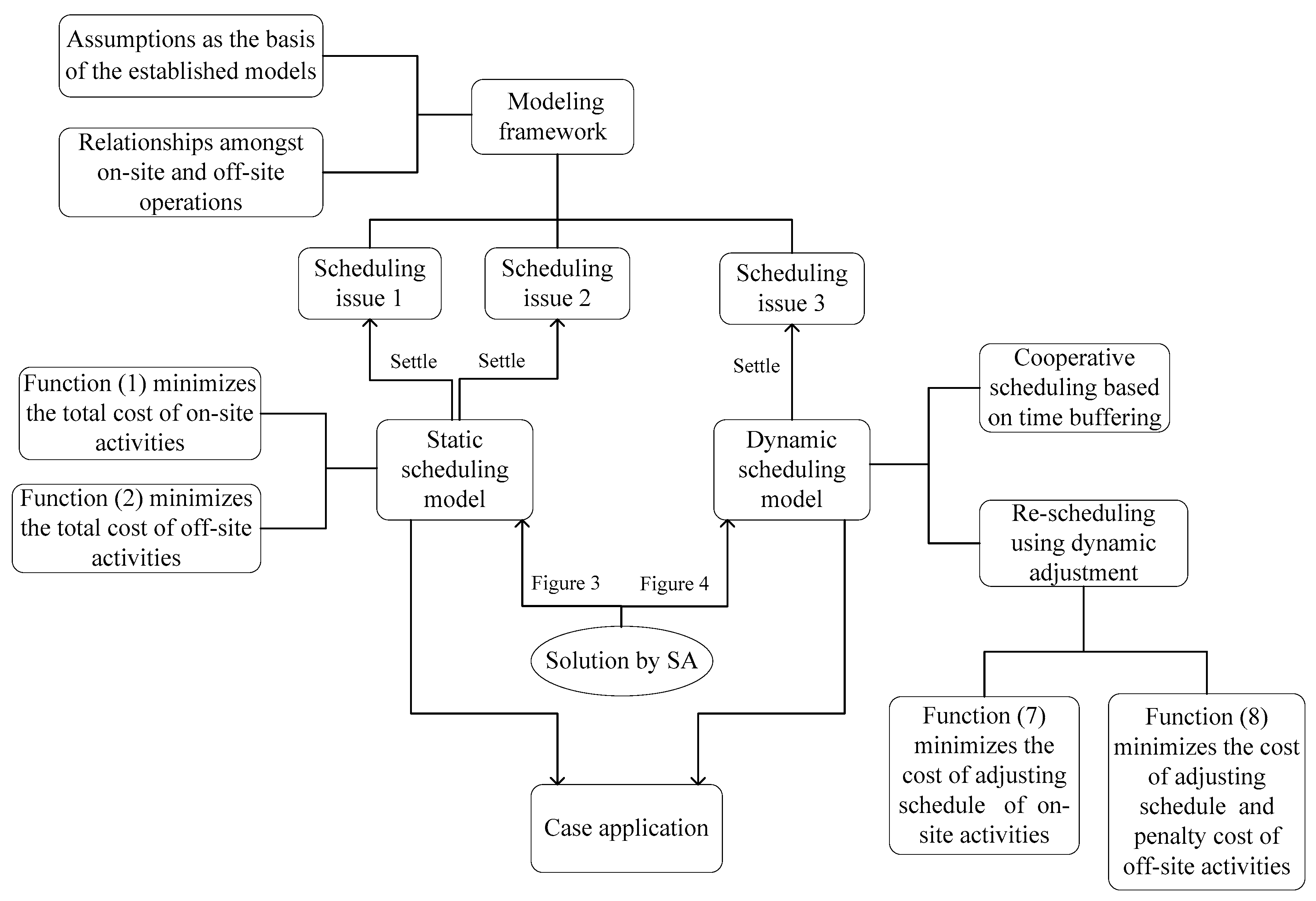
The dynamic scheduling model in Section 5 is proposed to address the third issue. Firstly, time buffers are allocated to enhance the schedule’s robustness to risk events. In the second stage, collaborative rescheduling is undertaken using dynamic adjustments.
Figure 2 draws the flowchart of this research methodology.

4. Static Scheduling Model

4.1. Static Scheduling Model Development

Given that the prefabrication can be completed over N cycles (Figure 1), each cycle contains certain activities ( j = 1 , 2 J ) in the off-site manufacture and on-site installation domains. The symbols and notations used for the modeling purpose are listed in Table 1.
Equation (1) minimizes the total cost of TW management and resource consumption relevant to on-site installations.
min P 0 = k = 1 K max ( t = s 0 j c o j 1 r o j k ) λ o k + Δ t × w
subject to:
s 0 h + d 0 h s 0 j , h Y 0 h , j
j A 0 t r 0 j k R 0 k , k , t
D 0 D
Δ t = μ D 0 , μ > 0
In Equation (1), max ( t = s 0 j c 0 j 1 r 0 j k ) computes the maximum amount of k concurrently required by on-site activities over a certain period. Summation is carried out when multiple activities consume the same kind of resource during the same period. Renewable resources can be used repeatedly for each activity, and the maximum consumption quantity is bound to the availability level. Constraint (2) enforces precedence requirements. Constraint (3) represents the balance of renewable resources. Constraint (4) maintains the total project duration. Constraint (5) imposes the linear relation between the duration of TW and on-site installation operations. The value of μ is set according to the actual project conditions.
Function (6) minimizes the total cost related to off-site manufacturing.
min P i = α max ( T n a c i J , 0 ) + β max ( c i J T n b , 0 ) +   k = 1 K max ( t = s i j c i j 1 r i j k ) λ i k   ,
subject to:
s i h + d i h s i j , h Y i h , j
j A i t r i j k R i k , k , t
T n b = T n ,   T n a = T n b Δ t
i = 1, 2,
wherein k = 1 K max ( t = s i j c i j 1 r i j k ) λ i k calculates the maximum amount of resources required by activities in off-site manufacturing. Constraints (7) and (8) depict restrictions in line with Function (2) and Function (3), respectively. Constraint (9) locates the range of TW in cycle n. Constraint (10) states the two manufacture plants.
From the view point of the general contractor, the optimum weighted combination of the goal values for off-site manufacture and on-site installation is set as the final target of the scheduling. The final objective Function (11) calculates the goal value, which integrates the optimum weighted combination (P) of the cost values for on-site installations ( P 0 ) and off-site manufacturing ( P 1 , P 2 ), where η 1 and η 2 are weight parameters.
P = η 1 P 0 + η 2 i = 1 , 2 P i ,
subject to:
0 η 1 1 , 0 η 2 1 .

4.2. Static Scheduling Model Solution

SA is used to solve the scheduling model. The specific steps are as follows, and are illustrated in Figure 3:
  • Off-site and on-site construction processes are initially scheduled using the critical path method (with maximum resource availability, R 0 max ). Resource quantities required by activities ( j = 1 , 2 J ) are recorded.
  • The following equation will enforce the limited quantity of available resources ( R 0 k ):
    R 0 k = R 0 max ( R 0 max R 0 min ) × ( g / G )
    wherein g is the time of iteration, and G is the maximum number of iterations. The following two steps describe the calculation process in detail:
    Considering restrictions on R 0 k and overall construction duration, the following variables are calculated: minimum P 0 , on-site installation duration D 0 , and the value of Δ t . For Cy1, the end time T 1 = D 0 ; for Cy 2, the end time T 2 = 2 * D 0 , and so on in the rest cycles.
    Based on above calculated values, T n a and T n b can be gained as the arrival time for prefabricated components. Considering the minimum of P i (i = 1, 2) as the optimal goal and the values of T n a and T n b , the initial optimal schedules of off-site manufacturing processes can be obtained.
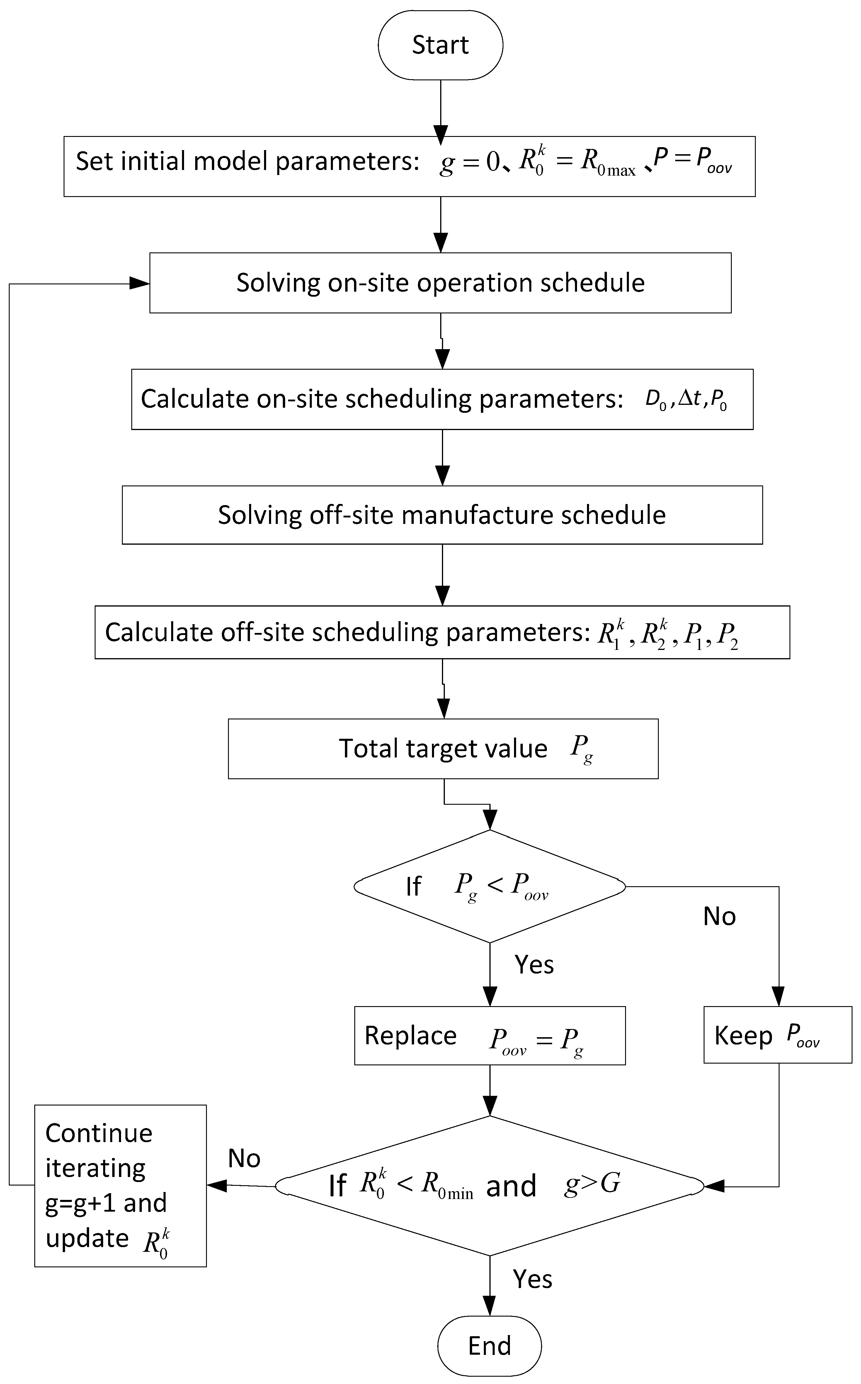
  • Based on the above calculations, the final target value p can be determined by Function (11). During the first iteration, the initial model parameters are set to g = 0, R 0 k = R 0 max , and the calculation results from Function (11) are temporarily set as the overall optimal value ( P o o v ). After finishing the subsequent iteration, the new target value P = P g is compared with P o o v . If the new target value P g is optimal, it will replace the results in the last iteration and set a new P o o v . Simultaneously, the new combination scheduling plan will replace the last one correspondingly. Otherwise, P o o v will be kept, and the results in the recent iteration are discarded.
  • The iterations end when R 0 k < R 0 min and g > G. The most recent value of P o o v is set as the final overall optimal value p, and relative plans are accepted as the optimal schedules for on-site installation S H 0 and off-site manufacturing plants S H i (i = 1, 2), where SH is the starting time series indicated by { s 1 , s 2 , s 3 , s j , s J } .

5. Dynamic Scheduling Model Subject to Risk

This section proposes a collaborative scheduling method addressing delays caused by risks. Unforeseen events such as inclement weather, site accidents, and equipment failure can trigger delays in prefabrication [35]. Due to the existence of time buffers, construction schedules can alleviate delays resulting from delays to a certain extent. This depends on the impact size of risk events and also flexibility in using time buffers. If delays cannot be prevented, collaborative rescheduling is undertaken in the second stage of the proposed scheduling approach using dynamic adjustments.

5.1. Cooperative Scheduling Based on Time Buffering

To improve the stability of project scheduling in the presence of risk disruptions, the time-buffering method is commonly adopted [24,36]. Time buffering can be undertaken in two ways. The first and more intuitive method is to exploit the inherent free float of construction activities. In a similar approach to those of Hoel [37] and He et al. [38], free floats of activities are utilized as the time buffer b i j .
b i j = min ( i , f ) V i f s i f min c i j ,
where V i f indicates the set of successive activities of j in construction zone i.
The second time-buffering method allocates buffers based on the instability weight of activities. After setting the initial scheduling plan, the total float can be decomposed into different ranges and then allocated based on the unreliability of each activity. The factor D B ( j ) determines the degree of priority to allocate to time buffers for an activity j. It can be calculated using Equation (15).
D B ( j ) = I N S ( ϕ j ) m = 1 F F j e m ,
where I N S ( φ j ) is the extent of instability for activity j, determined by the penalty coefficient of predecessor ( φ h ) and successor ( φ f ). That is:
I N S ( φ j ) = φ h / ( φ h + φ f ) , h Y h , f V f ,
where the letter h indicates the preceding activity of j, and f indicates the succeeding activity. Y h is the set of preceding activities of j, and V f is the set of succeeding activities.
m = 1 F F j e m is proposed by Lambrechts [39] to reallocate the buffer value by decrementing benefit according to the free float ( F F j ) of activities in the scheduling plan, in which m varies from 1 to F F j .
At time T, disruptions caused by risks extend the duration of j by Δ E . After allocating time buffers to activities, delays are addressed using one of the following ways:
  • If bij ≥ ΔE, it indicates that the time buffer can eliminate the delay.
  • If bij < ΔE, the delay of ΔEbij will be transferred to the succeeding activities. If buffers of the following activities cannot eliminate the delay, the total duration of work has to be extended. The necessity of rescheduling is proposed to ensure that the cascading effect of the delay can be eliminated in the following cycles.

5.2. Rescheduling Using Dynamic Adjustment

Time buffers of all activities involved in an operation determine the capacity of managing delays. If the maximum delay duration is ε , it can be addressed by rescheduling of on-site and/or off-site operations. Therefore, the following scenarios can be considered:
  • Delays related to on-site operations:
Delays in on-site installation of elements related to the nth floor (cycle n) will change the finishing time of operations into T n = T n + Δ E 1 . In addition, operations on floor n + 1 ( Z n + 1 ) will also be affected, during which rescheduling takes place to offset the delay. Accordingly, the duration of operation Z n + 1 has to be decreased from the original D 0 into D 0 min ( Δ E 1 , ε ) .
  • Delays related to off-site operations:
Output products of operations B n + 1 in off-site manufacturing plants are used in on-site operations of floor n + 1 ( Z n + 1 ); therefore, the delay of B n + 1 will lead to the postponement of Z n + 1 . If delays extend the duration of B n + 1 by Δ E 2 , the period of Z n + 1 will increase by Δ E 2 . When ε Δ E 2 , the original duration of Z n + 1 should be decreased from D 0 into D 0 Δ E 2 , and the following cycles will be processed according to the initial schedule. However, when ε < Δ E 2 , Z n + 1 only partially offsets delays. As a result, the remaining Δ E 2 ε will be pushed into the next cycle.

5.3. Collaborative Scheduling Solution

When delays occur at a point in time, three conditions are possible. Some activities are already finished and, therefore, not affected ( F S i T ), a set of activities are in progress ( U D i T ), or remaining activities have not been started ( F U i T ). The starting times of activities F S i T and U D i T remain aligned with the initial schedule. Rescheduling measures are, therefore, applicable to the activities F U i T .
To minimize costs caused by delays, dynamic scheduling equations are established to achieve the minimum penalty costs for alteration of activities. Given ε < Δ E 1 , dynamic scheduling measures are suggested using Equation (17) as the target function. The cost of adjusting the schedule of operations related to the nth floor ( Z n ) and the optimal duration r e D 0 can be calculated using the following equations:
min Q 0 = j = 0 J φ 0 j | s 0 j s 0 j | ,
subject to:
s 0 j = s 0 j , j F S 0 T U D 0 T
s 0 h + d 0 h s 0 j , h Y 0 h ,   j   F U 0 T
j A 0 t r 0 j k R 0 k , k , t = T , T + 1
In Equation (17), φ 0 j is the penalty coefficient for on-site activity j, and s 0 j is the adjusted starting time of activity j after the allocation of the time buffer. Constraint (18) enforces the alignment of activity starting times with the plan. Constraint (19) enforces the precedence relation of the activities in subsequent cycles. Constraint (20) balances the resource availability levels.
Off-site operations are exposed to costs for starting time alteration and penalty costs due to late supply (out of planned time window). In order to avoid excessive on-site inventory, rescheduling measures are undertaken for off-site operations with the restriction of r e D 0 . The target equation is presented as follows:
min Q i = j = 0 J φ i j | s 0 j s 0 j | + α max ( T n a c i J , 0 ) + β max ( c i J T n b , 0 ) ,
subject to:
s i j = s i j , j F S 0 T U D 0 T
s i h + d i h s i j , h Y i h ,   j   F U i T
j A i t r i j k R i k , k , t = T , T + 1
T n b = T n ,   T n a = T n b Δ t ,
wherein s 0 j , T n a , T n b , and c i J apply the updated values in the updated scheduling plan. Constraints (22), (23), and (24) depict restrictions in line with (18), (19), and (20), respectively. The simulated annealing algorithm is used to solve the dynamic collaborative scheduling model. The specific steps are illustrated in Figure 4.

6. Validation, Results, and Discussion

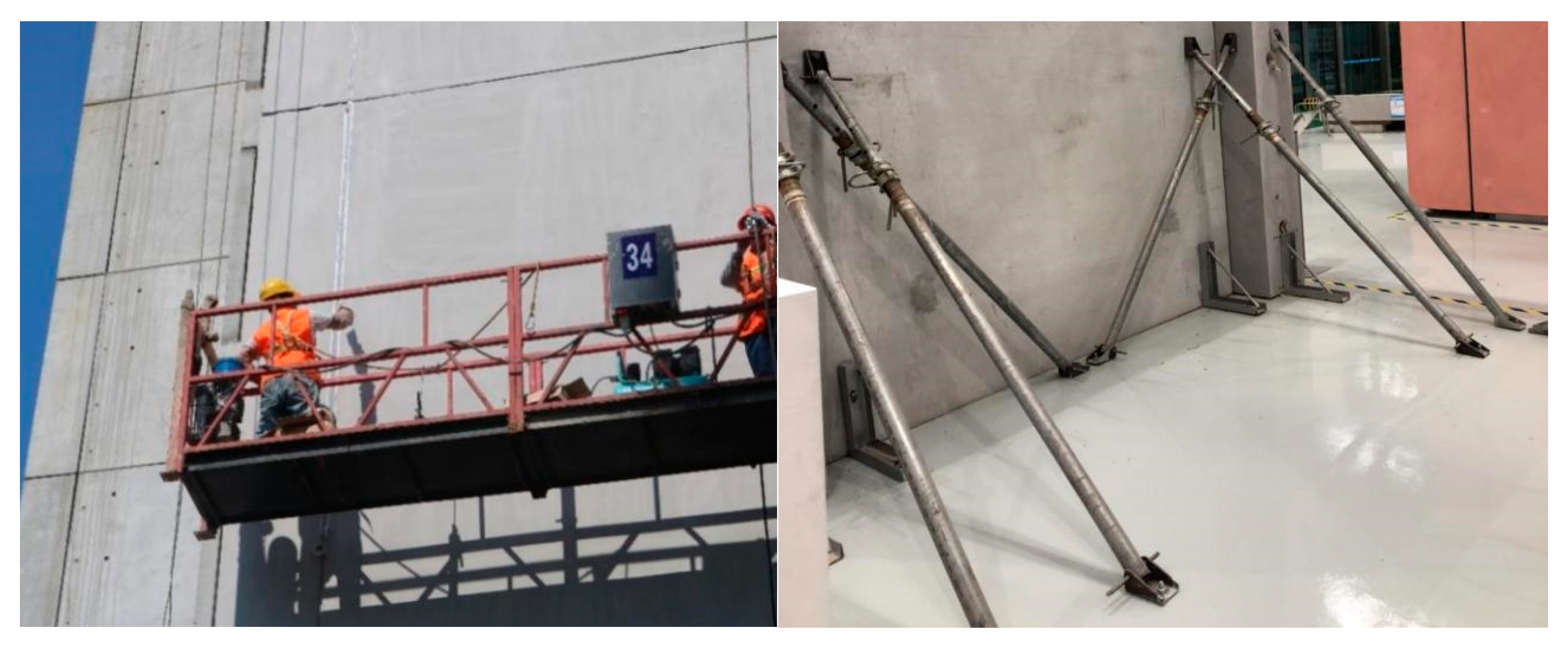
An off-site construction project in Wuhan, China was selected as the test bed to analyze and validate the proposed scheduling approach. The multistory project has a gross floor area of 18,590 m2 with 22 floors. The prefabricated building elements are used to accelerate construction (see Figure 5). To support on-site activities and on-time provision of prefabricated elements, a multi-supplier arrangement was adopted (multiple off-site manufacturers engaged).
The complexity of scheduling in prefabricated construction is partially caused by dependencies within and amongst three groups of on-site and off-site activities. In the case project, for example, the tight schedule (planned for 32 days) to complete manufacturing and installation of prefabricated elements on each floor required careful alignment of the three activity groups.
Off-site manufacturing of prefabricated elements is followed by on-site installation activities, such as crane lifting, joint grouting, and welding. Both off-site and on-site activities are related to predecessors and successors, where delays cause ripple effects in the project network. Table 2 provides a list of on-site activities with durations and required resources in the case project.
The quantities and types of prefabricated components are shown in Table 3. Based on concrete volume, components are configured to two suppliers, A and B (Table 4). Supplier A is responsible for vertical components, while supplier B is in charge of producing superposed beams, superposed floor slabs, and heteromorphic components. The job of manufacturing each type of component is defined as an activity. It is assumed that storage does not consume labor, whereas the activity of transportation requires a workforce. Therefore, the activity of delivery (YS) is added in both spaces, as shown in Table 4, separately describing parameters of 10 sorts of practical activities in space A and 12 sorts of practical activities in space B.
In order to clarify the proportional relationship between resource and duration in each activity and simplify calculation, the parameters in this case study are all measured without units. The relevant parameters are set as follows: the cost of single workforce per day in installation space λ 0 = 100; the cost of single workforce per day in the two production spaces λ 1 = 80, λ 2 = 85; ration factor of TW μ = 0.1; cost of TW management per day w = 50; the parameter of storage cost per day caused by pre-arrival α = 3; the parameter of penalty cost per day caused by post-arrival β = 8; weight parameters in the static final objective function η 1 = 0.6 , η 2 = 0.4 ; the planned overall duration of the project D = 32.

6.1. Calculation of Static Model

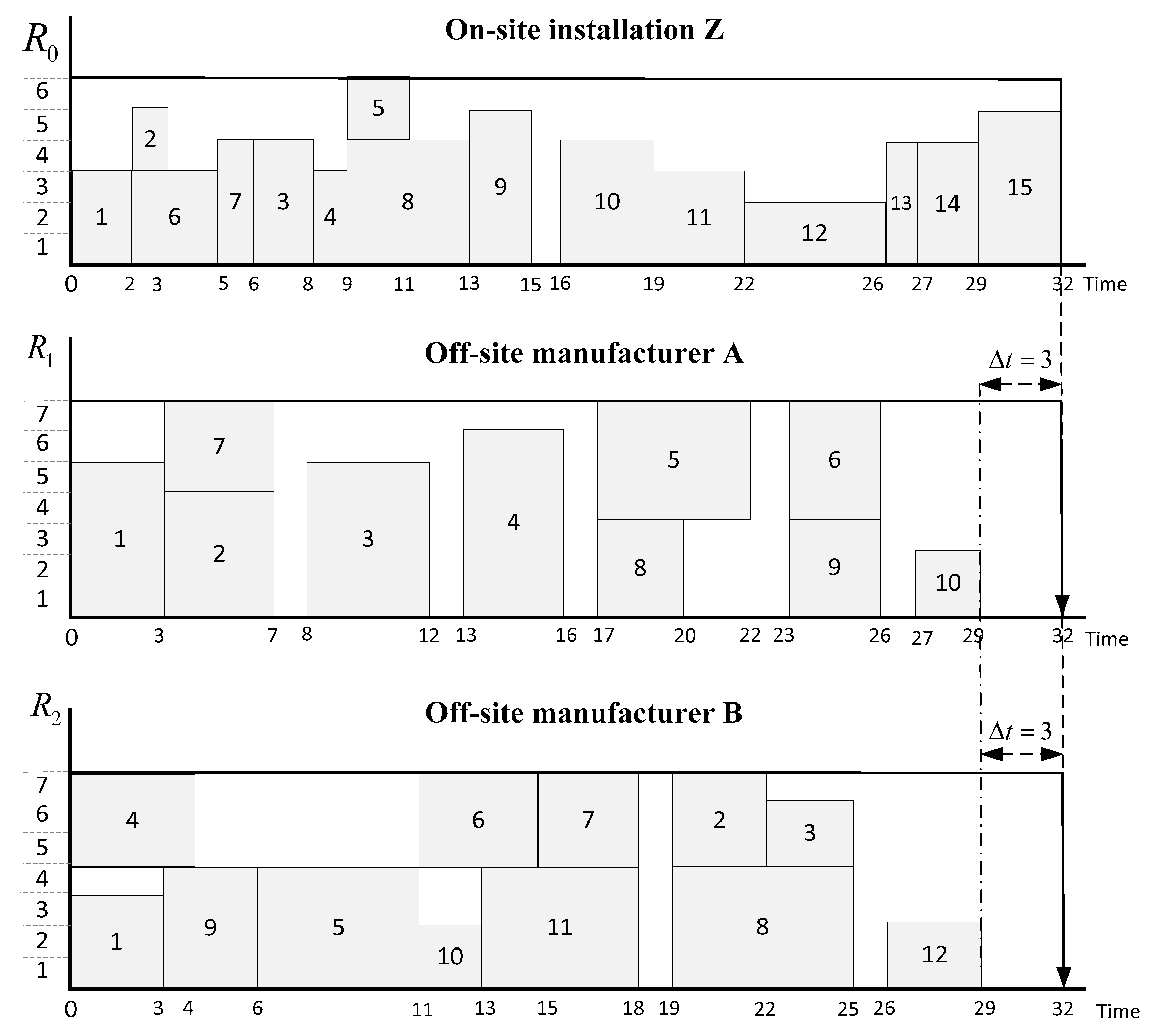
Referring to the mathematical function in the static scheduling model, SA is adopted to obtain the initial optimal scheduling plan of the assembly space S H 0 , which is presented in Table 5. With the constraint of the installation space’s duration and time window, the heuristic-based simulated annealing algorithm was used to attain scheduling plans of the two production spaces related with the latest ( S H i l ) and earliest ( S H i e ) supply times. To ensure the greatest efficiency of resource utilization, it is not required that the two production spaces must start at the same time with the assembly space. The minimum duration of the two manufacture spaces is calculated, that is, D 1 min = 24 and D 2 min = 27. In Table 5, the total float (TF) is defined as the flexible duration of the calculated schedules compared with the planned overall duration (32), which, in the assembly space, can be set as the limited value of delay corrected by one assembly operation ( ε = 1). In order to clearly describe the containment relationship among the scheduling plans, Figure 6 draws the initial static scheduling plans of three spaces related with the latest supply time ( S H i l ).

6.2. Calculation of Dynamic Model

Stage 1: Co-scheduling based on time buffering
Based on the above analysis, the time buffer ( b i j ) of each operation is presented as follows:
  • On-site installation Z
S H 0 = { 0 , 0 , 2 , 6 , 8 , 9 , 2 , 5 , 9 , 13 , 16 , 19 , 22 , 26 , 27 , 29 , 32 }
b 0 = { 0 , 0 , 3 , 0 , 0 , 2 , 0 , 0 , 0 , 1 , 0 , 0 , 0 , 0 , 0 , 0 , 0 }
  • Off-site manufacturer A
S H 1 = { 0 , 0 , 3 , 8 , 13 , 17 , 23 , 3 , 17 , 23 , 27 , 29 }
b 1 = { 0 , 0 , 1 , 1 , 1 , 1 , 1 , 1 , 3 , 1 , 0 , 3 }
  • Off-site manufacturer B
S H 2 = { 0 , 0 , 19 , 22 , 0 , 6 , 11 , 15 , 19 , 3 , 11 , 13 , 26 , 29 }
b 2 = { 0 , 0 , 0 , 1 , 2 , 0 , 0 , 1 , 1 , 0 , 0 , 1 , 0 , 3 }
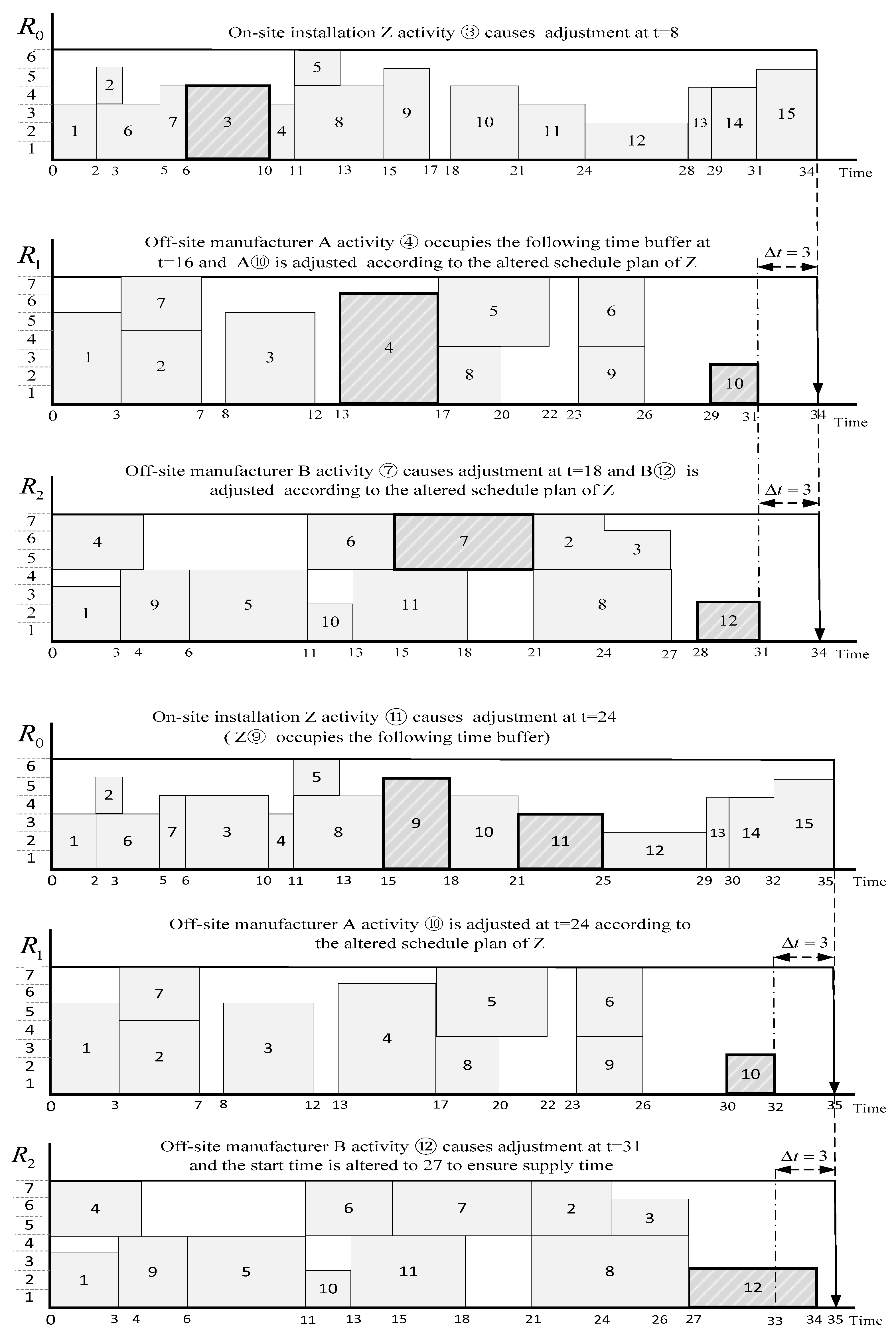
Adjusted by time buffer, the scheduling plans are presented in Figure 7. With the restriction of the deadline of project duration, in zone Z, there are three activities that are allocated time buffers, of which b 02 and b 05 are free floats due to the precedence relation, and b 09 is configured by the total float due to its greatest factor D B ( 9 ) . In the two production zones, the time buffer configuration is engaged due to the descending order of calculated D B ( j ) . In space A, b 18 is set as a free float, while others are allocated by the total float according to D B ( j ) . The same situation exists in zone B, where b 24 is set as a free float.
Stage 2: Dynamic adjustment
It is assumed that delays can be caused by six kinds of risk events in various activities, which have been assessed by advanced technology. It is known that the following risks would cause delays:
  • On-site installation Z
Z③ Prefabricated wall hoisting is delayed by 2; Z⑨ Prefabricated superposed beam lifting is delayed by 1; Z⑪ Prefabricated heteromorphic component lifting is delayed by 1.
  • Off-site manufacturer A
A④ Producing YWQ4 is delayed by 1.
  • Off-site manufacturer B
B⑦ Producing YDB4 is delayed by 3; B⑫ YS is delayed by 4.
Figure 8 shows that delays caused by Z⑨ and A④ can be eliminated by a time buffer. Therefore, the impacts of the two risks are out of consideration. Disrupted Z③ leads to the postponement by two units and modification measures at t = 8, based on which the influenced Z⑪ caused dynamic adjustment at t = 24. Thus, the duration of the installation operation is delayed by three units in total. Interference occurring in B⑦ postpones by a period of three units from t = 18. Since two units of delay can be curtailed by the time buffer, the starting time of B⑫ is adjusted at t = 27. Alteration at t = 31 is processed due to the remaining four units of delay induced by breaking. The changes are showed in Figure 8, which indicates that the altered supply times are during time windows without effects on the following cycle.
The duration of the current cycle is delayed by three units due to the postponement of the installation operation, which requires elimination in the subsequent cycles. Since ε = 1 (the limited value of delay corrected by one assembly operation), rescheduling of the following three cycles is proposed to eliminate the delay.
The cost of rescheduling in assembly space is calculated by Equation (26):
Q 0 = C y = 2 4 ( j = 0 J ϕ 0 j | s 0 j s o j | ) ,
through which it is obtained that Q 0 = 975 . In a similar way, the costs of rescheduling in the two production spaces are calculated based on Equation (21), and the results are: Q 1 = 228 , Q 2 = 408 . The overall cost of rescheduling in the three working spaces is: Q = Q 0 + Q 1 + Q 2 = 1611 . The result shows that the program of cooperative rescheduling spends 1611 in total.

6.3. Comparing with the Common Program

The common method of coping with delay in construction projects is to improve the input of resources. Another program increasing the amount of workforce is proposed. The costs of the two programs will be compared to verify the efficiency of the collaborative scheduling program. By increasing workforce in space Z during Cy2, the operation of Z 2 would be fulfilled with the duration of 29. The cost of rescheduling can be calculated according to Equation (27):
P 0 = [ max ( t = s o j c o j 1 r o j ) R 0 ] λ 0 * D C y 2 ,
wherein D C y 2 is the duration of Z 2 , that is, 29, when the workforce is allocated as 7, which indicates max ( t = s o j c o j 1 r o j ) = 7 . The calculated result is: P 0 = 2900 . The altered schedule is presented in Figure 9.
It is required to reschedule the plans of manufacturing operations with the restricted period of 29, the cost of which to be gained is: Q 1 = 60 , Q 2 = 204 . The total cost of rescheduling in the three working spaces in this program is: Q = P 0 + Q 1 + Q 2 = 3164 .
Comparing the two programs, the first program’s cost is less than the second program’s cost, which indicates that the dynamic co-scheduling model is more efficient and economical in the aspect of managing delay caused by disruptions.

6.4. Discussion

The application in the case project validates that the established scheduling models are efficient in solving risk delays while minimizing cost. This can be provided as an effective approach for collaborative scheduling in off-site construction. The contributions of this research are listed as follows:
  • This study utilizes SA in work flow scheduling to obtain the optimized schedule plan referring to combinatorial targets for off-site construction.
  • The established models firstly consider multiple suppliers related to one assembly site.
  • The methodology analyzed in this study can effectively improve the schedule’s robustness in risky environments to support the sustainable development of prefabrication.
  • However, the following limitations deserve to be further studied:
  • The actual construction environment is more complicated, with, for instance, various risk events disrupting one activity or one risk event disrupting various activities, which is not under consideration in the case study.
  • The more complicated workflows or other limited constraints can increase the difficulty of calculation and extend the calculation time, which is also the inherent defect of SA.
  • This application is based on the assumption of exact assessment of risk events and related delay durations. Actually, the prediction of relevant parameters may not achieve the demanded accuracy using existing tools.

7. Conclusions

The absence of a systematic analysis in prefabricated construction to collaboratively schedule on-site and off-site operations was identified as a gap and provided the rationale for this research. In the absence of risk disruptions and considering the total project duration as the main constraint, the scheduling is orchestrated on the basis of optimal resource utilization solved by a heuristic-based simulated annealing algorithm within computer technology. However, delay risks should be addressed using collaborative scheduling of on-site and off-site project activities. After proposing a collaborative scheduling approach, a case project involving multiple off-site suppliers was used for validation and testing. This study contributes to the body of knowledge in prefabricated construction management by streamlining collaborative scheduling in prefabrication. The established models provide construction managers with decision support systems with the aims of minimizing delays and related cost overruns.
Future research can focus on prefabrication projects in which logistics and transportation of elements from factory to site are also considered as a potential source of risk delay. This remains a limitation for this paper, as the focus was placed on manufacturing and on-site activities with deterministic (single point estimate) durations and costs. Future research should consider a wider range of scenarios by adopting a stochastic approach.

Author Contributions

Conceptualization, W.C. and M.A.; methodology, W.C. and Y.Y.; software, Y.Y.; validation, K.C.; formal analysis, W.C.; investigation, Y.Z.; resources, W.C. and Y.Z.; data curation, Y.Z.; writing—original draft preparation, W.C.; writing—review and editing, W.C. and Y.Z.; visualization, Y.Z.; supervision, M.A.; project administration, W.C. All authors have read and agreed to the published version of the manuscript.

Funding

This research received no external funding.

Acknowledgments

The authors are grateful to the China State Construction Technology Wuhan Co., LTD and its managers for providing information and data for this research on the real project application.

Conflicts of Interest

No of conflicts of interest exist in the submission of this manuscript, and it is approved by all authors for publication.

Data Availability

All data, models, and code generated or used during the study appear in the submitted article.

References

  1. Boafo, F.E.; Kim, J.-H.; Kim, J.-T. Performance of Modular Prefabricated Architecture: Case Study-Based Review and Future Pathways. Sustainability 2016, 8, 558. [Google Scholar] [CrossRef] [Green Version]
  2. Arashpour, M.; Wakefield, R.; Blismas, N.; Maqsood, T. Autonomous production tracking for augmenting output in off-site construction. Autom. Constr. 2015, 53, 13–21. [Google Scholar] [CrossRef]
  3. Gong, P.; Teng, Y.; Li, X.; Luo, L. Modeling Constraints for the On-Site Assembly Process of Prefabrication Housing Production: A Social Network Analysis. Sustainability 2019, 11, 1387. [Google Scholar] [CrossRef] [Green Version]
  4. Jiang, W.; Luo, L.; Wu, Z.; Fei, J.; Antwi-Afari, M.F.; Yu, T. An Investigation of the Effectiveness of Prefabrication Incentive Policies in China. Sustainability 2019, 11, 5149. [Google Scholar] [CrossRef] [Green Version]
  5. Tomar, A.; Bansal, V.K. Scheduling of repetitive construction projects using geographic information systems: An integration of critical path method and line of balance. Asian J. Civ. Eng. 2019, 20, 549–562. [Google Scholar] [CrossRef]
  6. Hendradewa, A.P. Schedule Risk Analysis by Different Phases of Construction Project Using CPM-PERT and Monte-Carlo Simulation. In Proceedings of the 11th International Seminar on Industrial Engineering and Management: Technology and Innovation Challenges Towards Industry 4.0 Era, ISIEM, Makasar, South Sulawesi, Indonesia, 27–29 November 2018; Volume 528. [Google Scholar] [CrossRef] [Green Version]
  7. Wang, J.; Zeng, S.; Ju, J. Construction Schedule Management Using Resource-Constrained Project Scheduling Model. Tongji Daxue Xuebao 2017, 45, 1561–1568. (In Chinese) [Google Scholar]
  8. Lawrence, S.R.; Morton, T.E. Resource-constrained multi-project scheduling with tardy costs: Comparing myopic, bottleneck, and resource pricing heuristics. Eur. J. Oper. Res. 1993, 64, 168–187. [Google Scholar] [CrossRef]
  9. Tsubakitani, S.; Deckro, R.F. A heuristic for multi-project scheduling with limited resources in the housing industry. Eur. J. Oper. Res. 1990, 49, 80–91. [Google Scholar] [CrossRef]
  10. Mohanty, R.P.; Siddiq, M.K. Multiple projects-multiple resources-constrained scheduling: Some studies. Int. J. Prod. Res. 1989, 27, 261–280. [Google Scholar] [CrossRef]
  11. Ko, C.-H.; Wang, S.-F. GA-based decision support systems for precast production planning. Autom. Constr. 2010, 19, 907–916. [Google Scholar] [CrossRef]
  12. Ko, C.-H.; Wang, S.-F. Precast production scheduling using multi-objective genetic algorithms. Expert Syst. Appl. 2011, 38, 8293–8302. [Google Scholar] [CrossRef]
  13. Yang, Z.; Ma, Z.; Wu, S. Optimized flowshop scheduling of multiple production lines for precast production. Autom. Constr. 2016, 72, 321–329. [Google Scholar] [CrossRef] [Green Version]
  14. Arashpour, M.; Kamat, V.; Bai, Y.; Wakefield, R.; Abbasi, B. Optimization modeling of multi-skilled resources in prefabrication: Theorizing cost analysis of process integration in off-site construction. Autom. Constr. 2018, 95, 1–9. [Google Scholar] [CrossRef]
  15. Arashpour, M.; Wakefield, R.; Abbasi, B.; Arashpour, M.; Hosseini, M.R. Optimal process integration architectures in off-site construction: Theorizing the use of multi-skilled resources. Arch. Eng. Des. Manag. 2017, 14, 46–59. [Google Scholar] [CrossRef]
  16. Li, C.Z.; Xu, X.; Shen, G.Q.; Fan, C.; Li, X.; Hong, J. A model for simulating schedule risks in prefabrication housing production: A case study of six-day cycle assembly activities in Hong Kong. J. Clean. Prod. 2018, 185, 366–381. [Google Scholar] [CrossRef]
  17. Wang, J.; Li, W. Study on Factors Affecting Construction Schedule of Prefabricated Buildings Based on PCA. In Proceedings of the International Conference on Construction and Real Estate Management, Guangzhou, China, 10–12 November 2017. [Google Scholar] [CrossRef]
  18. Ji, Y.; Qi, L.; Liu, Y.; Liu, X.; Li, H.X. Assessing and Prioritising Delay Factors of Prefabricated Concrete Building Projects in China. Appl. Sci. 2018, 8, 2324. [Google Scholar] [CrossRef] [Green Version]
  19. Li, C.Z.; Zhong, R.Y.; Xue, F.; Xu, G.; Chen, K.; Huang, G.G.; Shen, G.Q. Integrating RFID and BIM technologies for mitigating risks and improving schedule performance of prefabricated house construction. J. Clean. Prod. 2017, 165, 1048–1062. [Google Scholar] [CrossRef]
  20. Kaplinski, O. Planning instruments in construction management. Technol. Econ. Dev. Econ. 2008, 14, 449–451. [Google Scholar] [CrossRef]
  21. Hola, B.; Schabowicz, K. Estimation of earthworks execution time cost by means of artificial neural networks. Autom. Constr. 2010, 19, 570–579. [Google Scholar] [CrossRef]
  22. Yang, J.B.; Taroun, D.L.A. Construction Risk Modeling and Assessment: Insights from a Literature Review. Built Hum. Environ. Rev. 2011, 4, 87–97. [Google Scholar]
  23. Van De Vonder, S.; Demeulemeester, E.; Herroelen, W.; Leus, R. The use of buffers in project management: The trade-off between stability and makespan. Int. J. Prod. Econ. 2005, 97, 227–240. [Google Scholar] [CrossRef] [Green Version]
  24. Jaskowski, P. Methodology for enhancing reliability of predictive project schedules in construction. Eksploatacja Niezawodn. Maint. Reliab. 2015, 17, 470–479. [Google Scholar] [CrossRef]
  25. Mehta, S.V.; Uzsoy, R.M. Predictable scheduling of a job shop subject to breakdowns. IEEE Trans. Robot. Autom. 1998, 14, 365–378. [Google Scholar] [CrossRef]
  26. Herroelen, W.; Leus, R. The construction of stable project baseline schedules. Eur. J. Oper. Res. 2004, 156, 550–565. [Google Scholar] [CrossRef]
  27. Schatteman, D.; Herroelen, W.; Van De Vonder, S.; Boone, A. Methodology for Integrated Risk Management and Proactive Scheduling of Construction Projects. J. Constr. Eng. Manag. 2008, 134, 885–893. [Google Scholar] [CrossRef]
  28. Duque-Antón, M. Constructing efficient simulated annealing algorithms. Discret. Appl. Math. 1997, 80, 115. [Google Scholar] [CrossRef] [Green Version]
  29. Payá, I.; Yepes, V.; González-Vidosa, F.; Hospitaler, A. Multiobjective Optimization of Concrete Frames by Simulated Annealing. Comput. Civ. Infrastruct. Eng. 2008, 23, 596–610. [Google Scholar] [CrossRef]
  30. Yeh, I.-C. Construction-Site Layout Using Annealed Neural Network. J. Comput. Civ. Eng. 1995, 9, 201–208. [Google Scholar] [CrossRef]
  31. Wu, K.; De Soto, B.G.; Zhang, F. Spatio-temporal planning for tower cranes in construction projects with simulated annealing. Autom. Constr. 2020, 111, 103060. [Google Scholar] [CrossRef]
  32. Ryu, D.-W.; Kim, J.I.; Suh, S.; Suh, W. Evaluating risks using simulated annealing and Building Information Modeling. Appl. Math. Model. 2015, 39, 5925–5935. [Google Scholar] [CrossRef]
  33. Leung, T.; Chan, C.K.; Troutt, M.D. Application of a mixed simulated annealing-genetic algorithm heuristic for the two-dimensional orthogonal packing problem. Eur. J. Oper. Res. 2003, 145, 530–542. [Google Scholar] [CrossRef]
  34. Suliman, M.O.; Kumar, V.S.; Abdulal, W. Optimization of uncertain construction time-cost trade off problem using simulated annealing algorithm. In Proceedings of the 2011 World Congress on Information and Communication Technologies, Mumbai, India, 11–14 December 2011; pp. 489–494. [Google Scholar]
  35. Nasirian, A.; Arashpour, M.; Abbasi, B. Critical Literature Review of Labor Multiskilling in Construction. J. Constr. Eng. Manag. 2019, 145, 04018113. [Google Scholar] [CrossRef]
  36. Hosseini, M.R.; Martek, I.; Chileshe, N.; Zavadskas, E.K.; Arashpour, M. Assessing the Influence of Virtuality on the Effectiveness of Engineering Project Networks: “Big Five Theory” Perspective. J. Constr. Eng. Manag. 2018, 144, 04018059. [Google Scholar] [CrossRef]
  37. Hoel, K.; Taylor, S.G. Quantifying buffers for project schedules. Prod. Inventory Manag. J. 1999, 40, 43–47. [Google Scholar]
  38. He, Z.W.; Liu, R.J.; Yu, X.U. Robust scheduling optimization for resource-constrained project based on random duration of activities. Syst. Eng. Theory Pract. 2013, 33, 650–659. [Google Scholar]
  39. Lambrechts, O.; Demeulemeester, E.; Herroelen, W. A tabu search procedure for developing robust predictive project schedules. Int. J. Prod. Econ. 2008, 111, 493–508. [Google Scholar] [CrossRef]
Figure 1. Operation relationships in off-site construction.
Sustainability 12 09266 g001
Figure 2. Flowchart of this research methodology.
Sustainability 12 09266 g002
Figure 3. Solution steps of the static scheduling model.
Sustainability 12 09266 g003
Figure 4. Dynamic scheduling algorithm.
Sustainability 12 09266 g004
Figure 5. On-site installation and off-site manufacturing of prefabricated elements.
Sustainability 12 09266 g005
Figure 6. Static schedules in the case project.
Sustainability 12 09266 g006
Figure 7. Scheduling plans’ allocated time buffers.
Sustainability 12 09266 g007
Figure 8. Dynamic adjustment of scheduling plans related with disruptions.
Sustainability 12 09266 g008
Figure 9. Altered schedule based on increasing workforce.
Sustainability 12 09266 g009
Table 1. Modeling notations and symbols.
IndicesSpecification
iConstruction zones; i = 0 indicates on-site installation, i = 1, 2 indicates manufacturing
jWorking activities; j = 1 , 2 J , where J is the last activity in an operation
tTime; t = 0 , 1 , 2 T n T N , where T N is the total duration of the whole project
Δ t Duration of the time window (TW)
μ Ration factor of TW, μ > 0
wCost of TW management per day
T n a The earliest manufacturing time in cycle n (Cyn)
T n b The latest manufacturing time in Cyn
α The parameter of storage cost per day, α > 0
β The parameter of penalty cost per day, β > 0
k Resources; k = 1 , 2 K , where K is the total number of the renewable resource types
d i j The duration of activity j in construction zone i
s i j The starting date of activity j in construction zone i
c i j The finishing date of activity j in construction zone i, c i j = s i j + d i j
Y i h The set of preceding activities of j in construction zone i
V i f The set of succeeding activities of j in construction zone i
A i t The set of activities in progress on day t in construction zone i
N i All the activities included in construction zone i
R i k The available quantity of resource k in construction zone i
R k
r i j k
Maximum availability of resource k, where R i k R k
The quantity of resource k required by activity j in construction zone i
λ i k Cost of single unit k per day in construction zone i
P i Total cost in construction zone i
D i Duration of the operation in zone i
DTotal duration of the whole project
Table 2. On-site activities in the case project.
ActivityName Duration   d 0 j Labor   r 0 j Preceding Activity Penalty   Factor   φ 0 j
STStart00-0
1Component approach23ST3
2Measurement and setting out12ST3
3Prefabricated wall hoisting241, 29
4Installation of wall with oblique support 1334
5Plug joint, sleeve grouting, and cast-in-place walls and columns2244
6Rebar colligation and formwork3314
7Post-cast strip formwork 1464
8Rebar colligation and formwork of cast-in-place beams4475
9Prefabricated superposed beam lifting255, 88
10Prefabricated superposed slab lifting3496
11Prefabricated heteromorphic component lifting332, 107
12Colligation of rebar below slab in cast-in-place zone 42115
13Embedded pipeline installation14125
14Colligation of rebar above beam and slab 24136
15Structural concrete pouring35148
SFEnd0015200
Table 3. Types and quantities of prefabricated components required for a standard layer.
NumberComponentTypeQuantity Total   Volume   ( m 3 )
1YWQ64371.92
2YNQ31912.73
3YDL33134.72
4YDB5805.93
5YYB187.41
6YKB151.47
Table 4. Names and parameters of activities of the two suppliers.
Activity NumberActivity Name Duration   d 1 j Labor   r 1 j Preceding Activity Penalty   Factor φ 1 j
Off-site manufacturer ASTStart00-0
1YWQ135ST4
2YWQ24415
3YWQ34527
4YWQ43637
5YWQ55445
6YWQ63456
7YNQ143ST4
8YNQ23374
9YNQ33384
10YS225, 910
SFEnd00107
Off-site manufacturer BSTStart00-0
1YDL133ST4
2YDL23314
3YDL33224
4YDB143ST6
5YDB25447
6YDB34358
7YDB43368
8YDB56477
9YYB34ST5
10YKB2297
11YLT54108
12YS323, 8, 119
SFEnd00126
Table 5. Hybrid project activities: off-site manufacturing and on-site installation.
Activity Group Optimal   Resource R i Duration D i Cos ts   P i Scheduling   Plan   S H i Total Float
On-site installation Z R 0 = 6 D 0 = 31 P 0 = 755 S H 0 = { 0 , 0 , 5 , 6 , 8 , 11 , 2 , 5 , 9 , 13 , 15 , 18 , 21 , 25 , 26 , 28 , 31 } 1
Off-site manufacturer A R 1 = 7 D 1 l = 31 P 1 = 560 S H 1 l = { 0 , 7 , 10 , 14 , 18 , 21 , 26 , 10 , 23 , 26 , 29 , 31 } 8
D 1 e = 28 S H 1 e = { 0 , 4 , 7 , 11 , 15 , 18 , 23 , 7 , 20 , 23 , 26 , 28 } 5
Off-site manufacturer B R 2 = 7 D 2 l = 31 P 2 = 510 S H 2 l = { 0 , 4 , 22 , 25 , 6 , 10 , 15 , 19 , 22 , 7 , 15 , 17 , 28 , 31 } 5
D 2 e = 28 S H 2 e = { 0 , 1 , 1 , 23 , 3 , 7 , 12 , 16 , 19 , 4 , 12 , 14 , 25 , 28 } 2
Publisher’s Note: MDPI stays neutral with regard to jurisdictional claims in published maps and institutional affiliations.