Abstract
This paper is aimed at investigating the self-sensing properties of Portland-free alkali-activated binders doped with carbon-based nanofillers. Four different inclusions (carbon nanotubes, carbon nanofibers, carbon black and graphene nanoplatelets) were added into the matrix in the same amount. The physical and electromechanical properties were analyzed. The self-sensing capabilities of the samples were tested by applying a square wave voltage signal and measuring the variation of electrical resistance during cyclical compression tests. The results showed that the presence of nano-inclusions enhanced the sensing behavior of the materials, especially regarding the linearity and the hysteresis performances. Such results appear promising for the application of such novel and innovative nano-modified composites in the field of monitoring structures and infrastructures.
1. Introduction
Concrete is the most widely used construction material in the world, and its consumption is estimated at more than 25 billion tons [1]. Due to this huge production, the cement industry is characterized by a very strong environmental impact in terms of CO2 emissions, energy use and natural resource consumption. In particular, Portland cement (OPC) production requires a remarkable amount of energy (a modern cement plant requires from 2900 MJ to 3300 MJ for each ton of clinker produced) [2,3] and natural raw materials (on average, 1.22 tons of limestone and 0.31 tons of clay for each ton of clinker) [4], also contributing to global warming through an estimated 5–7% of CO2 emissions [5,6].
The use of alternative binders to Portland cement seems to be a promising strategy to improve the sustainability of concrete and develop eco-friendly construction materials [7,8,9,10]. Between these, alkali-activated slag (AAS) cements, produced by mixing ground granulated blast furnace slag (GGBFS) with alkaline activators, are widely investigated because they are able to combine outstanding binding capabilities and high durability [11,12,13,14,15] with an extremely low environmental impact in comparison to Portland cement [16]. In particular, it has been shown that AAS is characterized, at equal strength class, by reduced CO2 emissions (GWP, Global Warming Potential) and energy requirements (GER, Gross Energy Requirement) vs. OPC-based mixtures, with a decrease generally close to 80–90% and 70–80%, respectively [10]. Additionally, the NRMC (Natural Raw Materials Consumption) of alkali-activated slag-based mortars is about 30–40% lower in comparison with mixtures manufactured with traditional binders. This reduction in environmental impact is mainly due to the absence of the high temperature calcination step, whereas the calcination of Portland clinker not only consumes a large amount of fossil fuel-derived energy, but also releases CO2 as a reaction product. Although the use of an alkaline hydroxide or silicate activating solution rather than water for cement hydration reintroduces some greenhouse gas (GHG) cost, the overall CO2 saving due to widespread AAS utilization is expected to be highly significant [17]. Moreover, the re-use of GGBFS, an industrial by-product derived from steel manufacturing, limits the consumption of limestone and clay employed as raw materials for OPC production.
In the last few years, AAS has received growing attention from industries and researchers as a promising candidate in different civil engineering applications, such as the restoration of existing structures [18,19], refractory systems [20,21,22], fire-retardant plasters [23] and concrete sewer pipes [24]. On the other hand, new smart cementitious materials can help the development of buildings and infrastructures with integrated sensing and health-monitoring capabilities, thus increasing both the structural safety and service life of reinforced concrete structures [25].
Several studies have evaluated the self-sensing abilities of Portland cement-based concretes and mortars containing conductive fillers such as carbon nanotubes, carbon nanofibers, graphite powders and steel microfibers [26,27,28,29]. Research, including previous work by the authors, has demonstrated the monitoring capabilities of cement-based materials doped with conductive fillers and their promising application in structural health-monitoring [25,30,31,32,33,34,35], where issues related to the fillers’ dispersion and to the electrical setup represented the main bottlenecks to solve [36,37]. Of the notable literature about smart cementitious materials, only a few studies focus on the use of conductive fillers on geopolymers [38,39] or alkali-activated slag cement-based mixtures [40,41,42,43]. Recently, Rovnanik et al. [41] showed that AAS mortars are characterized by enhanced electrical conductivity properties compared to OPC-based mixtures due to the presence of mobile hydrated alkali ions and metallic microparticles. The reduced electrical resistivity of alkali-activated slag cement-based materials allows us to observe just enough piezoresistivity and consequent self-sensing properties, even without the addition of conductive materials. In order to improve the electrical conductivity of AAS, Vilaplana et al. [43] used carbon fibers at different dosages, highlighting gage factors (GF) for compressive cycles equal to 52 and 661 for the 0.29 and 0.58 vol.%, respectively. Rovnanik et al. [42] studied the effect of graphite addition (from 1 to 30 wt.% respect to GGBFS) on the mechanical properties and self-sensing capability of AAS mortars, identifying an optimum filler content to maximize the smart properties equal to 10 wt.%. However, the addition of an excessive amount of conductive fillers requires higher water dosages to ensure an adequate workability, strongly reducing the compressive strength of mortars.
The purpose of this work is the evaluation of the self-sensing capability of one-part alkali-activated slag cement-based mortars doped with different carbon-based nanofillers (carbon nanotubes, carbon nanofibers, carbon black and graphene nanoplatelets). Physical, mechanical and electromechanical tests have been carried out. The results show that all nano-modified materials exhibited enhanced properties, with the best sensitivity demonstrated by carbon black and carbon nanotubes.
2. Materials and Methods
The tested samples were beams with the dimensions 40 × 40 × 160 mm3. The matrix material was the same, while the added fillers, all carbon-based, had different dimensional, physical and chemical characteristics, and were added in the amount of 1% by weight with respect to the slurry. This percentage derives from a previous investigation conducted by the authors on cementitious composites doped with carbon inclusions. The same percentage of addition has been adopted for all the carbon fillers, in order to obtain comparable nano-modified composites. In particular, carbon nanotubes (CNT), carbon nanofibers (NF), carbon black (CB) and graphite nanoplatelets (GNP) have been investigated due to their good electrical capabilities.
2.1. Materials
2.1.1. Matrix
In this research, a ground granulated blast furnace slag (GGBFS, provided by Ecocem Ltd., Dublin, Ireland) was used as a precursor to manufacture one-part alkali-activated slag-based mortars. The density of the slag and specific surface was 3.13 g/cm3 and 345 m2/kg, respectively, while the average size of GGBFS particles was 12.42 μm (Mastersizer 3000, Malven Instruments Ltd., Cambridge, UK). The chemical composition (Inspect, FEI company Ltd., Hillsboro, OR, USA) of slag reported in Table 1 allowed us to calculate the Kb (basicity coefficient) and the Kq (quality coefficient) as reported by Wang et al. [44]:

Table 1.
Chemical composition of ground granulated blast furnace slag.
The XRD pattern (Rigaku Miniflex 60, Japan, X-ray source Cu Kα 0.15418 nm, 40 kV 15 mA, theta step 0.02, rate 1 °/min) showed the typical amorphous hump at 2θ = 25–35° of GGBFS (Figure 1) related to the short-range order of CaO-Al2O3-MgO-SiO2 glass structure according to Wang and Scrivener [45].
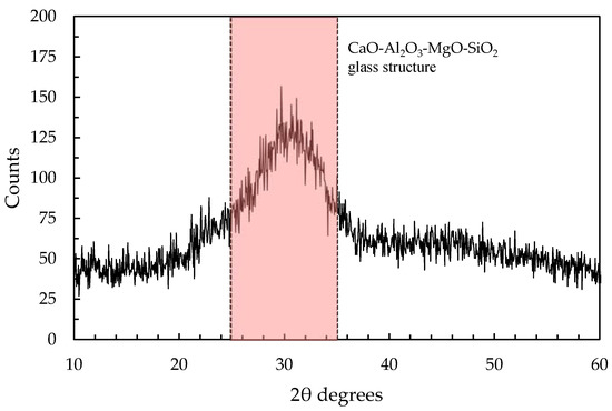
Figure 1.
XRD pattern of ground granulated blast furnace slag.
The solid alkaline activator was a blend of sodium silicate, potassium hydroxide and sodium carbonate (provided by Carlo Erba Spa, Italy, industrial grade) with a relative mass ratio equal to 7:3:1, as already used in previous studies by Coppola et al. [10,19]. As aggregates, five different natural siliceous sands (Table 2, provided by Sataf Srl, Italy) with a maximum diameter of 2.5 mm were combined according to the ASTM C33 limits. Finally, 20 °C deionized water was used to manufacture mortars.
Table 2.
Properties of aggregates.
2.1.2. Fillers
The fillers chosen for the composites were all carbon-based, but with different structures and aspect ratios. The carbon nanotubes (CNT) were Multi Walled, type Graphistrength C100, from Arkema (Germany) [46]. They are 1-dimensional multiple concentric cylinders with an average external diameter of 10 nm and length up to 10 µm. They possess a specific surface of the order of 200 m2/g and low apparent density, of the order of 100 kg/m3. The carbon nanofibers used in this research were type Pyrograf-III Carbon Nanofiber PE-19-XT-LHT (USA), considered 1-dimensional even if consisting of stacked cup linear structures. Their dimensions are greater than those of CNTs, with average diameters of 100 nm and lengths up to 200 µm. The Carbon black fillers adopted in this study were type Printex XE-2B produced by Orion (Luxemburg). They are 0-dimensional, as colloidal spherical particles of carbon. They were cheaper than the two previous fillers, and of the same typology of printer’s powder. The fourth carbon-based fillers were graphene nanoplatelets (GNP), produced by Cheap Tubes Inc. (USA), consisting of stacks of graphene layers of a final thickness up to 10 nm. They were 2-dimensional, with a visual appearance of grey powder, different from the other fillers which looked black. Table 3 summarizes the main characteristics declared by the producers of the four carbon-based fillers.
Table 3.
Carbon fillers’ characteristics (data provided by suppliers).
2.2. Mix Design
Five different one-part alkali-activated slag-based mortars were produced by varying the carbon filler type. The alkali content (Ac) and the silica modulus (Ms), calculated through Equations (3) and (4), were fixed at 0.0076 and 0.48, respectively, by using an activator to GGBFS ratio equal to 0.16.
The carbon fillers used for manufacturing the AAS composites, as explained before, are at the amount of 1% by slag mass. Furthermore, the water to slag ratio was set at 0.65, while the sand to slag ratio was 3. The composition of mortars is reported in Table 4.
Table 4.
Composition of mortars.
2.3. Sample Preparation
The reference AAS mortar (NEAT) was manufactured in accordance with the “Dry mixing method” proposed by Bayuaji et al. [47]. In particular, the procedure is composed of five steps:
- (i)
- Ground granulated blast furnace slag, alkali activator in powder or flakes and deionized water are placed into the steel bowl;
- (ii)
- The mixer starts at low speed (140 rpm for the revolving action, 62 rpm for the planetary action) for 30 s;
- (iii)
- The mixing proceeds at high speed (285 rpm for the revolving action, 125 rpm for the planetary action) for 60 s;
- (iv)
- The mixing stops for 90 s;
- (v)
- The mixer completes the procedure with a further 60 s at high speed.
In alkali-activated-based mortars containing carbon fillers, an aqueous solution containing deionized water and fillers was used instead of pure water (Figure 2a). In particular, the fillers were uniformly dispersed in the aqueous solution by means of a Branson 1510 (Branson Ultrasuoni Srl, Italy) sonicator for 15 min (Figure 2b). Then, the sonicated suspension was added to the mixtures and the mortars were prepared in accordance with the “Dry mixing method” (Figure 2c,d). Finally, the mortars were poured into 40 × 40 × 160 mm3 steel molds and protected from water evaporation with a plastic film (Figure 2e). After 24 h at 21 ± 1 °C, the specimens were demolded and cured in a climatic chamber at 21 ± 1 °C and R.H. 60 ± 5% until the mechanical tests.
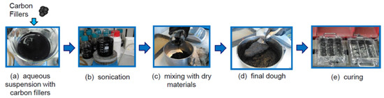
Figure 2.
Nano-modified sample’s preparation: addition (a) and dispersion (b) of nano-fillers, mixing of the components (c), mortar’s preparation (d), curing of the samples (e).
2.4. Experimental Setup
The workability of mortars was evaluated through a flow table according to EN 1015-3, and the specific mass at fresh state was measured in accordance with EN 1015-6. Moreover, the specific mass at hardened state, flexural and compressive strength were determined at 1, 7 and 28 days from casting (EN 1015-11). For the evaluation of the electrical properties of AAS-based composites, the samples were equipped with two external electrodes made of 5 mm long ribs in copper, and applied in the perimeter of each sample at a distance of 80 mm by the use of a conductive epoxy resin with 0.75% of graphite. The samples were tested after the resin polymerization. Figure 3 shows the sketch of the instrumented specimens. The electrical tests were carried out by applying a voltage to the samples with a model RIGOL DG1022 generator (Italy), and measuring the current signal by using a DAQ NI PXIe-1073 (USA) equipped with a digital multimeter, model NI PXI-4071. The copper strips were directly connected to the function generator and the acquisition system (Figure 3a). The electromechanical tests consisted of compressive cycles of loading/unloading in the range of 1–3 kN, carried out in the longitudinal direction by the use of a Controls press with a maximum load of 15 kN. Three LVDTs were placed at 120° in order to evaluate the displacement (Figure 3b).
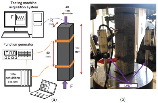
Figure 3.
Setup of electromechanical tests: (a) Sketch and (b) detail of sample and LVDTs.
The electrical and electromechanical tests were carried out by applying a square wave voltage signal with a duty cycle of 50% between the values of −10 V and +10V, with a frequency of 1 Hz, and recording the electrical current with a sampling frequency of 10 Hz. Then, the outputs were sampled at 1 Hz, taking the point placed at about 80% of the positive part of each period of the square voltage signal [37]. The electrical resistance was computed using Ohm’s law:
where V is the applied constant voltage in the positive part of the square wave, equal to +10 V, I is the current intensity, and t represents the instant of acquisition of the signal.
3. Results and Discussion
3.1. General Characterization of Mortars
The workability of mortars is in the range of 190–240 mm and it decreases when the carbon fillers are added to the mixture, as reported in Table 5. This is primarily due to the large surface area of nano-fillers, which demands a great amount of water to wet the surface, thereby reducing the free water content required for lubrication at a fixed water/binder ratio [48]. Moreover, mortars containing carbon fillers are characterized by a lower density, both at fresh and hardened states, in comparison to NEAT mortar. This circumstance is probably due to voids forming within the matrix due to air entrapment associated with the addition of the fillers. The samples with CNT were too inhomogeneous and defective for electromechanical testing, and therefore not reliable enough to be considered for further investigation.
Table 5.
General properties of mortars.
Mortar manufactured without carbon fillers (NEAT) shows a compressive strength of about 7 MPa after 24 h, and 15 MPa and 19 MPa at 7 and 28 days, respectively (Figure 4). The addition of carbon fillers decreases the compressive strength of mixtures both at early and late ages up to 25%. The strength loss can be mainly ascribed to the reduction in specific mass (Figure 5) due to excessive air entrapment which occurred during the mixing of carbon fillers.
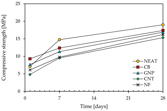
Figure 4.
Compressive strength development of mortars.
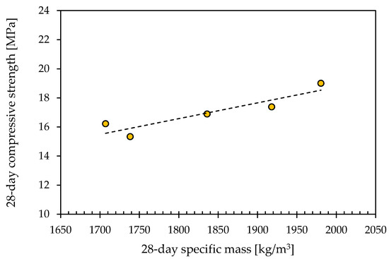
Figure 5.
The 28-day compressive strength of mortars vs. specific mass.
3.2. Electrical Tests
Electrical tests were conducted on unloaded samples. Each element was simply resting on the worktable, while the voltage was applied at the two electrodes and recorded for 600 s (Figure 6a). The electrical resistance has been obtained using Equation (5), considering the current intensity measured at the end of the tests. Figure 6b shows the results of the electrical tests. The samples with CB and NF appear slightly more conductive than the normal ones, while the samples with GNP exhibit a higher resistance, maybe due to the apparently higher porosity of the composite.
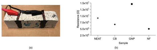
Figure 6.
Electrical tests: (a) sample during the tests; (b) electrical resistance of mortars.
3.3. Sensing Tests
Electromechanical tests were conducted by applying triangular cyclical loads, as reported in Figure 7. Each sample was instrumented as in Figure 7a. Figure 7b reports the stress variation on the samples during the tests. Electrical tension was applied at the copper electrodes, and the current was measured through the 2-probe method. Loads and electrical signals were recorded separately through two different data acquisition systems, with no perfect synchronization. The displacement was evaluated through the average value obtained from the LVDTs of the axial testing machine.
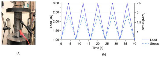
Figure 7.
Electromechanical tests: (a) an instrumented sample during the tests; (b) load and stress history.
Figure 8a shows the normalized variation of electrical resistance obtained from the electromechanical tests for the different composites. All the samples showed a certain sensitivity, even if the neat ones exhibited a slight drift of the signal. The sensitivity of the samples has been better analyzed through the computation of the gauge factor (GF), reported in Figure 9. The figure shows that the neat samples and the samples with CB and NF appeared more sensitive than the samples with GNP. However, the results of the neat samples were less repeatable and exhibited a greater variability.
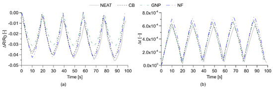
Figure 8.
Results of the electromechanical tests on normal and nano-modified samples: outputs of normalized variation of electrical resistance (a); strain variation (b).
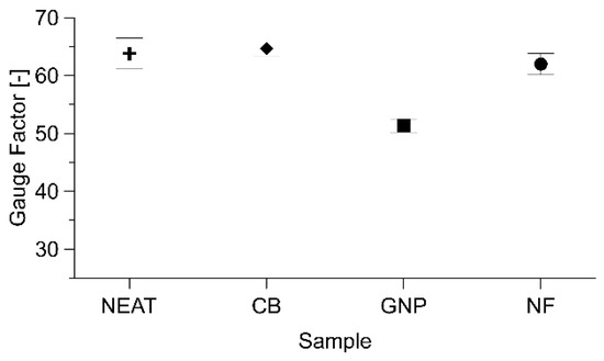
Figure 9.
Gauge factors obtained from electromechanical tests on all the samples.
Table 6 summarizes the results of the electromechanical tests, comparing the values of initial electrical resistance, GF and Sensitivity, defined as the product of the two previous features (Equation (6)):
where ΔR is the incremental variation in electrical resistance of the composites, R0 is the initial internal electrical resistance, GF is the gauge factor and is the axial strain, considered positive in compression. Table 6 confirms that the nano-materials with highest sensitivity are the composites with CB and NF. These last samples also appear to be the best performing ones in the analyses of the linearity of the signals, as reported in Figure 10 and Table 7. The results appear consistent with those obtained in previous research on cement composites with carbon-based fillers obtained with similar preparation procedures [31,33,49,50], even if some deviations are observed, which is due to the different setup and shape of the samples.
Table 6.
Initial resistance R0, Gauge Factor GF, Sensitivity S and linearity of the tested samples.
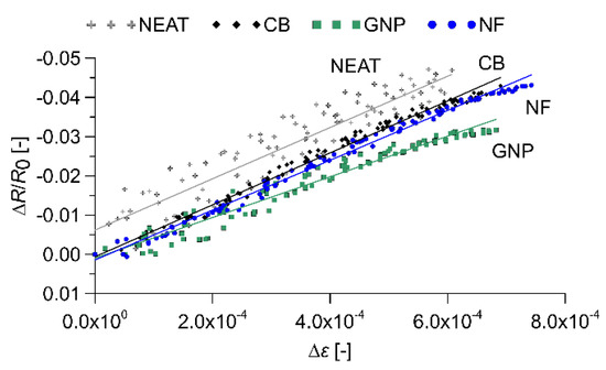
Figure 10.
Analysis of the linearity of the signals.
Table 7.
Evaluation of the linearity of the signal of all the samples.
Figure 11 shows, for all the sensors, the variation of fractional change in electrical resistance versus strain, for loading and unloading phases of the triangular cyclical loads. The results exhibit the enhanced performance of the nano-modified samples in comparison to the normal samples. The graphs also report the values of the hysteresis areas of all the samples: the numerical comparison indicates that the presence of nano carbon fillers in the composite determines the reduction in the non-linear behavior and in the hysteresis.
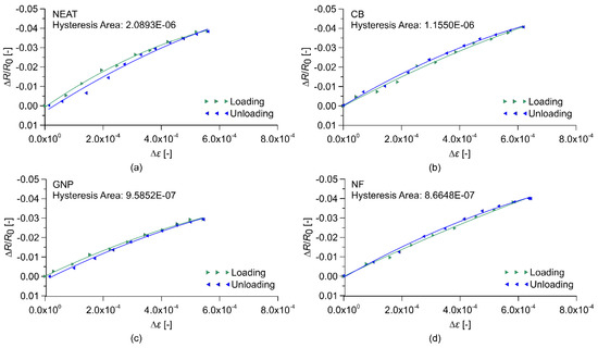
Figure 11.
Fractional change in electrical resistance vs. applied strain for loading and unloading phase under cyclic compression loads for samples: (a) NEAT, (b) with carbon black (CB), (c) with graphite nanoplatelets (GNP), (d) with carbon nanofibers (NF).
4. Conclusions
This paper has presented the investigation of the physical, mechanical and electromechanical properties of low environmental impact alkali-activated slag (AAS) cement-based mortars doped with different carbon-based nanofillers, i.e., nanotubes, nanofibers, carbon black and graphene nano-platelets. The development of these types of nano-modified materials is quite recent, but their possible applications appear promising. As a matter of fact, literature on doped AAS composites is still scarce, above all for smart conductive materials. The samples investigated in this research are produced by adding the same percentage of fillers, namely 1% of the weight of the slag. The mixes with carbon fillers exhibit acceptable workability, density and mechanical performances, albeit slightly lower than those characterizing the plain material. Electrical and electromechanical tests demonstrate the good performance of the nano-modified samples in sensing changes in stresses and strains. The composites with CB and CNF appear the most promising for applications in the monitoring of civil engineering structures and infrastructures.
Author Contributions
Conceptualization, A.D. and D.C.; methodology, A.D., D.C.; investigation, A.D., D.C., E.C.; data curation, A.M.; writing—original draft preparation, A.D., D.C.; writing—review and editing, L.C., F.U.; visualization, A.M., E.C.; supervision, L.C., F.U.; funding acquisition, F.U. All authors have read and agreed to the published version of the manuscript.
Funding
The research received no external funding
Conflicts of Interest
The authors declare no conflict of interest.
References
- Miller, S.A. Supplementary cementitious materials to mitigate greenhouse gas emissions from concrete: Can there be too much of a good thing? J. Clean. Prod. 2018, 178, 587–598. [Google Scholar] [CrossRef]
- Schneider, M.; Romer, M.; Tschudin, M.; Bolio, H. Sustainable cement production-present and future. Cem. Concr. Res. 2011, 41, 642–650. [Google Scholar] [CrossRef]
- Schneider, M. The cement industry on the way to a low-carbon future. Cem. Concr. Res. 2019. [Google Scholar] [CrossRef]
- Chen, C.; Habert, G.; Bouzidi, Y.; Jullien, A. Environmental impact of cement production: Detail of the different processes and cement plant variability evaluation. J. Clean. 2010. [Google Scholar] [CrossRef]
- Barcelo, L.; Kline, J.; Walenta, G.; Gartner, E. Cement and carbon emissions. Mater. Struct. 2014, 47, 1055–1065. [Google Scholar] [CrossRef]
- Habert, G.; Billard, C.; Rossi, P.; Chen, C.; Roussel, N. Cement production technology improvement compared to factor 4 objectives. Cem. Concr. Res. 2010, 40, 820–826. [Google Scholar] [CrossRef]
- Miller, S.A.; Myers, R.J. Environmental Impacts of Alternative Cement Binders. Environ. Sci. Technol. 2020, 54, 677–686. [Google Scholar] [CrossRef]
- Miller, S.A.; John, V.M.; Pacca, S.A.; Horvath, A. Carbon dioxide reduction potential in the global cement industry by 2050. Cem. Concr. Res. 2018, 114, 115–124. [Google Scholar] [CrossRef]
- Tataranni, P.; Besemer, G.M.; Bortolotti, V.; Sangiorgi, C. Preliminary Research on the Physical and Mechanical Properties of Alternative Lightweight Aggregates Produced by Alkali-Activation of Waste Powders. Materials (Basel Switz.) 2018, 11, 1255. [Google Scholar] [CrossRef]
- Coppola, L.; Coffetti, D.; Crotti, E. Pre-packed alkali activated cement-free mortars for repair of existing masonry buildings and concrete structures. Constr. Build. Mater. 2018. [Google Scholar] [CrossRef]
- Provis, J.L.; Palomo, A.; Shi, C. Advances in understanding alkali-activated materials. Cem. Concr. Res. 2015, 78, 110–125. [Google Scholar] [CrossRef]
- Thomas, R.J.; Peethamparan, S. Alkali-activated concrete: Engineering properties and stress–strain behavior. Constr. Build. Mater. 2015, 93, 49–56. [Google Scholar] [CrossRef]
- Coppola, L.; Coffetti, D.; Crotti, E.; Gazzaniga, G.; Pastore, T. The durability of one-part alkali activated slag-based mortars in different environments. Sustainability 2020, 12, 3561. [Google Scholar] [CrossRef]
- Jiang, H.; Qi, Z.; Yilmaz, E.; Han, J.; Qiu, J.; Dong, C. Effectiveness of alkali-activated slag as alternative binder on workability and early age compressive strength of cemented paste backfills. Constr. Build. Mater. 2019, 218, 689–700. [Google Scholar] [CrossRef]
- Coppola, L.; Coffetti, D.; Crotti, E.; Candamano, S.; Crea, F.; Gazzaniga, G.; Pastore, T. The combined use of admixtures for shrinkage reduction in one-part alkali activated slag-based mortars and pastes. Constr. Build. Mater. 2020, 248. [Google Scholar] [CrossRef]
- Habert, G.; D’Espinose De Lacaillerie, J.B.; Roussel, N. An environmental evaluation of geopolymer based concrete production: Reviewing current research trends. J. Clean. Prod. 2011, 19, 1229–1238. [Google Scholar] [CrossRef]
- Duxson, P.; Provis, J.L.; Lukey, G.C.; van Deventer, J.S.J. The role of inorganic polymer technology in the development of “green concrete”. Cem. Concr. Res. 2007, 37, 1590–1597. [Google Scholar] [CrossRef]
- He, J.; Bu, X.; Bai, W.; Zheng, W.; Gao, Q.; Wang, Y. Preparation and properties of self-compacting alkali-activated slag repair mortar. Constr. Build. Mater. 2020, 252, 119034. [Google Scholar] [CrossRef]
- Coppola, L.; Coffetti, D.; Crotti, E.; Marini, A.; Passoni, C.; Pastore, T. Lightweight cement-free alkali-activated slag plaster for the structural retrofit and energy upgrading of poor quality masonry walls. Cem. Concr. Compos. 2019, 104, 103341. [Google Scholar] [CrossRef]
- Manjunath, R.; Narasimhan, M.C.; Umesha, K.M. Studies on high performance alkali activated slag concrete mixes subjected to aggressive environments and sustained elevated temperatures. Constr. Build. Mater. 2019, 229, 116887. [Google Scholar] [CrossRef]
- Coppola, B.; Tardivat, C.; Richaud, S.; Tulliani, J.-M.; Montanaro, L.; Palmero, P. Alkali-activated refractory wastes exposed to high temperatures: Development and characterization. J. Eur. Ceram. Soc. 2020, 40, 3314–3326. [Google Scholar] [CrossRef]
- Horvat, B.; Ducman, V. Influence of particle size on compressive strength of alkali activated refractory materials. Materials (Basel) 2020, 13, 2227. [Google Scholar] [CrossRef] [PubMed]
- Virendra, K.; Amit, K.; Brajkishor, P. Influence of elevated temperature on alkali-activated ground granulated blast furnace slag concrete. J. Struct. Fire Eng. 2019, 12, 2040–2317. [Google Scholar]
- Khan, H.A.; Khan, M.S.H.; Castel, A.; Sunarho, J. Deterioration of alkali-activated mortars exposed to natural aggressive sewer environment. Constr. Build. Mater. 2018, 186, 577–597. [Google Scholar] [CrossRef]
- Han, B.; Ding, S.; Yu, X. Intrinsic self-sensing concrete and structures: A review. Measurement 2015, 59, 110–128. [Google Scholar] [CrossRef]
- Donnini, J.; Bellezze, T.; Corinaldesi, V. Mechanical, electrical and self-sensing properties of cementitious mortars containing short carbon fibers. J. Build. Eng. 2018, 20, 8–14. [Google Scholar] [CrossRef]
- Belli, A.; Mobili, A.; Bellezze, T.; Tittarelli, F. Commercial and recycled carbon/steel fibers for fiber-reinforced cement mortars with high electrical conductivity. Cem. Concr. Compos. 2020, 109, 103569. [Google Scholar] [CrossRef]
- Belli, A.; Mobili, A.; Bellezze, T.; Tittarelli, F.; Cachim, P. Evaluating the self-sensing ability of cement mortars manufactured with graphene nanoplatelets, virgin or recycled carbon fibers through piezoresistivity tests. Sustainability 2018, 10, 4013. [Google Scholar] [CrossRef]
- Kim, G.M.; Nam, I.W.; Yang, B.; Yoon, H.N.; Lee, H.K.; Park, S. Carbon nanotube (CNT) incorporated cementitious composites for functional construction materials: The state of the art. Compos. Struct. 2019, 227, 111244. [Google Scholar] [CrossRef]
- Camacho-Ballesta, C.; Zornoza, E.; Garcés, P. Performance of cement-based sensors with CNT for strain sensing. Adv. Cem. Res. 2016, 28, 274–284. [Google Scholar] [CrossRef]
- D’Alessandro, A.; Ubertini, F.; García-Macías, E.; Castro-Triguero, R.; Downey, A.; Laflamme, S.; Meoni, A.; Materazzi, A.L. Static and dynamic strain monitoring of reinforced concrete components through embedded carbon nanotube cement-based sensors. Shock Vib. 2017, 2017, 3648403. [Google Scholar] [CrossRef]
- Coppola, L.; Buoso, A.; Corazza, F. Electrical properties of carbon nanotubes cement composites for monitoring stress conditions in concrete structures. Appl. Mech. Mater. 2011, 82, 118–123. [Google Scholar] [CrossRef]
- Meoni, A.; D’alessandro, A.; Downey, A.; García-Macías, E.; Rallini, M.; Materazzi, A.L.; Torre, L.; Laflamme, S.; Castro-Triguero, R.; Ubertini, F. An experimental study on static and dynamic strain sensitivity of embeddable smart concrete sensors doped with carbon nanotubes for SHM of large structures. Sensors (Switzerland) 2018, 18, 831. [Google Scholar] [CrossRef] [PubMed]
- Park, H.M.; Park, S.M.; Lee, S.M.; Shon, I.J.; Jeon, H.; Yang, B.J. Automated generation of carbon nanotube morphology in cement composite via data-driven approaches. Compos. Part B Eng. 2019, 167, 51–62. [Google Scholar] [CrossRef]
- Kim, G.M.; Park, S.M.; Ryu, G.U.; Lee, H.K. Electrical characteristics of hierarchical conductive pathways in cementitious composites incorporating CNT and carbon fiber. Cem. Concr. Compos. 2017, 82, 165–175. [Google Scholar] [CrossRef]
- Wen, S.; Chung, D.D.L. Damage monitoring of cement paste by electrical resistance measurement. Cem. Concr. Res. 2000, 30, 1979–1982. [Google Scholar] [CrossRef]
- Downey, A.; D’Alessandro, A.; Ubertini, F.; Laflamme, S.; Geiger, R. Biphasic DC measurement approach for enhanced measurement stability and multi-channel sampling of self-sensing multi-functional structural materials doped with carbon-based additives. Smart Mater. Struct. 2017, 26, 65008. [Google Scholar] [CrossRef]
- Candamano, S.; Sgambitterra, E.; Lamuta, C.; Pagnotta, L.; Chakraborty, S.; Crea, F. Graphene nanoplatelets in geopolymeric systems: A new dimension of nanocomposites. Mater. Lett. 2019, 236, 550–553. [Google Scholar] [CrossRef]
- MacKenzie, K.J.D.; Bolton, M.J. Electrical and mechanical properties of aluminosilicate inorganic polymer composites with carbon nanotubes. J. Mater. Sci. 2009, 44, 2851–2857. [Google Scholar] [CrossRef]
- Rovnaník, P.; Míková, M.; Kusá, K. Electrical properties of alkali-Activated slag composite with combined graphite/CNT filler. IOP Conf. Ser. Mater. Sci. Eng. 2017, 251. [Google Scholar] [CrossRef]
- Rovnaník, P.; Kusák, I.; Bayer, P.; Schmid, P.; Fiala, L. Comparison of electrical and self-sensing properties of Portland cement and alkali-activated slag mortars. Cem. Concr. Res. 2019, 118, 84–91. [Google Scholar] [CrossRef]
- Rovnaník, P.; Kusák, I.; Bayer, P.; Schmid, P.; Fiala, L. Electrical and self-sensing properties of alkali-activated slag composite with graphite filler. Materials (Basel) 2019, 12, 1616. [Google Scholar] [CrossRef] [PubMed]
- Vilaplana, J.L.; Baeza, F.J.; Galao, O.; Zornoza, E.; Garcés, P. Self-sensing properties of alkali activated blast furnace slag (BFS) composites reinforced with carbon fibers. Materials (Basel) 2013, 6, 4776–4786. [Google Scholar] [CrossRef] [PubMed]
- Wang, S.D.; Scrivener, K.L.; Pratt, P.L. Factors affecting the strength of alkali-activated slag. Cem. Concr. Res. 1994, 24, 1033–1043. [Google Scholar] [CrossRef]
- Wang, S.-D.; Scrivener, K.L. Hydration products of alkali activated slag cement. Cem. Concr. Res. 1995, 25, 561–571. [Google Scholar] [CrossRef]
- Page, M.M.; Laurent, P.; Havel, M.; Roger, C. Arkema graphistrength multi-walled carbon nanotubes. In Proceedings of the 2008 NSTI Nanotechnology Conference and Trade Show, Boston, MA, USA, 1–5 June 2008; pp. 47–50. [Google Scholar]
- Bayuaji, R.; Yasin, A.K.; Susanto, T.E.; Darmawan, M.S.; Darmawan, S. A review in geopolymer binder with dry mixing method (geopolymer cement). AIP Conf. Proc. 2017, 1887, 20042. [Google Scholar] [CrossRef]
- Chuah, S.; Pan, Z.; Sanjayan, J.G.; Wang, C.M.; Duan, W.H. Nano reinforced cement and concrete composites and new perspective from graphene oxide. Constr. Build. Mater. 2014, 73, 113–124. [Google Scholar] [CrossRef]
- D’Alessandro, A.; Ubertini, F.; Laflamme, S.; Rallini, M.; Materazzi, A.L.; Kenny, J.M. Strain Sensitivity of Carbon Nanotube Cement-based Composites for Structural Health Monitoring. In Proceedings of the SPIE—The International Society for Optical Engineering, Las Vegas, NV, USA, 21–24 March 2016; Volume 9803, p. 980319. [Google Scholar]
- D’Alessandro, A.; Meoni, A.; Ubertini, F.; Luigi Materazzi, A. Strain Measurement in a Reinforced Concrete Beam Using Embedded Smart Concrete Sensors, Lecture Notes in Civil Engineering. In Proceedings of the Conference on Italian Concrete Days, Lecco, Italy, 14–15 June 2018; pp. 289–300. [Google Scholar]


Publisher’s Note: MDPI stays neutral with regard to jurisdictional claims in published maps and institutional affiliations. |
© 2020 by the authors. Licensee MDPI, Basel, Switzerland. This article is an open access article distributed under the terms and conditions of the Creative Commons Attribution (CC BY) license (http://creativecommons.org/licenses/by/4.0/).